Embed Size (px)
Citation preview
all-flo.com
C038 - PLASTIC 3/8 INCH AIR OPERATED DOUBLE DIAPHRAGM PUMP
PUMP OPERATIONS & MAINTENANCE MANUAL

all-flo.com
TABLE OF CONTENTS
2
SECTION 1 WARNINGS, DANGERS AND CAUTIONS 3
SECTION 2 MODEL DESIGNATION MATRIX 4
SECTION 3 PRINCIPLES OF OPERATION 5
SECTION 4 DIMENSIONAL DRAWINGS 6
SECTION 5 PERFORMANCE CURVES
RUBBER, TPE AND PTFE DIAPHRAGMS 7
SECTION 6 INSTALLATION,
INSTALLATION 8-9
TROUBLESHOOTING 10
OPERATION 11
MAINTENANCE 11
SECTION 7 REPAIR AND ASSEMBLY
PUMP WET END REMOVAL 12-13
AIR VALVE REMOVAL 14-15
TORQUE SPECIFICATIONS 15
SECTION 8 EXPLODED VIEWS AND PARTS LISTS 16-17
SECTION 9 ELASTOMERS AND REPAIR KITS 18
SECTION 10 WARRANTY AND REGISTRATION 19
all-flo.com 3
READ THESE WARNINGS AND SAFETY PRECAUTIONS PRIOR TO INSTALLATION OR OPERATION. FAILURE TO COMPLY WITH THESE INSTRUCTIONS COULD RESULT IN PERSONAL INJURY AND OR PROPERTY DAMAGE. RETAIN THESE INSTRUCTIONS FOR FUTURE REFERENCE.
WARNING Pump, valves and all containers mustbe properly grounded prior to handling flammable fluids and/or whenever static electricity is a hazard.
WARNING Prior to servicing the pump, ensure thatthe air and fluid lines are closed and disconnected. While wearing personal protective equipment, flush, drain and process liquid from the pump in a safe manner.
WARNING The TX marking refers to the maximumsurface temperature depending not on the equipment itself, but mainly on operating conditions. In this case, the maximum surface temperature depends upon the temperature of the process fluids.
CAUTION The temperature of the process fluidand air input must be no more than 36°F (20C) less of the maximum temperature allowed for the appropriate non-metallic material. See the list of temperatures below for each material’s maximum recommended temperature:
Buna-N (Nitrile): 10°F to 180°F (-12C to 82C)
Geolast®: 10°F to 180°F (-12C to 82C)
EPDM: -40°F to 280°F (-40C to 138C)
Santoprene®: -40°F to 225°F (-40C to 107C)
Viton® (FKM): -40°F to 350°F (-40C to 177C)
PTFE: 40°F to 220°F (4C to 104C)
Polyethylene: 32°F to 158°F (0C to 70C)
Polypropylene: 32°F to 180°F (0C to 82C)
PVDF: 0°F to 250°F (-18C to 121C)
Nylon: 0°F to 200°F (-18C to 93C)
Temperature limits are solely based upon mechanical stress and certain chemicals will reduce the maximum operating temperature. The allowable temperature range for the process fluid is determined by the materials in contact with the fluid being pumped. Consult a chemical resistance guide for chemical compatibility and a more precise safe temperature limit. Always use minimum air pressure when pumping at elevated temperatures.
CAUTION Do not lubricate air supply.
CAUTIONS — READ FIRST!WARNING
CAUTION
= Hazards or unsafe practices which could result in severe personal injury, death or substantial property damage
= Hazards or unsafe practices which could result in minor personal injury, product or property damage.
CAUTION Do not connect a compressed air sourceto the exhaust port of the pump.
WARNING Use only with liquid process fluid.
WARNING Maintenance must not be performedwhen a hazardous atmosphere is present.
CAUTION Do not exceed 120 psig (8.3 bar)air-inlet pressure.
CAUTION Do not exceed 10 psig (0.7 bar)or 23 ft-H2O suction pressure.
CAUTION Ensure all wetted components arechemically compatible with the process fluid and the cleaning fluid.
CAUTION Ensure pump is thoroughly cleaned andflushed prior to installation into a process line.
CAUTION Always wear Personal ProtectiveEquipment (PPE) when operating pump.
CAUTION Close and disconnect allcompressed air and bleed all air from the pump prior to service. Remove all process fluid in a safe manner prior to service.
CAUTION Blow out all compressed airlines in order to remove any debris, prior to pump installation. Ensure that the muffler is properly installed prior to pump operation.
CAUTION Ensure air exhaust is piped toatmosphere prior to a submerged installation.
CAUTION Ensure all hardware is set tocorrect torque values prior to operation.
SECTION 1

all-flo.com
MODEL DESIGNATION MATRIX-CLAMPED PLASTIC
SECTION 2
4
PRODUCT SERIES
FLUID CONNECTION TYPE
LIQUID SECTION
DIAPHRAGMVALVE/BALLVALVE SEAT
O-RINGS
SPECIAL (OTHER)
SPECIAL (PORTING)
AIR SECTION
SPECIAL (HARDWARE,
MUFFLER)
C 0 3 8 - 1 2 3 - 4 5 6 7 - 8 9 10
FLUID CONNECTION TYPES = NPS (NPT/BSP)
AIR SECTIONQ = Polypropylene Intermediate-Mechanical Shift
LIQUID SECTIONK = PVDFP = PolypropyleneY = Conductive Nylon
DIAPHRAGMSG = Geolast®
S = Santoprene®
T = PTFE
VALVE/BALLG = Geolast®
S = Santoprene®
T = PTFE V = Viton®/FKM3 = Stainless Steel
VALVE SEATK = PVDFP = Polypropylene3 = Stainless Steel
O-RINGSE = EPDMN = Buna-NT = PTFEV = Viton®/FKM
PORTINGS = Default (Suction Right/ Discharge Right)T = Suction Right / Discharge LeftX = Suction Left / Discharge RightY = Suction Left / Discharge LeftK = Suction Bottom / Discharge Center FrontL = Suction Bottom / Discharge Center RearN = Suction Bottom / Discharge RightO = Suction Bottom / Discharge LeftP = Suction Right / Discharge Center FrontQ = Suction Right / Discharge Center RearU = Suction Left / Discharge Center FrontV = Suction Left / Discharge Center Rear
SPECIAL OPTION (HARDWARE, MUFFLER, LUG)7 = Stainless Steel Hardware, Standard Muffler8 = Stainless Steel Hardware, Premium MufflerB = PTFE Coated Stainless Steel Hardware,
Standard MufflerC = PTFE Coated Stainless Steel Hardware,
Premium MufflerF = Stainless Steel Hardware, Standard Muffler,
Grounding Lug InstalledG = Stainless Steel Hardware, Premium Muffler,
Grounding Lug InstalledH = PTFE Coated Stainless Steel Hardware,
Standard Muffler, Grounding Lug InstalledI = PTFE Coated Stainless Steel Hardware,
Premium Muffler, Grounding Lug InstalledNote: Equipment must be grounded to achieve
ATEX rating it is recommended to configure the pump with a grounding lug option for ATEX applications.
SPECIAL OPTION (OTHER)0 = Standard1 = Cycle Counter Valve2 = Solenoid Adaptor Valve 110/50 Volt AC, 120/60
Volt AC3 = Solenoid Adaptor Valve 110/50 Volt AC, 120/60
Volt AC Explosion Proof4 = Solenoid Adaptor Valve 220/50 Volt AC, 240/60
Volt AC, 12 Volt DC5 = Solenoid Adaptor Valve 220/50 Volt AC, 240/60
Volt AC, 12 Volt DC Explosion Proof6 = Solenoid Adaptor Valve 220/50 Volt AC, 240/60
Volt AC, 125 Volt DC7 = Solenoid Adaptor Valve 220/50 Volt AC, 240/60
Volt AC, 125 Volt DC Explosion Proof8 = Solenoid Adaptor Valve 24 Volt DC9 = Solenoid Adaptor Valve 24 Volt DC, Explosion
ProofA = Grease Free (No lubrication assembly)
SIZE
WET END REPAIR KIT Wet end kits are available and consist of diaphragms, (back-up diaphragms if required), balls, seats and seat O-Rings. See matrix below.
1
2
6
7
8
9
10
Bold indicates recommended options
DIAPHRAGMVALVE/BALLVALVE SEAT
O-RINGS
C W E - 0 3 8 - 4 5 6 7 - P
PRODUCT
SERIES
WET END
REPAIR KIT
PUMP SIZE
3
4
5
MATERIAL
all-flo.com
PRINCIPLES OF OPERATION
6
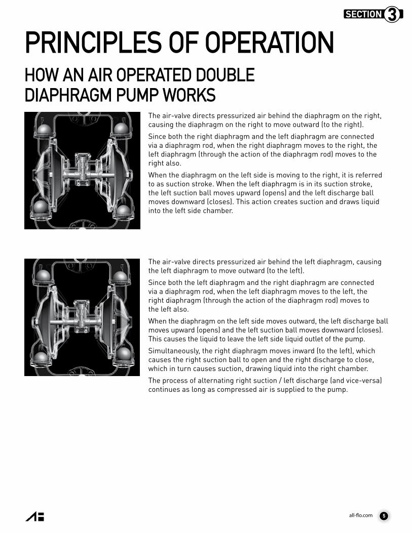
The air-valve directs pressurized air behind the diaphragm on the right, causing the diaphragm on the right to move outward (to the right).
Since both the right diaphragm and the left diaphragm are connected via a diaphragm rod, when the right diaphragm moves to the right, the left diaphragm (through the action of the diaphragm rod) moves to the right also.
When the diaphragm on the left side is moving to the right, it is referred to as suction stroke. When the left diaphragm is in its suction stroke, the left suction ball moves upward (opens) and the left discharge ball moves downward (closes). This action creates suction and draws liquid into the left side chamber.
The air-valve directs pressurized air behind the left diaphragm, causing the left diaphragm to move outward (to the left).
Since both the left diaphragm and the right diaphragm are connected via a diaphragm rod, when the left diaphragm moves to the left, the right diaphragm (through the action of the diaphragm rod) moves to the left also.
When the diaphragm on the left side moves outward, the left discharge ball moves upward (opens) and the left suction ball moves downward (closes). This causes the liquid to leave the left side liquid outlet of the pump.
Simultaneously, the right diaphragm moves inward (to the left), which causes the right suction ball to open and the right discharge to close, which in turn causes suction, drawing liquid into the right chamber.
The process of alternating right suction / left discharge (and vice-versa) continues as long as compressed air is supplied to the pump.
HOW AN AIR OPERATED DOUBLE DIAPHRAGM PUMP WORKS
5
SECTION 3

all-flo.com 7
3/8” PUMP DIMENSIONSCLAMPED PLASTIC
SECTION 4
6

all-flo.com
PERFORMANCE CURVESPERFORMANCE CURVE Performance Specifications
Max. Flow: 9 gpm (34.0 lpm)Max. Air Pressure: 120 psi (8.2 bar)Max. Solids: 1/16” (1.6 mm)Max. Suction Lift Dry: 10 ft-H2O (3.0 m-H2O)Max. Suction Lift Wet: 26 ft-H2O (7.9 m-H2O)Weight Polypropylene & Conductive Nylon: 3.8 lbs (1.7 kg)Weight PVDF: 5 lbs (2.3 kg)Air Inlet: 1/4” FNPTLiquid Inlet FNPT/FBSPT: 3/8”Liquid Outlet FNPT/FBSPT: 3/8”Height: 7.19” (182.6 mm)Width: 8.55” (217.2 mm)Depth: 4.82” (122.4 mm)
5SECTION
*Flow rates indicated on the chart(s) shown were determined by pumping water at flooded suction. For optimum life and performance, pumps should be specified so that daily operation parameters will fall in the center of the pump performance curve.
AIR CONSUMPTION (SCFM)
7

all-flo.com
SECTION 6
INSTALLATION, TROUBLESHOOTING AND MAINTENANCE INSTALLATIONPIPINGWhenever possible ensure the pump is installed using the shortest possible pipe lengths with the minimum amount of pipe fittings. Ensure all piping is supported independent of the pump.Suction and discharge piping should not be smaller than the connection size of the pump. When pumping liquids of high viscosity, larger piping may be used, in order to reduce frictional pipe loss.Employ flexible hoses in order to eliminate the vibration caused by the pump. Mounting feet can also be used to reduce vibration effects. All hoses should be reinforced, non-collapsible and be capable of high vacuum service. Ensure that all piping and hoses are chemically compatible with the process and cleaning fluid.For processes where pulsation effects should be reduced, employ a pulsation dampener on the discharge side of the pump. For self-priming applications, ensure all connections are airtight and the application is within the pumps dry-lift capability. Refer to product specifications for further details.For flooded suction applications, install a gate valve on the suction piping in order to facilitate service. For unattended flooded suction operation, it is recommended to pipe the exhaust air above the liquid source. In the event of a diaphragm failure this will reduce or eliminate the possibility of liquid discharging through the exhaust onto the ground.
LOCATIONEnsure that the pump is installed in an accessible location, in order to facilitate future service and maintenance.
AIREnsure that the air supply is sufficient for the volume of air required by the pump. Refer to product specifications for further details. For reliable operation, install a 5 micron air filter, air-valve and pressure regulator. Do not exceed the pumps maximum operating pressure of 120 psig.
REMOTE OPERATION Utilize a three way solenoid valve for remote operation. This ensures that air between the solenoid and the pump is allowed to “bleed off,” ensuring reliable operation. Liquid transfer volume is estimated by multiplying displacement per stroke times the number of strokes per minute
NOISECorrect installation of the muffler reduces sound levels. Refer to product specifications for further details.
SUBMERGED OPERATIONFor submersible operation, pipe the air exhaust to atmosphere
GROUNDING THE PUMPLoosen grounding screw and install a grounding wire. Tighten grounding screw. Wire size should be a 12 gauge wire or larger. Connect the other end of the wire to a true earth ground. Equipment must be grounded to achieve ATEX rating and it is recommended to configure the pump with a grounding lug option.
8

all-flo.com
SUGGESTED INSTALLATION
This illustration is a generic representation of an air operated double-diaphragm pump.
9

all-flo.com10
TROUBLESHOOTINGPROBLEM EFFECT/SOLUTION
Pump Will Not Cycle Discharge line closed or pluggedDischarge filter blockedCheck valve stuckAir filter blockedAir supply valve closedAir supply hooked up to muffler side of pumpCompressor not producing air or turned offMuffler iced or blindedDiaphragm rupturedPlant air supply line rupturedAir valve wear/debrisPilot sleeve wear/debrisDiaphragm rod brokenDiaphragm plate loose
Pumped Fluid Coming Out of Muffler Diaphragm rupturedDiaphragm plate looseInlet liquid pressure excessive (above 10 psig)
Pump Cycles but no Flow Inlet strainer cloggedSuction valve closedSuction line pluggedNo liquid in the suction tankSuction lift excessiveDebris stuck in valvesExcessive wear of check valvesAir leak on suction side with suction lift
Pump Cycles with Closed Discharge Valve Debris stuck in check valveExcessive wear of check valves
Pump Running Slowly/Not Steady Air compressor undersized Leak in air supplyAir-line, filter regulator or needle valve undersizedMuffler partially iced or blindedAir valve gasket leak or misalignmentAir valve wear/debrisPilot sleeve wear/debrisLiquid fluid filter blockedPump may be cavitating, reduce speed of operationSuction strainer clogged
Pump Will Not Prime Air leak in suction pipeAir leak in pump manifold connectionsSuction strainer and lines cloggedExcessive lift conditionsCheck valve wearDebris in check valve

all-flo.com
OPERATION The Air-Operated Double Diaphragm Pump requires a minimum of 20 psig of air to operate, with some variation according to diaphragm material. Increasing the air pressure results in a more rapid cycling of the pump and thus a higher liquid flow rate. In order to not exceed 120 psig of inlet air pressure, and for accurate control of the pump, it is suggested to use a pressure regulator on the air inlet. An alternate means of controlling the flow-rate of the pump is to use an inlet air valve and partially open or close accordingly. When the air valve is completely in the closed position, the pump will cease to operate. A third method of controlling the flow rate of the pump is to use a liquid discharge valve. Closing the liquid discharge valve will cause a decrease in the flow rate since the pump will operate against a higher discharge pressure.Solenoid control of the inlet air may also be used in order to facilitate remote operation. A three way solenoid valve is recommended, in order to allow the air to “bleed off” between the solenoid and the pump. Do not use valves for flow control on the suction side of the pump. (Closing or partially closing a liquid suction valve restrict the suction line and may cause damage to the diaphragms.) Suction strainers may be employed to reduce or eliminate larger solids, but routine maintenance is necessary in order to prevent a restriction on the suction.
MAINTENANCEDue to the unique nature of each application, periodic inspection of the pump is the best method to determine a proper maintenance schedule. A record should be kept of all repairs made to an installed pump. This will serve as the best predictor of future maintenance.Typical maintenance involves replacing of “wear-parts” such as the diaphragms, balls, valve seats and O-rings. Proper maintenance can ensure trouble-freeoperation of the pump. Refer to repair and assemblyinstructions for further details.
WARNING Maintenance must not be performed when a hazardous atmosphere is present.
MAINTENANCE SCHEDULE WEEKLY (OR DAILY) Make a visual check of the pump. If pumped fluid is leaking out of the pump, pipe fittings or muffler turn off pump and schedule maintenance.
EVERY THREE MONTHSInspect fasteners and tighten any loose fasteners to recommended torque settings.Schedule pump service based on pump’s service history.
11

all-flo.com
SECTION 7
12
REPAIR AND ASSEMBLYPUMP WET END REMOVAL
WARNING Prior to servicing the pump, ensure that the air and fluid lines are closed and disconnected. While wearing personal protective equipment, flush, drain and process liquid from the pump in a safe manner.
WARNING Maintenance must not be performed when a hazardous atmosphere is present.
TOOLS NEEDED1) Two Wrenches, 7/16 Inch
2) One Wrench, ½ Inch
3) Two Wrenches, ¾ Inch
4) One Screwdriver, Straight Blade
STEP 1 Using the 7/16 inch wrenches remove four “Hex-Head Cap Screws”, eight “Washers” and four “Hex Nuts” from the “Discharge Manifold”, “Outer Chamber” and “Suction Manifold”.
STEP 4 Set the “Intermediate” with attached “Outer Chambers” aside.
STEP 2 Remove the “Discharge Manifold”.
STEP 5 Remove the “Suction Manifold”.
STEP 3 Remove the “O-Ring”, “Valve Seat” and “Ball” from the “Discharge Manifold”.
STEP 6 Remove the “O-Ring”, “Valve Seat” and “Ball” from the “Outer Chambers”.

all-flo.com 13
STEP 7 In order to remove both “Outer Chambers”, using the ½ inch wrench, remove the “Chamber Clamps” from each side of the “Intermediate”.
STEP 10 Placing the ¾ inch wrench on the remaining “Outer Diaphragm Plate” and the straight blade screwdriver on the “Diaphragm Rod”, remove the remaining “Outer Diaphragm Plate”, “Diaphragm” and “Inner Diaphragm Plate” (washer) from the other side of the pump. Note PTFE diaphragms also contain an O-Ring on the “Intermediate” side.
STEP 8 Remove both “Outer Chambers” from the “Intermediate”.
STEP 9 Using two ¾ Inch wrenches, remove “Outer Diaphragm Plate”, “Diaphragm” and “Inner Diaphragm Plate” (washer) from one side of the pump.
PUMP WET END ASSEMBLYTo assemble the wet end of the pump, reverse the order of disassembly. Ensure all hardware is fastened in accordance with torque specifications (see page 15). Inverting one of the diaphragms during reassembly will facilitate ease of assembly. When positioning clamps use soapy water or a compatible lubricating spray on the inside of band clamps to aid assembly. Tap with a mallet on the outside of clamp to help position the clamp while tightening the fasteners. The band clamp fasteners and cap screws are stainless steel. To prevent galling always apply an anti-seize compound to the thread.
Note: When using pumps built with PTFE O-Rings, always replace with new PTFE O-Rings, since the original O-Rings may not reseal the pump.

all-flo.com14
AIR VALVE REMOVAL
REPAIR AND ASSEMBLY
STEP 1 Rotate the “Intermediate” to the exhaust muffler side.
STEP 2 Using the 1/4 wrench (or straight blade screwdriver) remove six “Screws” from the “Muffler Plate”. Note the center two “Screws” should not be removed.
STEP 3 Stabilize the “Air Valve” mechanism to prevent it from shifting. Move the mechanism to the “Hard Stop” position. See Step 4-5.
TOOLS NEEDED1) One Wrench, 1/4 Inch2) One Screwdriver, Straight Blade3) One Hex Key, 7/64 Inch (3mm)
WARNING Prior to servicing the pump, ensure that the air and fluid lines are closed and disconnected. While wearing personal protective equipment, flush, drain and process liquid from the pump in a safe manner.
WARNING Maintenance must not be performed when a hazardous atmosphere is present.
STEP 4 STEP 5 STEP 6 Remove the “Air Valve” from the “Intermediate”. Set the mechanism to the the “Hard Stop” position.
CAUTION: Only one side of the valve mechanism has a hard-stop. Shifting the mechanism past its operating position can cause the spring to pop free and internal components to come loose. Use caution when shifting the mechanism manually.
all-flo.com 15
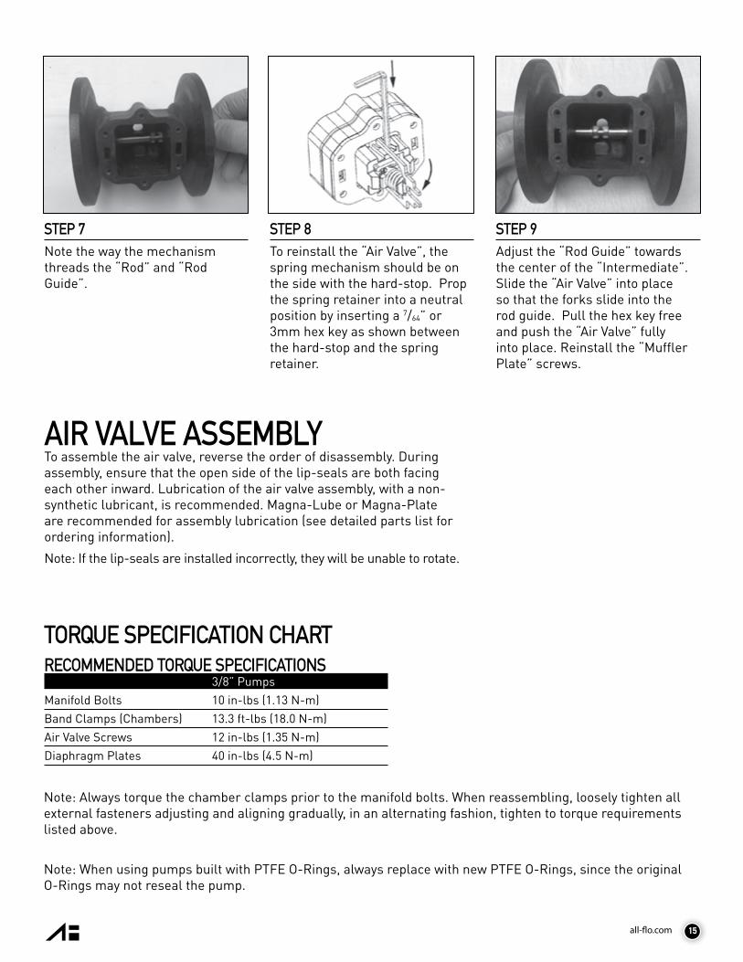
STEP 7 Note the way the mechanism threads the “Rod” and “Rod Guide”.
STEP 8 To reinstall the “Air Valve”, the spring mechanism should be on the side with the hard-stop. Prop the spring retainer into a neutral position by inserting a 7/64” or 3mm hex key as shown between the hard-stop and the spring retainer.
STEP 9 Adjust the “Rod Guide” towards the center of the “Intermediate”. Slide the “Air Valve” into place so that the forks slide into the rod guide. Pull the hex key free and push the “Air Valve” fully into place. Reinstall the “Muffler Plate” screws.
AIR VALVE ASSEMBLYTo assemble the air valve, reverse the order of disassembly. During assembly, ensure that the open side of the lip-seals are both facing each other inward. Lubrication of the air valve assembly, with a non-synthetic lubricant, is recommended. Magna-Lube or Magna-Plate are recommended for assembly lubrication (see detailed parts list for ordering information).
Note: If the lip-seals are installed incorrectly, they will be unable to rotate.
TORQUE SPECIFICATION CHARTRECOMMENDED TORQUE SPECIFICATIONS
3/8” PumpsManifold Bolts 10 in-lbs (1.13 N-m)Band Clamps (Chambers) 13.3 ft-lbs (18.0 N-m)Air Valve Screws 12 in-lbs (1.35 N-m)Diaphragm Plates 40 in-lbs (4.5 N-m)
Note: Always torque the chamber clamps prior to the manifold bolts. When reassembling, loosely tighten all external fasteners adjusting and aligning gradually, in an alternating fashion, tighten to torque requirements listed above.
Note: When using pumps built with PTFE O-Rings, always replace with new PTFE O-Rings, since the original O-Rings may not reseal the pump.

all-flo.com16
EXPLODED VIEW & PARTS LISTC038-SQ*-****-*** CLAMPED PLASTIC
SECTION 8

all-flo.com
PARTS LIST - CLAMPED PLASTICC038-SQ*-****-***ITEM DESCRIPTION QTY PUMP MODEL PART NO. MATERIAL1 ROD GUIDE 1 ALL MODELS 12807-31 Acetal2 AIR VALVE ASSEMBLY 1 ALL MODELS 40380-54 Various3 HEX NUT (1/4” – 20) 4 ALL MODELS (NON-PTFE COATED) 12600-26 Stainless Steel4 FLAT WASHER 8 ALL MODELS (NON-PTFE COATED) 12300-26 Stainless Steel5 DIAPHRAGM ROD 1 ALL MODELS 10316-26 Stainless Steel6 CLAMP (Complete with fasteners) 2 ALL MODELS (NON-PTFE COATED) 12913-26 Stainless Steel7 HEX HUT (5/16” - 18) 4 ALL MODELS (NON-PTFE COATED) 12601-26 Stainless Steel8 CARRIAGE BOLT (5/16” x 1-1/2”) 4 ALL MODELS (NON-PTFE COATED) 12509-26 Stainless Steel 9 SCREW (#8 x 1-3/4”) 6 ALL MODELS (NON-PTFE COATED) 12548-26 Stainless Steel10 PIPE PLUG, 3/8” NPT 2 C038-SPP-****-*** 12206-40 Polypropylene
C038-SPY-****-*** 12206-42 Nylon C038-SPK-****-*** 12206-56 PVDF
11 SUCTION MANIFOLD 1 C038-SPP-****-*** 10570-40 Polypropylene C038-SPY-****-*** 10570-46 Conductive Nylon
C038-SPK-****-*** 10570-56 PVDF12 O-RING, VALVE SEAT 4 C038-SP*-***N-*** 11938-11 Nitrile
C038-SP*-***E-*** 11938-15 EPDM C038-SP*-***T-*** 11938-17 PTFE C038-SP*-***V-*** 11938-82 Viton®/FKM
16 OUTER CHAMBER 2 C038-SPP-****-*** 10701-40 Polypropylene C038-SPY-****-*** 10701-46 Conductive Nylon
C038-SPK-****-*** 10701-56 PVDF17 OUTER DIAPHRAGM PLATE 2 C038-SPP-****-*** 11201-40 Polypropylene
C038-SPY-****-*** 11201-46 Conductive Nylon C038-SPK-****-*** 11201-56 PVDF
18 DIAPHRAGM (PTFE ONLY) 2 C038-SP*-T***-*** 11401-59 PTFE19 DIAPHRAGM 2 C038-SP*-G***-*** 10601-19 Geolast®
C038-SP*-S***-*** 10601-23 Santoprene®20 DISCHARGE MANIFOLD 1 C038-SPP-****-*** 10571-AF-40 Polypropylene
C038-SPY-****-*** 10571-AF-46 Conductive Nylon C038-SPK-****-*** 10571-AF-56 PVDF
21 INNER DIAPHRAGM PLATE 2 ALL MODELS 11101-25 Plated Steel22 INTERMEDIATE 1 ALL MODELS 11503-60 Polypropylene23 CAP SCREW 4 ALL MODELS (NON-PTFE COATED) 12515-26 Stainless Steel24 MUFFLER 1 ALL MODELS 13008-00 Polypropylene 25 O-RING (Diaphragm, PTFE ONLY) 2 C038-SP*-T***-*** 11942-11 Nitrile26 LIP SEAL 2 ALL MODELS 12005-76 Nitrile27 BALL CAGE 4 C038-SPP-****-*** 10914-40 Polypropylene
C038-SPY-****-*** 10914-46 Conductive Nylon C038-SPK-****-*** 10914-56 PVDF
28 VALVE SEAT 4 C038-SP*-**3*-*** 10913-26 Stainless Steel C038-SP*-**P*-*** 10913-40 Polypropylene C038-SP*-**K*-*** 10913-56 PVDF
29 BALL 4 C038-SP*-*V**-*** 11000-13 Viton®/FKM C038-SP*-*G**-*** 11000-19 Geolast® C038-SP*-*S**-*** 11000-23 Santoprene® C038-SP*-*T**-*** 11000-45 PTFE
* Any Character
17

all-flo.com
ASSEMBLY PART NUMBERS PUMP MODEL PART NO. MATERIALWET END ASSEMBLY ALL MODELS CWE-SQ*-****-*** VARIOUS
19, 29, 28, 12
PARTS LIST - CLAMPED PLASTICC038-SQ*-****-***

all-flo.com18
SECTION 9
ELASTOMERS
VITON® is an elastomer with good corrosion resistance to a wide variety of chemicals. Temperature range -40°F to 350°F (-40C to 177C).
PTFE (POLYTETRAFLUOROETHYLENE)is a thermoplastic polymer that is inert to most chemicals. Similar in chemical resistance to Teflon®. Temperature range 40°F to 220°F (4C to 104C).
Most of the above elastomers are available in FDA approved formulations.
BUNA-N (NITRILE)is a general purpose elastomer used with water and many oils. Temperature range 10°F to 180°F (-12C to 82C).
GEOLAST® is an injection molded thermoplastic material with characteristics similar to Nitrile. Has excellent abrasion resistance. Temperature range 10°F to 180°F (-12C to 82C).
EPDM is a general purpose elastomer with good resistance to many acids and bases. Temperature range -40°F to 280°F (-40C to 138C).
SANTOPRENE® is an injection molded material with characteristics similar to EPDM. Has excellent abrasion resistance. Temperature range -40°F to 225°F (-40C to 107C).
FKMis an elastomer with good corrosion resistance to a wide variety of chemicals. Similar in chemical resistance to Viton®. Temperature range -40°F to 350°F (-40C to 177C).
WETTED ELASTOMERS
II 2 GD c TX
Warning: The TX marking refers to the maximum surface temperature depending not on the equipment itself, but mainly on operating conditions. In this case, the maximum surface temperature depends upon the temperature of the process fluids.
Viton® is a registered trademark of DuPont Performance Elastomers L.L.C.Geolast® is a registered trademark of ExxonMobil Chemical Co.Santoprene® is a registered trademark of ExxonMobil Chemical Co.Teflon® is a registered trademark of DuPont Performance Elastomers L.L.C.Hytrel® is a registered trademark of DuPont Performance Elastomers L.L.C.Magnalube® is a registered trademark of Carleton-Stuart Corp.

all-flo.com 19
WARRANTY. All All-Flo products shall be covered by the standard All-Flo Limited Warranty in effect at the time of shipment. This warranty (which may be modified by All-Flo at any time) provides:
MATERIALS SOLD ARE WARRANTED TO THE ORIGINAL USER AGAINST DEFECTS IN WORKMANSHIP OR MATERIALS UNDER NORMAL USE (RENTAL USE EXCLUDED) FOR FIVE YEARS AFTER PURCHASE DATE. ANY PUMP WHICH IS DETERMINED TO BE DEFECTIVE IN MATERIAL AND WORKMANSHIP AND RETURNED TO ALL-FLO, SHIPPING COSTS PREPAID, WILL BE REPAIRED OR REPLACED AT ALL-FLO’S OPTION. CUSTOMER SHALL NOTIFY ALL-FLO IN WRITING WITHIN 30 DAYS OF ANY CLAIMED DEFECTS. NO MATERIALS CAN BE RETURNED WITHOUT THE PRIOR CONSENT OF ALL-FLO, AND IF APPROVED SHALL BE RETURNED TO ALL-FLO FREIGHT PREPAID. ALL-FLO’S LIABILITY FOR ANY BREACH OF THIS WARRANTY SHALL BE LIMITED TO EITHER REPLACEMENT OF THE MATERIALS OR, AT ALL-FLO’S SOLE OPTION, THE REFUND OF THE PURCHASE PRICE. ALL-FLO SHALL NOT BE HELD LIABLE FOR ANY INCIDENTAL OR CONSEQUENTIAL DAMAGES CAUSED BY BREACH OF THIS WARRANTY. THIS EXCLUSION APPLIES WHETHER SUCH DAMAGES WERE SOUGHT BASED ON BREACH OF WARRANTY, BREACH OF CONTRACT, NEGLIGENCE, STRICT LIABILITY IN TORT, OR ANY OTHER LEGAL THEORY. FURTHER, ALL-FLO SHALL NOT BE LIABLE FOR LOSSES, DELAYS, LABOR COSTS, OR ANY OTHER COST OR EXPENSE DIRECTLY OR INDIRECTLY ARISING FROM THE USE OF MATERIALS. ALL-FLO’S LIABILITY IS EXPRESSLY LIMITED TO THE REPLACEMENT OR REPAIR OF DEFECTIVE GOODS, OR THE TOTAL VALUE OF SUCH GOODS. THIS WARRANTY IS IN LIEU OF ALL OTHER WARRANTIES, WHETHER EXPRESS, IMPLIED, OR ORAL INCLUDING THE IMPLIED WARRANTY OF MERCHANTABILITY, ANY IMPLIED WARRANTY OF FITNESS FOR A PARTICULAR PURPOSE, AND ANY IMPLIED WARRANTIES OTHERWISE ARISING FROM A COURSE OF DEALING OR TRADE. All-Flo will not, in ANY event, be liable for any loss of profit, interruption of business or any other special, consequential or incidental damages suffered or sustained by Customer. All-Flo’s total maximum liability to the customer in respect of sale of materials or services rendered by All-Flo is limited to the total monies received by All-Flo from the customer for the particular materials described in Customer’s order.
All-Flo does not warrant any part or component that it does not manufacture, but will assign to the original end-user purchaser of any warranty received by it from the manufacturer, to extent such pass through is permitted by the manufacturer.
REGISTRATION FORMPump Model _________________________________ Pump Serial Number __________________________
Company Name _____________________________________________________________________________
Name ______________________________________ Email _______________________________________
Phone # ____________________________ City _____________________ State ______ Zip ___________
Qty of Pumps ________________________________ Fluid Pumping _______________________________
How did you hear about us? Existing All-Flo user, Web, Distributor, Magazine…
______________________________________________________
www.all-flo.com/registration-form.html
WARRANTY AND REGISTRATION
MAIL TO: All-Flo Pump Co. | Attn: Product RegistrationPO BOX 1870 | Mentor, OH 44061
Scan QR code and complete form on mobile phone or visit
10SECTION

all-flo.com
7750 Tyler Blvd.Mentor, Ohio 44060
phone: 440.354.1700fax: 440.354.9466
all-flo.com
13966-C038-P_Rev_B1
ALL-FLO is committed to the pursuit of designing and manufacturing the highest quality product available to industry. Since the beginning in 1986, All-Flo engineers have used their extensive knowledge of today’s engineered materials, advanced air system logic and manufacturing techniques to develop the superior group of lube-free, air-operated diaphragm pumps found in this catalog. Every pump is performance engineered and quality built to provide trouble-free service under the toughest conditions.