Embed Size (px)
Citation preview
Pumps for Applying Crop Protection Products
Kansas State University Agricultural Experiment Station and Cooperative Extension Service
Robert E. Wolf, Extension Specialist, Biological and Agricultural Engineering, Kansas State University Application Technology Series
IntroductionA pump is the heart of the sprayer and a key
component for producing the flow of spray mate-rial and sprayer output. Because various spraying situations require different pressures and flow rates, using the correct sprayer pump is essential to achiev-ing desired results. In addition to sprayer consid-erations, a pump must also be durable enough to withstand harsh chemicals that may cause excessive wear. Even though pumps with added chemical corrosion protection are more expensive, they are a popular choice because of their durability.
Roller, centrifugal, diaphragm, and piston pumps are commonly used to apply crop protection prod-ucts. Centrifugal and roller pumps are typically used for low-pressure sprayers, and diaphragm and piston pumps are more popular when high-pressure sprayers are needed (i.e., vegetables, orchards, etc.). Less com-mon pump types include squeeze, gear, and turbine.
Pumps are typically either ground driven or powered by main or auxiliary engines, power take-off (PTO) shafts, or hydraulic pumps. The choice of pump depends on the material to be pumped and the capacity or volume needed. However, no par-ticular type of pump is ideal for all purposes.
Sprayer pumps can be divided into two general categories: positive displacement and non-positive displacement. Positive displacement pumps (roller, diaphragm, and piston) maintain a flow output di-rectly proportional to the pump speed. These pumps require a pressure-relief valve and a bypass line for proper performance. Non-positive displacement pumps do not have a proportional output flow to pump speed and do not require a relief valve and bypass line. The centrifugal pump is an example of a non-positive displacement pump style. A summary of common pump types and characteristics is found in Table 1 (page 2).
Pump EfficiencyRegardless of the type of pump, the necessary
flow rate must be provided at the desired pressure. Enough spray liquid should be pumped to sup-ply the gallons per minute (gpm) required by the nozzles and the tank agitator, with a reserve capac-ity of 10 to 20 percent to allow for flow loss as the pump becomes worn.
Unfortunately, pumps lose efficiency for a number of reasons, such as drive friction or leakage. When estimating the pump horsepower needed for an application, efficiency (Eff) of 40 to 60 percent should be assumed. The horsepower (HP) required to drive the pump can be estimated by using the following formula:
HP = gpm × psi *1,714 × Eff*Constant derived when converting gallons,
minutes, pounds, and inches to horsepower.Example: How much horsepower is required to
run a pump if the maximum output is 50 gpm at 40 pounds per square inch (psi)? Assume a pump efficiency of 40 percent.
HP = 50 gpm × 40 psi = 2.92 1,714 × 0.40 Eff
Because of inefficiencies of the drive units, elec-tric motors should be approximately one third larger than the calculated horsepower. Gasoline engines should be one half to two thirds larger than the pump horsepower required. Ground-driven pumps that vary flow rates as ground speed changes are accurate and dependable; they are often used when applying high volumes of materials such as fertilizer.
Many pumps are PTO driven, but most modern spray pumps are hydraulic driven because of mount-ing versatility, ease of maintenance, and customiza-tion for individual sprayers. Charts are available to

2
Pum
p Ty
pes
Char
acte
rist
ics
Rolle
rCe
ntri
fuga
lD
iaph
ragm
Pist
onG
roun
d D
rive
n Pi
ston
Pum
psCo
stLo
wH
igh
Med
ium
Hig
hH
igh
Dis
plac
emen
tPo
sitiv
e, s
elf-p
rimin
g;
Requ
ires
relie
f val
veN
on-p
ositi
ve, n
eeds
prim
ed;
Relie
f val
ve n
ot re
quire
dPo
sitiv
e, s
elf-
prim
ing;
Re
quire
s re
lief
valv
e
Posi
tive,
se
lf-pr
imin
g;
Requ
ires
relie
f val
ve
Posi
tive,
sel
f prim
ing;
relie
f val
ve n
ot
requ
ired.
Run
s off
of d
rive
whe
el a
nd
can
be li
fted
on
hydr
aulic
-con
trol
led
appl
icat
ors
or c
an b
e pu
rcha
sed
with
cl
utch
es to
dis
enga
ge p
ump
whe
n flo
w is
not
des
ired.
Dri
ve M
echa
nism
PTO
, gas
eng
ine
driv
es,
elec
tric
mot
ors
PTO
, hyd
raul
ic, g
as e
ngin
es,
elec
tric
mot
ors
PTO
, hyd
raul
ic,
gas
engi
nes
PTO
, gas
eng
ines
, el
ectr
ic m
otor
sPr
imar
ily g
roun
d dr
iven
. Alth
ough
less
co
mm
on, c
an b
e us
ed w
ith h
ydra
ulic
dr
ives
, ele
ctric
mot
ors,
or g
as e
ngin
es.
Ada
ptab
ility
Com
pact
and
ver
satil
eG
ood
for a
bras
ive
mat
eria
ls;
Han
dles
sus
pens
ions
and
sl
urrie
s w
ell;
N
eeds
hig
her r
pm
Com
pact
for
amou
nt o
f flow
an
d pr
essu
re
deve
lope
d
Wid
e ra
nge
of sp
ray-
ing
appl
icat
ions
; D
epen
dabl
e
Wid
e ra
nge
of s
pray
ing
appl
icat
ions
fr
om c
lear
liqu
ids
to s
uspe
nsio
ns. V
ery
accu
rate
rega
rdle
ss o
f gro
und
spee
d or
bac
k pr
essu
re. V
ery
depe
ndab
le.
Dur
abili
tyPa
rts
to w
ear,
repl
ace
Very
dur
able
, not
muc
h w
ear
No
corr
osio
n of
in
tern
al p
arts
Part
s to
wea
r, re
plac
eVe
ry d
urab
le. W
ith b
asic
car
e an
d m
aint
enan
ce, p
umps
can
eas
ily b
e in
se
rvic
e fo
r 30
year
s or
mor
e.
Serv
icea
bilit
yEa
sy to
wor
k on
, rep
air
Basi
c m
aint
enan
ce e
xten
ds
life
Low
mai
nten
ance
Pote
ntia
l for
hig
h m
aint
enan
ceLo
w m
aint
enan
ce
Pres
sure
Ran
geU
p to
300
psi
Up
to 1
80 p
siU
p to
725
psi
Up
to 4
00 p
siU
p to
120
psi
Out
put V
olum
e2
to 7
4 gp
m;
Hig
h vo
lum
es fo
r siz
e;
Prop
ortio
nal t
o pu
mp
spee
d
Up
to 1
90 g
pm;
Hig
h vo
lum
es fo
r siz
e an
d w
eigh
t; Pr
opor
tiona
l to
pum
p sp
eed
3.5
to 6
6 gp
m;
Prop
ortio
nal t
o pu
mp
spee
d
Low
, up
to 1
0 gp
m;
Prop
ortio
nal t
o pu
mp
spee
d, in
de-
pend
ent o
f pre
ssur
e
0.5
gpm
and
up
to 6
8.4
gpm
Revo
luti
ons
per
min
ute
540,
100
0Re
quire
s sp
eed-
up
mec
hani
sm.
Very
effi
cien
t at h
ighe
r sp
eeds
; U
p to
600
0 rp
m
540
540
Gro
und
driv
en. M
axim
um 4
50 rp
m
Not
esBe
st c
hoic
e by
farm
ers
If hy
drau
lic d
riven
, no
PTO
re
quire
d.
Popu
lar i
n co
mm
erci
al
agric
ultu
ral a
pplic
atio
ns.
Runn
ing
pum
p dr
y is
a
prob
lem
.
Goo
d fo
r hig
her
pres
sure
requ
ire-
men
ts.
Popu
lar f
or h
orti-
cultu
ral a
pplic
a-tio
ns. P
ump
can
run
dry.
Sim
ilar t
o an
eng
ine;
Lo
w c
apac
ityN
o gp
a flo
w v
aria
tion
due
to p
ress
ure
or g
roun
d sp
eed
chan
ges.
No
conc
ern
of e
lect
roni
c fa
ilure
s on
con
trol
lers
or
rada
r sys
tem
s, ju
st d
epen
dabl
e ac
-cu
racy
eve
ry ti
me.
Robe
rt E
. Wol
f, Ka
nsas
Sta
te U
nive
rsity
. Con
trib
utio
ns a
lso
from
ACE
Pum
ps C
orpo
ratio
n, H
ypro
Pum
ps, I
nc.,
and
CDS-
John
Blu
e Co
mpa
ny.
Tabl
e 1.
Com
mon
Pum
p Ty
pes
and
Char
acte
ristic
s fo
r Spr
ayer
s.

3
match pumps to various tractor hydraulic systems. Refer to Table 2 for Web page addresses of major pump manufacturers for access to these charts.
Pump CapacityProper pump size is an important consideration
when selecting a sprayer pump. Requirements for nozzle capacity, hydraulic agitation, and overcom-ing the efficiency loss noted previously are essential points to consider. Nozzle capacity is determined by multiplying the number of nozzles on the boom times the output (gpm) of each nozzle for a specific application. Be sure to give consideration to the range of spray pressures that will be used for the given application. Agitation requirements typi-cally account for another 5 percent of the sprayer tank capacity. Efficiency losses due to friction and pump wear may account for an additional 10 to 20 percent increase in the required flow rate. Spray pump manufacturers provide useful Web page worksheets to help determine pump sizes based on typical field application scenarios. Manufacturers also make product guides available to help match sprayer pumps and hydraulic motors to the tractor’s hydraulic system (Table 2). A simple pump selection worksheet is provided on page 7 of this publication.
No matter what type pump is used, it must be plumbed to route liquid from the pump to the spray boom with a minimum amount of restriction, a necessity for achieving the pump’s maximum rated capacity. The hoses should be the same size as the pump’s suction and discharge ports. Other recom-mendations include installing a pressure gauge and valve on the pressure side of the pump to measure the
shut-off pressure and using a minimum number of elbows, fittings, and valves to reduce pressure losses. Following these guidelines is necessary for delivering the highest pressures to the boom.
Pump RotationPump rotation is critical for PTO and belt-
and-pulley driven pumps. The direction of rotation is always determined when facing the pump and drive shaft, and pumps are available in both clock-wise and counterclockwise rotation. Thus, when direct coupling shafts, the opposite rotation pump should always match the shaft. When mounting a pump with belts and pulleys, either pump rotation can be used to match the drive shaft rotation and the desired direction of the pump. Gasoline engine and electric motor shafts rotate in a counterclock-wise direction, and a tractor PTO shaft rotates in a clockwise direction.
Pump TypesRoller pumps are popular for small sprayers
because of their low initial cost, compact size, ease of repair, and efficient operation at PTO speeds of 540 and 1000 revolutions per minute (rpm). Roller pumps are self-priming, positive displacement pumps, and a variety of models is available. Maxi-mum outputs range from 2 to 75 gpm, and pres-sures range up to 300 psi.
Roller pumps are usually constructed with cast iron or corrosion resistant housings (non-symmet-rical in shape), rotors, four to eight rollers (either nylon, Teflon, or rubber), and seals (Viton, rubber, or leather). The type of material selected depends on the chemical being pumped. A typical roller pump is shown in Figure 1 (page 4).
Nylon or Teflon rollers are the most resistant to agricultural chemicals and are recommended for multipurpose sprayers. Rubber rollers are preferred when the pump is used only for water solutions and wettable powder slurries at pressures less than 100 psi. Because sand and scale are abrasive to the rollers, the solution being pumped must not contain these ma-terials. Polypropylene rollers wear better than either nylon or rubber rollers when applying weak solutions or solutions with little or no lubricating qualities.
Table 2. Selected agricultural pump manufacturer Web sites.
Hypro Pumps www.hypropumps.com
ACE Pump Corporation www.acepumps.com
CDS-John Blue Company www.cds-johnblue.com
Hardi – North America www.hardi-us.com
Delavan Ag Spray www.delavanagspray.com
Watson-Marlow www.watson-marlow.com

4
Some operators have experienced problems with excessive wear of the rollers, especially when using wettable powders. Other operators have achieved long pump life by allowing the pump to run con-tinuously when spraying with wettable powders, and by properly maintaining and storing the pump, including keeping abrasive materials out of the sprayer. Specific seal, roller, and casting materi-als can be selected for compatibility with certain herbicides, insecticides, fungicides, and fertilizers. Consideration should also be given to the adjuvants used in the spray solution.
Centrifugal pumps are the most popular type of low-pressure sprayer. They are durable, simply constructed, and can readily handle wettable pow-ders and abrasive materials. Because of the high output of centrifugal pumps (70 to 190 gpm), the spray solution can be agitated sufficiently even in large tanks at pressures up to 180 psi. The initial cost of a centrifugal pump is somewhat higher
than that of a roller pump, but its long life and low maintenance make it an economical choice. Pump housings of cast iron, stainless steel, and polypropyl-ene are advantageous because they withstand strong chemicals. Stainless steel pumps are ideal for use with glyphosate or other acid applications. Polypro-pylene pumps are lightweight and provide excellent resistance to corrosive chemicals. Figure 2 shows a typical centrifugal pump.
Because centrifugal pumps are not self-priming, they should be mounted below the supply tank to aid in priming. In addition, a small vent tube should be installed from the top of the pump housing to the supply tank. This positive vent line allows the pump to prime itself by “bleeding off” trapped air upon starting and when the pump is not operating.
The inlet of a centrifugal pump should never be restricted. A partially clogged suction strainer, collapsed suction line, or a suction line with insuf-ficient capacity causes a loss of pressure control and possible damage to the pump. Centrifugal pumps can handle small pieces of foreign material without damage, so a suction strainer is not always required. If a suction strainer is used, however, it must be capable of handling the large capacities of the pump with a minimal drop in pressure across the strainer, and it must be cleaned frequently. Typical centrifu-gal pump plumbing would place the strainer on the pressure side of the pump.
Centrifugal pumps for low-pressure sprayers can generate pressures of up to 70 psi when the
BearingShaft
Seal
Roller
Rotor
Inlet port
Casing
Casing
Exit port
Figure 1. Roller pump and cutaway
Figure 2. Centrifugal pump and cutaway
Figure 3. Centrifugal pump performance curve
Bearing
SealShaft
Impeller
Outlet port
Inlet port
VentCasing
Bode and Butler, 1981, Circular 1192. University of Illinois
5
impellers are running between 3,000 and 4,500 rpm. The output volume drops off rapidly when the outlet pressure exceeds 30 to 40 psi. The decrease in volume is an advantage because the nozzle pressure is able to be controlled without a relief valve. See Figure 3 for a typical centrifugal pump performance curve. The pump performance curve describes the relationship between flow rate and pressure for the actual pump.
The need to operate at high impeller speeds requires a type of step-up speed mechanism when operating centrifugal pumps from PTO shafts. The simplest and least expensive of these mechanisms is a belt and sheave assembly. Other step-up mecha-nisms have planetary gears that are completely enclosed and mounted directly on the PTO shaft.
Another method of driving a centrifugal pump is with a close coupled, high speed hydrau-lic motor. Using the tractor hydraulic system to drive the pump keeps the tractor PTO shaft free for other uses. It is essential to consult manufac-turer pump selection guides to match the proper pump to your tractor. Pumps can also be driven by direct-coupled gasoline engines when other drive mechanisms cannot be used.
Airplane pumps may be wind-driven, directly powered from the aircraft engine, or powered by an electric or hydraulic motor. The pump may also pow-er the tank agitation system. For fixed-wing aircraft, the most common type of pump is a wind-driven
centrifugal pump mounted under the aircraft (Figure 4). The propeller slipstream drives a fan mounted on the front of the pump. Some fan-driven pumps have variable pitch blades that allow for changing pump speed, and thus output. The centrifugal pumps com-monly used on aircraft produce high volumes (up to 200 gpm) at typically low pressure, usually ranging between 10 and 100 psi. These pumps usually require operating speeds from 1,000 to 5,000 rpm.
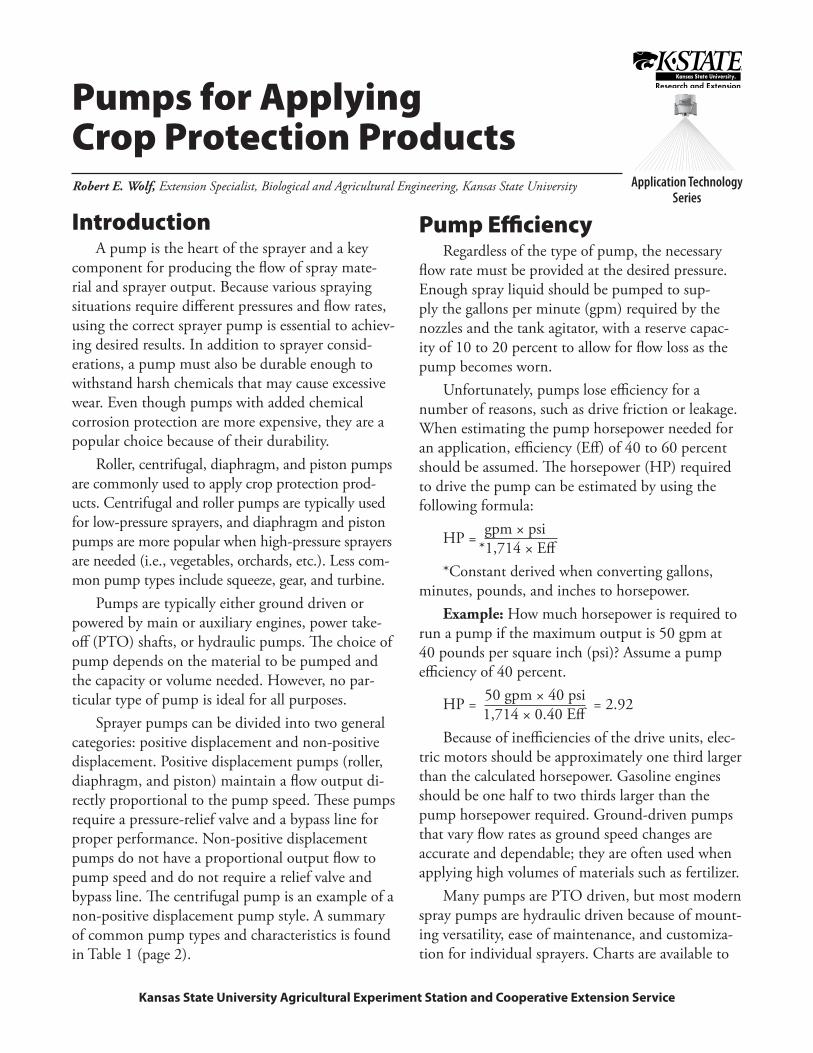
Diaphragm pumps are popular when higher pressures are needed for applying foliar herbicides, insecticides, and fungicides. Models are available that provide maximum outputs ranging from 3.5 to 60 gpm and maximum pressures ranging from 200 to 700 psi. These pumps are extremely durable be-cause all moving parts are sealed in an oil bath and
Figure 4. Airplane pump Figure 5. Diaphragm pump and cutaway
Figure 6. Electric diaphragm pump and cutaway
Fan blade
Housing
Inlet
Outlet
Pulsationdamper
coverPulsationdamper
diaphragmBody
Cylinder sleeve
Diaphragm
Head
Motor
Drive/Impeller diaphragm assemblyInlet
Outlet
Switch assembly
Upper housing
Bypass/Non-bypass valve assembly
6
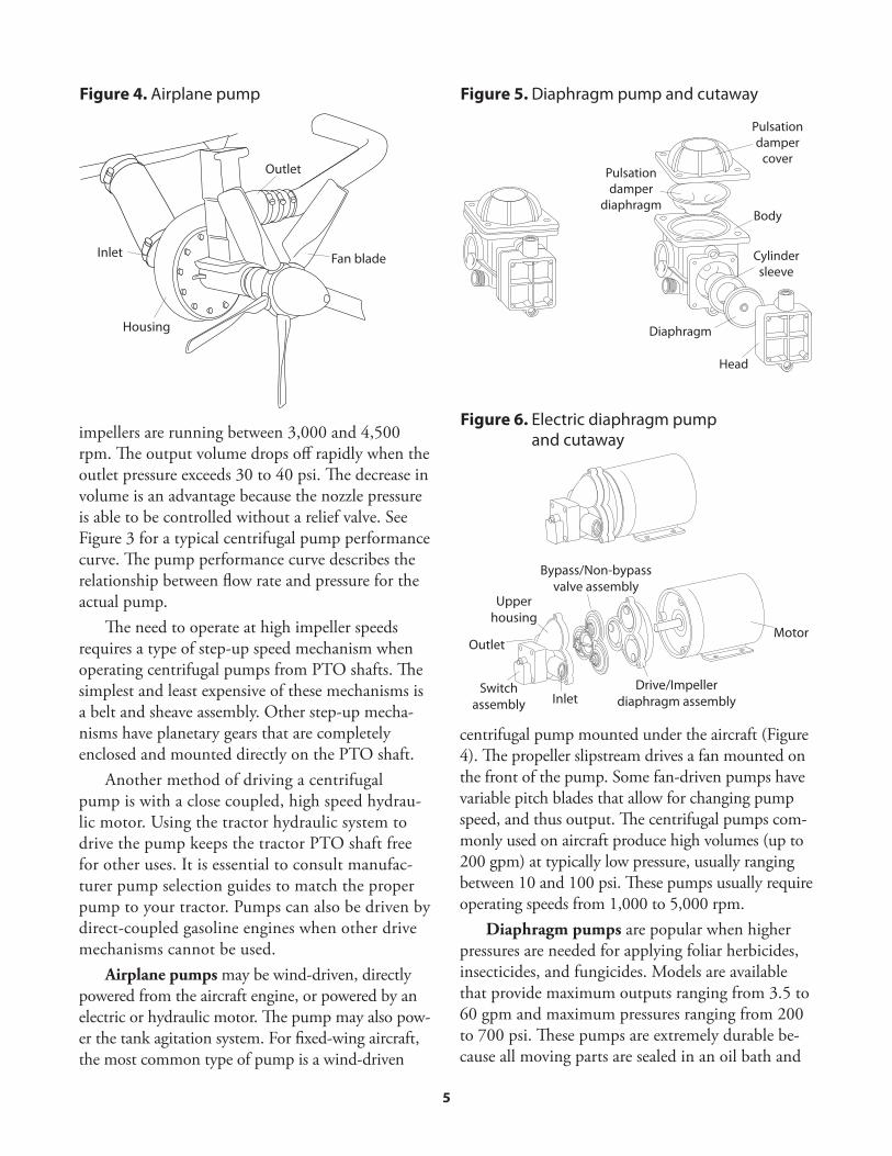
do not come in contact with corrosive and abrasive spray solutions. Diaphragm pumps are self-priming and considered positive displacement pumps. Figure 5 (page 5) shows a typical diaphragm pump. Smaller electric diaphragm pumps (Figure 6, page 5)) are available for use by homeowners, ranchers, and hobbyists to apply pest control products. A good example is a spray system mounted on an ATV for spraying pastures and rights-of-way.
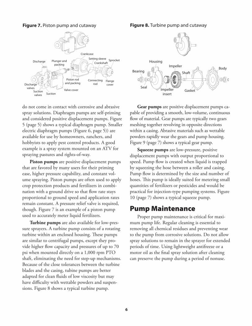
Piston pumps are positive displacement pumps that are favored by many users for their priming ease, higher pressure capability, and constant vol-ume spraying. Piston pumps are often used to apply crop protection products and fertilizers in combi-nation with a ground drive so that flow rate stays proportional to ground speed and application rates remain constant. A pressure relief valve is required, though. Figure 7 is an example of a piston pump used to accurately meter liquid fertilizers.
Turbine pumps are also available for low-pres-sure sprayers. A turbine pump consists of a rotating turbine within an enclosed housing. These pumps are similar to centrifugal pumps, except they pro-vide higher flow capacity and pressures of up to 70 psi when mounted directly on a 1,000 rpm PTO shaft, eliminating the need for step-up mechanisms. Because of the close tolerances between the turbine blades and the casing, tubine pumps are better adapted for clean fluids of low viscosity but may have difficulty with wettable powders and suspen-sions. Figure 8 shows a typical turbine pump.
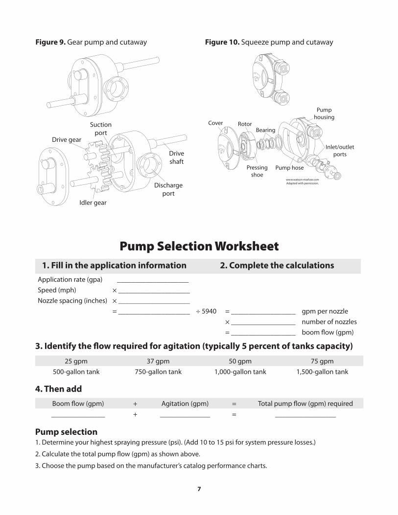
Gear pumps are positive displacement pumps ca-pable of providing a smooth, low-volume, continuous flow of material. Gear pumps are typically two gears meshing together revolving in opposite directions within a casing. Abrasive materials such as wettable powders rapidly wear the gears and pump housing. Figure 9 (page 7) shows a typical gear pump.
Squeeze pumps are low-pressure, positive displacement pumps with output proportional to speed. Pump flow is created when liquid is trapped by squeezing the hose between a roller and casing. Pump flow is determined by the size and number of hoses. This pump is ideally suited for metering small quantities of fertilizers or pesticides and would be practical for injection-type pumping systems. Figure 10 (page 7) shows a typical squeeze pump.
Pump MaintenanceProper pump maintenance is critical for maxi-
mum pump life. Regular cleaning is essential to removing all chemical residues and preventing wear to the pump from corrosive solutions. Do not allow spray solutions to remain in the sprayer for extended periods of time. Using lightweight antifreeze or a motor oil as the final spray solution after cleaning can preserve the pump during a period of nonuse.
Valve coverSuction
Sprocket
Connecting rod
Flange cover
Crankcase
CrankshaftSetting sleeve
Discharge Plunger and packing
Piston rod and packingDischarge
valvesSuction valves
Figure 7. Piston pump and cutaway Figure 8. Turbine pump and cutaway
Bearing
Seal
Housing
Impeller insert
Impeller
Shaft
Gasket
Body
7
Figure 9. Gear pump and cutaway
Drive gear
Idler gear
Drive shaft
Discharge port
Suction port
Figure 10. Squeeze pump and cutaway
Cover
www.watson-marlow.comAdapted with permission.
Rotor
Pressing shoe
Pump hose
Pump housing
Inlet/outlet ports
Bearing
Pump Selection Worksheet1. Fill in the application information 2. Complete the calculations
Application rate (gpa) ____________________Speed (mph) × ____________________Nozzle spacing (inches) × ____________________
= ____________________ ÷ 5940 = __________________ gpm per nozzle× __________________ number of nozzles= __________________ boom flow (gpm)
3. Identify the flow required for agitation (typically 5 percent of tanks capacity)
4. Then add
Pump selection1. Determine your highest spraying pressure (psi). (Add 10 to 15 psi for system pressure losses.)
2. Calculate the total pump flow (gpm) as shown above.
3. Choose the pump based on the manufacturer’s catalog performance charts.
Boom flow (gpm) + Agitation (gpm) = Total pump flow (gpm) required_______________ + ______________ = _________________
25 gpm 37 gpm 50 gpm 75 gpm500-gallon tank 750-gallon tank 1,000-gallon tank 1,500-gallon tank

Publications are reviewed or revised annually by appropriate faculty to reflect current research and practice. Date shown is that of publication or last revision.
Brand names appearing in this publication are for product identification purposes only. No endorsement is intended, nor is criticism implied of similar products not mentioned.
Publications from Kansas State University are available on the World Wide Web at: www.ksre.ksu.eduContents of this publication may be freely reproduced for educational purposes. All other rights reserved. In each case, credit
Robert E. Wolf, Pumps for Applying Crop Protection Products, Kansas State University, March 2010.
Kansas State University Agricultural Experiment Station and Cooperative Extension ServiceMF2895 March 2010K-State Research and Extension is an equal opportunity provider and employer. Issued in furtherance of Cooperative Extension Work, Acts of May 8 and June 30, 1914, as amended. Kansas State University, County Extension Councils, Extension Districts, and United States Department of Agriculture Cooperating, Gary Pierzynski, Interim Director.
AcknowledgementsExcerpts for this document were adapted with permission from University of Illinois Circular 1192
developed by Loren Bode and Jack Butler (May 1981), Extension Agricultural Engineer and Professor of Agricultural Engineering, University of Illinois at Urbana-Champaign.
Contributions for this document were also received form ACE Pumps Corporation; Hypro Pumps, Inc.; and CDS-John Blue Company.


![NORTA MIT PRESENTATION.pptx [Read-Only] · • Centrifugal pumps • Side channel pumps • Gear pumps • Screw pumps • Single screw pumps • Piston pumps • Vacuum pumps •](https://img.pdfslide.net/doc/110x75/5ec27ab9e3ef591d10504c3a/norta-mit-read-only-a-centrifugal-pumps-a-side-channel-pumps-a-gear-pumps.jpg)