Embed Size (px)
Citation preview
98 · Pure Iron Based Soft Magnetic Composite Core That Enables Downsizing Automotive Reactors
INDUSTRIAL MATERIALS
1. Introduction
Against the backdrop of growing environmental awareness and surging fuel prices in recent years, hybrid electric vehicles (HEVs) and plug-in hybrid elec-tric vehicles (PHEVs), etc. have been increasingly devel-oped in many countries because these vehicles have less environmental impact than conventional vehicles in terms of CO2 emissions and fuel efficiency, etc.
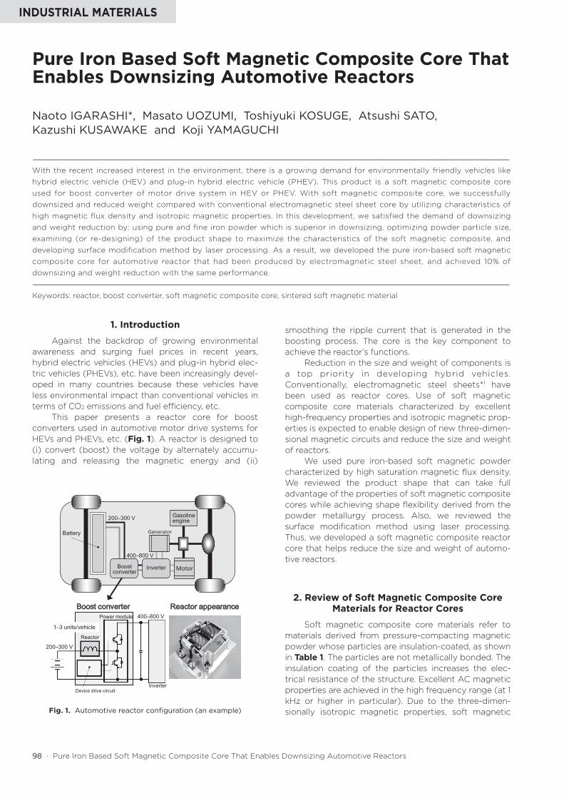
This paper presents a reactor core for boost converters used in automotive motor drive systems for HEVs and PHEVs, etc. (Fig. 1). A reactor is designed to (i) convert (boost) the voltage by alternately accumu-lating and releasing the magnetic energy and (ii)
smoothing the ripple current that is generated in the boosting process. The core is the key component to achieve the reactor’s functions.
Reduction in the size and weight of components is a top priority in developing hybrid vehicles. Conventionally, electromagnetic steel sheets*1 have been used as reactor cores. Use of soft magnetic composite core materials characterized by excellent high-frequency properties and isotropic magnetic prop-erties is expected to enable design of new three-dimen-sional magnetic circuits and reduce the size and weight of reactors.
We used pure iron-based soft magnetic powder characterized by high saturation magnetic flux density. We reviewed the product shape that can take full advantage of the properties of soft magnetic composite cores while achieving shape flexibility derived from the powder metallurgy process. Also, we reviewed the surface modification method using laser processing. Thus, we developed a soft magnetic composite reactor core that helps reduce the size and weight of automo-tive reactors.
2. Review of Soft Magnetic Composite Core Materials for Reactor Cores
Soft magnetic composite core materials refer to materials derived from pressure-compacting magnetic powder whose particles are insulation-coated, as shown in Table 1. The particles are not metallically bonded. The insulation coating of the particles increases the elec-trical resistance of the structure. Excellent AC magnetic properties are achieved in the high frequency range (at 1 kHz or higher in particular). Due to the three-dimen-sionally isotropic magnetic properties, soft magnetic
Pure Iron Based Soft Magnetic Composite Core That Enables Downsizing Automotive Reactors
Naoto IGARASHI*, Masato UOZUMI, Toshiyuki KOSUGE, Atsushi SATO,Kazushi KUSAWAKE and Koji YAMAGUCHI
----------------------------------------------------------------------------------------------------------------------------------------------------------------------------------------------------------------------------------------------------------With the recent increased interest in the environment, there is a growing demand for environmentally friendly vehicles like hybrid electric vehicle (HEV) and plug-in hybrid electric vehicle (PHEV). This product is a soft magnetic composite core used for boost converter of motor drive system in HEV or PHEV. With soft magnetic composite core, we successfully downsized and reduced weight compared with conventional electromagnetic steel sheet core by utilizing characteristics of high magnetic flux density and isotropic magnetic properties. In this development, we satisfied the demand of downsizing and weight reduction by: using pure and fine iron powder which is superior in downsizing, optimizing powder particle size, examining (or re-designing) of the product shape to maximize the characteristics of the soft magnetic composite, and developing surface modification method by laser processing. As a result, we developed the pure iron-based soft magnetic composite core for automotive reactor that had been produced by electromagnetic steel sheet, and achieved 10% of downsizing and weight reduction with the same performance.
----------------------------------------------------------------------------------------------------------------------------------------------------------------------------------------------------------------------------------------------------------Keywords: reactor, boost converter, soft magnetic composite core, sintered soft magnetic material
Reactor appearanceBoost converter
Gasoline engine
Generator
Inverter Motor
200–300 V
400–800 V
200–300 V
400–800 V
Boost converter
Battery
1–3 units/vehicleReactor
Device drive circuit
Power module
Inverter
Fig. 1. Automotive reactor configuration (an example)
SEI TECHNICAL REVIEW · NUMBER 80 · APRIL 2015 · 99
composite core materials are expected to be applied to (i) magnetic components of shapes that are difficult to achieve using conventional electromagnetic steel sheets and (ii) new magnetic components, by means of net shape compacting*2 that is uniquely achieved by the powder metallurgy process.
Table 2 shows the properties required of reactor cores. In recent years, higher output (higher inductance*3) has been required in the market to reduce the size of reactors. Also, higher heat radiation properties and lower energy loss (lower heat generation) have been required to simplify the cooling mechanism and increase the efficiency. Two improvements must be made to meet the above requirements: increasing the magnetic flux density of soft magnetic composite core materials, and lowering the iron loss.
The magnetic flux density B of soft magnetic composite core materials is mostly determined by the material properties of the iron-based soft magnetic powder (base material). In powder metallurgy, iron-based soft magnetic powder is compacted by press forming to manufacture soft magnetic composite core materials. Thus, the magnetic flux density B is also influ-enced by the packing ratio (density) of the iron-based
soft magnetic powder in the structure of soft magnetic composite core materials. To increase the magnetic flux density of the soft magnetic composite core materials, it is necessary to take into consideration not only the saturation magnetic flux density of the iron-based soft magnetic powder (base material) but also the powder compressibility (in terms of powder properties).
The iron loss WB/f (i.e. a property required of powder cores for reactors) is represented by the sum of hysteresis loss (Wh) and eddy current loss (We) in the area where the magnetic flux change in the material is not accompanied by the relaxation phenomena (e.g. magnetic resonance).
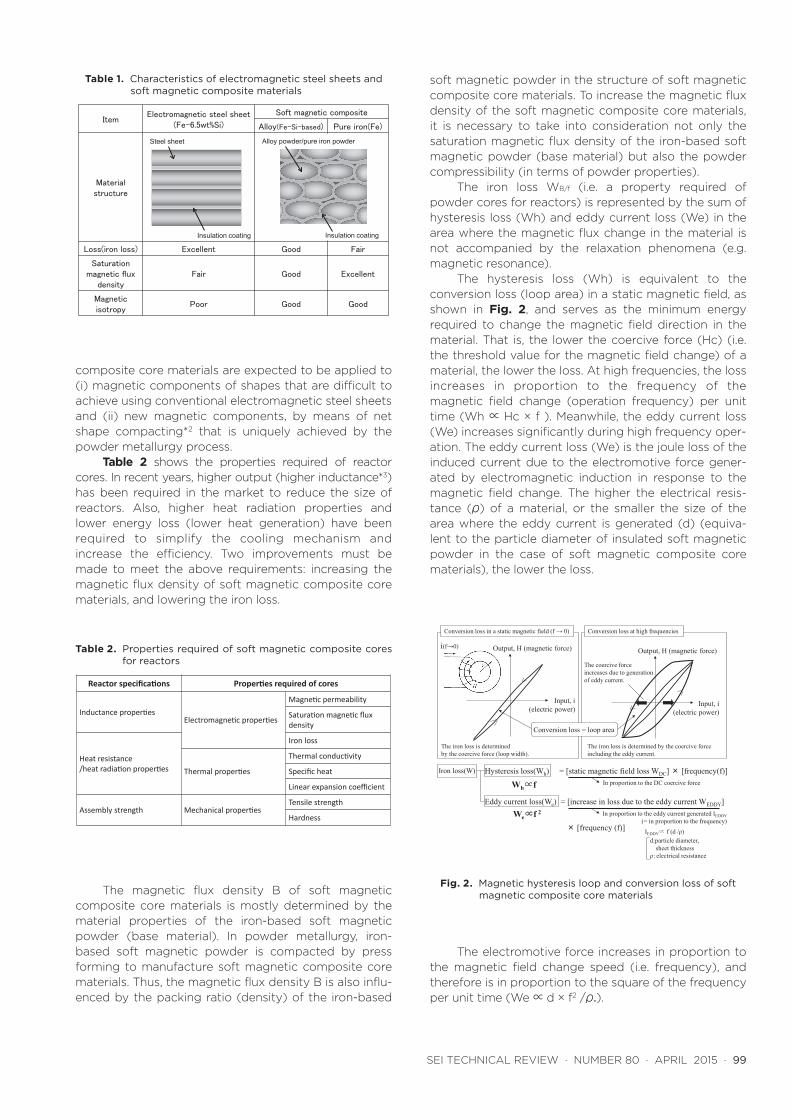
The hysteresis loss (Wh) is equivalent to the conversion loss (loop area) in a static magnetic field, as shown in Fig. 2, and serves as the minimum energy required to change the magnetic field direction in the material. That is, the lower the coercive force (Hc) (i.e. the threshold value for the magnetic field change) of a material, the lower the loss. At high frequencies, the loss increases in proportion to the frequency of the magnetic field change (operation frequency) per unit time (Wh ∝ Hc × f ). Meanwhile, the eddy current loss (We) increases significantly during high frequency oper-ation. The eddy current loss (We) is the joule loss of the induced current due to the electromotive force gener-ated by electromagnetic induction in response to the magnetic field change. The higher the electrical resis-tance (ρ) of a material, or the smaller the size of the area where the eddy current is generated (d) (equiva-lent to the particle diameter of insulated soft magnetic powder in the case of soft magnetic composite core materials), the lower the loss.
The electromotive force increases in proportion to the magnetic field change speed (i.e. frequency), and therefore is in proportion to the square of the frequency per unit time (We ∝ d × f2 /ρ.).
Table 1. Characteristics of electromagnetic steel sheets and soft magnetic composite materials
Table 2. Properties required of soft magnetic composite cores for reactors
ItemElectromagnetic steel sheet
(Fe-6.5wt%Si)
Soft magnetic composite
Alloy(Fe-Si-based) Pure iron(Fe)
Material structure
Loss(iron loss) Excellent Good Fair
Saturationmagnetic flux
densityFair Good Excellent
Magneticisotropy
Poor Good Good
Alloy powder/pure iron powder
Insulation coating
Steel sheet
Insulation coating
Reactor specifications Properties required of cores
Inductance propertiesElectromagnetic properties
Magnetic permeability
Saturation magnetic flux density
Heat resistance/heat radiation properties
Iron loss
Thermal properties
Thermal conductivity
Specific heat
Linear expansion coefficient
Assembly strength Mechanical propertiesTensile strength
Hardness
Input, i(electric power)
Conversion loss = loop area
Conversion loss in a static magnetic field (f → 0)
Output, H (magnetic force)
Hysteresis loss(Wh) = [static magnetic field loss WDC] × [frequency(f)]
Conversion loss at high frequencies
i(f→0)
Iron loss(W)
The coercive forceincreases due to generationof eddy current.
The iron loss is determinedby the coercive force (loop width).
The iron loss is determined by the coercive force including the eddy current.
Eddy current loss(We) = [increase in loss due to the eddy current WEDDY]
In proportion to the DC coercive force
In proportion to the eddy current generated IEDDY(= in proportion to the frequency)
Wh∝f
We∝f 2
IEDDY∝ f (d /ρ)d:particle diameter,
sheet thicknessρ:electrical resistance
Output, H (magnetic force)
Input, i(electric power)
× [frequency (f)]
Fig. 2. Magnetic hysteresis loop and conversion loss of soft magnetic composite core materials
100 · Pure Iron Based Soft Magnetic Composite Core That Enables Downsizing Automotive Reactors
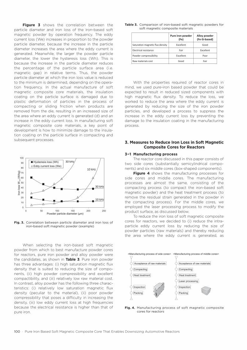
Figure 3 shows the correlation between the particle diameter and iron loss of the iron-based soft magnetic powder by operation frequency. The eddy current loss (We) increases in proportion to the powder particle diameter, because the increase in the particle diameter increases the area where the eddy current is generated. Meanwhile, the larger the powder particle diameter, the lower the hysteresis loss (Wh). This is because the increase in the particle diameter reduces the percentage of the particle surface area (i.e. magnetic gap) in relative terms. Thus, the powder particle diameter at which the iron loss value is reduced to the minimum is determined, depending on the opera-tion frequency. In the actual manufacture of soft magnetic composite core materials, the insulation coating on the particle surface is damaged due to plastic deformation of particles in the process of compacting or sliding friction when products are removed from the die, resulting in an increased size of the area where an eddy current is generated (d) and an increase in the eddy current loss. In manufacturing soft magnetic composite core materials, a key point of development is how to minimize damage to the insula-tion coating on the particle surface in compacting and subsequent processes.
When selecting the iron-based soft magnetic powder from which to best manufacture powder cores for reactors, pure iron powder and alloy powder were the candidates, as shown in Table 3. Pure iron powder has three advantages: (i) high saturation magnetic flux density that is suited to reducing the size of compo-nents, (ii) high powder compressibility and excellent compactibility, and (iii) relatively low raw material cost. In contrast, alloy powder has the following three charac-teristics: (i) relatively low saturation magnetic flux density (peculiar to the material), (ii) poor powder compressibility that poses a difficulty in increasing the density, (iii) low eddy current loss at high frequencies because the electrical resistance is higher than that of pure iron.
With the properties required of reactor cores in mind, we used pure-iron based powder that could be expected to result in reduced sized components with high magnetic flux density. To reduce the loss, we worked to reduce the area where the eddy current is generated by reducing the size of the iron powder particles, and developed a process to suppress the increase in the eddy current loss by preventing the damage to the insulation coating in the manufacturing process.
3. Measures to Reduce Iron Loss in Soft Magnetic Composite Cores for Reactors
3−1 Manufacturing processThe reactor core discussed in this paper consists of
two side cores (substantially semicylindrical compo-nents) and six middle cores (box-shaped components).
Figure 4 shows the manufacturing processes for side cores and middle cores. The manufacturing processes are almost the same, consisting of the compacting process (to compact the iron-based soft magnetic powder) and the heat treatment process (to remove the residual strain generated in the powder in the compacting process). For the middle cores, we employed the laser processing process to modify the product surface, as discussed below.
To reduce the iron loss of soft magnetic composite cores for reactors, we decided to (i) reduce the intra-particle eddy current loss by reducing the size of powder particles (raw materials) and thereby reducing the area where the eddy current is generated, as
0
10
20
30
40
50
60
70
80
90
100
0 50 100 150 200 250
Iron
loss
W1/
f(W
/kg)
Powder particle diameter (μm)
Hysteresis loss (Wh)Eddy current loss (We)
30 kHz
10 kHz
30 kHz
10 kHz
Laser processing
Acceptance of raw materials
Compacting
Heat treatment
Inspection
Packing
<Manufacturing process of side cores>
Acceptance of raw materials
Compacting
Heat treatment
Inspection
Packing
<Manufacturing process of middle cores>
Fig. 3. Correlation between particle diameter and iron loss of iron-based soft magnetic powder (example)
Fig. 4. Manufacturing process of soft magnetic composite cores for reactors
Table 3. Comparison of iron-based soft magnetic powders for soft magnetic composite materials
Pure iron powder (Fe)
Alloy powder (Fe-Si-based)
Saturation magnetic flux density Excellent Good
Electrical resistance Fair Excellent
Powder compressibility Excellent Poor
Raw materials cost Good Fair
SEI TECHNICAL REVIEW · NUMBER 80 · APRIL 2015 · 101
discussed above. It should be noted that (ii) the intra-particle eddy current loss is not generated if the powder surface is completely covered by the insulation coating (i.e. theoretically, an electric current does not flow). However, the insulation coating on the powder surface is damaged due to the sliding friction with dies when products are removed from the die or due to the plastic deformation of the powder in the compacting process. Consequently, an electrically conductive layer is formed, resulting in generation of a large eddy current. In partic-ular, pure iron powder is softer than alloy powder, and the insulation coating is likely to be damaged due to deformation in the compacting process, resulting in a high eddy current loss.
We decided to take measures appropriate for side cores and middle cores, respectively, to prevent an eddy current from being generated on the product surface.3-2 Measures to reduce iron loss in side cores
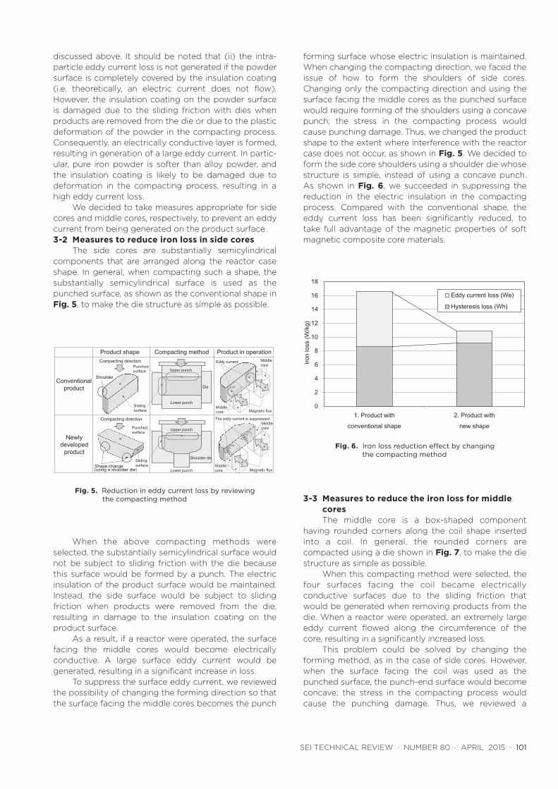
The side cores are substantially semicylindrical components that are arranged along the reactor case shape. In general, when compacting such a shape, the substantially semicylindrical surface is used as the punched surface, as shown as the conventional shape in Fig. 5, to make the die structure as simple as possible.
When the above compacting methods were selected, the substantially semicylindrical surface would not be subject to sliding friction with the die because this surface would be formed by a punch. The electric insulation of the product surface would be maintained. Instead, the side surface would be subject to sliding friction when products were removed from the die, resulting in damage to the insulation coating on the product surface.
As a result, if a reactor were operated, the surface facing the middle cores would become electrically conductive. A large surface eddy current would be generated, resulting in a significant increase in loss.
To suppress the surface eddy current, we reviewed the possibility of changing the forming direction so that the surface facing the middle cores becomes the punch
forming surface whose electric insulation is maintained. When changing the compacting direction, we faced the issue of how to form the shoulders of side cores. Changing only the compacting direction and using the surface facing the middle cores as the punched surface would require forming of the shoulders using a concave punch; the stress in the compacting process would cause punching damage. Thus, we changed the product shape to the extent where interference with the reactor case does not occur, as shown in Fig. 5. We decided to form the side core shoulders using a shoulder die whose structure is simple, instead of using a concave punch. As shown in Fig. 6, we succeeded in suppressing the reduction in the electric insulation in the compacting process. Compared with the conventional shape, the eddy current loss has been significantly reduced, to take full advantage of the magnetic properties of soft magnetic composite core materials.
3-3 Measures to reduce the iron loss for middle coresThe middle core is a box-shaped component
having rounded corners along the coil shape inserted into a coil. In general, the rounded corners are compacted using a die shown in Fig. 7, to make the die structure as simple as possible.
When this compacting method were selected, the four surfaces facing the coil became electrically conductive surfaces due to the sliding friction that would be generated when removing products from the die. When a reactor were operated, an extremely large eddy current flowed along the circumference of the core, resulting in a significantly increased loss.
This problem could be solved by changing the forming method, as in the case of side cores. However, when the surface facing the coil was used as the punched surface, the punch-end surface would become concave; the stress in the compacting process would cause the punching damage. Thus, we reviewed a
う
Product shape Compacting method Product in operation
Conventional product
Newly developed
product
Compacting direction
Compacting direction
Middle core
Middlecore
Lower punch
Upper punch
Die
Lower punch
Upper punch
Shoulder die
Punchedsurface
Sliding surface
Punched surface
Sliding surface
Eddy current
The eddy current is suppressed
Shoulder
Magnetic flux
Shape change(using a shoulder die)
Middle core
Middlecore
Magnetic flux
Fig. 5. Reduction in eddy current loss by reviewing the compacting method
0
2
4
6
8
10
12
14
16
18
1. Product withconventional shape
2. Product withnew shape
Iron
loss
(W/k
g)Eddy current loss (We)
Hysteresis loss (Wh)
Fig. 6. Iron loss reduction effect by changing the compacting method
102 · Pure Iron Based Soft Magnetic Composite Core That Enables Downsizing Automotive Reactors
method to remove and modify the electrically conduc-tive layer generated in the forming process.
Figure 8 shows the outline of the laser processing process. A slit-shaped laser beam is irradiated on the sliding surface of middle cores to melt and oxidize part of the electrically conductive layer, thereby blocking a potentially large eddy current along the sliding surface of the middle cores.
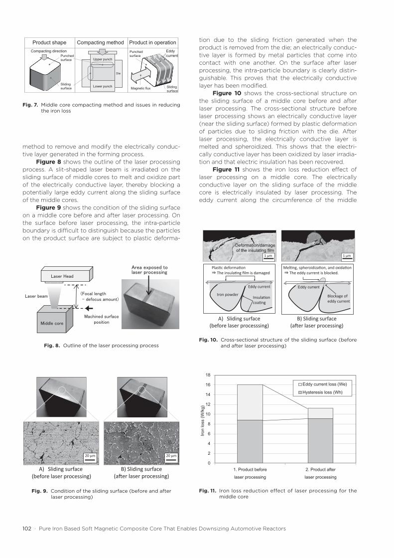
Figure 9 shows the condition of the sliding surface on a middle core before and after laser processing. On the surface before laser processing, the intra-particle boundary is difficult to distinguish because the particles on the product surface are subject to plastic deforma-
tion due to the sliding friction generated when the product is removed from the die; an electrically conduc-tive layer is formed by metal particles that come into contact with one another. On the surface after laser processing, the intra-particle boundary is clearly distin-guishable. This proves that the electrically conductive layer has been modified.
Figure 10 shows the cross-sectional structure on the sliding surface of a middle core before and after laser processing. The cross-sectional structure before laser processing shows an electrically conductive layer (near the sliding surface) formed by plastic deformation of particles due to sliding friction with the die. After laser processing, the electrically conductive layer is melted and spheroidized. This shows that the electri-cally conductive layer has been oxidized by laser irradia-tion and that electric insulation has been recovered.
Figure 11 shows the iron loss reduction effect of laser processing on a middle core. The electrically conductive layer on the sliding surface of the middle core is electrically insulated by laser processing. The eddy current along the circumference of the middle
Compacting directionPunchedsurface
Sliding surface
Product shape Product in operation
う
Eddy current
Compacting method
Lower punch
Upper punch
Die
Sliding surface
Punchedsurface
Magnetic flux
Area exposed tolaser processing
Middle core
Laser beam
Machined surfaceposition
(Focal length - defocus amount)
Laser Head
Fig. 7. Middle core compacting method and issues in reducing the iron loss
Fig. 8. Outline of the laser processing process
A) Sliding surface(before laser processing)
B) Sliding surface (after laser processing)
20 μm20 μm
Fig. 9. Condition of the sliding surface (before and after laser processing)
1 μm
Deformation/damage of the insulating film
Eddy current
1 μm
A) Sliding surface (before laser processsing)
B) Sliding surface (after laser processing)
Plastic deformation ⇒ The insulating film is damaged
Melting, spheroidization, and oxidation⇒ The eddy current is blocked.
Iron powder
Eddy current
Insulationcoating
Blockage of eddy current
0
2
4
6
8
10
12
14
16
18
1. Product beforelaser processing
2. Product afterlaser processing
Iron
loss
(W/k
g)
Eddy current loss (We)
Hysteresis loss (Wh)
Fig. 10. Cross-sectional structure of the sliding surface (before and after laser processing)
Fig. 11. Iron loss reduction effect of laser processing for the middle core
SEI TECHNICAL REVIEW · NUMBER 80 · APRIL 2015 · 103
core is blocked, leading to significant reduction in the eddy current loss. This simple process does not require any consumable auxiliary materials. Also, this environ-mentally friendly process does not generate industrial waste. We succeeded in taking full advantage of the magnetic properties of soft magnetic composite core materials while minimizing the processing cost.
4. Conclusion
We selected pure iron powder from among iron-based soft magnetic powders because it has high magnetic flux density, is advantageous for reducing the size of products, and is highly economical. We opti-mized the powder particle diameter, reviewed the product shape that can take full advantage of soft magnetic composite core properties while achieving shape flexibility derived from the powder metallurgy process, and developed a surface modification method by laser processing. Thus, we succeeded in effectively compacting the powder for automotive reactor cores. The size and weight of the new reactors have been reduced by about 10% compared with conventional reactors using electromagnetic steel sheet cores, while achieving the same performance.
References( 1 ) Y. Shimada, et al., SEI Technical Review, No. 162, 50 (2003)(2) T. Maeda, et al., SEI Technical Review, No. 166, 1 (2005)(3) S. Yamamoto, et al., SEI Technical Review, No. 185, 29 (2014)(4) Institute of Electrical Engineers of Japan, Magnetics Tech-
nology Committee (ed.): Magnetic Engineering Fundamen-tals and Applications, 46 (1999)
Contributors (The lead author is indicated by an asterisk (*).)
N. IGARASHI*• Senior Engineer, Sumitomo Electric
Sintered Alloy, LTD.
M. UOZUMI• Assistant Manager, Sumitomo Electric
Sintered Alloy, LTD.
T. KOSUGE• General Manager, Sumitomo Electric
Sintered Alloy, LTD.
A. SATO• Assistant General Manager, Advanced
Automotive Systems R & D Center
K. KUSAWAKE• Assistant Manager, Advanced Automotive
Systems R & D Center
K. YAMAGUCHI• Doctor of Engineering, Senior Assistant Manager, Analysis Technology
Research Center, R&D Laboratories
![International Journal of Pure and Applied Mathematics ... · Maninder Singh, et al [6] fabricated composite using aluminium 6061 and silicon oxide/titanium oxide . The composites](https://img.pdfslide.net/doc/110x75/5f2b2f19dae95347e0453aa6/international-journal-of-pure-and-applied-mathematics-maninder-singh-et-al.jpg)