Embed Size (px)
Citation preview

LANL-ER-SOP-06.01, RO Page 1 of 7
PURGING OF WELLS FOR REPRESENTATIVE SAMPLING OF GROUNDWATER
1.0 PURPOSE
This procedure describes methods for evacuating stagnant water from a well bore in sufficient quantities so that water samples collected are representative of the formation interval open to the well bore.
2.0 SCOPE
2.1 Applicability
This procedure for the purging of wells is applicable to field team members responsible· for collecting groundwater samples for the Environmental Restoration program.
2.2 Training
The field team members are responsible for obtaining representative water samples for analysis. The field team members must document that this procedure has been read and understood along with all of the procedures in Section 1.0, General Instructions.
3.0 DEFINITIONS
A. Hydrogen-Jon acilvity (pH): The effective concentration {activity) of dissociated nydrogen ions [H+] determines the acidity of an aqueous solution.
B. Redox-potential {Eh): Chemical reactions whereby a participating element changes its valence state, losing or gaining orbital electrons. This may be referred to as oxidationreduction potential.
C. Specific (Electrical) conductance: A measure of the ease with which a conduction current flows through a substance under the influence of an applied electric field. The conductance measurement provides an indication of ion concentration.
4.0 BACKGROUND AND/OR CAUTIONS
Groundwater that remains In the well bore is subject to chemical reactiQns over time that may significantly alter the composition of the formation water that initially entered the borehole. This water will not be representative of the water in the formation.
Upon exposure to atmospheric pressure and atmospheric oxygen content, the well water oxidation-reduction potential (Eh) and hydrogen-ion activity (pH) are subject to change. Reactions with the casing material may also affect water composition. Solubility may increase, dissolving constituents that under normal conditions would remain in the formation; or solubility
1111111111111111111111111111111 1111 12298

/ '
LANL-ER-SOP-06.01, RO Page 2 of 7
may decrease, precipitating constituents that under normal conditions would migrate through the aquifer in solution.
Ideally, a well should be purged until the water temperature, specific conductivity, and pH stabilize, where it is possible to collect groundwater samples representative of the formation water. However, the well may be purged dry before this state is reached. Samples collected after the well has been purged can then be sent to a laboratory for analysis.
The choice of equipment for well evacuation depends on the well yield, depth to water, casing diameter, the constituents to be analyzed for, and the requirements in the Site Work Plan and Sampling and Analysis Plan.
The decision to use any well evacuation system, whether list:~ below or not, should be based on what is best for that particular situation. Descriptions of a few well-evacuation systems, their advantages, and their limitations follow:
4.1 Bailer
With a stainless steel or TeflonTM bailer, water is removed from the well bore by a vessel of known volume. The vessel fills with water, and the unit is retrieved with a line or rope. The bailer purges the well's entire water column by removing standing water at the groundwater surface. Recharge is pulled into the well from the screened interval below.
For shallow, small-diameter wells with low yields, evacuation of the well by bailer is recommended. 'Bailers' 'are mechanically simple, lightweight and highly portable, constructed in many sizes, and require no external power source. Bailers are easily operated and cleaned and are inexpensive. In additiion, considerable time and cost savings are possible by using dedicated equipment to reduce the decontamination task and to limit the possibility of cross-contamination (EPA 1991) The primary limitation of bailers is their limited-volume purging capability, especially in deep wells where purging is labor intensive and time consuming. Bailers may also disturb the water by the pressure changes created by purging. Another disadvantage is that sampling personnel are directly exposed to any contaminants present.
4.2 Reciprocating Piston Submersible Pump
The pump assembly is suspended from the discharge tubing and submerged in the well. Water is transported through the discharge tube to the surface by piston action. A portable air compressor is used to drive the pump.
The reciprocating piston submersible pump is a portable system that can purge wells with water depths up to 500 ft. These pumps develop high pumping rates and can be operated in 2-inch-diameter wells. The pump is self-priming, and the compressed gas (air or nitrogen) that drives the pump does not contact the purged water. The pump is constructed from stainless steel or Teflonnc and can be decontaminated easily.

4.3 Electric Submersible Pump
LANL-ER-SOP-06.01, RO Page 3 of 7
The pump assembly is suspended from the discharge tubing and submerged in the well. The turbine in the pump bowl creates sufficient pressure to force water up the discharge pipe. Usually, a portable generator is required for power to the electric pump (unless electricity is available) and a truck-mounted winch may be required to move and lower the pump into the well.
The submersible pump may be used for purging both shallow, small-diameter wells and deep, large-diameter wells requiring large rates of discharge. Manufacturers offer small diameter stainless steel and Teflon'I'M constructed pumps capable of efficient purging at significant depths. The pump may be portable and self-contained.
Disadvantages of the submersible pump are ( 1 ) the pump can be difficult to decontaminate and transport along with auxiliary equipment; (2) the pump motor may be damaged by dry pumping, and the gears may be damaged by water containing high levels of suspended sediment; (3) large-capacity pumps are expensive; and (4) with negative displacement, pumps can significantly aerate the sample, thus changing the in situ chemistry and stripping low molecular weight volatiles. Careful monitoring during operation is needed to obtain optimum pump performance and to preclude the possibility of equipment damage.
Site workers preparing for field operations should read and understand the procedures outlined in LANL-ER-SOPs 2.0. Health and Safety in the Field. In addition, site workers should refer to site-specific Operable Unit Health and Safety plans for the particular health and safety equipment to be used.
5.0 EQUIPMENT
Equipment required for this procedure is listed in Attachment A.
6.0 PROCEDURE
The following procedure for purging a well is applicable regardless of which pump has been selected to best meet the constraints of the job. Procedural variations or additions specific to the type of pump used directly follow the general instructions.
A. Make provisions for proper storage and disposal of the extracted well water, as described in SOP-01.06, Management of AFt-General Wastes, and coordinate sampling effort with the Sample Coordination Facility.
B. Assemble the equipment and supplies listed in Attachment A.
•·
LANL-ER-SOP-06.01, RO Page4ot7
C. Verify that the equipment and meters are in good working order (obtain and review the manufacturer's operations, calibration, and instructions for the pH and conductivity meters to be used.) Record all calibration information on the Daily Activity Log in SOP-01.04.
D. In the field, locate the monitor wells to be sampled, and the appropriate staging and decontamination areas. If the amount of contamination differs significantly between wells, plan to purge and sample the least contaminated wells first.
E. Secure the work zone. Preclude passerby traffic through the work zone with barriers or cones. Place new plastic sheeting on the ground around the well in case something is dropped or must be placed on the ground.
F. Decontaminate the equipment that will con:3 in contact with the sample water before sampling the first well, and between samples, in accordance with SOP-02.07, General Equipment Decontamination. It is preferable that new rope be used for bailers.
G. Measure and record the depth to water in the well, if possible, from the reference point established for that well, in accordance with SOP-07.02, Fluid Level Measurement.
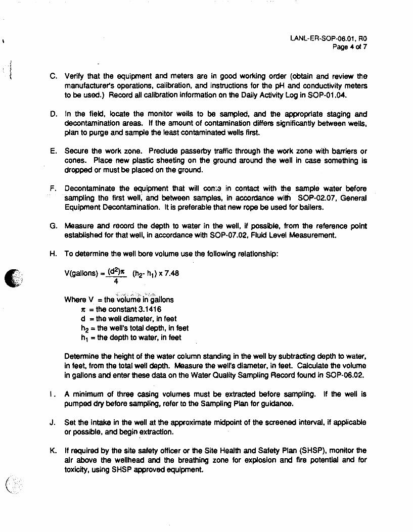
H. To determine the well bore volume use the following relationship:
V(gallons) = (d2)x (h2- h1) x 7.48 4
Where V = the volurru:! in gallons 1t = the constant 3.1416 d =the well diameter, in feet h2 =the well's total depth, in feet h1 =the depth to water, in feet
Determine the height of the water column standing in the well by subtracting depth to water, in feet, from the total well depth. Measure the weirs diameter, in feet. Calculate the volume in gallons and enter these data on the Water Quality Sampling Record found in SOP-06.02.
I . A minimum of three casing volumes must be extracted before sampling. If the well is pumped dry before sampling, refer to the Sampling Plan for guidance.
J. Set the intake in the well at the approximate midpoint of the screened interval, if applicable or possible, and begin extraction.
K. If required by the site safety officer or the Site Health and Safety Plan (SHSP), monitor the air above the wellhead and the breathing zone for explosion and fire potential and for toxicity, using SHSP approved equipment.

LANL-EA-SOP-06.01, RO Page 5 of 7
L. Record the discharge rate (usually by calibrated bucket and stopwatch) and the time periodically, and calculate and tabulate the gallons discharged since the start of pumping. Also measure and record the temperature and specific conductance of the well fluid, as described in SOP-06.02, Field Analytical Measurements on Groundwater Samples.
M. When the temperature and specific conductance have begun to stabilize, also begin to monitor the pH. If a flow-through cell is used, all pH readings should be made while the groundwater flow through the cell is halted, to eliminate streaming potentials.
N. When a minimum of three times the casing volume of fluid has been extracted, and field pH, specific conductance, and temperature have stabilized, the well is ready to sample. If these parameters do not stabilize, refer to the Site-Specific Work Plan and Sampling Plan for guidance.
0. Record the final, stable readings of pH, specific conductance, and temperature on the field parameter section of the form.
P. After shutting down the pump, measure and record the water-level drawdown in the well. These data may provide limited information about saturated zone hydraulics.
a. When sampling is completed, or at the end of the day, carefully clean the outside of the meters with a damp disposable towel to remove any visible dirt. Return them to a secure area and check the battery charge.
A. Decontaminate the pump assembly and other pieces of equipment that contacted the well fluid in accordance with SOP-02.07.
S. Restore the site to its original presampled condition.
T. Store the extracted groundwater as directed in the Site Work Plan and Sampling and Analysis Plan until its composition and proper disposal can be determined.
7.0 REFERENCES
The following procedures are directly associated with this procedure and should be reviewed before field operations:
LANL-ER-SOPs in Section 1.0, General Instructions. LANL-ER-SOPs in Section 2.0, Health and Safety in the Field. L.ANL-ER-SOP-06.02, Field Analytical Measurements of Groundwater Samples. l.ANL-ER-SOP-07.02, Fluid Level Measurement
Barcelona, M. J., J. P. Gibb, J. A. Helfrich, and E. E. Garske. 1985. •Practical Guide to Groundwater Sampling: U.S. Environmental Protection Agency report EPA/600/2-85/1 04. U.S. (,· Government Printing Office, Washington, D.C. ~
I

•' '
'
LANL-ER-SOP-06.01, RO Page 6 of 7
EPA, 1986. "ACRA Ground Water Monitoring Technical Enforcement Guidance Document" OSWER, Washington, D.C.
EPA, Region IV, 1991. "Environmental Compliance Branch Standard Operating Procedures and Quality Assurance Manual." Environmental Services Division, Athens, GA.
Korte, N., and P. Kearl. 1984. "Procedures for the Collection and Preservation of Groundwater and Surface Water Samples and for the Installation of Monitoring Wells." U.S. Department of Energy, Grand Junction, CO.
Morrison, A.D. 1983. "Groundwater ·Monitoring Technology, Procedures, Equipment and Applications.• TIMCO Manufacturing, I.':'C., 85-90, Evanston, IL
8.0 RECORDS
The following records are generated as a result of this procedure:
A. Daily Activity Logs which may include the following:
• •
• • •
Instrumentation and calibration information Order of sampling of the wells, and any comments regarding relative levels of contaminants Determination of casing volumes Health and safety monitoring Well discharge rate .
B. Water Quality Sampling Record, as appropriate
C. Water Quality Stabilization Record, as appropriate
D. Fluid Level Measurement Record, as appropriate
E. Completed Chain-of-Custody/Request for Analysis Form.
9.0 ATTACHMENT
A. Equipment and Supplies Checklist for Purging of Wells for Representative Sampling of Groundwater

ATTACHMENT A LANL-ER-SOP-06.01, RO
Page 7 of 7
EQUIPMENT AND SUPPLIES CHECKLIST FOR PURGING OF WELLS FOR REPRESENTATIVE SAMPLING OF GROUNDWATER
Purging pump or bailer
Water level measurement device
Calculator
Thermometer
Conductivity meter (and extra cup)
pH meter (and extra probe)
Air compressor or bottled nitrogen (as needed)
Standard reference solutions for calibrating specific conductance and pH meters
Portable generator, if needed
55-gallon drums or other water storage containers
Flow measuring equipment
Daily Activity Log
Water Quality Sampling Record forms
Water Quality Stabilization Record forms
Fluid Level Measurement Record forms
Chain-of-Custody/Request for Analysis forms
Sample Collection Logs
Variance Log
Custody Seals
Unique Sample Stickers
Sample Labels

(
Los Alamos National Laboratory
Environmental Restoration Program No: LANL-ER-SOP-06.02 Rev: 0
Standard Operating Procedure
Field Analytical Measurements of
Groundwater Samples
~~:j~nx by: rz r l-L c e C.-~ { ( (\_ t"\-~ ~_/ j cr_tlk'~l~ cr !? (] 11 ( (Print Name) (Date)
Technical ~b •f• tfe;; ~ Review by: I l,i"CVfA.( '-"
(Print Na e)
QPPL Approval:
PM Approval:
L a .,.,,, W\ c. q.H-e ~ (Print Narrti) ~M~ SlQnatUre
/fUvv~ (Signature)
Effective Date: 3 · \ ~ ·'\ ~
Jo/1/ &,/ (Date)
1 t> /J 'f /9 I (Ddte) •
to/t'-1/rt (Daf'e) I

'I
LANL-ER-SOP-06.02, RO Page 1 of 16 ( _
\
TABLE OF CONTENTS
1.0 PURPOSE ............................................... 2 2.0 SCOPE ............................................... 2
2.1 Applicability ............................................ 2 2.2 Training. . . . . . . . . . . . . . . . . . . . . . . . . . . . . . . . . . . . . . . . . . . . . .2
3.0 DEFINITIONS. . . . . . . . . . . ................................... 2 4.0 BACKGROUND AND/OR CAUTIONS ............................... 3 5.0 EQUIPMENT .............................................. 3 6.0 PROCEDURE .............................................. 3
6.1 Field Parameter Measurement ................................ 3 6.1.1 Temperature ....................................... 4 6.1.2 Specific (Electrical) Conductance. . . . . . . . . . . . . . . . . . . . . . . . . . . 4 6.1.3 pH ............................................. 4 6.1.4 Dissolved Oxygen .................................... 5 6.1.5 Turbidity ......................................... 5
6.2 Documentation ......................................... 5 6.3 Postoperation Activities. .................................... 5 •:
'
,;
7.0 REFERENCES ............................................. 6 8.0 RECORDS .... , :: .......................................... 7
9.0 ATTACHMENTS ............................................ 7 A. Equipment and Supplies Checklist. . . . . . . . . . . . . . . . . . . . . . . . . . . . . . 8 B. Water Quality Sampling Record. . . . . . . . . . . . . . . . . . . . . . . . . . . . . . . . 9 C. Water Quality Stabilization Record. . . . . . . . . . . . . . . . . . . . . . . . . . . . . 11 D. Data Form Completion .................................... 12
(
LANL-EA-SOP-06.02, RO Page 2 of 16
FIELD ANALYTICAL MEASUREMENTS OF GROUNDWATER SAMPLES
1.0 PURPOSE
This procedure desaibes acceptable methods for obtaining field measurements of the temperature, specific conductance, pH, alkalinity, turbidity, and dissolved oxygen of groundwater that closely represent the conditions that exist in the aquifer for the Environmental Restoration (ER) program.
2.0 SCOPE
2.1 Applicability
This procedure is applicable for field analytical measurements on groundwater samples for the ER program.
2.2 Training
The field team leader is responsible for ensuring that field team members collecting samples are practiced in the operation and calibration of the field analytical equipment. In addition all field team members using this procedure must document that they have read and understand this procedure, and the procedures in Section 1.0, General Instructions.
3.0 DEFINITIONS
A. Alkalinity: Various soluble mineral salts found in natural water and arid soils having a pH greater than 7. In water analysis it represents the carbonates, lucarbonates, bicarbonates, hydroxides, and occasionally the horates, chlorates, silicates, and phosphates.
B. pH: A measure of the acidity or alkalinity of a solution, numerically equal to 7 for neutral solutions, increasing with alkalinity and decreasing as acidity increases. Originally stood for the words •potential of hydrogen.•
C. Specific conductance: A measure of the ease with which an applied electric field can flow through a material. It is the reciprocal of resistivity and is measured in micromhos per centimeter at 250C.
D. Dissolved oxygen: The amount of oxygen dissolved in water, in parts per million (ppm) by weight, or in milligrams per liter (mg/1).
E. Turbidity (nephelometric): A measure of the intensity of light scattered by sample particulates relative to a standard reference suspension.· The range of water turbidity is measured from 0 to 40 Nephelometric Turbidity Units (NTU). Five NTU is the sample acceptance criteria (EPA 1986).

4.0 BACKGROUND AND/OR CAUTIONS
LANL-ER-SOP-06.02, RO Page 3 of 16
Field analytical parameters are normally measured along with well purging and groundwater sampling activities. Measurements of temperature, turbidity, specific conductance, and pH, done in advance of sampling, are also used as the final indication that a well is purged of stagnant water. The alkalinity and dissolved oxygen of groundwater are highly dependent on the availability and partial pressures of carbon dioxide and oxygen in the underground environment. Preservation of samples selected for turbidity analyses is not practical. Because the value of these parameters begins to change with prolonged exposure to atmospheric conditions, well head measurements generally yield the most accurate representation of in situ values.
Some properties or constituents in groundwater begin to change within minutes to hours of sample collection. If dependable results are required to more accurately characterize the in situ chemical properties of groundwater, immediate analysis may be advisable. The development of sophisticated and reliable portable field equipment now makes the analysis for many unstable constituents or properties possible at the collection site.
Site workers preparing for field operations should read and understand the procedures outlined in LANL-ER-SOPs, Section 2.0, Health and Safety in the Field. In addition, site workers should refer to site-specific Operable Unit Health and Safety plans for the particular health and safety equipment to be used.
5.0 EQUIPMENT
Equipment to implement this procedure is listed in Attachment A.
6.0 PROCEDURE
A. For quality control, field determinations should be repeated, from the beginning, on the same samples that are selected for lab replicates. Samples to be replicated may be selected on the basis of sample availability, but generally constitute 10 to 20% of the samples collected (SOP-01.05, Field Quality Control Samples, and the Sampling and Analysis Plan for details).
6.1 Field Parameter Measurement
A. Review SOP-06.01 , Purging of Wells for Representative Sampling of Groundwater, SOP-01.04, Sample Control and Field Documentation, and SOP-o1.06, Management of RFI-Generated Waste.
B. Assemble the equipment and supplies listed in Attachment A and the manufacturer's operations manuals. c~ .. ·

I ,;,
LANL-ER-SOP-06.02, RO Page 4 of 16
C. Verify that the equipment/meters are in good working order. (Review the manufacturer's instruction manuals for operation and calibration of the instruments to be used in the field.)
D. Refer to the site-specific documentation to locate the wells to be sampled and the appropriate staging and decontamination areas. If the amount of known or suspected contamination differs significantly between wells, plan to sample the least contaminated first.
E. Coordinate all sampling efforts with the Sample Coordination Facility.
The remainder of this section contains individual ooscriptions of fi~lc:t_ analytical. methods for measuring temperature, specific conductance, pH, dissolved oxygen, and turbidity. Refer to the site-specific documents for details about the number, types, and locations of measurements to be made.
6.1.1 Temperature
A. Obtain an immersion thermometer or thermocouple.
B. Ascertain that the field instrument has been calibrated to within ± 1.o·c against a thermometer calibrated to National Institute of Standards and Technology. (The field instrument is compared to the reference thermometer at two different tem;>eratures that bracket the temperature range normally measured in the field. Calibration must be done at least annually, and whenever the instrument is suspected of misuse, damage, or erratic or erroneous readings.)
C. Read the temperature immediately upon stabilization, and record on the Water Quality Sampling Record (Attachment B).
6.1.2 Specific (Electrical) Conductance
A. Obtain a specific-conductance meter that is battery operated, equipped with temperature compensator, and reads directly in micromhos/cm at 25"C. This meter is recommended to save time in converting resistance values to specific conductance and to ensure that the value is read in the field. Record reading on the Water Quality Sampling Record.
B. For all meters, follow the instructions in the manufacturer's operations manual for use and calibration of the equipment.
6.1.3 pH
A. Obtain a pH meter to be used for field measurements and the appropriate operation manual.
LANL-ER-SOP-06.02, RO Page 5 of 16 ( .
B. Operate the meter in accordance with the manufacturer's instructions. For purposes of this procedure, record pH value to the nearest 0.02 unit, on the Water Quality Sampling Record.
6.1.4 Dissolved Oxygen
A. Dissolved oxygen may be measured by several methods (dissolved oxygen meter or colorimeter).
B. Follow instructions in the operation manual supplied with the instrument, and record the final value of dissolved oxygen concentration to the nearest 0.1 mg/1 on the Water Quality Sampling Record.
6.1.5 Turbidity
A. Obtain a turbidimeter (Hach Model 2100, 2100A or acceptable equivalents) capable of turbidity measurements (Nephelometric) in conformance with EPA's Method 180.1 (EPA 1983).
B. Operate the equipment in conformance with the manufacturer's instructions and EPA's Method 180.1.
-C. Record the results of turbidity testing in the •comments• sections of the Water
Quality Sampling Record and the Groundwater Stablization Record.
6.2 Documentation
A. Obtain a sufficient number of the appropriate ER program field record and instrument test forms (refer to Attachments B through E) to record all measurements. Also refer to SOP-Q6.13 and SOP-01.04.
B. Additional comments may be provided on the Daily Activity Log, refer to SOP-01.04.
C. Refer to Attachment F, Data Form Completion, for detailed documentation instructions for most forms.
6.3 Postoperation Activities
A. When the work is completed, or at the end of the day, carefully clean the outside of the sampling instruments with a damp disposable towel to remove any visible dirt. Clean and decontaminate equipment per SOP-02.07, and replenish supplies. (
~·-B. Restore the site to the presampling conditions and fill open sampling holes as
described in the site-specific documents.

LANL-ER-SOP-06.02, RO Page 6 ot 16
C. Prepare samples and transport according to SOP-01.04, Sample Control and Field Documentation.
D. Return equipment to the equipment manager. Report malfunction, performance deviations, or damage.
7.0 REFERENCES
The following procedures directly relate to this procedure and should be reviewed before field operations:
LANL-ER-SOPs in Section 1.0, General Instructions. LANL-ER-SOPs in Section 2.0, Health and Safety in the Field. LANL-ER-SOP-06.01, Purging of Wells for Representative Sampling of Groundwater. LANL-ER-SOP-06.13, Surface Water Sampling.
Bates, A. l. and J. J. Jackson. 1984. "Dictionary of Geological Terms; Third Edition prepared by the American Geological Institute, Alexandria, VA.
Driscol F., 1986. "Groundwater and Wells; Second Edition. Johnson Division, St. Paul, MN.
EPA. 1983. "Meihoc;js. fo~. Ghemical Analysis of Water and Wastes." U.S. Environmental Protection Agency document EPA/~00/4-79-020. U.S. Government Printing Office, Washington, D.C.
EPA. 1986. RCRA Ground Water Monitoring Technical Enforcement Guidance Document. OSWER, U.S. Government Printing Office, Washington, D.C.
Korte, N., and P. Kearl. 1984. "Procedures for the Collection and Preservation of Groundwater and Surface Water Samples and for the Installation of Monitoring Wells." DOE, Grand Junction, co.
U.S. Geological Survey. 1977. 11 Chapter 2 - "Groundwater" prepared January 1980 in National Handbook of Recommended Methods for Water Data Acquisition. Office of Water Data Coordination, U.S. Geological Survey, U.S. Government Printing Office: 1981-341-614/131, Washington, D.C.

8.0 RECORDS
A. Completed Water Quality Sampling Record
B. Completed Water Quality Stabilization Record
LANL-ER-SOP-06.02, RO Page 7 of 16
C. Completed Daily Activity Log which may include any additional comments or deviations from the procedure.
9.0 ATTACHMENTS
A. Equipment and Scpplies Checklist for Field Analytical Measurements of Groundwater Samples
B. Water Quality Sampling Record
C. Water Quality Stabilization Record
D. Data Form Completion
(
c ' .
(
••
, ..
( ...
\' ---~.,
ATTACHMENT A LANL-ER-SOP-06.02, AO
Page 8 of 16
EQUIPMENT AND SUPPLIES CHECKLIST FOR FIELD ANALYTICAL MEASUREMENTS OF GROUNDWATER SAMPLES
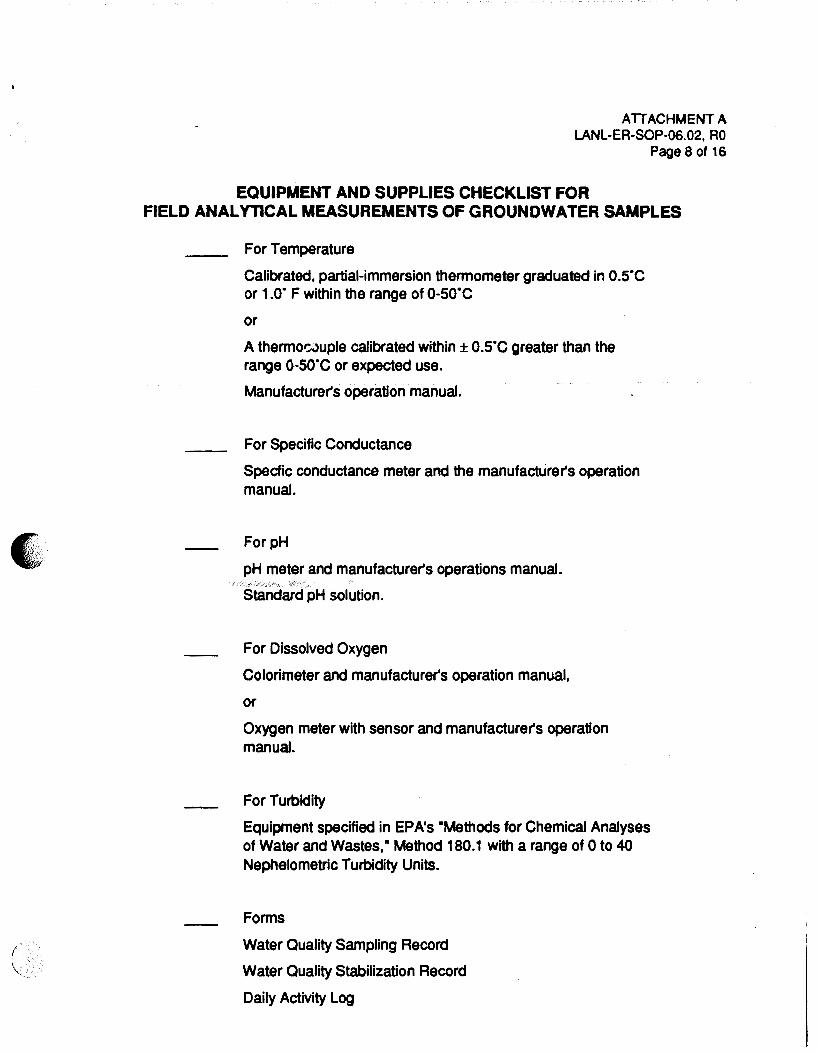
For Temperature
Calibrated, partial-immersion thermometer graduated in o.s·c or 1.0· F within the range of o-so·c or
A thermOt;JUple calibrated within ± o.s·c greater than the range o-so·c or expected use.
Manufacturer's operation manual.
For Specific Conductance
Specfic conductance meter and the manufacturer's operation manual .
For pH
pH meter and manufacturer's operations manual.
Standard pH solution.
For Dissolved Oxygen
Colorimeter and manufacturer's operation manual,
or
Oxygen meter with sensor and manufacturer's operation manual.
For Turbidity
Equipment specified in EPA's "Methods for Chemical Analyses of Water and Wastes," Method 180.1 with a range of 0 to 40 Nephelometric Turbidity Units.
Forms
Water Quality Sampling Record
Water Quality Stabilization Record
Daily Activity Log

ATTACHMENT A, Continued LANL-ER-SOP-06.02, RO
Page 9 of 16
EQUIPMENT AND SUPPLIES CHECKLIST FOR FIELD ANALYTICAL MEASUREMENTS OF GROUNDWATER SAMPLES
(Continued)
Chain-of-Custody/Request tor Analysis Forms
Sample Collection Logs
Custody Seals
Unique Sample Stickers
Sample Label~
( .. '
' .''

' '
ATTACHMENT B l.ANL-ER-SOP-06.02, AO
Page 10 of 16
WATER QUALITY SAMPLING RECORD
Date:------
LOS ALAMOS NATIONAL LABORATORY ENVIRONMENTAL RESTORATION
WATER QUALITY SAMPUNG RECORD Sheet __ of __
Technical Area---- Operable Unit-----
Site Work Plan:---------------..... :a~···l i···········iiifi"""········:
i LAif SAIIP\.1
L.~.~. Signature: ___ , _____________ _ :.,,ooooooouoooo•oooooooooooooooo;
Well Number: ----H..:~~-........... -__ Surf lot Control No.-------------
Complete _________ _
Date Sent----------
*Initial Groundwater Depth ___ _ ·sample Depth ___ _
PARAMETER MEASUREMENTS:
Potential of Hydrogen-ion Activity
Specific Concb;tance
Te~rature
Dissolved Oxygen
• Groundwater samples only
SAMPLE TYPES
D - Duplicate
F • Fteld
K-Known
T ·Trip
R • Replicate
A • Acid Blank
pH
Ec Tmp
DO
Q CHECK HERE IF CONnNUED ON BACK OF THIS SHEET
s.u. umhoSicm
·c mgtl
SAMPLING METHODS:
D - Deplh Integrated B ·Bailer C • Co"1)0site G ·Grab AL • Ail Lit San'4ller
BP • Bladder Pump PP - Peristaltic Pump SL • Suction lift Pump SP • Submersible Pump 0 . Other
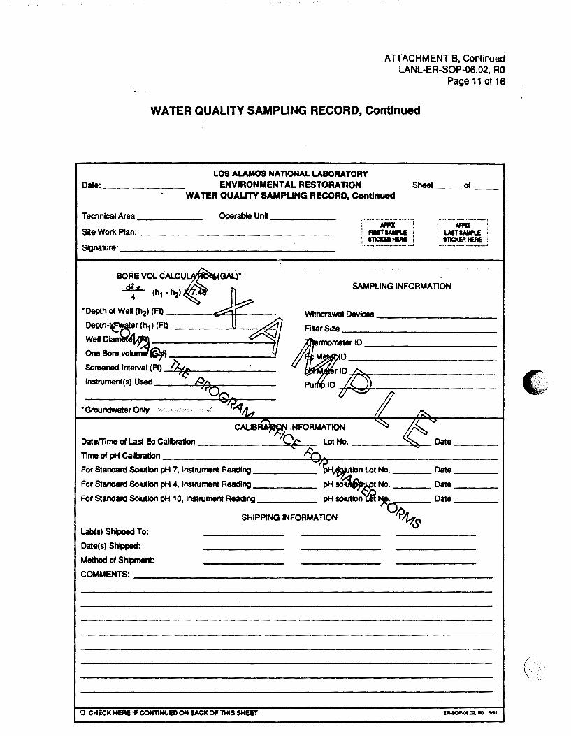
ATTACHMENT B, Continued LANL-ER-SOP-06.02, RO
Page 11 of 16
WATER QUALITY SAMPLING RECORD, Continued
LOS ALAMOS NATIONAL LABORATORY Date:------ ENVIRONMENTAL RESTORAnON Sheet __ of __
WATER QUAUTY SAMPUNG RECORD, Continued
Operable Unit-----Technical Area-----
Site Wort< Plan: ______________ _
SgMru~=---------------------
, .... ia~ ... ] : ................................. :
:·························---~
. AffiX . ; LAST SAIIILE ! ' STICIWIIEIIE f ~--······················-····_;
~OL CALCU~(GAL)" 4 (h1 • h:!> ~)jj
SAMPLING INFORMATION
• Depth of WeU (h:!) (Ft) ------E;;.o::;:++---
Depth-~~er (h1) (Ft)
Well Dia;:,w~--------~1 One Bore vo~~~ -:--------~ Screened Interval (Ft) _l'A_,_~711~e-------lnstrument(s) Used Af>Q
• Groundwater Only ~..q
Withdrawal Devices--------
Filter Size------------
~701D v ~r~-h;]:::==========~~-=--=--=--=--=-{/
.,..,..II"YN INFORMATION
Date/Time of Last Ec Calibratlon _______ ~_,Ct.E>€'......_- Lot No.----~~ Time of pH Cab'atlon t<'Q For Standard Solution pH 7, Instrument Reading ~~ion Lot No. ___ Date ___ _
For Standard So~lon pH 4, Instrument Reading pH so~.M No. Date ___ _
For Standard So~ion pH 10, Instrument Reading pH so~ion'Yii ~ Date ___ _
olr>ttts SHIPPING INFORMATION
Lab(s) Shipped To:
Date(s) Shipped:
Method of S~: COMMENTS: ____________________________ __
iJ CHECK HER& IF CONTINUED ON BACK OF THIS SHEET
(

I r
E •... ~
ATTACHMENT C LANL-ER-SOP-06.02, RO
Page 12 of 16
WATER QUALITY STABILIZAnON RECORD
LOS ALAMOS NATIONAL LABORATORY Date: ENVIRONMENTAL RESTORAnON Sheet __ of __
WATER QUAUTY STABIUZAT10N RECORD
Technical Area Operable Unit
Site Work Plan:
Signature:
TOTAL VOlU~~ TIME WITHDRAWN Ph Ec TEMP COMMENTS
(BcreV~ (umhoslcm) ("C)
{Gila) ~ P"' I ~
\.. tQA ~ ~'/ V/,. b 1 _jj
'-/ _b !It ~ 7~ A
c~ w ~ 7r'( ~- /~ /'>
~i ~ II -·· -· ·- ·.i.•.· ' ''£?- <K /A
\,.lt<';V,... .....,
/A '-~,.. ~
L !0 IJ..f..<J
'\,) /t:-1'1 I
,.('~
-'r'4?n >J
Q CHECK HERE IF CONTINUED ON BACK OF THIS SHEET E~-G1.02. R0 WI

DATA FORM COMPLETION
ATTACHMENT D LANL-ER-SOP-06.02, RO
Page 13 of 16
Use an indelible dark ink pen. Make an entry in each blank. For entry blanks for which no data are obtained, enter UNK for Unknown, NA for Not Applicable, or NO for Not Done. To change an entry, draw a single line through it, add the correct information above it, and date and initial the change. For all forms, complete the following information:
1. Technical Area (TA). Two-digit number indicating theTA in which the sampling is being done or sample is being studied.
2. Operable Unit. Four-digit number indicating the operable unit in which the sampling is being done or sample is being studied.
3. Sample Identification:
• If the Daily Activity Log addresses only one sample, attach a sticker from the batch of stickers that match the sticker number on the sample, and line through the box labeled MAttach Last Sample Number Here.M
• If the Daily Activity Log addresses a sequential number of samples, put the first matching sample sticker in the box marked •Firsr and put the last matching sample sticker in the box marked MLast. M
• If sample identifiers used are not sequential, be sure to amx the lowest sample sticker number in the left box, record the remaining sample identifiers: on the form ana Daily Activity Log, and line through the MLasr box.
4. Log Date and Time. The date and time when the measurement was made, in the following formats: DD-MMM-YY (e.g., 01-JAN-88) and the 24-hour clock time (e.g., 0837 for 8:37 a.m. and 1912 for 7:12p.m.).
5. Sheet Number. Number all the sheets that are used for this activity, by day or by some practical unit.
6. Weather and Other Comments. Record all other conditions pertinent to the sample collection in this section on the Daily Activity Log in SOP-01.04.
For the specific following forms, complete the additional information as indicated below.
WATER QUALITY SAMPLING RECORD
1. Lot Control Number. A two-digit number denoting that a given set of samples should be analyzed as a lot or group. (Normally, this number is not assigned by persons in the field ( · · collecting surface water samples.) \_

ATTACHMENT 0, Continued LANL-ER-SOP-06.02, AO
Page 14 of 16
2. Sample Type. A one-character code distinguishing the type of sample collected. This classification permits the analysis of data for specific groups of samples. The codes are identified on the form.
3. Sampling Method. A two-character code identifying the method used to collect a soil, rock. or water sample. The codes are identified on the form.
4. Well Number. Record number of well sampled.
5. Comments. Includes preservation method, acidified or nonacidified, type of acid (if acid was used to preserve water sample), and any additional information.
6. Parameter Measurements. The measurements listed below are recorded at the time the sample is collected.
a. Hydrogen-ion Activity--the pH units at the time of collection.
b. Specific Conductance--The specific conductance of the water sample in micro mhos/em in (~hos/cm) at 250C at the time of collection.
c. Temperature--The temperature of the water sample in degrees Celsius ("C) at the time of collection ...
d. Dissolved Oxygen--The dissolved oxygen content of the water sample in mg/1 at the time of collection.
7. Withdrawal Device. The sampling device used to collect the surface water sample.
8. Filter Size. Size of filter in use.
9. Thermometer I D. The identification of the thermometer used.
1 0. Conductivity Meter I D. The control number and manufacturer of the meter used to measure the specific conductance of samples or calibration solutions.
11. pH Meter ID. The control number and manufacturer of the meter used to measure the pH of the samples.
12. Pump ID. Identification of the pump in use.
13. Alkalinity Kit ID. Identification and model or serial number of the alkalinity kit used.
~ 14. Depth of well. Record depth in feet for groundwater sampling.

15. Depth to water. Record depth in feet for groundwater sampling.
ATTACHMENT 0, Continued LANL-ER-SOP-06.02, RO
Page 15 of 16
16. Well Diameter. Record diameter in feet for groundwater sampling.
17. One Bore Volume. Calculate volume in gallons using the equation on the form.
18. Screened Interval. Record in feet.
19. For a well, include information on the left side of the continuation page.
20. Instruments Used. The types of instruments used to obtain measurements, monitor air quality, or facilitate the cOllection of a sample or test performance.
21. Calibration Information. After performing the alkalinity titration test and immediately before sample collection, record the following information:
a. Datemme of Last Ec Calibration. Date and time that the specific conductivity meter was last calibrated.
b. Time of pH Calibration. Time the pH meter was calibrat~d.
c. Standard Solution pH Readings. The pH readings are to be recorded as the probe is immersed in standard solutions of pH 7.0, 4.0 and 10.0. Include expiration dates and lot numbers of the standard solutions.
22. Shipping Information. Information that includes the date, method, laboratory where the samples were shipped, and a comments section.
23. Comments. Add results of turbidity testing.
WATER QUALITY STABILIZATION RECORD (Attachment C)
This form contains data that are collected during well purging. These are described below.
1. Minimum purge volume. Total volume of well water to be extracted, at a minimum, is three to five well volumes before sampling may begin.
2. Time. The time when a field measurement of purged water was performed in the format HH:MM.
3. Total Volume Withdrawn. Using a bucket or flowmeter, the field sampler will note the number of gallons of water purged from the well at the time that a field measurement is taken. This entry is cumulative and represents the total volume of water purged before sampling may begin. A second column is provided so that the field sampler can equate
('
ATTACHMENT 0, Continued LANL-ER-SOP-06.02, RO
Page 16 of 16
gallons as bore volumes purged (see equation on page 2 of the Water Quality Sampling Record).
4. pH. The pH readings of water sampled during the purging process.
5. Ec. The specific conductance readings of water sampled during the purging process in J.UTlhOslcm.
6. Temp ("C). The temperature of the water sampled during the purging process.
7. Comments. Includes preservation method, acidified or nonacidified, type of acid (if acid was used to preserve water sample), and any additional information. Add results of turbidity testing.
Los Alamos National Laboratory
Environmental Restoration Program Standard Operating Procedure
No: LANL-ER-SOP-06.03
Sampling for Volatile Organics
Preparer: Sn.nd \-tl e_ . (l1 • J "'(lo r(Print Name)
Quality Review by:
Technical Review by:
QPPL Approval:
PM Approval:
Phil Fres~l{eL (Print Name)
/{cu-en L tuftf/J.!11 (Print Name)
~b~d/tl UvK~ (Print Name)
~JJ/Jv~,.,, (Signature)
j},/Jtvt/,J--(Signature)
Effective Date: 3 - ~ L, - '\ ~
Rev: 0
[0~~1 1/ (Da e)
3/3/9c:< (Date)
J, (-9 (Date)

SAMPLING FOR VOLATILE ORGANICS
LANL-ER-SOP-06.03, RO Page 1 of 7
1.0 PURPOSE
This procedure describes the collection of groundwater samples from wells for analysis of volatile organic compounds (VOCs), and the selection of equipment and materials to be used in this process.
2.0 SCOPE
2.1 Applicability
This procedure applies to all personnel responsible for obtaining VOC samples for the Environmental Restoration program.
2.2 Training
The field team leader and the field team member shall be familiar with the objectives of VOC sampling and must document that they have read and understand this procedure and the procedures in Section 1 .0, General Instructions.
3.0 DEFINITIONS
N/A
4.0 BACKGROUND AND/OR CAUTIONS
Sample retrieval systems potentially suitable for the valid collection of volatile organic samples are reciprocating piston-type submersible pumps; gear-driven submersible pumps; syringe samplers; and bailers (Barcelona 1984; Bennett 1988; Nielsen 1985; EPA 1986; EPA Region IV 1991 ). Field conditions and other considerations will limit the choice of system. The focus of concern must be to provide a valid sample for analysis, one that has been subjected to the least amount of turbulence and subsequent aeration possible. Sampling mechanisms capable of obtaining samples for VOC analyses are described below:
A. Reciprocating piston-type submersible pumps. These systems are portable, self-contained, and capable of delivery flow rates of 30 gallons per hour at lifts up to 500 feet. The pump fits into 2-inch wells, which is the most common monitor well diameter. The flow rate of the pump is varied by increasing or decreasing the driving pressure supplied to the pump from a compressed air container. The gas driving the pump does not contact the sample being purged.
B. Gear-driven submersible pumps. These pumps are not as complicated or as expensive as ( the bladder pumps. They provide comparable samples and are often easier to handle and

LANL-ER-SOP-06.03, RO Page 2 of 7
cleaner than other pumps. More care, however, must be exercised when sampling with them because the flow rate is not controllable and there is a greater potential for splashing and aeration of the sample.
C. Syringe samplers. Only a limited number of commercial, syringe-type samplers are available (two vendors are lEA and TIMCO). These devices are limited in sample volume and are specific to sampling for volatiles. Essentially, they operate with an evacuated chamber that is lowered down the well and allowed to fill from the pressure of the water. The entire mechanism is then brought to the surface with the sample. The sample can then be transferred to a sample vial, or the entire unit may be sent as the sample container, if preservation with chemical additives is not desired.
D. Bailers. The TeflonTM closed top, bottom charging type is the most appropriate bailer to collect water samples for volatile analysis. The bottom emptying device with a tap is also desirable. Several vendors provide acceptable designs. Generally, bailers can collect a representative sample, provided that the sampling personnel use extra care in the collection process.
Construction materials for pumps, bailers, and tubing are limited to stainless steel, Teflonn.t, and glass. The tendency of organics to leach into and out of many materials makes the selection of materials critical for these trace analyses. Plastics such as Tygon, for example, will be avoided. There are numerous ways of introducing foreign contaminants into a sample; these must be avoided by following strict sampling procedures and using only trained personnel.
Treatment of the sample with sodium thiosulfate preservative is required only when there is residual chlorine in the water. Residual chlorine could cause free radical chlorination and change the identity of the original contaminants.
If floating organics are of concern (as determined by field measurement for floating organics), a representative sample cannot be obtained with confidence.
The sensitivity of the analysis and the fragility of the samples require that all volatile samples are collected in duplicate.
Holding time for the analysis of volatiles is 7 days; vials for volatile organic analysis (VOA) may be kept for up to 14 days when preserved with acid. The samples will be shipped to the EM-9 Sample Coordination Facility (SCF) daily or following each completed sampling effort. The bottles must be shipped on their sides to aid in maintaining the airtight seal during shipment. Sample shippers (coolers) will be sealed with custody seals. They must also be adequately packed and cooled to ensure that they arrive intact. Refer to SOP-01.03, Handling, Packaging, and Shipping of Samples for further instructions.
5.0 EQUIPMENT
Equipment required to implement this procedure is listed in Attachment A.

6.0 PROCEDURE
LANL-ER-SOP-06.03, RO Page 3 of 7
A. Assemble the equipment and supplies listed in Attachment A. Ensure the proper operation of all sampling equipment. If any equipment requires calibration, be sure to record this information on the Daily Activity Log (SOP-01.04, Sample Control and Field Documentation).
B. Coordinate the sampling effort with the SCF. The SCF will give guidance regarding sample containers, preservation, and shipment to the SCF.
C. Locate monitor wells to be sampled and establish an appropriate decontamination area. Select the staging area and areas for managing purged water and expendable sampling materials. Provide barricades to public access or intrusion by non-essential personnel.
D. Decontaminate all sampling equipment before taking the first sample and between sampling intervals, in accordance with SOP-02.07, General Equipment Decontamination.
E. Purge wells before sampling, as specified in SOP-06.01, Purging of Wells for Representative Sampling of Ground Water. Ensure that the wells were not pumped dry and that flow was at rates too low to cause turbulence in the formation.
F. Perform other sampling tasks as specified in SOP-06.02, Field Analytical Measurements on Ground Water Samples before collecting volatile samples.
G. Determine if there is residual chlorine in the water to be sampled. If there is residual chlorine, treat the sample vials with a crystal of sodium thiosulfate before sample collection (SOP-01.02, Sample Containers and Preservation).
H. Determine contamination levels of wells. Monitor wells should be sampled from least to most contaminated to reduce the possibility for cross-contamination.
I. Collect VOC samples using the most appropriate sampling mechanism.
J. If a pump is used for sampling, follow the instructions for the specific pump. If a syringe is used, follow these steps:
1. If necessary, evacuate the syringe and lower the sampling device to just below the well screen.
2. Remove the constriction from the device and allow the syringe to fill with sample, applying slight suction.
3. Bring unit to the surface. If necessary, transfer the sample to vials. (

K. If a bailer is used, follow these guidelines:
LANL-ER-SOP-06.03, RO Page 4 of 7
1. Spread new plastic sheet on the ground around the wellhead, inside a secure, delineated zone, to establish a clean working area.
2. Decontaminate all sampling equipment per SOP-02.07.
3. Cool the bailer and sample containers before use to approximate the groundwater temperature. Avoid exposing them to direct sunlight.
4. Lower the TeflonTM closed top, bottom charging bailer into the water column slowly, noting the depth. Stop when the bailer reaches the well's screened interval.
5. Slowly recover the bailer; either retrieve the bailer, using a reel to collect the cable, or collect the cable in a cleaned stainless steel bucket.
6. Use the bailer's bottom discharge tube (TeflonTM) to fill the 40-ml vials by slow drainage.
7. Repeat step 5 as necessary to acquire sufficient sample quantities.
8. The vials (40-ml) should be competely fil~ed to prevent volatilization, and extreme caution should be exercised when filling a vial to avoid any turbulence which could also produce volatilization. The sample should be carefully poured down the side of the vial to minimize turbul.ence. As a rule, it is best to gently pour the last few drops into the vial so that surface tension holds the water in a "convex meniscus." The cap is then applied and some overflow is lost, but air space in the bottle is eliminated. After capping, turn the bottle over and tap it to check for bubbles. If any bubbles are present, repeat the procedure once. If a second try is required, use a new sample container. When collecting water samples for purgeable organic compounds, duplicate samples should always be collected from each location.
Water samples to be analyzed for purgeable organic compounds should be stored in 40-ml septum vials with screw cap and TeflonTM-silicone disk in the cap to prevent contamination of the sample by the cap. The disks should be placed in the caps (TeflonTM side to be in contact with the sample) by the sample container vendor before the beginning of the sampling program.
9. After each use, the sampling equipment must be decontaminated in accordance with SOP-02.07.
10. A sampling blank should be acquired periodically to test the decontamination procedure's efficiency.
11. A trip blank of distilled deionized water should be carried throughout the sampling, preservation, and shipping process.

6.1 Documentation
LANL-ER-SOP-06.03, RO Page 5 of 7
For each sample collected, initiate a Sample Collection Log, Chain-of-Custody/Request for Analysis form, and affix a Sample Label to the sample container. SOP-01.04, Sample Control and Documentation, contains copies of the forms and labels and instructions for completing them.
6.2 Postoperation Activities
A. If decontamination of sampling equipment is necessary, decontaminate as instructed in SOP-02.07, General Equipment Decontamination.
B. Make sure all wells are properly labeled and the location ID is readily visible on the protective casing. Make sure all samples are properly labeled.
C. Prepare samples and transport them to the SCF according to SOP-01.02, SOP-01.03, and SOP-01.04.
D. The field team leader will contact the SCF (EM-9) to ensure that samples arrived safely and instructions for sample analyses are clearly understood. Record this information on the Daily Activity Log.
7.0 REFERENCES
The following procedures are directly associated with this procedure and should be reviewed before packaging, labelling, and shipping samples:
LANL-ER-SOPs in Section 1.0, General Instructions. LANL-ER-SOP-02.07, General Equipment Decontamination. LANL-ER-SOP-06.01, Purging of Wells for Representative Sampling of Ground Water. LANL-ER-SOP-06.02, Field Analytical Measurements on Ground Water Samples.
Barcelona, M. J., J. A. Helfrich, E. E. Garske, and J.P. Gibb. 1984. "A Laboratory Evaluation of Groundwater Sampling Mechanisms." Groundwater Monitoring Review, Spring 1984: 32-41.
Barcelona, M. J., J. A. Helfrich, and E. E. Garske. 1985. "Sampling Tubing Effects on Groundwater Samples." Analy. Chern. 57:460-63.
Bennett, Robert Co. 1988. " Operation Manual for the Bennett Sampling Pump." Amarillo, TX.
DOE. 1985. "Field Technical Representative Manual." 2nd ed. U.S. Department of Energy, Uranium Mill Tailings Remedial Action Project Office, Albuquerque Operations Office document, June 1985. Albuquerque, NM. ( ,.

LANL-ER-SOP-06.03, RO Page 6 of 7
EPA. 1981. "Manual of Groundwater Quality Sampling Procedures." U.S. Environmental' Protection Agency report EPA-600/2-81-160. Washington, D.C.
EPA. 1982. "Handbook for Sampling and Sample Preservation of Water and Wastewater," U.S. Environmental Protection Agency report EPA-600/4-82-029. Washington, D.C.
EPA. 1985. "Practical Guide for Groundwater Sampling.: U.S. Environmental Protection Agency report EPA/600/2-85/1 04, September 1985. Washington, D.C.
EPA. 1986. "RCRA Ground Water Monitoring Technical Enforcement Guidance Document." OSWER, Washington, D.C.
EPA Region IV, 1991. "Environmental Complia:'lce Branch Standard Operating Procedures and Quality Assurance Manual Environmental Services Division." Athens, GA.
Nielsen, David M., and Gillian L. Yeates. 1985. "A Comparison of Sampling Mechanisms Available for Small-Diameter Groundwater Monitoring Wells." Groundwater Monitoring Review, Spring 1985: 83-99.
8.0 RECORDS
The following records are generated as a result of this procedure:
A. Completed DailY, Activity Log including any deviation or other pertinent information
B. Completed Chain-of-Custody/Request for Analysis Form
C. Completed Sample Collection Log including any deviation or other pertinent information.
9.0 ATTACHMENTS
A. Equipment and Supplies Checklist for Sampling Volatile Organics.
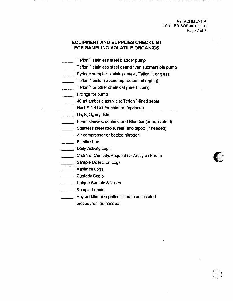
EQUIPMENT AND SUPPLIES CHECKLIST FOR SAMPLING VOLATILE ORGANICS
TeflonTM stainless steel bladder pump
ATTACHMENT A LANL-ER-SOP-06.03, RO
Page 7 of 7
TeflonTM stainless steel gear-driven submersible pump
Syringe sampler; stainless steel, TeflonTM, or glass
TeflonTM bailer (closed top, bottom charging)
TeflonTM or other chemically inert tubing
Fittings for pump
40-ml amber glass vials; TeflonTM-Iined septa
Hach® field kit for chlorine (optional)
Na2S20 4 crystals
Foam sleeves, coolers, and Blue Ice (or equivalent)
Stainless steel cable, reel, and tripod (if needed)
Air compressor or bottled nitrogen
Plastic sheet
Daily Activity Logs
Chain-of-Custody/Request for Analysis Forms
Sample Collection Logs
Variance Logs
Custody Seals
Unique Sample Stickers
Sample Labels
Any additional supplies listed in associated
procedures, as needed

Los Alamos National Laboratory
Environmental Restoration Program Standard Operating Procedure
No: LANL-ER-SOP-06.04 Rev: 0
Sampling Commercial/Municipal/Domestic Wells
Prepaoer:S~~ .(J1p-M S,~ f.~to-)6-q/ (Print Name) (Signature) (Date)
QuaiHy Review by:
Technical Review by:
QPPL Approval:
PM Approval:
r,1 G L l l ~ · .<'2 '"'~ /'J' 11 'bv\.,LCQ_ '!-0-- f!l. '--vv- /J~ .....--cJOI..-\..~._ 1/!o/7'; (Print Name) (Signature) (Date)
~;y~ ~~ !!_~~c ~ lfi fl!i ;t ft lb '9 v/~ I ~ntName) {~~L..:.-nat..L-ure-) ...L:--- (Date)T
Lr::j ((,/ (Print Name)
J?}J-wu;(;~ (Print Name)
Effective Date: 3 ... \ l..t • q)..
: .· / ... ; ... / ~.' /
(D-~e}. /
!fr/d-!J~ (Signature)
LANL-ER-SOP-06.04, RO Page 1 of 6
SAMPLING COMMERCIAUMUNICIPAUDOMESTIC WELLS
1.0 PURPOSE
This procedure describes methods for sampling commercial, municipal, and domestic water supply wells.
2.0 SCOPE
2.1 Applicability
This procedure is applicable to field team members involved in sampling commercial~. municipal, and domestic wells for the Environmental Restoration program.
2.2 Training
The field team leader and field team members should be familiar with the objectives of sampling commercial, municipal, and domestic wells and must document that they have read and understand this procedure and all of the procedures in Section 1.0, General Instructions.
3.0 DEFINITIONS
N/A
4.0 BACKGROUND AND/OR CAUTIONS
Water samples may be collected from industrial, public, and private water supply wells to support the site characterization of a facility (EPA 1986). Specific sampling protocols must be considered on an individual basis; each well may be completed into different aquifers, or parts of aquifers, will have a different pump, construction material, pipe, and access point for sample collection. The water samples collected are to be representative of the water aquifer within a given segment of the distribution system and potentially representative of the aquifer in which the well was installed. Consult the site-specific documentation for specific instructions for each well.
In most instances, details concerning installation and development of these wells will be incomplete. Because non-inert materials in the well and distribution . systems can alter the chemistry of the sample, it is important to collect the sample as close to the wellhead as possible (EPA Region IV 1991). Following property documented field procedures will ensure that privately owned wells do not become damaged or contaminated through sampling activities. Representative water samples must be taken from a discharge pipe or water faucet located near the supply well. Under no circumstances will the field technician pull a pump or insert a
I
(- .•. ·.· .•
-';...
' '
' '
~·
/.
/
LANL-ER-SOP-06.04, RO Page 2 of 6
sampling device directly into a well unless directed by or with documented approval from the field team leader and property owner.
Site workers preparing for field operations should read and understand the procedures outlined in LANL-ER-SOPs Section 2.0, Health and Safety in the Field. In addition, site workers should refer to site-specific Operable Unit Health and Safety plans for the particular health and safety equipment to be used.
5.0 EQUIPMENT
See Attachment A, Equipment and Supplies Checklist, for a list of equipment used in this procedure.
6.0 PROCEDURE
For collection of groundwater from public and private water supply wells, proceed as outlined below.
6. 1 Preliminary Activities
A. Assemble the equipment and supplies listed in Attachment A. Ensure the proper operation of all sampling equipment. If calibration is required, record calibration information on the Daily Activity Log in SOP-01.04.
B. Notify the analYtical.laooratory of sample types, the approximate number of samples, and the approximate arrival date. Coordinate all sampling efforts with the Sample Coordination Facility.
C. Contact the carrier that will transport samples to obtain information on regulations and specifications.
D. Contact the well owner and set up a time to collect water samples and perform field chemistry measurements. If possible, arrange for commercial, municipal, and domestic wells to be sampled before the monitor wells.
E. If possible, discuss your activity with the well owner and set up the sampling vehicle in a location that will not inconvenience area residents. Also, discuss with the well owner how the purge/wastewater can be disposed of in accordance with SOP-01.06, Management of RFI-Generated Waste.
F. Decontaminate all sampling equipment before taking the first sample and between sampling intervals in accordance with SOP-02.07, General Equipment Decontamination.
LANL-EA-SOP-06.04, RO Page 3 of 6
G. Select a discharge pipe or faucet closest to the well for sampling or direcUy from the ( well, if possible.
H. Determine if the discharge pipe or water faucet is on a water treatment system of some type (water softener, for example). Note this in the comments section of the Groundwater Quality Sampling Record (refer to SOP-06.02, Field Analytical Measurements on Groundwater Samples).
I. If possible, take a water level measurement as instructed in SOP-07 .02, Fluid Levef, Measurements. For Laboratory supply wells, record the airline pressure or transducer. readout.
J. If the well is documented, well completion data will have been recorded and can be obtained. Calculate the bor~ volume as described in SOP-06.01, Purging of Wells for Representative Sampling of Groundwater.
6.2 Sampling Procedures
A. Detach aerators, strainers, or sink hose attachments prior to sampling.
B. Connect the appropriate sampling apparatus (cleaned tubing, connectors, and Rowthrough bath) to the discharge pipe. Remember that the sample should be collected as close as possible to the source, and directly from the wellhead when feasible.
C. Set up and calibrate the equipment. Calibration information must be recorded on the Daily Activity Log.
D. Begin withdrawing water from the well. If possible, run the water tor at least 10 min to ensure that pipes have been thoroughly flushed. If this is not possible, purge the well as specified in SOP-06.01.
E. Perform field measurements according to SOP-06.02, Field Analytical Measurements on Groundwater Samples.
F. Collect water samples according to SOP-01.02, Sample Containers and Preservation. and SOP 06.03, Sampling for Volatile Organics.
6.3 Documentation
For each sample collected, initiate a custody record on the Chain-of-Custody/Request-forAnalysis forms and affix a Water Sample Identification Label to the sample container. SOP-01.04, Sample Control and Field Documentation, contains copies of the forms and labels and instructions for completing them. Supply well documentation must be entered on a Well Completion Information form, per SOP 05.01. (
I . . . j;
LANL-ER-SOP-06.04, RO Page4of 6
Whenever a well is purged or sampled, record all field measurements and chemistry determinations on either the Groundwater Level or the Groundwater Levels and Gasoline Thickness Data forms, as well as the Groundwater Quality Sampling Record form. Copies of these forms and instructions for completing them are provided in SOP-07.02, Fluid Level Measurement, and SOP-06.02, Field Analytical Measurements on Groundwater Samples, respectively.
6.4 Postoperation Activities
A. Make sure all survey or sampling locations are properly staked and the location ID is readily visible on the location stake.
B. Prepare samples and transport according to SOP-01.04 Sample Control and Field Documentation, SOP-01.02 Sample Containers and Preservation, and· SOP-Q1.03, Handling, Packaging, and Shipping of Samples.
C. Contact the analytical laboratory to ensure that samples arrived safely and instructions for sample analyses are clearly understood.
D. If decontamination of sample containers is necessary, decontaminate according to SOP-02.07.
7.0. REFERENCES
The following procedures>are directly associated with this procedure and should be reviewed before sampling commercial, municipal, and domestic wells:
LANL-ER-SOPs in Section 1.0, General Instructions. LANL-ER-SOPs in Section 2.0, Health and Safety in the Field LANL-ER-SOP-05.01, Monitor Well Construction. LANL-ER-SOP-06.01, Purging of Wells for Representative Sampling of Ground Water. LANL-ER-SOP-06.02, Field Analytical Measurements on Ground Water samples. LANL-ER-SOP-06.03, Sampling for Volatile Organics. LANL-ER-SOP-Q7.02, Fluid Level Measurement.
EPA, 1986. •RCRA Ground Water Monitoring Technical Enforcement Guidance Document• OSWER, Washington, D.C.
EPA Region IV, 1991. ·environmental Compliance Branch Standard Operating Procedures and Quality Assurance Manual Environmental Services Division. • Athens, GA.
8.0 RECORDS
Records generated as a result of this procedure are:
LANL-ER-SOP-06.04, RO Page 5 of 6
A. Completed Daily Activity Log that includes (if alternate forms are not available):
• Groundwater Level • Groundwater Quality Sampling Record • Deviations (if applicable) • Any other pertinent information.
B. Completed Chain-of-Custody/Request for Analysis Form
9.0 ATTACHMENTS
A. Equipment and Supplies Checklist for Sampling CommerciaVMunlcipaVOomestic Wells
(

• ' ' ,•
/
\
ATTACHMENT A LANL-ER-SOP-06.04, RO
Page 6of 6
EQUIPMENT AND SUPPLIES CHECKLIST FOR SAMPLING COMMERCIAL/MUNICIPAL/DOMESTIC WELLS
TeflonTM tubing
Pump fittings
Water level probe
Calibrated bucket
Stopwatch
Sample containers and preservatives
Foam sleeves, vermiculite coolers, and Blue Ice (or equivalent)
Plastic sheet
Daily Activity Log
Chain-of-Custody/Request-for-Analysis Forms
Sample Collection Log
Variance Log
Custody Seals
Unique Sample Stickers
Sample Labels
Any additional supplies listed in associated procedures, as needed

(
Los Alamos National Laboratory
Environmental Restoration Program
Standard Operating Procedure
No: LANL-ER-SOP-06.05
Soil Water Samples
Rev: 0
Preparer:Sc "'d H w, n l"X ~G. [V~/\ }0 -d~ -1 ) (Pnnt Name) ' (Signature) ' (Date)
Quality (j5 /' 11 () 1 Review by: ' V"U..C e l..)c'-'<XC<~\ .ey
(Print Name)
Technical -:fl · \ ke<'Q n" Review by:J\ I -~J U r · v (P nt N1im )
QPPL Approval:
PM Approval: R,t.twl/~ £t,d w~~ocJ~
(Print Name) (Signature)
Effective Date: 3 - l t.c ~ 9. "'d-
9/3o/1 1 (Date)
,o p vj?, (Date} I

TABLE OF CONTENTS
LANL-ER-SOP-06.05, RO Page 1 of 19
1.0 PURPOSE .............................................•.. 2 2.0 SCOPE. .................................................. 2
2.1 Applicability ............................................ 2 2.2 Training. . . . . . . . . . . . . . . . . . . . . . . . . . . . . . . . . . . . . . . . . . . . . .2
3.0 DEFINITIONS .............................................. 2 4.0 BACKGROUND AND/OR CAUTIONS ............................... 2 5.0 EQUIPMENT ...........................................•.. 3 6.0 PROCEDURE .............................................. 3
6.1 Assembly of Soil Water Sampler . . . . . . . . . . . . . . . . . . . . . . . . . . . . . . . 3 6.2 Installation of Soil Moisture (Water) Sampler. . . . . . . . . . . . . . . . . . . . . . . .4 6.3 Final Installation ......................................... 5 6.4 Collecting Soil Water Samples . . . . . . . . . . . . . . . . . . . . . . . . . . . . . . . . 6 6.5 Sample Filtering/Preservation. . . . . . . . . . . . . . . . . . . . . . . . . . . . . . . . . 7 6.6 Obtaining Field Measurements . . . . . . . . . . . . . . . . . . . . . . . . . . . . . . . . 8 6.7 Postoperation ......... _ ............................ _ ... 8
7.0 REFERENCES ............................................. 9 8.0 RECORDS ............................................... 9 9.0 ATIACHMENTS ............................................ 9
A. Equipment and Supplies Checklist. . . . . . . . . . . . . . . . . . . . . . . . . . . . . 11 B. Soil Watei'Sampling Field Data ............................... 12 C. Soil Water Sampler Installation Showing Bentonite Seal . . . . . . . . . . . . . . . . 13 D. Soil Water Sampler Installation Showing Pressure-Vacuum Assembly ........ 14 E. Purging of Slurry Water with Soil Water Sampler . . . . . . . . . . . . . . . . . . . . 15 F. Collection of Soil Water Samples. . . . . . . . . . . . . . . . . . . . . . . . . . . . . . 16 G. Soil Water Sampler Installation . . . . . . . . . . . . . . . . . . . . . . . . . . . . . . . 17 H. Data Form Completion .................................... 18

• . . . ·
SOIL WATER SAMPLES
1.0 PURPOSE
LANL-ER-SOP-06.05, RO Page 2 of 19
This procedure defines the equipment and proper method for sampling soil water.
2.0 SCOPE
2.1 Applicability
This procedure is applicable to the operation of soil water samplers (lysimeters) for the Environmental Restoration Program.
2.2 Training
The field team leader is responsible for monitoring the proper implementation of this procedure. Field team members using this procedure should be familiar with the objectives of the program, including sample collection, preservation and handling, and must document that they have read and understand this and the procedures in Section 1.0, General Instructions.
3.0 DEFINITIONS
A. Drilling string: The string of pipe that extends from the bit to the driving mechanism that serves to carry the mud down the borehole and to rotate the bit.
B. Split-spoon sampler: A hollow, tubular sampling device driven by a weight below the drill stem to retrieve soil samples.
C. Unsaturated hydraulic conductivity: A coefficient describing the rate at which a fluid can potentially move through a permeable, unsaturated medium (EPA 1986a}.
D. Vadose zone: The partially saturated zone between the surface and the water table.
4.0 BACKGROUND AND/OR CAUTIONS
Soil water samplers, or lysimeters, are used to sample water in the vadose zone. The lysimeter applies pressure to the vadose zone, which mobilizes pore water partially filling soil particle interstices. Once the water is mobilized it will move toward and will collect in the sampling vessel of the lysimeter. If present, contamination generally is mobilized along with the water and can be detected as constituents of the pore water.
Three common types of lysimeters are available: vacuum, pressure-vacuum, and high-pressurevacuum. Selection of the appropriate lysimeter is based on the target sampling depth. The vacuum lysimeter is designed to sample from 0 to 6 feet; the pressure-vacuum lysimeter is
LANL-ER-SOP-06.05, RO Page 3 of 19
designed to sample to 50 feet; and the high-pressure-vacuum lysimeter is designed to sample greater depths. Soil water samples may be obtained from shallow depths with a hand pump and from greater depths with pressurization by an inert gas such as nitrogen. Lysimeters can be installed singly or in clusters of one or more at varying depths. The site-specific work plan will define the types of lysimeters and the sampling locations and depths.
Lysimeters may be installed in a variety of subsurface environments and soil types. Lysimeters are most efficient in unconsolidated granular soils ranging in particle size from coarse sand to silt. Lysimeters may not perform efficiently in clay soils. Pore pressures in clay may be great enough to significantly reduce transport of soil water. This is a problem for two main reasons: (1) the volume of the sample may not be adequate for metals analysis, and (2) the time required to collect adequate volume for volatile organic analysis may exceed the holding time. Another limiting factor for lysimeters is that the sample vessel may become clogged by fine particles Jr the waste type may cause bacteria or a chemical precipitate to form.
A variety of drilling methods may be used to achieve the desired depth for lysimeter installation. However, drilling methods employing fluids should not be used. Borehole integrity must be maintained, and the drilling method should be chosen accordingly.
The sampling devices can be damaged as a result of intrusion by people, wildlife, livestock, or mechanical equipment. Fencing around the site may be necessary. Do not cover the surface area directly above the samplers in a way that interferes with the normal percolation of soil moisture down to the depth of the soil water sampler.
Site workers preparing for field operations should read and understand the procedures outlined in LANL-ER-SOPs, Section 2.0, Health and Safety in the Field. In addition, site workers should refer to site-specific Operable Unit Health c...1d Safety plans for the particular health and safety equipment to be used.
5.0 EQUIPMENT
Refer to the equipment list in Attachment A.
6.0 PROCEDURE
A. Assemble the equipment and supplies. Ensure the proper operation of all sampling equipment.
B. Coordinate all sampling efforts with the Sample Coordination Facility.
C. Lysimeters are generally packaged in protective plastic by the .manufacturer; therefore, a distilled water rinse is sufficient. (These procedures may vary according to manufacturer's specifications.) Harsh chemicals may damage the equipment.
•
c;
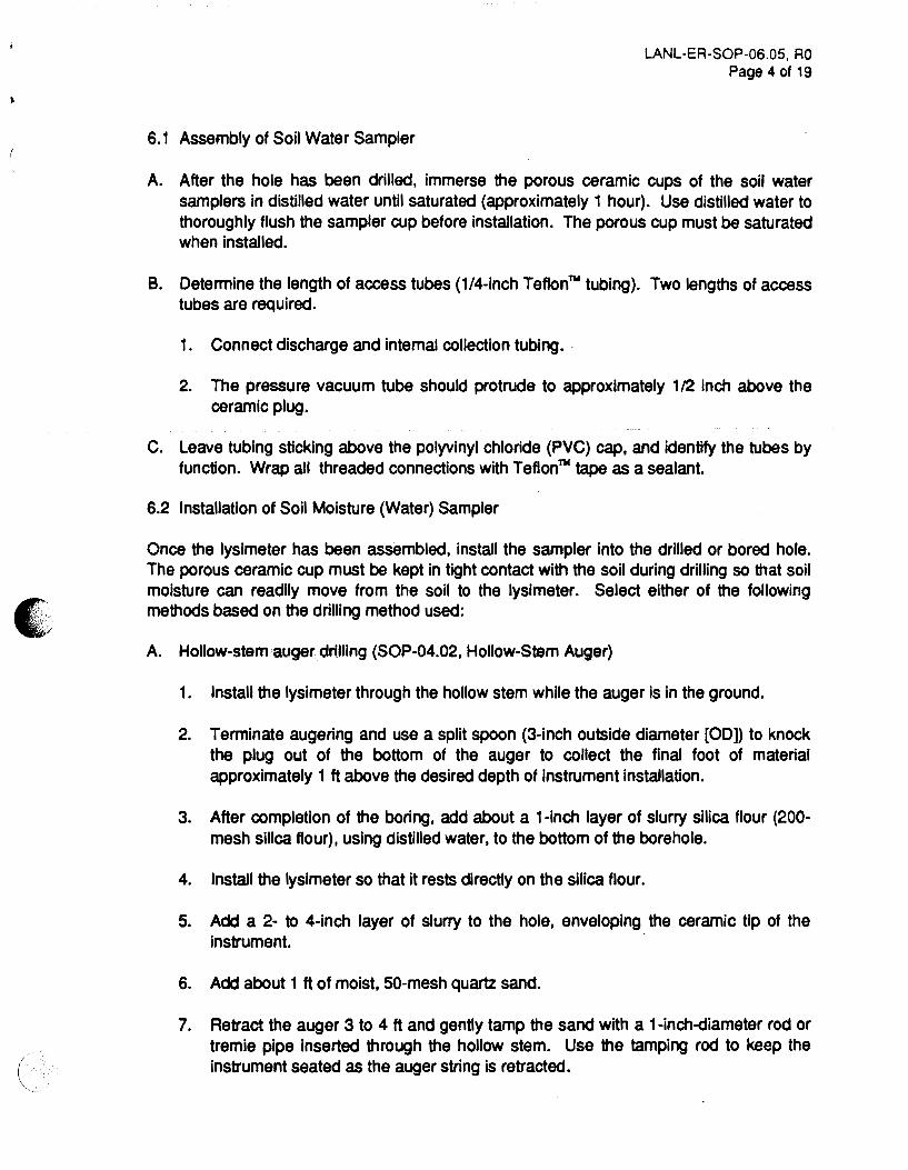
6. 1 Assembly of Soil Water Sampler
LANL-ER-SOP-06.05, RO Page 4 of 19
A. After the hole has been drilled, immerse the porous ceramic cups of the soil water samplers in distilled water until saturated (approximately 1 hour). Use distilled water to thoroughly flush the sampler cup before installation. The porous cup must be saturated when installed.
B. Determine the length of access tubes (1/4-inch Teflonn. tubing). Two lengths of access tubes are required.
1. Connect discharge and internal collection tubing ..
2. The pressure vacuum tube should protrude to approximately 1/2 inch above the ceramic plug.
C. Leave tubing sticking above the polyvinyl chloride (PVC) cap, and identify the tubes by function. Wrap all threaded connections with Teflonn. tape as a sealant.
6.2 Installation of Soil Moisture (Water) Sampler
Once the lysimeter has been assembled, install the sampler into the drilled or bored hole. The porous ceramic cup must be kept in tight contact with the soil during drilling so that soil moisture can readily move from the soil to the lysimeter. Select either of the following methods based on the drilling method used:
A. Hollow-stem auger drilling (SOP-04.02, Hollow-Stem Auger)
1. Install the lysimeter through the hollow stem while the auger is in the ground.
2. Terminate augering and use a split spoon (3-inch outside diameter [00)) to knock the plug out of the bottom of the auger to collect the final foot of material approximately 1 ft above the desired depth of instrument installation.
3. After completion of the boring, add about a 1-inch layer of slurry silica flour (200-mesh silica flour), using distilled water, to the bottom of the borehole.
4. Install the lysimeter so that it rests directly on the silica flour.
5. Add a 2- to 4-inch layer of slurry to the hole, enveloping the ceramic tip of the instrument.
6. Add about 1 ft of moist, 50-mesh quartz sand.
7. Retract the auger 3 to 4 tt and gently tamp the sand with a 1-inch-diameter rod or tremie pipe inserted through the hollow stem. Use the tamping rod to keep the instrument seated as the auger string is retracted.

LANL-ER-SOP-06.05, RO Page 5 of 19
8. Add 50-mesh sand and tamp with the rod in intervals of 1 to 2 ft. until the sand covers the silica flour and the auger is completely withdrawn.
B. Air rotary drilling (SOP-04.04, Rotary Drilling)
1. Install the lysimeter in the open borehole after the drilling string is removed.
2. Terminate drilling at the desired depth of instrument installation.
3. Withdraw all drill pipe and bit from the borehole and continue as for hollow-stem auger drilling.
6.3 FinaJ Installation
A. After inspection, place a bentonite seaJ above the sand. The bentonite seaJ is shown in Attachment C.
B. After installing the bentonite seaJ, backfill the borehole to the ground surface. If the sampler is being installed at a site known to be uncontaminated, native soil previously removed from the hole may be used as backfill. If there is any possibility of introducing contaminated soil or tailings into the borehole, use clean, well-graded sand as backfill.
C. Proceed with backfilling to approximately 10 ft below the land surface. In holes less than 10 ft deep, reduce the amount of backfill as appropriate.
D. Backfill the remainder of the borehole with a bentonite/sa"ld seal. Bentonite may be mixed with native soil only at uncontaminated sites.
E. As soon as practical after installation, have the field technician use the pressurevacuum pump to extract the slurry water that was introduced with the silica flour and silica sand (Attachment D). Continue purging until the same quantity of water that was used to prepare the slurry has been removed. Collect a soil moisture sample after the purging has been completed, as shown in Attachment E.
F. Sink a steel protective casing into the bentonite soil plug, surrounding the soil water sampler vacuum tubes.
G. A casing is a mild steel pipe with a 6-inch diameter. The casing should extend approximately 2 ft into the plug and rise above the land surface about 1 ft. The top of the pipe should be filled with a hinged cap.
H. Protect the soil water sampler from possible damage by vehicular traffic or grazing livestock. Surround the protective casing with barrier posts to protect the location if appropriate.
'

• . ' '
6.4 Collecting Soil Water Samples
LANL-ER-SOP-06.05, RO Page 6 of 19
A vacuum applied within the soil water sampler causes moisture to move from the soil through the porous ceramic cup into the sample bottles. Because the rate at which a sample is collected is a function of the unsaturated hydraulic conductivity of the soil and the amount of vacuum that is created, the time required to collect a sample may vary. Generally, a vacuum of 50 to 80 centibars is sufficient to collect a sample in a few hours. However, under conditions of low conductivity or low moisture content in the soil, several days or weeks may be required to collect a sample. Because it is usually impossible to collect enough sample for a complete analysis, the order in which the constituents are analyzed must be prioritized, as follows:
1. Volatile organic compounds
2. U(1 ), Mo(2), As(3), Ba(4), Cd(5), Cr(6), and Pb(7)
3. All others
NOTE: Numbers in parentheses indicate the order of analysis within the group. The operable unit project leader may establish a different set of priorities for analysis.
Samples collected may be hazardous. Wear disposable surgical gloves when C1lllecting samples. Avoid splashing the liquid in eyes or on clothes. Additional decontamination precautions are outlined in SOP-02.07, General Equipment Decontamination; and SOP-02.08, Personnel Decontamination.
A. To collect a sample, close the pinch clamp on the discharge access tu~e and connect the vacuum port of the pressure-vacuum pump to the pressure-vacuum access tube. Vacuum is applied until approximately 60 centibars is created with the sampler, as read out on the gauge connected to the pump (Attachment D).
B. Securely close the pinch clamp on the pressure-vacuum access tube to seal the sampler under vacuum. Allow the sampler to set for a period of time under vacuum.
C. To recover a soil water sample, attach the pressure-vacuum access tube to the pressure port on the pump. Place the discharge access tube in a small, clean collection bottle and open both pinch clamps. Develop enough pressure within the sampler to force the collected water out of the sampler and into the collection bottle (as shown In Attachment F).
NOTE: Whenever a sample is collected, a custody record must be initiated on the Sample Collection Log, Chain-of-Custody/Request for Analysis form, and a Sample Label affixed to the sample container (refer SOP-01.04).
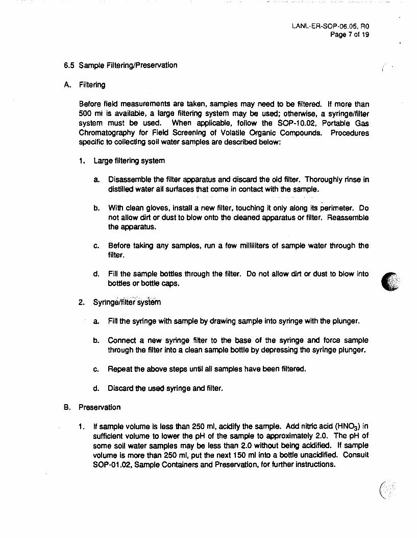
6.5 Sample Filtering/Preservation
A. Filtering
LANL-ER-SOP-06.05, RO Page 7 ot 19
Before field measurements are taken, samples may need to be filtered. If more than 500 ml is available, a large filtering system may be used; otherwise, a syringe/filter system must be used. When applicable, follow the SOP-1 0.02, Portable Gas Chromatography for Field Screening of Volatile Organic Compounds. Procedures specific to collecting soil water samples are described below:
1. Large filtering system
a. Disassemble the filter apparatus and discard the old filter. Thoroughly rinse in distilled water all surfaces that come in contact with the sample.
b. With clean gloves, install a new filter, touching it only along its perimeter. Do not allow dirt or dust to blow onto the cleaned apparatus or filter. Reassemble the apparatus.
c. Before taking any samples, run a few milliliters of sample water through the filter.
d. Fill the sample bottles through the filter. Do not allow dirt or dust to blow into bottles or bottle caps.
2. Syringe/filter system
a. Fill the syringe with sample by drawing sample into syringe with the plunger.
b. Connect a new syringe filter to the base of the syringe and force sample through the filter into a clean sample bottle by depressing the syringe plunger.
c. Repeat the above steps until all samples have been filtered.
d. Discard the used syringe and filter.
B. Preservation
1. If sample volume is less than 250 ml, acidify the sample. Add nitric acid (HN0:3) in sufficient volume to lower the pH of tha sample to approximately 2.0. The pH of some soil water samples may be less than 2.0 without being acidified. If sample volume is more than 250 ml, put the next 150 ml into a bottle unacidified. Consult SOP-01.02, Sample Containers and Preservation, for further instructions.
• ·' -,

LANL-ER-SOP-06.05, RO Page 8 of 19
2. Note the amount and type of preservative on data forms. Check the pH of the sample with pH paper to ensure that sufficient acid has been added. Once the appropriate acid has been added, seal sample bottles with electrical tape.
6.6 Obtaining Field Measurements
A. Record all field measurements and comments on the Soil Water Sampling Field Data form (Attachment B). Fill out the form as described in Attachment H. Additional comments should be noted in the Daily Activity Log form presented in SOP-01.04.
B. After the samples have been collected, measure and record pH, specific conductance, Eh, temperature, alkalinity, and 'dissolved oxygen using the instructions provided in SOP-06.02, Field Analytical Measurements of Groundwater Samples. The field measurements will be recorded directly onto the Soil Water Sampling J:ield Data form (Attachment B).
Because some sample loss will occur during testing, take measurements only if 500 ml or more are collected. Do not perform alkalinity tests unless the pH of a sample is greater than 4.5. Guard against cross-contamination.
C. After completing the field measurements, record the number of sample containers collected in the middle of the Soil Water Sampling Field Data form. Describe sample collection by volume (1 liter, 500 ml, 250 ml, or other specified volume) and by preservation method (nonacidified or acidified) and add the respective amount of acid (in milliliters) to each acidified container for sample preservation requirements.
6. 7 Postoperation
A. Ensure that all equipment is accounted for, decontaminated, and ready for shipment.
B. Restore the site to presampling conditions.
C. Make sure all soil water sampling locations are properly staked and the location ID is readily visible on the location stake.
D. Prepare samples and transport.
7.0 REFERENCES
The following procedures are directly associated with this procedure and should be reviewed prior to sampling:
LANL-ER-SOPs in Section 1.0, General Instructions. LANL-ER-SOPs in Section 2.0, Health and Safety in the Field L.ANL-ER-SOP-04.02, Hollow-Stem Auger. L.ANL-ER-SOP-04.04, Rotary Drilling.

LANL-ER-SOP-06.05, RO Page 9 of 19
LANL-ER-SOP-o6.02, Field Analytical Measurements of Groundwater Samples. ·t LANL-ER-SOP-10.02, Portable Gas Chromatography for Field Screening of Volatile Organic Compounds.
Allmaras, R. R. 1965. ·Methods of Soil Analysis. • Agronomy Monoaraoh No. 9, pt. 1 : 24-42. Am. Soc. Agronomy, Madison, Wisconsin.
EPA 1986a. RCRA Ground Water Monitoring Technical Enforcement Guidance Document. OSWER, Washington, D.C.
EPA 1986b. Test Methods for Evaluating Solid Waste, Third Edition, Vol. II. EPA Publication No. SW-846. OSWER, Washington, D.C.
Krumbein, W. C., and F. A. Graybill. 1965. An Introduction to Statistical Models in Geology, 171-181. McGraw-Hill Book Company, New York.
8.0 RECORDS
A. Completed Soil Water Sampling Field Data Form.
B. Include all field notes and other pertinent data on the Daily Activity Log presented in SOP-01.04.
9.0 ATTACHMENTS
A. Equipment and Supplies Checklist or Soil Water Samples
B. Soil Water Sampling Field Data
C. Soil Water Sampler Installation Showing Bentonite Seal
D. Soil Water Sampler Installation Showing Pressure-Vacuum Assembly
E. Purging of Slurry Water with Soil Sampler
F. Collection of Soil Water Samples
G. Soil Water Sampler Installation
H. Data Form Completion
ATTACHMENT A LANL-ER-SOP-06.05, RO
Page 10 of 19
EQUIPMENT AND SUPPLIES CHECKLIST FOR SOIL WATER SAMPLES
Complete lysimeter assembly, PVC Schedule 40 or Schedule 80
Porous ceramic cup(s)
Ceramic plug(s)
Body tube, PVC
1/4-inch-diameter Teflonnc tubing
Teflonnl tape
Vacuum pump
Pinch clamps
4-inch auger
3/16-lnch-10 x 1/8-inch wall neoprene tubing
Tamping rod
Distilled water
Bentonite pellets
pH paper
Sample containers and preservatives
pH meter
Alkalinity test kit
Thermometer
Filter assembly
0.45-micron filters
Nitric acid (HN~)
Soil Water Sampling Field Data Forms
ATTACHMENT A, Continued LANL-ER-SOP-06.05, RO
Page 11 of 19
EQUIPMENT AND SUPPLIES CHECKLIST FOR SOIL WATER SAMPLES (Continued)
Daily Activity Logs
Chain-of-Custody/Request for Analysis forms
Sample Collection Logs
Variance Logs
Custody Seals
Unique Sample Stickers
Sample Labels
Any additional supplies listed in associated procedures, as needed.

• . . .
Date:------
SOIL WATER SAMPLING FIELD DATA
LOS ALAMOS NAnONAL LABORATORY ENVIRONMENTAL RESTORAnON
SOIL WATER SAMPUNG FIELD DATA
AITACHMENTB LANL·ER-SOP-06.05, RO
Page 12 of 19
Sheet __ of __
Technical Area-----
Site Work Plan: ______________ _
Operable Unit ____ _
..--·~···! i···········m···········! l LAIT SAIIU l L..~.~ ... .! Signature: ________________ _ = ••••••••••••••••••••••••••••••••• :
FINAL FIELD VALUES:
Ec (umhos/cm) ------,~-=--~---
Eh (mvolts) -----.::~-...,.1-1;;;...:::'---
Te!Tl) ("C) --------t+---"7""'rAikali~l Ca~) ---------.,~~'+Dissotv:~(:\119'1) --------H-
Volume Sample CoUected --------
Vacuum applied----------~on~bn ________ __
~pRS!ZE NUMBER OF O~:ER
. 500~.{>-1 ----- ~!DIFIEO VOL ACID !mil
CONTAINERS
' ...... 250 ml 11., 0~
COLLECTED:
SPECIFY OTHERS:
COMMENTS: ------------~-'1-.a.J}¥:i~"x:---------
(J CHECK HERE IF CONTINUED ON BACK OF THIS SHEET

ATIACHMENTC LANL-ER-SOP-06.05, RO
Page 13 of 19
SOIL WATER SAMPLER INSTALLATION SHOWING BENTONITE SEAL (
r•--- UfiVI 10~
-
,, ... 10~
~--- IIIATIVI 101\
M+---- IU. TIVI IOU,

·i t
{
C. .•
.·
(
ATIACHMENT 0 LANL-ER-SOP-06.05, RO
Page 14 of 19
SOIL WATER SAMPLER INSTALLATION SHOWING PRESSURE-VACUUM ASSEMBLY
l"t• LD. a 111• W&~ IIIIO,•CMI TWI TWO t• (WINIWWU.I-TMI liQ'D •oa UGM UWII\.IJl
"'IIIUII•UCUW MAND 'VMP. WttM iMC UGWM DIAL eAU .. ADA,TIJl WOU•TID OM,.,_
.. . . . .... , .. :. ·•·.·
'•llauat-¥ACUUII 10&. -----T-..... WAfllll UW"\.IJl
... . .
.. . . .. ~ .. :··. ..
.: .·· .,
: ·.
. .
•'
.,__ ........

ATTACHMENT E LANL-ER-SOP-06.05, RO
Page 15 of 19
PURGING OF SLURRY WATER WITH SOIL SAMPLER
PINCM CI.AW~ ~,IN --r <P•UI. UC. ACCIII
TUIIJ
P .. CM cuw• CI.OIII , ...... UC. ACCIII fUll)
'INCN cuw• CI.OIID CIIICN&a.l AC:CIII TUIIJ
c·

COLLECTION OF SOIL WATER SAMPLES
AITACHMENT F LANL-ER-SOP-06.05, RO
Page 16 of 19
'lltCM CUM' O'IM (J .. III. UO. ACOIII TUII)
COUIOTID 11UTC•
,--a~~~··~

D&PTM ll •n·•
-
SOIL WATER SAMPLER INSTALLATION
o•OUMO•UP ICATIYI 10~
o•ou•o·u• lilA tiYI 101.
AITACHMENTG LANL-ER-SOP-06.05, RO
Page 17 of 19
(
•
DATA FORM COMPLETION
ATIACHMENTH LANL-ER-SOP-06.05, RO
Page 18 of 19
Use an indelible dark ink pen. Make an entry in each blank. For entry blanks for which no data are obtained, enter UNK for Unknown, NA for Not Applicable, or NO for Not Done. To change an entry, draw a single line through it, add the correct information above it, and date and initial the change. For all forms, complete the following information:
1. Technical Area (TA). Two-digit number indicating theTA in which the sampling is being done or sample is ~ing studied.
2. Operable Unit. Four-digit number indicating the Operable Unit in which the sampling is being done or sample is being studied.
3. Sample Identification:
• If the Daily Activity Log addresses only one sample, attach a sticker from the batch of stickers that match the sticker number on the sample, and line through the box labeled ·Attach Last Sample Number Here.·
• If the Daily Activity Log addresses a sequential number of samples, put the first matching sample sticker in the box marked ·Firsr and put the last matching sample sticker in the box marked •Last. •
• If sample identifiers used are not sequential, be sure to affix the lowest sample sticker number in the left box, record the remaining sample identifiers on the form and Daily Activity Log, and line through the •Lasr box.
4. Log Date and Time. The date and time when the measurement was made, in the following formats: 00-MMM-YY (e.g., 01-JAN-91) and the 24-hour clock time (0837 for 8:37 a.m. and 1912 for 7:12 p.m.).
5. Sheet Number. Number all the sheets that are used for this activity, by day or by some practical unit.
6. Weather and other comments. Record all other conditions pertinent to the sample collection in this section on the Daily Activity Log presented in SOP-01.04.
7. Volume Sample Collected (ml). The amount of sample collected recorded in milliliters.
8. Vacuum Applied. Record the vacuum applied to the soil water sampler to collect a sample in centibars.
9. pH. The pH of the water sample at the time of collection.

ATTACHMENT H, continued LANL-ER-SOP-06.05, AO
Page 19 of 19
10. Ec (J.Ullhos/cm). The specific conductance of the water sample in micromhos/cm at the time of collection.
11. Eh (Mvolts). The redox potential of the water sample in millivolts at the time of collection.
12. Temp. rc). The temperature of the water sample in degrees Celsius at the time of collection.
13. Alkalinity (rng/1 CaCo3). The alkalinity of the water sample in milligrams per litertc at the time of collection.
14. Dissolved Oxygen. The dissolved oxygen content of the water sample in milligrams per liter (mg/1) at the time of collection.
15. Location Description. Approximate location of soil water sampler with respect to some known geographic location.
16. Nonacidified. Number of sample containers filled using the specified field preparation method.
17. Acidified. Number of sample containers filled using the specified field preparation method.
18. Vol Acid (ml). Volume of acid in millileters (ml).
19. Specify Others. Any other types of sample containers filled.
•
(
... '
Los Alamos National Laboratory
Environmental Restoration Program No: LANL-ER-SOP-06.06 Rev: 0
Standard Operating Procedure
Tensiometer (Soil Suction Monitor)
Installation and Measurement
;
Preparer: ~HI e, {J)~ (Print Name)
~k.~Lv-1lt9 (Signature) (Date)
I
Quality Review by: .z y-u..C~ G-~ l (cdt.-f;Y ·~~~atlfa~ cr/3ol1t
(Print Name) (Signature) (Date)
I .. ,. Technical /Jv; J. ~ad.:~ 4L_,t /}~~ /~L Review by:
(Print Name) (Signature) (0 9)
Technical ~u.2 to·tb·9 I Review by: -
(Print Name) (Signature) (Date)
QPPL tfpm L~tJ /{fl/th}/~ '3/3/1-2 Approval: (Print Name) (Signature) (Date)
PM 11_ 6 ~ rf W t/oe-tt-t' /J?-/ vt:L- :l-]"'-9l-Approval: (Print Name) (Signature) (Date)
Effective Date: 3-\~~'1').
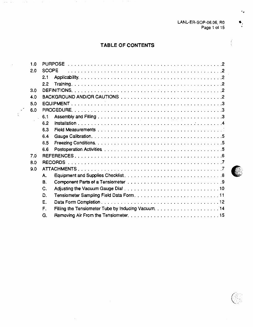
TABLE OF CONTENTS
LANL-ER-SOP-06.06, RO Page 1 of 15
1.0 PURPOSE ............................................... 2 2.0 SCOPE ............................................... 2
2.1 Applicability. . . . . . . . . . . . . . . . . . . . . . . . . . . . . . . . . . . . . . . . . . . .2 2.2 Training .............................................. 2
3.0 DEFINITIONS .............................................. 2 4.0 BACKGROUND AND/OR CAUTIONS ............................... 2 5.0 EQUIPMENT . . . . . . . . . . . . . . . . . . . . . . . . . . . . . . . . . . . . . . . ....... 3 6.0 PROCEDURE .............................................. 3
6.1 Assembly and Filling ...................................... 3 6.2 Installation ................................... : ........ 4 6.3 Field Measurements ...................................... ~ 6.4 Gauge Calibration ........................................ 5 6.5 Freezing Conditions. ...................................... 5 6.6 Postoperation Activities. .................................... 5
7.0 REFERENCES ............................................. 6 8.0 RECORDS . . . . . . . . . . . . . . . . . . . . . . . . . . . . . . . . . . . . . . . . ....... 7 9.0 ATTACHMENTS ............................................ 7
A. Equipment and Supplies Checklist. . . . . . . . . . . . . . . . . . . . . . . . . . . . . . 8 B. Component Parts of a Tensiometer . . . . . . . . . . . . . . . . . . . . . . . . . . . . . 9 C. Adjusting the Vacuum Gauge Dial . . ........................... 10 D. Tensiometer Sampling Field Data Form .......................... 11 E. Data Form Completion . . . . . . . . . . . . . . . . . . . . . . . . . . . . . . . . . . . . 12 F. Filling the Tensiometer Tube by Inducing Vacuum. ................... 14 G. Removing Air From the Tensiometer ............................ 15
... , •
('
'.•
(
• .. · ,~
LANL-ER-.SOP-06.06, RO Page 2 of 15
TENSIOMETER (SOIL SUCTION MONITOR) INSTALLATION AND MEASUREMENT
1.0 PURPOSE
This procedure defines a method of placement, installation, and operation of soil suction monitors (tensiometers) for measurement of soil moisture potential for use in the Environmental Restoration (ER) program.
2.0 SCOPE
2. 1 Applicability
This procedure is apj.1licable for operating tensiometers for the ER program.
2.2 Training
The field team leader is responsible for monitoring the proper implementation of this procedure. The field team members should be familiar with the objectives of the sampling program and should document that they have read and understand this and the procedures in Section 1.0, General Instructions.
3.0 DEFINITIONS
A. Potentiometer: An instrument for measuring an unknown potential difference by comparison to a standard:
B. Soil hygrometer: An instrument that measures soil moisture.
4.0 BACKGROUND AND/OR CAUTIONS
The tensiometer (also known as capillary potentiometer, soil hygrometer, or soil moisture meter} is an instrument that provides a direct measurement of the negative pressure potential or suction in a soil. Tensiometers are used when it is necessary to measure the gradient in pressure potential to determine the direction and rate of water movement in a soil profile.
The Site-Specific Work Plan contains specific details about the procedures and equipment for this SOP. Refer to the plan for the type of samples to be collected. Collection and measurement of samples and the documentation of data will be performed as described in the associated procedures.
The tensiometer measures the matric potential (capillary potential) of a soil for suction values between 0.1 and 1 bar. The measured matric potential can be used with soil moisture content data to construct a soil moisture characteristic curve for vadose-zone characterization and modeling.

LANL-ER-SOP-06.06, RO Page 3 of 15
A specific discussion of tensiometer locations, installation depths, sampling methods, and other ( details concerning the deployment of tensiometers at installation sites is contained in the SiteSpecific Work Plan.
5.0 EQUIPMENT
Equipment to implement this procedure is listed in Attachment A. Attachment 8 shows the components of a tensiometer.
6.0 PROCEDURE
A. A&Semble the equipment and supplies listed in Attachment A. Ensure the proper operation cf _all sampling equipment.
B. Pack tensiometers so that dial gauges and ceramic tips are not damaged during shipment to the site. Wrap Individual tensiometer pieces separately in paper and package the tensiometers securely inside the shipping boxes. Prevent ceramic tips from contacting grease or similar material that would clog the pores.
6.1 Assembly and Filling
The component parts of a tensiometer are shown in Attachment B. To assemble the tensiometers, follow the steps below.
A. Before assembling the tensiometer, make sure all parts are clean and have not been damaged in shipping. Do not use any damaged equipment.
B. Screw the vacuum dial gauge into the threaded port in the side of the body tube until the backup washer on the stem body touches the body tube. Do not overtighten the dial gauge in the body tube; the 0-ring on the stem ensures a tight vacuum seal.
C. Screw the ceramic tip into the body tube to the desired length.
D. Before putting the tensiometer to use, vent the dial gauge by momentarily removing the vent screw in the center of the dial gauge cover. This will adjust the dial gauge to local conditions; the gauges are usually set at sea level atmospheric conditions.
E. Use distilled water or a fluid prepared to inhibit algae growth that shows air bubble accumulation to fill the tensiometers. Allow the tensiometer body tube to remain in a vertical position until fluid completely saturates the ceramic tip and drips from the end of the tip for about 5 minutes.
F. Once the tip is saturated, fill the tube completely with distilled water and pull a vacuum
/
within the top of the tensiometer using the vacuum hand pump. After each pumping (-- . with the vacuum hand pump, refill the tensiometer completely to the top with water.
(.
I ' '
"
LANL-ER-SOP-06.06, RO Page 4 of 15
Repeat pumping four or five times or until no further air is seen bubbling from the stem of the dial guage. If the hand pump is not available, air can be adequately removed from the tensiometer by pushing the reservoir button down repeatedly after the tensiometer and reservoir have been filled.
G. Screw the fill reservoir cap into the top of the tube body.
H. Peel the neoprene reservoir cover back and fill the reservoir approximately 75% full. Replace the neoprene cover back over the fill reservoir cap and push the reservoir button (Attachment B) down several times to remove air from the reservoir pump cylinder and any accumulated air in the tensiometer.
I. Repeat the vacuum/pumping operation four or five times until there are no further air bubbles from the stem of the vacuum gauge.
J. Because commercial gauge-type tensiometers generally are not corrected for the length of the tensiometer, adjust the dial on the vacuum gauge to zero (Attachment C) when the tip of the tensiometer is immersed in water.
K. If the tensiometer will not be installed immediately, store it with the ceramic tips immersed in distilled water or covered with a plastic bag to prevent evaporation.
6.2 Installation
A. In soft, friable soils, push the shorter tensiometers directly into the ground.
B. In firm soils, core a hole in the soil to accept the tensiometer. The hole must be the right size for a snug fit between the ceramic tip and the soil. An insertion tool or length of standard 1/2-inch water pipe may be driven into the soil to create the hole.
C. If rocky soil is encountered, seek an adjacent location for more workable soil. If the soil is rocky, then use a 4-inch soil auger to produce a tensiometer hole. Pass the removed soil through a 1/4-inch screen to remove large pebbles and rocks. Replace the screened soil as close to its original position as possible.
D. For deep installations or installations in rocky soils, produce a slurry of water and clean silica flour and pour it into the bottom of the hole. Push the ceramic tip into the slurry to ensure good contact in the soil. Pull up gently on the probe to check the strength of the suction. Repeat steps if probe releases easily.
E. Tamp the soil around the tensiometer into place to guard against water channeling down the hole. The soil around the tensiometer should not be compacted tightly during installation.
LANL-ER-SOP-06.06, AO Page 5 of 15
F. After installation, several hours may be required before the tensiometer reads the correct soil suction value. Additional time may be required when a slurry is used. The correct value will be known when the water in the ceramic tip has come into equilibrium with the soil solution and the vacuum gauge reads a constant value. Correct readings will be reached more quickly in moist soils than in dry soils.
G. Install surface casing and locking caps to protect the tensiometers.
6.3 Field Measurements
Most tensiome~ars have a dial-type manometer to indicate the pressure potential. Their scale is given in centibars, from 0 to -100. Therefore, -50 centibars equals -0.5 bar, which is equivalent to a pressure potential of -500 em water. Record tensiometer pressure potentials on the Tensiometer Sampling Field Data form (Attachment D). Use the Data Form Completion, Attachment E, for detailed instructions. For additional comments, use the Daily Activity Log (SOP-01.04).
6.4 Gauge Calibration
The tensiometer suction pressures are measured using a Bourdon tube gauge. These gauges are calibrated by the manufacturer. Zero adjustment of the gauges may be rechecked after they are taken out of the soil (before the onset of freezing conditions) by placing the ceramic tip ih distilled water. The gauge should read zero.
Check, recalibrate, or replace tensiometers when the following circumstances occur:
• The tensiometer has been subject to subfreezing conditions.
• There is evidence of physical damage to the gauge.
Record all calibration information on the Daily Activity Log.
6.5 Freezing Conditions
Before the onset of freezing conditions, remove tensiometers from each site. Unscrew the jet-fill reservoir cap and vacuum dial gauge, clean, and store above freezing conditions. Leave the ceramic tip and body tube in place; they can be used during the next season. Place a plastic cover over the opening of the body tube; leave the PVC casing and cap in place.
6.6 Postoperation Activities
(
A. Ensure that all equipment is accounted for, decontaminated (SOP-02.07) and ready for c· _ shipment (SOP-01.03}.

LANL-ER-SOP-06.06, RO Page 6 of 15
B. Make sure all sampling locations are properly staked and the location ID is readily visible on the location stake.
C. Return the equipment to the equipment manager. Report any malfunction or damage.
D. Deliver all forms to the field team leader.
7.0 REFERENCES
The following procedures are directly associated with this procedure arid should be reviewed bofore field operations:
LANL-ER-SOPs in Section 1.0, General Instructions. LANL-ER-SOP-02.07, General Equipment Decontamination.
Allmaras, R. R. 1965. "Bias," 24-42. In Methods of Soil Analysis, Agronomy Monograph No. 9, pt. 1. Am. Soc. Agronomy, Madison, WI.
Bouyoucos, G. J. and A. H. Mick. 1940. "An Electrical Resistance Method for the Continuous Measurement of Soil Moisture Under Field Conditions," 172. Michigan Agr. Exp. Sta. Tech. Bull, Ann Arbor, MI.
Bower, H. 1961. "A Double Tube Method for Measuring Hydraulic Conductivity of Soil In-situ Above a Water Table." Soil Sci. Soc. Amer. Proc. 25: 334-39.
Davidson, J. M., D. R. Nielsen, and J. W. Biggar. 1963. ''The Measurement and Description of Water Flow through Columbia Silt Loam and Hesperia Sandy Loam," H ilgardia 34: 607-17.
Hillel, D. 1971. Soil and Water Physical Principles and Processes. Academic Press, New York, NY.
Kdohnke, G. 1968. Soil Physics. McGraw-Hill Book Company, New York, NY.
Kirkham, D. and W. L. Powers. 1972. Advanced Soil Physics. Wiley-lnterscience, New York, NY.
Krumbein, W. C. and F. A. Graybill. 1965. An Introduction to Statistical Models in Geology, 171-81. McGraw-Hill Book Company, New York, NY.
Morrison, Robert D. ·1983. Groundwater Monitoring Technology, Procedures, Equipment and Applications, 1-7 .,TIMCO MFG, Prairie Dosac, WI.

8.0 RECORDS
A. Completed Tensiometer Sampling Field Data Form
B. Record all details including calibration on the Daily Activity Log
9.0 ATTACHMENTS
A. Tensiometer Equipment and Supplies Checklist
B. Component Parts of a Ter.slometer
C. Adjusting the Vacuum Gauge Dial
D. Tensiometer Sampling Field Data Form
E. Data Form Completion
F. Filling the Tensiometer Tube by Inducing Vacuum
G. Removing Air from the Tensiometer
LANL-ER-SOP-06.06, RO Page 7 of 15
(. <

(
I . .
c
ATTACHMENT A LANL-ER-SOP-06.06, RO
Page 8 of 15
TENSIOMETER EQUIPMENT AND SUPPLIES CHECKLIST
Tensiometer tubes:
Length: 6 inches 12 inches 18 inches 24inches 30inches 36inches 42inches 48inches SO inches Other:
Vacuum dial gauges:
Quantity:
Quantity: __ Condition: __
Ceramic tips:
Quantity: __ Condition: __
Reservoir fill caps:
Quantity: __ Condition: __
Installation. equipment:
4-inch soil auger: __
Insertion tool:
1/4-inch soil screen:
Vacuum hand pump: __
Other: --------Distilled water
Quantity: __
Tensiometer Sampling Field Data Forms
Daily Activity Logs
Chain-of-Custody/Request for Analysis Forms
Sample Collection Logs
Variance Logs
Custody Seals
Unique Sample Stickers
Sample Labels
Any additional supplies listed in associated procedures, as needed

ATIACHMENTB LANL-ER-SOP-06.06, AO
Page 9 of 15 \
( ~ COMPONENT PARTS OF A TENSIOMETER
'0' RING CAP SEAl.
DEPTH LABEL
~PORT, MOLDEOtNTO ~ SIDI WALL 0'
IOOY TUII
HEAVY, CLEAR PLASTIC COVER PLATE
VENT SC:'tEW
~VACUUM DIAL QAUGE
'"-------BACKUP WASHER
'"-------'0' AlNG STEM SEAL
'----------PLASTIC BODY TUBE
"-----------CERAMIC SENSING TIP

(
E . ;
ADJUSTING THE VACUUM GAUGE DIAL
AOJUSTINQ SCREW
ATTACHMENT C LANL-EA-SOP-06.06, AO
Page 10 of 15
TURN CLOCKWISI IF POINTER IS RIACINQ TOO HIGH
OIAI. GAUGI
ADJUSTING SCAlW
PIN
TURN COUNlEACLOCKWISE IP POINlER IS READING TOO LOW

ATTACHMENT D LANL-ER-SOP-06.06. RO
Page 11 of 15 (
TENSIOMETER SAMPLING FIELD DATA FORM
Date: _____ _
Technical Area ___ _
LOS ~UOS NAnONAL LABORATORY ENVIRONMENTAL RESTORAnON
TENSIOMETER SAMPUNG FIELD DATA
Operable Unit ___ _
SiteWortc Plan: ____________ _
Sheet __ of __
: AFFIX • WTSAIIU
Signature: ______________ _ • STICKER HERE • : ....•....•.•.... -............... ~ ;,,,,,,,_,,,,u,_oooouooooo••;
LOCATION IOOA
DESCRIPTION SAMPLE
ID DEPTH MERVAA.
(Fl) PRESSURE P'OTernAI.
(CENTEAAS}
U\~U
COMMENTS
' '
'
COMM~=---------------------------------
c a CHECK HERE IF CONTINUED ON BACK OF ~IS SHEET

1·. ': . ,.,.
DATA FORM COMPLETION
ATTACHMENT E LANL-ER-SOP-06.06, RO
Page 12 of 15
Use an indelible dark ink pen. Make an entry in each blank. For entry blanks for which no data are obtained, enter UNK for Unknown, NA for Not Applicable, NO for Not Done, etc. To change an entry, draw a single line through it, add the correct information above it, and date and initial the change. For all forms, complete the following information:
TENSIOMETER SAMPLING FIELD DATA FORM (ATTACHMENT D)
1. Technical Area (TA). Two-digit number indicating theTA in which the sampling is being done or sample is being studied.
2. Operable Unit. Four-digit number indicating the Operable Unit in which the sampling is being done or sample is being studied.
3. Sample Identification:
• If the Daily Activity Log addresses only one sample, attach a sticker from the batch of stickers that match the sticker number on the sample, and line through the box labeled "Attach Last Sample Number Here."
• If the Daily Activity Log addresses a sequential number of samples, put the first matching sample sticker in the box marked "First" and put the last matching sample sticker in the box marked "LaSt."
• If sample identifiers used are not sequential, be sure to affix the lowest sample sticker number in the left box, record the remaining sample identifiers on the form and Daily Activity Log, and line through the "Last" box.
4. Log Date and Time. The date and time when the measurement was made, in the following formats: DD-MMM-YY (e.g., 01-JAN-88), and the 24-hour clock time (e.g., 0837 for 8:37 a.m. and 1912 for 7:12p.m.).
5. Sheet Number. Number all the sheets that are used for this activity, by day or by some practical unit.
6. Weather and Other Comments. Record all other conditions pertinent to the sample collection in this section on the Daily Activity Log.
7. Depth Interval (ft). The depth from which the soil suction measurement was taken. The depth interval is measured in feet and tenths of feet from the land surface.
a. Pressure Potential (Centibars). The expression of the pressure potential relative to atmospheric pressure. The value for this data field is read directly from the gauge.
....

ATTACHMENT E LANL-ER-SOP-06.06, RO
Page 13 of 15
9. Comments. Observations or information concerning the measurement of soil suction at a specific location.
10. Comments. Any additional information.
(
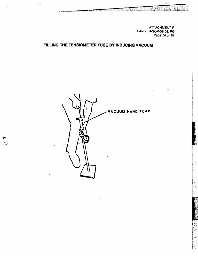
ATIACHMENTF LANL-ER-SOP-06.06, RO
Page 14 of 15
FILLING THE TENSIOMETER TUBE BY INDUCING VACUUM
VACUUM HAND PUMP
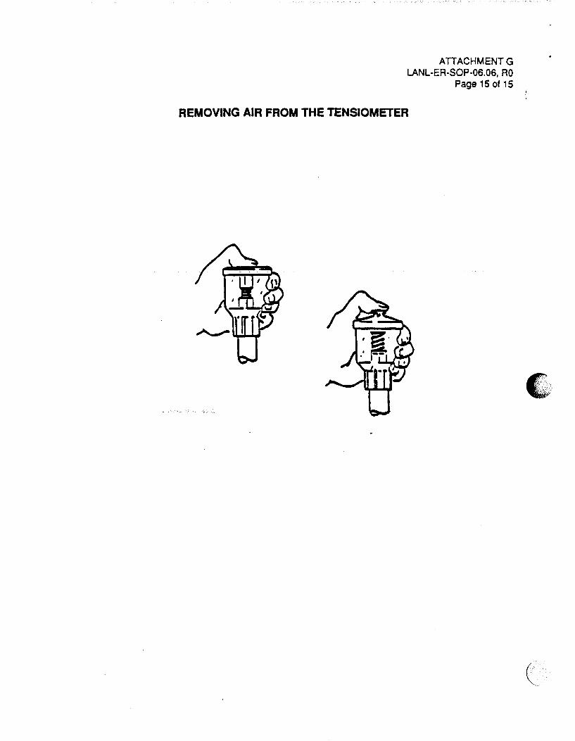
ATTACHMENT G LANL-ER-SOP-06.06, RO
Page 15 of 15
REMOVING AIR FROM THE TENSIOMETER

(
Los Alamos National Laboratory
Environmental Restoration Program
Standard Operating Procedure
No: LANL-ER-SOP-06.09 Rev: 0
Spade and Scoop Method for Collection of Soil Samples
Preparer: ~.., <M-ed• . W ~ ~ SO!JJU.-a f:. ~ I 0 -I b -CJ J (Print Name) (Signature) (Date)
Quality 0 \ n Review by: {<:.. \ c..~p. rc.\ IKo ("('.~ .. .ra
(Print Name)
Technical ~ • l ~ ~ ~ Review by: "-tlJ\1 }f t. -rresyUel.
QPPL Approval:
PM Approval:
(Print me)
~hi/~ (Signature)
Effective Date: 3 ... \ L. ~ '1 ~
3/J /1.2__ (Date)
"3- '-(-? L-(Date)

LANL-ER-SOP-6.09 Page 1 of 6
SPADE AND SCOOP METHOD FOR COLLECTION OF SOIL SAMPLES -
Table of Contents
1.0 PURPOSE .............................................................................................................. 2
2.0 SCOPE .................................................................................................................... 2 2.1 Applicability ................................................................................................ 2 2.2 Training ....................................................................................................... 2
3.0 DEFINITIONS ......................................................................................................... 2
4.0 BACKGROUND AND/OR CAUTIONS ............................................................... 2
5.0 EQUIPMENT ........................................................................................................... 2
6.0 PROCEDURE ......................................................................................................... 3
7.0 REFERENCES ....................................................................................................... 3
8.0 RECORDS .............................................................................................................. 4
9.0 ATTACHMENTS .................................................................................................... 4

( \
1.0
LANL-ER-SOP-6.09, RO Page 2 of 6
SPADE AND SCOOP METHOD FOR COLLECTION OF SOIL SAMPLES
PURPOSE
This procedure describes the spade and scoop method.
2.0 SCOPE
2.1 Applicability
This pmcedure is applicable for collection of shallow soil samples with a spade and scoop for the Environmental Restoration Program.
2.2 Training
Field team members must document that they have read and understand this procedure, and the procedures in Section 1.0, General Instructions.
3.0 DEFINITIONS
N/A
4.0 BACKGROUND AND/OR CAUTIONS
The "spade and scoop method" is simply digging a hole and collecting a grab sample from the bottom. A spade is recommended because it digs a flatter bottomed-hole than a shovel.
The spade and scoop method will work in any soil type, including cobbles (which will stop a hand auger). If a spade will not work in a given area, an alternate tool must be used. This could be a concrete saw for concrete, a pick-axe for asphalt, a maddox for roots and rocks, or a back hoe or post hole digger for deep holes or hard soil.
Holes deeper than 2 or 3 feet require much labor; a hand auger or back hoe may be more effective.
Proper back care must be exercised when digging. Work gloves may be needed to prevent blisters. Sturdy work boots are needed for pushing the spade into the ground. Goggles are needed when using a maddox, pick-axe, or concrete saw. Personnel are not to enter excavations deeper than 4 feet unless the hole is shored or terraced.
5.0 EQUIPMENT
Equipment required to implement this procedure is listed in Attachment A.

6.0 PROCEDURE
LANL-ER-SOP-6.09, RO Page 3 of 6
( A. Coordinate the sampling effort with the Sample Coordination Facility (SCF). The SCF
will give guidance regarding sample containers, preservation, and shipment to the SCF.
B. Gather and decontaminate the needed supplies and equipment (SOP-02.07, General Equipment Decontamination).
C. Using the most effective tool available, dig to the required depth. Using the scoop. dig1 down or to the side to undisturbed soil and collect the sample.
D. label sample containers and complete documentation, (SOP-01.02, Sample Containers and Preservation, and SOP-01.04, Sample Control and Field Documentation).
E. Whenever a sample is collected for chemical analyses, a custody record must be initiated on the Chain-of-Custody/Request For Analysis form and a Sample Label affixed to the sample container. SOP-01.04, Sample Control and Field Documentation, contains copies of the form and label and instructions for completing them.
F. Whenever a sample is collected, complete a description of the sample using the Borehole Log (Soil) form. An example of this form and instructions for completing form are supplied in SOP-06.12, Soil and Rock Borehole Logging and Sampling Methods. S~od all properly prepared samples to the SCF.
G. Decontaminate all equipment per SOP-02.07. Pack samples and ship them to the laboratory (SOP-01.03, Handling, Packaging, and Shipping of Samples). Return all supplies and equipment to their proper storage location.
H. Make sure all sampling locations are properly staked and the location ID is readily visible on the location stake.
7.0 REFERENCES
The following procedures are directly associated with this procedure and should be reviewed before field operations:
LANL-ER-SOPs in Section 1.0, General Instructions. LANl-ER-SOP-02.07, General Equipment Decontamination. LANl-ER-SOP-06.12, Soil and Rock Borehole logging and Sampling Methods.
' .

C.
8.0 RECORDS
LANL-ER-SOP-6.09, RO Page 4 of 6
Records generated as a result of this procedure are the completed following:
Completed Borehole Log (Soil) Form Completed Chain-of-Custody/Request for Analysis Form Completed Daily Activity Log, including any deviations or other pertinent information
9.0 ATTACHMENTS
Attachment A - Equipment and Supplies Checklist for the Spade and Scoop Method

LANL-ER-SOP-6.09, RO Attachment A Page 5 of6
EQUIPMENT AND SUPPLIES CHECK LIST FOR THE SPADE AND SCOOP METHOD
(
__ Stainless steel or disposable polystyrene {i.e., or other inert material) scoop or lab spoon (scoopulas)
__ Stainless steel shovel or fat-pointed mason trowel
__ Stainless steel spade
__ Tape measure (tenths)
__ Sturdy work boots
__ Work gloves
__ Alternate tool and eye protection (if needed)
__ Stakes, as appropriate, for identifying sample location
__ Sledge hammer for driving in stakes
__ Safety glasses TM
__ Teflon sheets or stainless steel sampling bowls
__ Plastic sheet
__ Alconox
__ Brushes (long handle, scrub, and wire)
__ Galvanized tub
__ Trash bags
__ Buckets (galvanized, stainless steel, and plastic)
__ Garden pressure sprayer
__ Cleaning wipes
__ Chern wipes
__ Storage containers for waste decontaminated solutions
__ Blue ice or equivalent
__ Disposable laboratory gloves
(

I' .,
(
LANL-ER-SOP-6.09, RO Attachment A Page 6 of 6
EQUIPMENT AND SUPPLIES CHECK LIST FOR THE SPADE AND SCOOP METHOD (continued)
__ Camera and film
__ Sample containers and preservatives
__ Borehole Log (Soil) Form
__ Daily Activity Logs
__ Chain-of-Custody/Request for Analysis Forms
__ Sample Collection Logs
__ Custody Seals
__ Unique Sample Stickers
__ Sample Labels
__ Any additional supplies listed in associated procedures, as needed

Los Alamos National Laboratory
Environmental Restoration Program Standard Operating Procedure
No: LANL-ER-SOP-06.1 0
Hand Auger and Thin-Wall Tube Sampler
Quality Review by:
Technical ~ ~ Review by: /\fyf 4_..c/ /Ss;.r,-, .._ ---o
(Print Name)
QPPL Approval: x~L~(J
(Print Name) ~/L~ (Signature)
Rev: 0
3/3/1~ (OatS} '
PM Approval: a?t-(~f w Voc..ko~ ~~~?L/---:--ttA-~_"-__ _?- Y-- 9 L-
=(P+rint.;:-N~a=m~e)~-~~-- (Signature) (Date)
Effective Date:-~---' l.a_-_9_1-__

,.t ..
LANL-ER-SOP-06.10, RO Page 1 of 8
HAND AUGER AND THIN-WALL TUBE SAMPLER
1.0 PURPOSE
This procedure defines a method of collecting subsurface solid samples with a hand auger and thin-wall tube sampler for use in the Environmental Restoration (ER) program.
2.0 SCOPE
2.1 Applicability
These procedures are applicable to personnel using this equipment for sampling tor the ER program.
2.2 Training
The field team leader is responsible for monitoring the proper implementation of this procedure. The field team members should be familiar with the equipment and must document they have read and understand this procedure and the procedures in Section 1.0, General Instructions.
3.0 DEFINITIONS
A. Thin-Wall Tube Sampler: A tool used to collect undisturbed soil samples. The sample is loaded into a stainless steel tube by the tube sampler as it is being collected. The tube is the sample container and cannot be reused. They are generally used in conjunction with a bucket auger. They cannot be used in extremely hard soil.
B. Bucket Auger: A hand auger that can be used for digging or sample collection. Most bucket augers consist of the auger bucket, various length shafts, and a "T" grip handle. All the parts are threaded and screwed together.
4.0 BACKGROUND AND/OR CAUTIONS
Undisturbed soil samples cannot be collected with a bucket auger. Thin-wall tube samplers cannot be used to dig. A subsurface undisturbed soil sample is collected by digging to six inches above the required sample depth with a bucket auger, then collecting the sample with the tube sampler. A composite or disturbed sample can be collected with the bucket auger.
To save time, a manual or powered post hole digger may be used to dig all but the last foot down to the sample depth. The post hole digger must be decontaminated per SOP-02.07. Gasoline must be handled extremely carefully during sampling events involving volatile organic (.·. compounds or fuels that are analytes.

(
C: .
"'
LANL-ER-SOP-06.10, RO Page 2 at a
Proper back care must be exercised when pulling a stuck auger out of a hole and turning an auger for long periods of time. Work gloves may be needed to prevent blisters.
5.0 EQUIPMENT
Refer to Attachment A for equipment list.
6.0 PROCEDURE
A. Coordinate the sampling effort with the Sample Coordination Facility (SCF}. The SCF will give guidance regarding sample containers, preservation, and shipment to the SCF.
B. Gather and decontaminate needed supplies and equipment (SOP.02.07, General Equipment Decontamination}.
C. To dig with the bucket auger:
1. Assemble the auger with a 2-, 3-, or 4-foot-long shaft. Put 1 /2-inch Teflonn.c tape on all threads to facilitate disassembly.
2. Press down and turn on the auger, dig down 6 to 12 inches then lift the auger out of the hole and remove the soil from the auger bucket. Experience will show how far one can dig with each auger bucket load and still get the auger out of the hole easily. Repeat until the required depth is reached adding additional shaft sections.
D. To collect a sample with the bucket auger:
1. Dig to 6 inches above the required depth. With a clean auger, dig out enough soil for the sample. Discard any soil you suspect fell down the hole and is not from the required sample depth. Put the sample material in the pan. Continue until the required sample volume is reached, then homogenize the sample and put it into the sample containers (SOP-01.02, Samples, Containers, and Preservation}.
2. When collecting a composite sample, keep the pan of soil out of the sun and covered with aluminum foil; collect all the aliquots as quickly as possible; do not decontaminate the auger between aliquots.
3. Whenever a sample is collected for chemical analyses, a custody record must be initiated on the Chain-of-Custody/Request for Analysis form and a Sample Label affixed to the sample container (SOP-01.04, Sample Control and Field Documentation}.
4. Whenever a sample is collected, complete a description of the sample using the Borehole Log (Soil) Form. An example of this form and instructions for completing this form are supplied in SOP-06.12, Soil and Rock Borehole Logging and Sampling Methods.

E. To collect undisturbed samples:
LANL-ER-SOP-06.10, RO Page 3 of 8
1. Dig to the required depth. Assemble the tube holder with the appropriate tube inside and attach the tube holder to the auger shaft. Use TeflonTM tape on the threads. Shove or pound the tube holder into the ground until it is full. When pounding, use a plastic hammer and use caution so as not to damage the equipment. If the sample is to be from the surface, remove any rocks, sticks or leaves, then drive the sampler into the ground.
2. Disassemble the tube holder being careful not to let any soil fall out of the tube. Cover the ends of the sample tube with 2-inch-wide TeflonTM tape ti1en put plastic caps over the tape. Lable the bottom end of the tube with "open this end."
F. Label sample containers and complete documentation (SOP-01.04).
G. Decontaminate equipment (SOP-02.07). Pack samples and ship them to the SCF (SOP-01.03). Return all supplies and equipment to their proper storage location.
H. General Instructions
1. Refill the hole and restore the sampling area according to instructions provided in the site-specific work plan.
2. Make sure all sampling locations are properly staked and the location ID is readily visible on the location stake.
I. Postsampling activities
1. Ensure that all equipment is accounted for, decontaminated and ready for shipment.
2. Prepare the samples for transport to the SCF per SOP-01.03.
7.0 REFERENCES
The following procedures are directly associated with this procedure and should be reviewed before field operations:
LANL-ER-SOPs in Section 1.0, General Instructions. LANL-ER-SOP-02.07, General Equipment Decontamination. LANL-ER-SOP-06.12, Soil and Rock Borehole Logging and Sampling Methods.
ASTM, 1990. "The 1990 Annual Book of ASTM Standards, Volume 04.08 Soil and rock; Dimension Stone; Geosynthetics, "American Society for Testing and Materials.
(.
(
(
.
' ·:., .
LANL-ER-SOP-06.1 0, RO Page 4 of 8
DeVera, E. A., B. P. Simmons, A. D. Stephens, and D. L. Storm. 1980. "Samplers and Sampling Procedures for Hazardous Waste Streams." U.S. Environmental Protection Agency report EPA 600/2-80-018, January 1980. U.S. Government Printing· Office, Washington, D.C.
8.0 RECORDS
A. Completed Chain-of-Custody/Request for Analysis Form
B. Completed Borehole Log (Soil) Form
C. Record all other pertinent information on the Daily Activity Log.
9.0 ATTACHMENTS
A. Equipment and Supplies Checklist for Sampling Soil with Hand Augers
B. Equipment and Supplies Checklist for Soil Sampling with Thin-Wall Tube Samplers
C. Three Types of Augers

ATTACHMENT A LANL-ER-SOP-06.1 0, RO
Page 5 of 8
EQUIPMENT AND SUPPLIES CHECKLIST FOR SAMPLING SOIL WITH HAND AUGERS
T handle and rod attachments
Auger
Bucket type
Continuous flight
Posthole
Sample container{s)
Decontamination equipment
Sprayer
Distilled water
Scrub brush
Methanol
Disposable laboratory gloves/work gloves
Combustible gas indicator
Portable photoionization detector (PID) or flame ionization detector (FlO)
Blue ice or equivalent
Plastic sheet
Any additional supplies listed in associated procedures or health and safety plan, as needed.
Daily Activity Logs
Borehole Log {Soil) Forms
Chain-of-Custody/Request for Analysis Forms
(
c·
•• ..
ATTACHMENT A, Continued LANL-ER-SOP-06.1 0, RO
Page 6 of a
EQUIPMENT AND SUPPLIES CHECKLIST FOR SAMPLING SOIL WITH HAND AUGERS (CONTINUED)
Sample Collection Logs
Variance Logs
Custody Seals
Unique Sample Stickers
Sample Labels
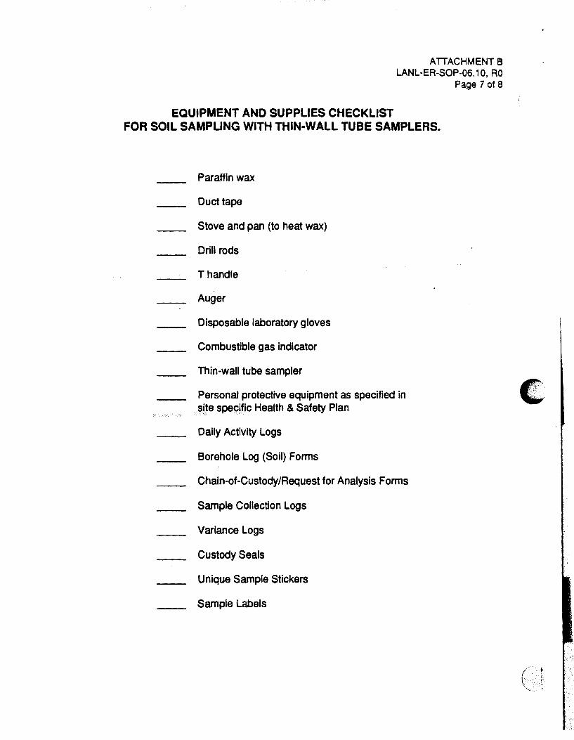
EQUIPMENT AND SUPPLIES CHECKLIST
ATTACHMENT B LANL-ER-SOP-06.1 0, RO
Page 7 of 8
FOR SOIL SAMPLING WITH THIN-WALL TUBE SAMPLERS.
Paraffin wax
Duct tape
Stove and pan (to heat wax)
Drill rods
T handle
Auger
Disposable laboratory gloves
Combustible gas indicator
Thin-wall tube sampler
Personal protective equipment as specified in site specific Health & Safety Plan
Daily Activity Logs
Borehole Log (Soil) Forms
Chain-of-Custody/Request for Analysis Forms
Sample Collection Logs
Variance Logs
Custody Seals
Unique Sample Stickers
Sample Labels
It: ....
( ..
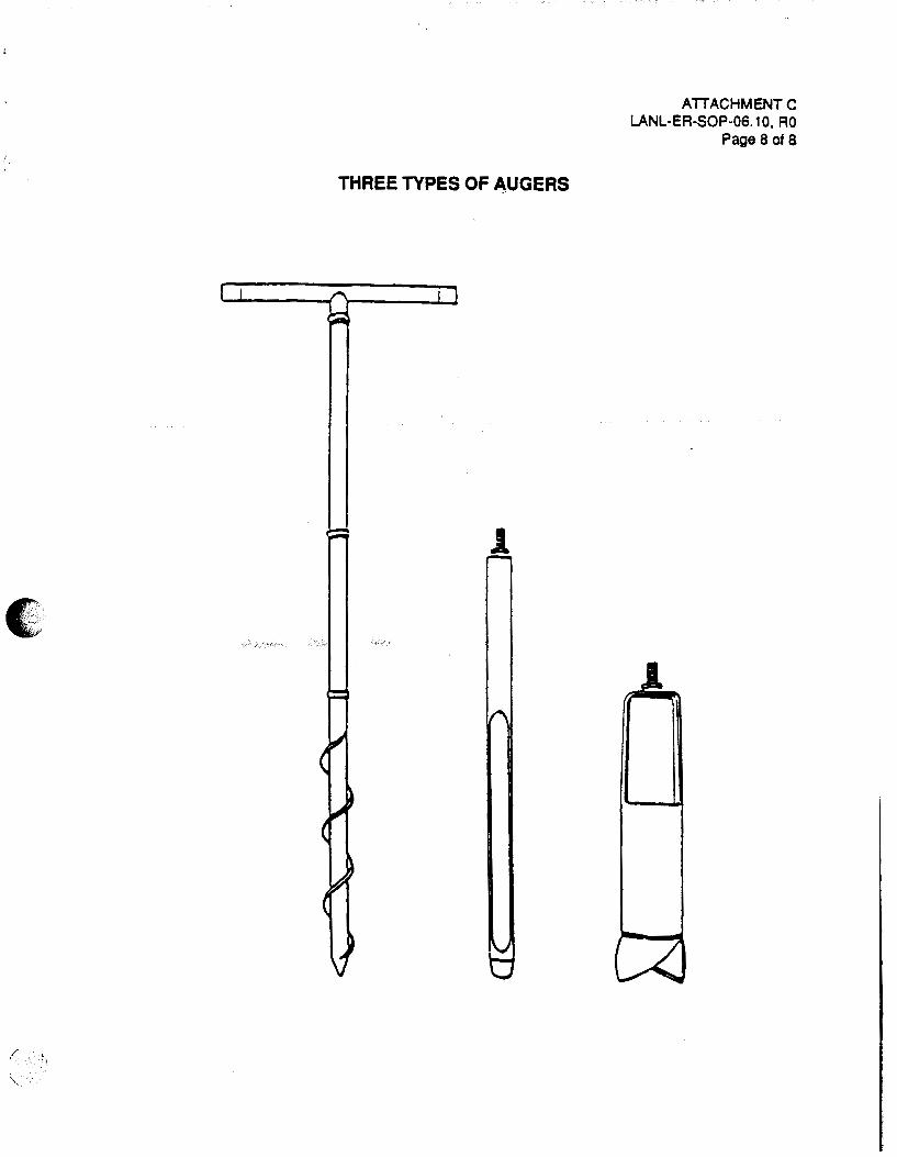
c . . '
/ ~-
THREE TYPES OF "UGERS
1
ATTACHMENT C LANL-ER-SOP-06. 10, AO
Page a at a
1

Los Alamos National Laboratory
Environmental Restoration Program No: LANL-ER-SOP-06.11 Rev: 0
Standard Operating Procedure
Stainless Steel Surface Soil Sampler
Quality ~ \ n Review by: '<.<-~~~d. \<o...,.... Q...r~
(Print Name)
QPPL Approval:
PM Approval:
(Print Name)
&/J-w~ (Signature)
Effective Date: 3 - \ l., 9. }-
3/J(1J_ ( ate
5-~-9 (Date)

LANL-ER-SOP-06.11, RO Page 1 of 4
STAINLESS STEEL SURFACE SOIL SAMPLER
1.0 PURPOSE
This standard operating procedure describes the use of a surface soil ring sampler, for the Environmental Restoration (ER} program.
2.0 SCOPE
2.1 Applicability
This standard operating procedure applies to all personnel who collect surface soil samples for the ER program.
2.2 Training
All field team members involved with this procedure must document that they have read and understand this procedure, and the procedures in Section 1.0, General Instructions.
3.0 DEFINITIONS
A. Surface Soil Ring Sampler: A sampler constructed of machined stainless steel. It has thin walls but is strong enough to withstand the force of being driven into the ground with a 1 apound drive hammer. The rings are typically 3 to 4 inches in diameter and 2 to 8 inches long.
4.0 BACKGROUND AND/OR CAUTIONS
The surface soil ring sampler is used for undisturbed soil samples or for when accurate or precise control of the collection depth or volume of a soil sample is required.
5.0 EQUIPMENT
Equipment required to implement this procedure is listed in Attachment A.
6.0 PROCEDURE
A. Coordinate the sampling effort with the Sample Coordination Facility (SCF). The SCF will give guidance regarding sample containers, preservation and shipment to the SCF.
B. Gather and decontaminate the necessary supplies and equipment (SOP-02.07, General Equipment Decontamination).
C. Assemble the sampler.
(
(

(
LANL-ER-SOP-06.11, RO Page 2 of 4
D. Remove any undesired surfical material from the sample location. Drive the sampler into the ground until the top touches the ground surface. Using the gardener's trowel, dig the soil from around the ring. Next, dig a hole beside the ring that is large enough to accomodate the ring sampler trowel. Slide the ring sampler trowel under the ring sampler keeping it tight against the bottom of the ring sampler. With the trowel underneath, lift the ring sampler out of the ground.
E. For the physical analysis of an undisturbed sample, transport the sample in the ring. For chemical analysis break up the sample with the spoon or scoop and containerize it. Consult the SCF and SOP-01.02, Sample Containers and Preservation, for guidance regarding the type of sample container, holding time, and preservation techniques to be used.
F. Label sample containers and complete documentation (SOP-01.04, Sample Control and Field Documentation).
G. Whenever a sample is collected, describe the location and sample using the Location Information and Borehole Log (Soil) forms provided in SOP-06.12.
H. Make sure all sampling locations are properly staked and the sample ID is readily visible on the location stake.
I. Decontaminate the equipment. Pack samples and ship them to the SCF. Return all supplies and equipment to their proper storage location.
7.0 REFERENCES
The following procedures are directly related to this procedure and should be reviewed before field operations:
LANL-ER-SOPs in Section 1.0, General Instructions. LANL-ER-SOP-02.07, General Equipment Decontamination. LANL-ER-SOP-06.12, Soil and Rock Borehole Logging and Sampling Methods.
Soiltest Environmental Division, 1986. "Test Instrumentation and Equipment." Soiltest Environmental Division report, Evanston, IL.
8.0 RECORDS
A. Completed Chain-of-Custody/Request for Analysis Form.
B. Completed Borehole Log (Soil) Form.
C. All pertinent information will be included on the Daily Activities Log found in SOP 01.04.

, : I f · ~ ', o • i' .' ·, •
9.0 ATTACHMENTS
LANL-ER-SOP-06.11, RO Page 3 of 4
A. Equipment and Supplies Checklist for the Stainless Steel Surface Soil Sampler
(
, ...,
(

( {
I ...
EQUIPMENT AND SUPPLIES CHECKLIST
ATTACHMENT A LANL-ER-SOP-06.11, RO
Page 4 of 4
FOR THE STAINLESS STEEL SURFACE SOIL SAMPLER
__ Stainless steel ring sampler
Stainless steel trowel --
__ Stainless steel sampler top
__ Drive hammer (3 lbs or 10 lbs)
__ Gardener's trowel
__ Plastic sheets or stainless steel sampling trays
Decontamination solutions and distilled water --__ Brushes (long-handled scrub or wire)
__ Galvanized tub
__ Trash bags
__ Buckets (galvanized, stainless steel, and plastic)
__ Garden pressure sprayer
__ Cleaning wip~$ ..
__ Kimwipes
__ 55-gallon drums
__ TeflonTM or stainless steel scoop or spoon
__ Borehole Log (Soil) Forms
__ Daily Activity Logs
__ Chain-of-Custody/Request for Analysis Forms
__ Sample Collection Logs
__ Variance Logs
__ Custody Seals
__ Unique Sample Stickers
__ Sample Labels
__ Any additional supplies listed in associated procedures

(
I I
"·
Los Alamos National Laboratory
Environmental Restoration Program
Standard Operating Procedure
No: LANL-ER-SOP-06.13 Rev: 0
Surface Water Sampling
Preparer:~ch--eJC. Wa.~'Mr ~C.Wf1 tvlb'9/ (Print Name) (Signature) (Date)
Quality ~' l' n ('_ Review by:lf ''. rfeSQUf2.
(Print N me)
Technical \ , / /_;7 Review by: /r_,{.4.v .l~o,-.·.!.!l.._.....'=>
QPPL Approval:
PM Approval:
(Print Name)
(Date)
~/U~x:r tohv/z; (Signature) (Dafe) I
(Signature)
Effective Date: 3 - \ lt · q ~

SURFACE WATER SAMPLING
1.0 PURPOSE
LANL-ER-SOP-06.13, RO Page 1 at 9
This procedure describes methods of sampling surface water bodies and documenting aU aspects of surface water sample collection.
2.0 SCOPE
2.1 Applicability
This procedure is applicable for collect:on of surface water samples for the Environmental Restoration program.
2.2 Training
The field team leader and field team members should be familiar with the objectives of surface water sampling at the specific site, and must document that they have read and understand this procedure and the procedures in Section 1.0, General Instructions.
3.0 DEFINITIONS
A. Surface water samples: Water collected from streams, ponds, lagoons, seeps, springs, rivers, lakes, or other water flowing or impounded at the ground surface comprise surface water samples.
B. Grab samples: A specific location at a given time is represented by a discrete aliquot. The sample is collected all at once and at only one particular point in the sample medium.
4.0 BACKGROUND AND/OR CAUTIONS
The preferred method for collecting surface water samples uses a peristaltic pump. The pump system allows the union of the filtration assembly with the pump and the sample container. In this method, surface samples are filtered if needed, and collected directly with minimal elapsed time. With a peristaltic pump, only inert materials contact the sample. The acceptable tubing is medical grade silicon, which is replaced after every sample.
An alternate method for this sampling is to collect surface water as grab samples. This method involves dipping a breaker, dipper, or other transfer device into the surface water to retrieve samples. The water sample can also be collected directly by dipping the collection bottle into the water and filling, removing, and capping it. This method has several drawbacks, including problems associated with sampling shallow waters like seeps, springs, or shallow streams. The likelihood of extensive air contact during the filtering of a sample and the time lapse before (
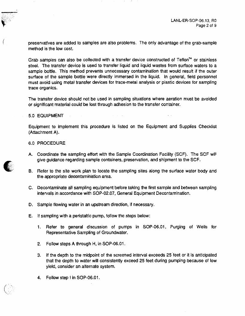
(
LANL-ER-SOP-06.13, RO Page 2 of 9
preservatives are added to samples are also problems. The only advantage of the grab-sample method is the low cost.
Grab samples can also be collected with a transfer device constructed of Teflon™ or stainless steel. The transfer device is used to transfer liquid and liquid wastes from surface waters to a sample bottle. This method prevents unnecessary contamination that would result if the outer surface of the sample bottle were directly immersed in the liquid. In general, field personnel must avoid using metal transfer devices for trace-metal analysis or plastic devices for sampling trace organics.
The transfer device should not be used in sampling situations where aeration must be avoided or significant material could be lost through adhesion to the transfer container.
5.0 EQUIPMENT
Equipment to implement this procedure is listed on the Equipment and Supplies Checklist (Attachment A).
6.0 PROCEDURE
A. Coordinate the sampling effort with the Sample Coordination Facility (SCF). The SCF will give guidance regarding sample containers, preservation, and shipment to the SCF.
8. Refer to the site work plan to locate the sampling sites along the surface water body and the appropriate decontamination area.
C. Decontaminate all sampling equipment before taking the first sample and between sampling intervals in accordance with SOP-02.07, General Equipment Decontamination.
D. Sample flowing water in an upstream direction, if necessary.
E. If sampling with a peristaltic pump, follow the steps below:
1. Refer to general discussion of pumps in SOP-06.01, Purging of Wells for Representative Sampling of Groundwater.
2. Follow steps A through H, in SOP-06.01.
3. If the depth to the midpoint of the screened interval exceeds 25 ·feet or it is anticipated that the depth to water will consistently exceed 25 feet during pumping because of low yield, consider an alternate system.
4. Follow step I in SOP-06.01.
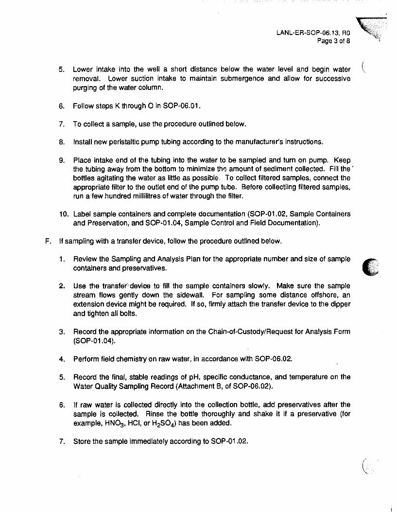
LANL-ER-SOP-06.13, RO 'k~i Page 3 of 8 "'~l
5. Lower intake into the well a short distance below the water level and begin water ( removal. Lower suction intake to maintain submergence and allow for successive purging of the water column.
6. Follow steps K through 0 in SOP-06.01.
7. To collect a sample, use the procedure outlined below.
8. Install new peristaltic pump tubing according to the manufacturer's instructions.
9. Place intake end of the tubing into the water to be sampled and turn on pump. Keep the tubing away from the bottom to minimize th'3 amount of sediment collected. Fill the' bottles agitating the water as little as possible, To collect filtered samples, connect the appropriate filter to the outlet end of the pump tube. Before collectiing filtered samples, run a few hundred millilitres of water through the filter.
10. Label sample containers and complete documentation (SOP-01.02, Sample Containers and Preservation, and SOP-01.04, Sample Control and Field Documentation).
F. If sampling with a transfer device, follow the procedure outlined below.
1. Review the Sampling and Analysis Plan for the appropriate number and size of sample containers and preservatives.
2. Use the transfer device to fil1 the sample containers slowly. Make sure the sample stream flows gently down the sidewall. For sampling some distance offshore, an extension device might be required. If so, firmly attach the transfer device to the dipper and tighten all bolts.
3. Record the appropriate information on the Chain-of-Custody/Request for Analysis Form (SOP-01.04).
4. Perform field chemistry on raw water, in accordance with SOP-06.02.
5. Record the final, stable readings of pH, specific conductance, and temperature on the Water Quality Sampling Record (Attachment B, of SOP-06.02).
6. If raw water is collected directly into the collection bottle, add preservatives after the sample is collected. Rinse the bottle thoroughly and shake it if a preservative {for example, HN03, HCI, or H2S04) has been added.
7. Store the sample immediately according to SOP-01.02.
(

'~~ ·~· .. ' ':.:: '' ' ) '
~j;'. ~· I
c
6.1 Documentation
LANL-ER-SOP-06.13, RO Page 4 of 8
A. For each sample collected, record all field measurements and chemistry determinations on the Water Quality Sampling Record. Also, initiate a custody record on the Chain-ofCustody/Request For Analysis form, and affix a Sample Label to the sample container.
6.2 Post Operation Activities
A. Ensure that all equipment is accounted for and decontaminated in accordance with SOP-02.07.
B. Send all samples to the SCF.
C. Place a permanent reference (sampling point) marker (for example, a wooden or metal stake with flagging that includes the location and site code) as close to the sampling location as possible.
7.0 REFERENCES
The following procedures are directly associated with this procedure and should be reviewed before surface water sampling:
LANL-ER-SOPs in Section 1.0, General Instructions. LANL-ER-SOP-02.07, General Equipment Decontamination. LANL-ER-SOP-06.of;' Purglng'Of Wells' for Representative Sampling of Groundwater. LANL-ER-SOP-06.02, Field Analytical Measurements on Groundwater Samples.
Berg, E. L. 1982. "Handbook for Sampling and Sample Preservation of Water and Wastewaters," U.S. Environmental Protection Agency report EPA/600/4-82/029. U.S. Government Printing Office, Washington, D.C.
EPA. 1979. "Methods of Chemical Analysis of Water and Wastes," U.S. Environmental Protection Agency report EPA-600/4-79-020. U.S. Government Printing Office, Washington, D.C.
Korte, N., and P. Kearl. 1984. "Procedures for the Collection and Preservation of Ground-water and Surface Water Samples and for the Installation of Monitoring Wells," Bendix Field Engineering Corporation Report, Grand Junction, CO.
8.0 RECORDS
The following forms, completed, are the records generated during the use of this procedure:
A. Water Quality Sampling Record

B. Chain-of-Custody/Request for Analysis Form
C. Daily Activity Log, if appropriate
9.0 ATTACHMENTS
A. Equipment and Supplies Checklist for Surface Water Sampling
B. Water Chemistry Checklist
LANL-ER-SOP-06.13, RO ·~{ Page 5 of a
(·

/
• ' .
EQUIPMENT AND SUPPLIES CHECKLIST FOR SURFACE WATER SAMPLING
Peristaltic pump
Filtration unit
TeflonTM bore and fittings
Clean filters and prefilters
Transfer device for grab samples
2- or 5-gallon carboy container
Wooden stakes
Survey flagging
Plastic or TeflonTM bucket
Stopwatch
Sample containers and preservatives
Blue Ice or equivalent
Any additional supplies listed in associated procedures, as needed
pH and conductivity meter
ATTACHMENT A LANL-ER-SOP-06.13, RO
Page 6 of a
Disposable gloves if handling acidified sample containers
Safety glasses/splash guard
Water Quality Sampling Records
Daily Activity Logs
Chain-of-Custody/Request for Analysis Forms
Sample Collection Logs
Variance Logs

ATTACHMENT A, Continued LANL-ER-SOP-06.13, RO
Page 7 of 8
EQUIPMENT AND SUPPLIES CHECKLIST FOR SURFACE WATER SAMPLING (Continued)
Custody Seals
Unique Sample Stickers
Sample Labels
Any additional supplies listed in associated procedures, as needed

' ,.·
WATER CHEMISTRY CHECKLIST
Complete all blanks before going to the field
Reagents: Alkalinity kit
Check reagent volumes
Check glass for breakage
pH meter(s) (circle one)
Electrode full of fluid
Electrode glass intact
Immerse electrode in tap water
ATTACHMENT B LANL-ER-SOP-06.13, RO
Page 8 of 8
Calibrate electrode, rinse, fill, and replace cap
Temperature probe in tap water
Temperature probe in hot water
EC meter
Battery: OK __ Dead __
Tap water: OK __ Faulty __
Against calibration solution
Solution temp
Conductivity of solution
Hand-held thermometer
Temperature in ice water
Temperature agrees with lab thermometer
KCI solutions
Filters and tubing
Flow-through bath

e. '
( -~
Los Alamos National Laboratory
Environmental Restoration Program
Standard Operating Procedure
No: LANL-EA-SOP-06.14
Sediment Material Collection
Rev: 0
Prepll'er: S..-..:4-u t. U)toUt-~~r. u_j~ /U-!64) (Print Name) (Signature) (Date)
Quality Review by:
Technical Review by:
CPPL Approval:
PM Approval:
&:,ct-{4_,/ ~~,o ~~---o ( rint Name) (Signature)
~tr1 L l<ftriki n ~Print Name)
~~.1~ (Signature)
;)&-..
(Jlf::.: "'~ '?u ~er+- W\.loc.u ~-'1-?z_ (Signature) ( . ate)
Effective Date: 3 - \ l.- 'f)

SEDIMENT MATERIAL COLLECTION
1.0 PURPOSE
LANL-ER-SOP-06.14, RO Page 1 of 9
This procedure describes four basic methods of sediment sample collection.
2.0 SCOPE
2.1 Applicability
This procedure is applicable to all personnel who are involved in sediment material collection for the Environmental Restoration program.
2.2 Training
All field team members involved with the sediment material collection must document that they have read and understand this procedure, as well as the procedures in Section 1.0, General Instructions.
3.0 DEFINITIONS
A. Sediments: Particles derived from rocks or biological materials that have been transported by a fluid. Sedirnents include solid matter (sludges) suspended in or settled from water.
B. Composite samples: Nondiscrete samples composed of more than one specific aliquot collected at various locations or at different times. Analyzing this type of sample produces an average value for the locations or time period covered by sampling.
4.0 BACKGROUND AND/OR CAUTIONS
Sediments may be watery with no cohesion and low viscosity or they may be compacted semisolids where water is a small part of the mass. The sediment to be sampled may be many feet down at the bottom of a lake or river or it may be exposed in a dry stream bed. Because of such differences, a variety of sampling methods and equipment may be required.
Scoops and trowels provide simple, quick, and easy means of collecting a sample of a sludge or sediment. Hand corers (Attachment A) are applicable to the same situati.ons and materials; and they have the further advantage of collecting an undisturbed sample that can profile any stratification in the sample caused by changes in the deposition. Some hand corers can be fitted with extension handles that will allow the collection of samples underlying a shallow layer of liquid. Most hand corers can also be adapted to hold liners made of brass or polycarbonate plastic. Care should be taken to choose a material that will not compromise the intended analytical procedures.
'

• ' '
LANL-ER-SOP-06.14, RO Page 2 of 9
A gravity corer {Attachment B) is a metal tube with a replaceable tapered nosepiece on the bottom and a ball or other type of check valve on the top. The check valve allows water to pass through the corer on descent but prevents washout during recovery. The tapered nosepiece facilitates cutting and reduces core disturbance during penetration. Most corers are constructed of brass or steel, and many can accept plastic liners and additional weights.
Corers are capable of collecting samples of most sludges and sediments. The corers collect essentially undisturbed samples that represent the profile of strata that may develop in sediments and sludges during variations in the deposition process. Depending on the density of the substrate and the weight of the cores, penetration to depths of 75 em (30 inches) can be attained. Care should be exercised when using gravity corers in vessels or lagoons that have liners, because penetration depths could exceed depth of substrate and result in damage to the liner material.
The Ponar grab {Attachment C) is a clamshell-type scoop activated by a counter-lever system~ The shell is opened, latched in place, and slowly lowered to the bottom. When tension is released on the lowering cable, the latch releases and the lifting action of the cable on the lever system closes the clamshell.
Sediments from large surface water bodies such as streams and lakes may be taken with Ponar grab samplers from a boat. Ponar grab samplers are more applicable to a wide range of sediments and sludges because they penetrate deeper and seal better than spring activated types {e.g., Eckman dredges). Refer to equipment operations manual for use of the sampler.
v~
Ponars are capable of sampling most types of sludges and sediments from silts to granular materials. One version has a 232-square-centimeter sample area that is light enough to be operated without a winch or crane. Penetration depths will usually not exceed several centimeters. Grab samplers are not capable of collecting undisturbed samples. As a result, material in the first centimeter of sludge cannot be separated from that at lower depths. The sampling action of these devices causes agitation currents that may temporarily resuspend some settled solids. This disturbance can be minimized by slowly lowering the sampler the last half-meter and by allowing a very slow contact with the bottom. It is advisable, however, to collect sludge or sediment samples only after all overlying water samples have been obtained.
5.0 EQUIPMEMT
Equipment required to implement this procedure is listed in Attachment D, Equipment and Supplies Checklist.
6.0 PROCEDURE
6.1 Sludge or sediment sampling using scoops or trowels
A. Insert a decontaminated scoop or trowel into material and remove sample. In the case of sludges exposed to air, it may be desirable to remove the first 1 to 2 em of material

LANL-ER-SOP-06.14, RO Page 3 of 9
l
'"1 prior to collecting sample. Record any pertinent information, e.g., location, sample i size, on the Daily Activity Log (SOP-01.01.01, Records).
B. If compositing a series of grab samples, use a decontaminated glass or stainless steel mixing bowl or Teflonm tray for mixing.
C. Transfer sample into an appropriate sample container.
6.2 Sludge or sediment sampling using a hand corer
A. Push corer into material with smooth continuous motion, twist, then withdraw in a single smooth motion. Record any pertinent information in the Daily Activity Log.
B. Remove sample and place in an appropriate container.
6.3 Sediment and sludge sampling using a gravity corer:
A. Attach a precleaned corer to the required length of sample line. Solid braided 5 mm (3/16 inch) nylon line is sufficient; 20 mm (3/4 inch) nylon, however, is easier to grasp during hand hoisting.
B. Measure and mark distance to top of sludge on sampler line to determine depth of sludge or sediment coring.
C. Allow corer to free fall through liquid to bottom.
D. Determine depth of sludge penetration. Depending on the hardness and depth of the sediment and the weight and diameter of the corer, the corer may penetrate too far or not far enough. The amount of weight on the corer may need to be changed. Trial and error is required to find the correct weight for any given situation.
E. Retrieve corer with a smooth, continuous lifting motion. Do not bump corer because this may result in some sample loss . . .
F. Remove sample and place in an appropriate container. Record any pertinent information in the Daily Activity Log.
6.4 Sediment and sludge sampling using a Ponar grab sampler
A. Attach a decontaminated Ponar to the necessary length of sample line.
B. Measure and mark the distance to top of sludge on the sample line. Record depth to top of sludge and depth of sludge penetration in the Daily Activity Log.

• ~
LANL-ER-SOP-06.14, RO Page 4 of g.
C. Open sampler jaws until latched. From this point on, support the sampler by its lift line. or the sampler will be tripped and the jaws will close.
D. Begin lowering the sampler until the proximity mark is reached.
E. Use a slow rate of descent through last meter until contact is felt.
F. Allow sample line to slack several centimeters. In strong currents, more slack may be necessary to release mechanism.
G. Slowly raise sampler clear of surface.
H. Remove sample and place in an appropriate container.
6.5 Postoperation Activities
A. Label samples and complete sample documentation (SOP-01 .04, Sample Control and Documentation).
B. Prepare the samples for shipping (SOP-01.03, Handling, Packaging, and Shipping of Samples) .
C. Ensure that all equipment is accounted for, decontaminated (SOP-02.07, General EquipmenfOecontamination), and ready for shipment.
7.0 REFERENCES
The following procedures are directly associated with this procedure and should be reviewed before sediment sample collections:
LANL-ER SOPs in Section 1.0, General Instructions. LANL-ER SOP-02.07, General Equipment Decontamination.
DeVera, E. R., B. P. Simmons, R. D. Stephens, and D. L. Storm. "Samplers and Sampling Procedures for Hazardous Waste Streams." EPA 600/2-80-018. January 1980.
Environmental Monitoring System Laboratory (EMSL), ORO, U.S. Environmental Protection Agency. Characterization of Hazardous Waste Sites--A Method Manual, Volume //--Available Sampling Methods. 1983. Las Vegas, NV.
Und, Orent. Handbook of Common Methods of Limnology. C.V. Mosby Co., 1974. St. Louis, MO.

LANL-ER-SOP-06.14, RO Page 5 of 9
OWDC, U.S. Geological Survey, U.S. Department of the Interior. National Handbook of Recommended Methods for Water-Data Acquisition. Prepared cooperatively by agencies of the U.S. Government, Reston, VA. 1977.
Smith, R., and G.V. James. The Sampling of Bulk Materials. London: The Royal Society of Chemistry. 1981.
8.0 RECORDS
A. Completed Daily Activity Log which will include all pertinent information, e.g., location, sample size, and comments
B. Completed Chain-of-Custody/Request for Analysis Form
9.0 ATIACHMENTS
A. Diagram of Hand Corer
B. Diagram of Gravity Corer
C. Diagram of Ponar Grab Sampler
D. Equipment and Supplies Checklist e' •• .
(,

DIAGRAM OF HAND CORER
ATIACHMENTA LANL-ER-SOP-06.14, RO
Page 6 of 9
Check Valve
No~epiec:e
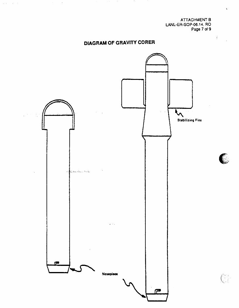
DIAGRAM OF GRAVITY CORER
-
ATTACHMENT 8 LANL-ER-SOP-06.14, RO
Page 7 of 9
r ~
~ Stabilizing Fins
' ' I
Nosepiece
(?It
\ J
c·-~
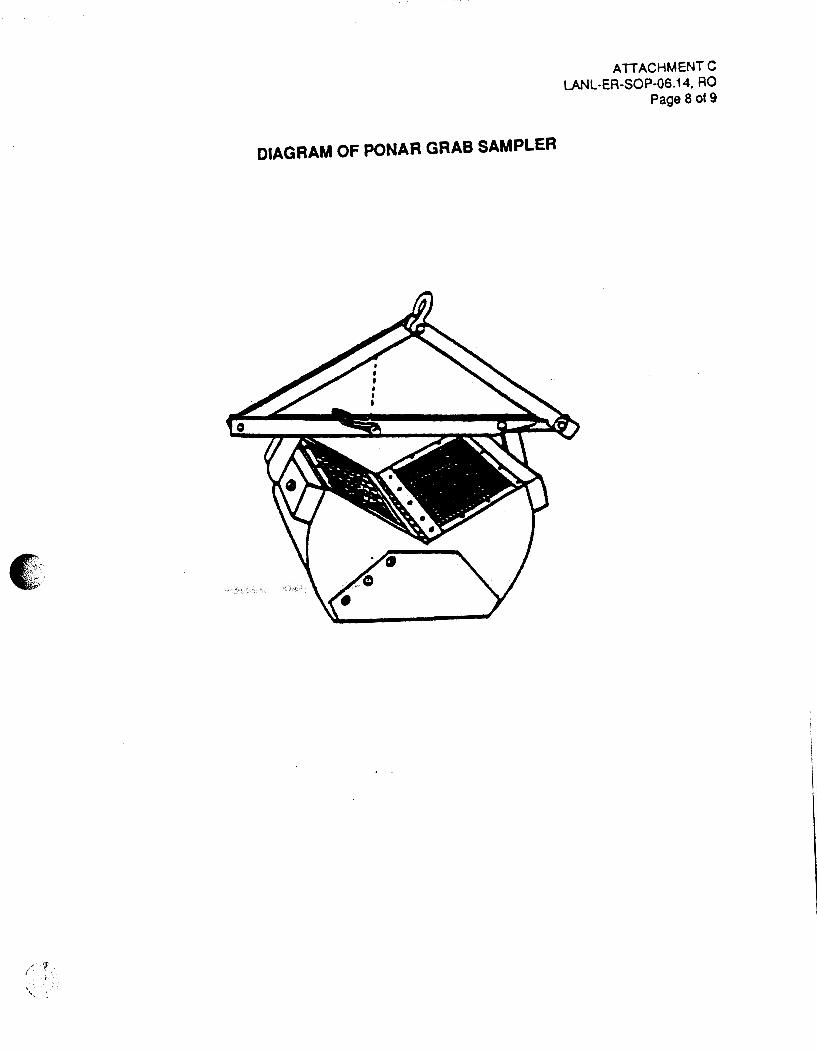
•' <
'
DIAGRAM OF PONAR GRAB SAMPLER
ATTACHMENT C LANL-ER-SOP-06.14, RO
Page a ot9

EQUIPMENT AND SUPPLIES CHECKLIST
Hand Corer or
Gravity Corer or
Ponar Grab Sampler or
Trowel or
Scoop
Operations manuals
Bowl
Tray
Sample containers
ATTACHMENT D LANL-ER-SOP-06.14, RO
Page 9 of 9
Rope (Review well depths prior to purchase)
Protective gloves
Life jacket
Tape measure
(

( \
c ' ' .
(
Los Alamos National Laboratory
Environmental Restoration Program Standard Operating Procedure
No: LANL-ER-SOP-06.15
Coliwasa Sampler for Liquids and Slurries
Quality ---;-){_ ·1· o ~ Review by: r- nt,p V'·QIAeZ
(Print N me)
Technical / /1 Review by: >./ltMI ~tlrr;;
(Print Name) ;;
QPPL i.J '" ~ tJ Approval: no.ren L WUA7N/1
PM Approval:
(Print Name)
f,/,-1- W V,t,lc~ g(J-tvv:L-'Print Name) (Signature)
Effective Date: 3 - \liz --- ,_ \....
Rev: 0
>-if-/ (Date)

LANL-ER-SOP-06.15, RO Page 1 of a
COLIWASA SAMPLER FOR LIQUIDS AND SLURRIES
1.0 PURPOSE
This procedure describes the use of the Coliwasa sampler for obtaining samples of free-flowing liquids and slurries in tanks, drums, pits, and similar containers.
2.0 SCOPE
2. 1 Applicability
This procedure is applicable to all field team members using the Composite U:Juid Waste Sampler (Coliwasa) of tree flowing liquid and slurries in tanks, drums, pits, and similar containers tor the Environmental Restoration program.
2.2 Training
The field team members should be familiar with the waste sampling objectives and must document that they have read and understand this procedure as well as the procedures in Section 1.0, General Instructions.
3.0 DEFINITIONS
N/A
4.0 BACKGROUND AND/OR CAUTIONS
The Coliwasa is designed to collect liquid hazardous waste. It permits the representative sampling of multiphase wastes of a wide range of viscosity, corrosivity, volatility, and solids content. Its simple design makes it easy to use and allows the rapid collection of samples, thus minimizing the exposure of the sample collector to potential hazards from the waste. The sampler is commercially available, as either a reuseable or disposable unit, but is relatively easy and inexpensive to fabricate. The cost of fabrication is low enough that the contaminated parts may be discarded after a single use when they cannot be easily cleaned. The use of disposable units decreases the likelihood of cross-contamination.
The main parts of the Coliwasa consist of the sampling tube, the stop-cock, and the closure system. (See Attachment A for example.) The sampling tube consists of a 5-foot (1.52-m) by 1 5/8-inch (4.13-cm) J.D. translucent plastic pipe; usually polyvinyl chloride (PVC), PTFE or borosilicate glass plumbing tube.
Coliwasas are constructed of either plastic or glass. The plastic type consists of a translucent plastic sampling tube. The glass Coliwasa uses borosilicate glass plumbing pipe as the sampling tube.

LANL-ER-SOP-06.15, RO Page 2 of a
The plastic Coliwasa is used to sample most containerized liquid wastes except wastes that contain ketones, nitrobenzene, dimethylforamide, mesityl oxide, and tetrahydrofuran.
The glass Coliwasa is used to sample all other containerized liquid wastes that cannot be sampled with the plastic Coliwasa except strong alkali and hydrofluoric acid solutions.
The Coliwasa sampler has the following limitations:
• Not suitable for sampling in containers over 5 feet (1.5-m) deep
• Cannot be used for sampling hydrofluoric acid and concentrated alkali solutions.
Site workers preparing for field operations should read and understand the procSdures outlined in LANL-ER-SOPs, Section 2.0, Health and Safety in the Field. In addition, site workers should refer to site-specific Operable Unit Health and Safety plans for the particular health and safety equipment to be used.
5.0 EQUIPMENT
See Attachment 8, Equipment and Supplies Checklist, for a list of equipment required to implement this procedure.
6.0 PROCEDURE
A. Assemble the necessary equipment and appropriate protective clothing.
B. Pack and transport the equipment to the site.
C. Decontaminate all equipment per the instructions in SOP-02.07, General Equipment Decontamination.
D. For drum and containerized liquid sampling perform the following procedure.
1. Open unknown drums using a remote drum opening device when possible.
Note: A bulging container indicates pressure and should receive special handling.
2. Draw the sample from the bung openings whenever possible.
E. Insert the Coliwasa into the desired liquid phase to be sampled and obtain the sample.
F. Transfer the sample from the Coliwasa to the sample container.

LANL-ER-SOP-06.15, RO Page 3 of 8
G. Decontaminate reusable samplers before reuse, or use a new sampler to ensure no contamination or cross-contamination.
H. Repeat steps D through G until all samples have been collected.
I. For drum and containerized materials, reclose the container.
6.1 Documentation
A. Complete Containerized Waste Sampling Forms (Attachment C). Use the Daily Activity Log from SOP-01 .04, for additional comments if necessary.
B. Complete other applicable sample forms and labels.
6.2 Post Sampling Activities
A. Ensure all equipment is accounted for, decontaminated per SOP-02.07 or disposed of properly, and ready for transport.
B. Make sure all sampling locations are properly documented.
C. Package all samples for transport to the Sample Coordination Facility (SCF) per SOP-01.03, Handling, Packaging, and Shipping of Samples. All sampling efforts must be coordinat~ witl'l th~ SCF.
D. Return the equipment to the equipment manager. Report any malfunction or damage.
E. Deliver all forms to the field team leader.
7.0 REFERENCES
The following procedures are directly associated with this procedure and should be reviewed before field operations:
LANL-ER-SOPs in Section 1.0, General Instructions. LANL-ER-SOPs in Section 2.0, Health and Safety in the Field.
EPA. November 1986, "Test Methods for Evaluating Solid Waste, • Vol. II: Field Manual Physical/Chemical Methods, Officer of Solid Waste and Emergency Response, Washington D.C.
8.0 RECORDS
A. Completed Containerized Waste Sampling Form

E. ' .'
B. Completed Chain-of-Custody/Request for Analysis Form
LANL-ER-SOP-06.15, RO Page 4 of a
C. Daily Activity Log containing deviations along with any other pertinent information
9.0 AITACHMENTS
A. Example of one type of Coliwasa
B. Equipment and Supplies Checklist
C. Containerized Waste Sampling Form
D. Data Form Completion

AITACHMENTA LANL-ER-SOP-06.15, RO
Page 5 of a
EXAMPLE OF ONE TYPE OF COMPOSITE LIQUID WASTE SAMPLER (Collwasa)
~~ Ule~~~12llo, II II . II II II II
" II II II II II II 1.u"' 11'-4"1 II II II II II II II II II II II II II II II
IAWLING IIOIITION
---t ..,_ 2ae~~~ u ,,.. .. 1
T T~le-..... 17.1-11''1
~·~~~ +. ,... _ _..II -L
II II II II II II II II II II II II II II II II II II II II II II II II II II
s. .... ._ .. _,vc O.H- llti"'J 0 D.
,, ... '\IC. • 13 C"' 11 Ill'") I. 0 •.21 CM It 7/1"') 0. 0
II ~ ..._ . ......,..__No.,.,"' ....------ JJI• I. I. er PVC 11M IIIII • ....,
I \.
(

ATTACHMENT 8 LANL-EA-SOP-06.15, AO
Page 6 of 8
EQUIPMENT AND SUPPLIES CHECKLIST FOR USING A COLIWASA SAMPLER FOR LIQUIDS AND SLURRIES
Coliwasa
Protective clothing
Remote drum opening device
Sample containers
Daily Acti·tities Logs
Containerized Waste Sampling forms
Chain-of-Custody/Request-for-Analysis forms
Sample collection logs
Variance logs
Custody seals
Unique Sample Stickers
Sample Labels

ATTACHMENT C LANL-ER-SOP-06.15, RO
Page 7 of 8
CONTAINERIZED WASTE SAMPLING RECORD
Date:------
LOS ALAMOS NATIONAL LABORATORY ENVIRONMENTAL RESTORA nON
CONTAINERIZED WASTE SAMPUNG RECORD Sheet __ of __
Technical Area---- Operable Unit-----
Site Work Plan:--------------
Signature:
Sampling Period: Sta~
Sampling Method: ~ JL?-Weighted Bottle _ f
1 __ Hand Auger
: ................................. :
AfFIX ' LA8T SAIIIU . • S1'1CIWIIERE • : ................................ :
E~ -----------
Trier
Co-111:: w~ner Information:
Total Number J~ta}'!ers -------.....fiY+~~------------Type ~ Volume ______ __:..y,,...._ ________ #-,::..;;;.c:_----::f'r--------
Origin ---------..!.oiS~=----------~'1-----::::------
Maoo~s -----------+~-------~~-~~~---~Is ------------~~~-------~~-----Other Identification -----------S~eFtt-------------Color ----------------r?--1-br------------Condition --------------~....!.I'.J..t%~-------
i?~ Sample Matrix:
_ Uquid/Siurry
_Sludge
Oil _ Other (Describe)
Sand
Packed Powder/Granules
_ Dry Powder/Granules
Moist Powder/Granules
o""t1?S'
COMMENTS: _____________________________ __
Q CHECK HERE IF CONTINUED ON BACK OF n.ts SHEET
(

DATA FORM COMPLETION
ATTACHMENT D LANL-ER-SOP-06.15, RO
Page 8 of 8
Use an indelible dark ink pen. Make an entry in each blank. For entry blanks for which no data are obtained, enter UNK for Unknown, NA for Not Applicable, or NO for Not Done. To change an entry, draw a single line through it, add the correct information above it, and date and initial the change. For all forms, complete the following information:
CONTAINERIZED WASTE SAMPLING RECORD (ATTACHMENT B)
1. Technical Area (TA). Two-digit number indicating the TA in which the sampling is being done or sample is being studied.
2. Operable Unit. Four-digit number indicating the operable unit in which the sampling is being done or sample is being studied.
3. Sample Identification:
• If the Daily Activity Log addresses only one sample, attach a sticker from the batch of stickers that match the sticker number on the sample, and line through the box labeled ·Attach Last Sample Number Here.·
• If the Daily ~Activity Log addresses a sequential number of samples, put the first rr~tching sample sticker in the box marked •First• and put the last matching sample sticker in the box marked •Last. •
• If sample identifiers used are not sequential, affix the lowest sample sticker number in the left box, record the remaining sample identifiers on the form and Daily Activity Log, and line through the •Last• box.
4. Log Date and Time. The date and time when the measurement was made, in the following formats: 00-MMM-YY (e.g., 01-JAN-88), and the 24-hour clock time (e.g., 0837 for 8:37 a.m. and 1912 for 7:12p.m.).
5. Sheet Number. Number all the sheets that are used for this activity, by day or by some practical unit.
6. Weather and other comments. Record all other conditions pertinent to the sample collection in this section on the Daily Activity Log in SOP-01.04.

• '
Los Alamos National Laboratory
Environmental Restoration Program
Standard Operating Procedure
No: LANL-ER-SOP-06.16
Thief Sampler for Dry Powders or Granules
Rev: 0
Preparer:SuHIAA-o. /:. (l,?,.~Ht ~Ht.t-~ /Or(bjj (Print Name) (Signature) (Date)
Quality Review by:
Technical Review by:
QPPL Approval:
PM Approval:
~
...iran d/?n?A ~ (Print Name) 7
/101'tn L wcvr tlia ~a) .I tutafk 2 (Print Name) (Signature)
R. ~.,~+ tJVor-J.~ (S/d:(=w~ (Print Name)
Effective Date: 3 - \ ~ - 9.. }--..
bo-23-1/ ( ate)
~ ( )
~)1~ at
3-£( .. 9 (!;)ate)

LANL -ER-SOP-06.16, RO Page 1 of 5
THIEF SAMPLER FOR DRY POWDERS OR GRANULES
1.0 PURPOSE
This procedure describes the method for using the Thief sampler for dry powders or granules.
2.0 SCOPE
2. 1 Applicability
This method is applicable to all site workers using the Thief sampler for dry powders or granules for the Environmental Restoration program.
2.2 Training
The site worker should be familiar with the sampling equipment and must document that he has read and understands this procedure as well as the procedures in Section 1.0, General Instructions.
3.0 DEFINITIONS
N/A
4.0 BACKGROUND AND/OR CAUTIONS
Thief samplers are used for low volume sampling of dry solid waste materials in bags, fiber drums, sacks, or similar containers. This sampler is most useful when the solids are no greater than 1/2 inch (0.6 em) in diameter or no larger than one-third the width of the slots. A diagram of the Thief sampler is in Attachment A.
The Thief sampler consists of two slotted concentric tubes, usually made of stainless steel or brass. The outer tube has a conical pointed tip that permits the sampler to penetrate the material being sampled. The inner tube is rotated to open and close the sampler. Thief samplers are usually 24 to 100 inches (60 to 100 em) long by 1/2 to 1 inch (1.27 to 2.54 em) in diameter.
Site workers preparing for field operations should read and understand the procedures outlined in LANL-ER-SOPs, Section 2.0, Health and Safety in the Field. In addition, site workers should refer to site-specific Operable Unit Health and Safety plans for the particular health and safety equipment to be used.
NOTE: The Thief sampler is not desirable for moist or sticky samples.
IJ .. ~\
(

5.0 EQUIPMENT
Equipment to implement this procedure is shown in Attachment B.
6.0 PROCEDURE
A. Coordinate sampling effort with Sample Coordination Facility.
B. Assemble the necessary equipment.
LANL-ER-SOP-06.16, AO Page 2 of 5
C. Decontaminate all equipment prior to beginning and after each use (SOP-02.07, General Equipment Decontamination).
D. After opening the waste containers, insert the open Thief sampler into the waste to be sampled, obtain the sample, and close the sampler.
E. Remove the Thief sampler and transfer the sample from the Thief to the sample container. Refer to SOP-01.02, Sample Containers and Preservation for guidance. Reclose the waste container.
6.1 Documentation
A. Complete the Containerized Waste Sampling forms (SOP-06.15). Use the Daily Activity Log from SOP-01.04, Sample Control and Field Documentation for additional comments~ , ··
B Complete other appropriate sample forms and labels also found in SOP-01.04.
6.2 Post Sampling Activities
A. Ensure all equipment is accounted for, decontaminated, and ready for transport.
B. Make sure all sampling locations are properly documented.
C. Package all samples for transport to the laboratory according to SOP-01.03, Handling, Packaging and Shipping of Samples.
7.0 REFERENCES
The following procedures are directly associated with this procedure and should be reviewed before field operations:
LANL-ER-SOPs in Section 1.0, General Instructions. LANL-ER-SOPs in Section 2.0, Health and Safety il1 the Field. LANL-ER-SOP-06.15, Coliwasa Sampler for Liquids and Slurries.
LANL-ER-SOP-06.16, RO Page 3 of 5
EPA. November 1986. ·rest Methods for Evaluating Solid Waste•, Vol. II: Field Manual Physical/Chemical Methods, Office of Solid Waste and Emergency Response, Washington D.C.
8.0 RECORDS
A. Completed Containerized Waste Sampling Form
B. Completed Chain-of-Custody and Request for Analysis Form
C. Daily Activity Log detailing any deviations and any other pertinent information
D. Sample Collection Log
9.0 ATTACHMENT
A. Thief Sampler diagram
B. Equipment and Supplies Checklist for Thief Sampler
(

THIEF SAMPLER
80-100 em
, .27 -u. Clft
ATTACHMENT A LANL-ER-SOP-06.16, RO
Page 4 of 5
AITACHMENTB LANL-ER-SOP-06.16, RO
Page 5 of 5
EQUIPMENT CHECKLIST FOR THIEF SAMPLING
Thief Sampler
sample container(s)
decontamination equipment
scrub brush
pan (stainless steel or glass)
disposable laboratory gloves
work gloves
plastic sheet
blue ice or equivalent
cooler
Daily Activity Log
Chain-of-Custody/Request for Analysis forms
Sample Collection Logs
Variance Logs ·
Custody Seals
Unique Sampling Stickers
Sample Labels

c . -,l
Los Alamos National Laboratory
Environmental Restoration Program
Standard Operating Procedure
No: LANL-ER-SOP-06.17 Rev: 0
Trier Sampler for Sludges and Moist Powders or Granules
Preparer: s . .....l<N~ ~. (J) •J ~t-1 S.....& ,\-.a ~ • w'f'f, Ill - ( 6-"j I (Print Name) (Signature) (Date}
QuaiHy I];~~·~u~ bo ::t?~<t I Review by: (Print me) ( ate}
Technical -..1«/Jrl t/ .t)/~4 ~~ P-Review by: (Print Name) I ( }
QPPL fvi!t11 L WcL~"ik:n ~hl)t~ 5/J.Nd-Approval: (Print Name) {Simiture) (D te)
PM !?, '<( ~f tvt/oc.-lc.l )Ju?.;ttv~ 3-t/-9 Approval: (Print Name) (Signature) (Date)
Effective Date: 3 - \ l. · 9 'l..

LANL-ER-SOP-06. 17, RO Page 1 of 5
TRIER SAMPLER FOR SLUDGES AND MOIST POWDERS OR GRANULES
1.0 PURPOSE
This procedure describes methods for using the Trier sampler for moist powders or granules.
2.0 SCOPE
2.1 Applicability
This procedure is applicable to all site workers using the Trier sampler for sampling sludges, moist powders, and granules for the Environmental Restoration program.
2.2 Training
The site workers should be familiar with the sampling equipment and must document that they have read and understand this procedure and the procedures in Section 1.0, General Instructions.
3.0 DEFINITIONS
N/A
4.0 BACKGROUND AND/OFfCAUTIONS
Trier sampler is used for sampling moist or sticky solid waste materials in bags, drums, sacks, or similar containers. A diagram of the Trier Sampler is shown in Attachment A.
A Trier consists of a long tube with a slot that extends almost its entire length. The tip and edges of the tube slot are sharpened to allow the trier to cut a core of material to be sampled when rotated after insertion into the material. A Trier sampler is most useful when the waste is moist or sticky solids with a particle diameter less than one-half the diameter of the Trier.
Site workers preparing for field operations should read and understand the procedures outlined in LANL-ER-SOPs, Section 2.0, Health and Safety in the Field. In addition, site workers should refer to site-specific Operable Unit Health and Safety plans for the particular health and safety equipment to be used.
5.0 EQUIPMENT
Equipment to implement this procedure is shown in Attachment B.
.. l
(
,
( 6.0 PROCEDURE
A. Coordinate sampling efforts with the Sample Coordination Facility.
B. Assemble the necessary equipment.
LANL-ER-SOP-06.17, AO Page 2 of 5
C. Decontaminate all equipment prior to and after each use per SOP-02.07, General Equipment Decontamination.
D. After opening the waste container, insert the Trier sampler into the waste and cut a core of the waste by rotating the sampler.
E. Transfer the sample from the Trier sampler to the sample container (SOP-01.02, Sample Containers and Preservation). A spoon or similar tool may be used to scrape the sample out of the Trier, if necessary.
F. For containerized materials, reclose the container.
6.1 Documentation
A. Complete the Containerized Waste Sampling Record (SOP-06.15). Any additional comments should be recorded on the Daily Activity Log, SOP-01.04, Sample Control and Field Documentation.
B. Complete other applicable sample forms and labels also found in SOP-01.04.
6.2 Post Sampling Activities
A. Ensure all equipment is accounted for, decontaminated, and ready for transport.
B. Make sure all sampling locations are properly documented.
C. Package all samples for transport to the laboratory, per SOP-01.03, Handling, Packaging, and Shipping of Samples.
7.0 REFERENCES
The following procedures are directly related to this procedure and should be reviewed before field operations:
LANL-ER-SOPs in Section 1.0, General Instructions. LANL-ER-SOPs in Section 2.0, Health and Safety in the Field. LANL-ER-SOP-06.15, Collwasa Sampler for Liquids and Slurries.

LANL -ER-SOP-06.17, RO -. Page 3 of 5
EPA. November 1986. "Test Methods for Evaluating Solid Waste,• Vol. II: Field Manuar Physical/Chemical Methods, Officer of Solid Waste and Emergency Response, Washington D.C.
8.0 RECORDS
A. Completed Containerized Waste Sampling Form
B. Completed Chain-of-Custody/Request for Analysis Form
C. Completed Daily Activity Log, whir.h will include any deviations and additional comments.
9.0 ATTACHMENT
A. Equipment and Supplies Checklist for Trier Sampler
B. Trier Sampler diagram
(

ATTACHMENT A LANL -ER-SOP-06.17, RO
Page 4of 5
EQUIPMENT AND SUPPLIES CHECKLIST FOR TRIER SAMPLES
Trier
Wide-Mouth Jar
Funnel
Spoon
Pan
Containerized Waste Sampling Record
Daily Activity Logs
Chain-of-Custody/Request for Analysis form
Sample Collection Log
Variance Log
Custody Seals
Unique Sample Stickers
Sample Labels
Cooler
Tape

TRIER SAMPLER DIAGRAM
ATTACHMENT B LANL·ER·SOP-06.17, RO
Page 5 of 5
1 ('---~(===============~~ 1.01-7.12 em
f.. 122-113cm ------~·liJ!IfT (q-72 .. , ..
10-100 em
1.27-2.14CIII
( .
(·.

(
Los Alamos National Laboratory
Environmental Restoration Program No: LANL-ER-SOP-06.18 Rev: 0
Standard Operating Procedure
Collection of Sand, Packed Powder, or Granule Samples Using the Hand Auger
Quality Review by:
Technical Review by:
QPPL Approval:
PM Approval:
Jaarl &/f?/c4 (Print Name)
, ~~ ~ L tufff-thfJ (Print Name)
~/1h1 )!_ !4:/k {ignature) "
~ 6~rr~Vur-!c.w~ ( rint Name)
@Jw~ (Signature)
Effective Date: ___.,:,3::::.... ... _\.:...:L.:L..:.-· '=\~)..,.,,_
fo-'J5 ~I (Date)
/~f~/ (D'ate) 7
~ · ( ate
5-l(- p (Date)

LANL-EA-SOP-06.18, AO Page 1 of 6
COLLECTION OF SAND, PACKED POWDER, OR GRANULE SAMPLES USING THE HAND AUGER
1.0 PURPOSE
This procedure describes the use of the hand auger for the collection of samples in sand, packed powders, or granules.
2.0 SCOPE
2.1 Applicability
This procedure is applicable to all site workers who are involved in hand auger borings and sample collection in sand, packed powders, or granules for the Environmental Restoration program.
2.2 Training
All site workers involved with this procedure should document that they have read and understand this and the procedures in Section 1.0, General Instructions.
3.0 DEFINITIONS
N/A
4.0 BACKGROUND AND/OR CAUTIONS
Hand auger borings provide a simple method of waste investigation and sampling. They may be used for obtaining disturbed samples of sand or packed powders and granules. An illustration of a typical hand auger is shown in Attachment A.
The hand auger is particularly useful in collecting samples at depths greater than 3 inches (8 em). This sampler destroys the structure of cohesive waste and does not distinguish between material collected near the surface or toward the bottom. Therefore, it cannot be used to collect an undisturbed soil sample. Proper back care must be exercised when pulling a stuck auger out of a hole and turning the auger for long periods of time. Work gloves may be needed to prevent blisters.
Site workers preparing for field operations should read and understand the procedures outlined in LANL-ER-SOPs, Section 2.0, Health and Safety in the Field. In addition, site workers should refer to site-specific Operable Unit Health and Safety plans for the particular health and safety equipment to be used.
··\ WJ··
(·

•• ~~'
5.0 EQUIPMENT
LANL-ER-SOP-06.18, RO Page 2 of 6
Refer to Attachment B, Equipment and Supplies Checklist, for a list of equipment used in this procedure.
6.0 PROCEDURE
A. Coordinate sampling efforts with the Sample Coordination Facility.
B. Assemble the equipment and supplies. Ensure the proper operation of all sampling equipment.
C. Decontaminate all sampling equipment before taking the first sample and between sampling intervals (SOP-02.07, General Equipment Decontamination).
D. Assemble the auger with the desired length shaft. Put Teflonl'W tape on all threads tofacilitate disassembly.
E. Remove any undesired surfical material from the sample location.
F. Begin augering, periodically gather the material that collects around the bore hole, then lift the auger out of the hole and remove the sample material from the auger flights. Put the sample material in the pan. Continue until the desired depth or required sample volume is reached, then put the sample into the sample containers.
G. Label sample containers and complete documentation (SOP-01.04, Sample Control and Field Documentation).
H. Decontaminate equipment (SOP-02.07). Pack samples and ship them to the laboratory per SOP-01.03, Handling, Packaging, and Shipping of Samples. Return all supplies and equipment to their proper storage location, and notify the equipment manager of any malfunction or damage.
I. Whenever a sample is collected for chemical analyses, a custody record must be initiated on the Chain-of-Custody/Request for Analysis form, and a Soil Sample Identification Label affixed to the sample container, (SOP-01.04).
J. Whenever a sample is collected, complete a description of the sample using the Borehole Log (Soil) form. An example of this form and instructions for completing this form are supplied in SOP-06.12, Soil and Rock Borehole Logging and Sampling Methods. Additional field comments should be noted in the Daily Activity Log (SOP-01.04).
K. If required, be sure a Teflonl'W liner is present in the cap. Secure the cap tightly onto the sample container. Preserve the sample container with ice or in a refrigerator. Freezing

LANL-ER-SOP-06.18, RO Page 3 of 6
may be required. Consult SOP-01.03, Handling, Packaging, and Shipping of Samples, and SOP-01.02, Sample Containers and Preservation.
7.0 REFERENCES
The following procedures directly are associated with this procedure and should be reviewed before field operations:
LANL-ER-SOPs in Section 1.0, General Instructions. LANL-ER-SOPs in Section 2.0, Health and Safety in the Field. LANL-ER-SOP-06.12, Soil and Rock Borehole Logging and Sampling Methods.
EPA. November 1986. "Test Methods for Evaluating Solid Waste•, Vol. II: Field Manual Physical/Chemical Methods, Washington, D.C. Office of Solid Waste and Emergency Response.
8.0 RECORDS
Records generated during this procedure include the following forms, completed:
A. Containerized Waste Sampling Forms or Borehole Log (Soil) Form
B. Daily Activity Log
C. Chain-of-Custody/Request for Analysis Form
D. Sample Collection Log
9.0 ATTACHMENTS
A. Hand Auger
B. Equipment and Supplies Checklist for Hand Augering
(

(
'"----
HAND AUGER
ATTACHMENT A LANL-ER-SOP-06.18, RO
Page 4 of 6
EQUIPMENT AND SUPPLIES CHECKLIST FOR HAND AUGERING
For soil sampling with hand augers:
Drill rods
T handle
Auger
Bucket type
Continuous flight
Posthole
Sample container(s}
Decontamination equipment
Sprayer
Distilled water
Scrub brush
Pan (stainless steel or glass)
Ethanol
Disposable laboratory gloves
Work gloves
Combustible gas indicator
AITACHMENTB LANL-ER-SOP-06.18, RO
Page 5 of 6
Portable photoionization detector (PI D) or flame ionization detector (FlO)
Blue Ice or equivalent
Cooler
( . ~
(

• . . ,.
ATTACHMENT B, Continued LANL-ER-SOP-06.18, RO
Page 6 of 6 EQUIPMENT AND SUPPLIES CHECKLIST
FOR HAND AUGERING
Plastic sheet
Daily Activity Logs
Chain-of-Custody/Request for Analysis form
Sample Collection Log
Variance Logs
Custody Seals
Unique Sample Stickers
Sample Labels

...
(
Los Alamos National Laboratory
Environmental Restoration Program
Standard Operating Procedure
No: LANL-ER-SOP-06.19 Rev: 0
Weighted Bottle Sampler for Liquids and Slurries in Tanks
~ tv·tb·'lt Preparer: So. ncl.t,-J.. f.. cu,l\~ t t. CtJ~
(Print Name) (Signature) ate)
Technical Jvc;_, c;r}?/C~ ;(.~ ~ Review by: (Print Name)
. ( )
QPPL 1<(15f!J t tvwlk~ ~a.JR~ ~ Approval: (Print Name) i9nature)
PM ~ '~~t wV:e-lc., ~ww~ $-'/-9L-Approval: (Print Name) (Oate)
Effective Date: __ ~_-_\_~_.,_t_)... __

LANL-ER-SOP-06.19, RO ~
Page 1 of 3
WEIGHTED BOTTLE SAMPLER FOR LIQUIDS AND SLURRIES IN TANKS (
1.0 PURPOSE
This procedure describes the use of the weighted bottle sampler for liquids and slurries in tanks.
2.0 SCOPE
2.1 Applicability
This procedure is applicable to all personnel who collect liquid or slurry samples for the Environmental Restoration Program.
2.2 Training
All site workers involved with this procedure must document that they have read and understood this procedure and the procedures in Section 1.0, General Instructions.
3.0 DEFINITIONS
N/A
4.0 BACKGROUND AND/OR CAUTIONS
The weighted bottle sampler can be used h> sample liquids in storage tanks, wells, sumps, and other containers. The sampler has the advantage that it remains unopened until it is at the desired sampling depth. It cannot be used to collect liquids that are incompatible with the weight and line.
The sampler consists of a glass or Teflonnc bottle, a weight, a bottle stopper, and a line that is used to lower and raise the sampler and open the bottle during sampling. There are a few variations of this sampler, as illustrated in the ASTM Methods D 270 and E 300. The ASTM sampler, which uses a metallic bottle basket and also serves as weight, is preferred. The weighted bottle sampler can either be fabricated or purchased.
The weighted bottle sampler has the following limitations:
A. The exterior of the weighted bottle sampler is exposed to hazardous materials and must be handled carefully to avoid unnecessary contamination of the immediate area.
B. The weighted bottle sampler cannot be used to collect liquids that are incompatible with the bottle, weight, or line.
C. It is difficult to use with very viscous liquids.
,..,\ ~·
(·

LANL-ER-SOP-06.19, Ra· Page 2 of 3
Site workers preparing for field operations should read and understand the procedures outlined in LANL-ER-SOPs, Section 2.0, Health and Safety in the Field. In addition, site workers should refer to site-specific Operable Unit Health and Safety plans for the particular health and safety equipment to be used.
5.0 EQUIPMENT
Weighted Bottle Sampler Funnel Disposable Wipes Daily Activity Logs Chain-of-Custody/Request-for-Analysis forms Sample Collection Logs Variance Logs Custody Seals Unique Sample Stickers Sample Labels
6.0 PROCEDURE
A. Assemble the necessary equipment and appropriate protective clothing (SOP-02.01, Personal Protecti~e. Equipment);
B. Decontaminate all equipment before and after each use (SOP-02.07, General Equipment Decontamination).
C. Open the waste container.
D. Lower the closed weighted bottle sampler into the waste liquid to the desired depth. Record the pertinent information on the Containerized Waste Sampling Forms (SOP-06.15, Coliwasa Sampler for Uquids and Slurries). Additional field comments should be recorded on the Daily Activity Log (SOP-01.04).
E. Open the bottle stopper and collect the sample.
F. Raise the sampler out of the waste. Place the sample into a sample container (SOP-01.02, Containers, Sampling, and Preservation).
G. Repeat steps D through F until all samples have been collected.
H. Close the waste container.

LANL-ER-SOP-06.19, RO Page 3 of 3
I. Package all samples for transport to the Sample Coordination Facility (SCF), (SOP-01.03, Handling, Packaging, and Shipping of Samples). All sampling efforts must be coordinated with the SCF.
7.0 REFERENCES
The following procedures are directly associated with this procedure and should be reviewed before field operations:
LANL-ER-SOPs in Section 1.0, General Instructions. LANL-ER-SOPs in Section 2.0, Health and Safety in the Field. LANL-ER-SOP-06.15, Coliwasa Sampler for Uquids and Slurries.
EPA. November 1986. "Test Methods for Evaluating Solid Waste." Vol. II: Field Manual Physical/Chemical Methods, Officer of Solid Waste and Emergency Response, Washington D.C.
Ford, Patrick J., Paul J. Turina, and Douglas E. Seely. 1984. "Available Sampling Methods," Second Edition, Volume 2, "Characterization of Hazardous Waste Sites -A Methods Manual." U.S. Environmental Protection Agency document EPA/600/4-84/076. U.S. Government Printing Office, Washington, D.C.
8.0 RECORDS
A. Completed Containerized Waste Sampling Form
B. Completed Daily Activity Log which will include any deviations and additional comments.
9.0 ATTACHMENT
N/A
c·· ..

• ; I
Los Alamos National Laboratory
Environmental Restoration Program Standard Operating Procedure
No: LANL-ER-SOP-06.21
Volatile Organic Sampling Train
Rev: 0
Pr•pnr=~n.d""'C. Wartt-S~r.~ to·t6-~l (Print Name) (Signature) (Date)
QPPL Approval:
PM Approval:
Dtctn t-w Ct-r-tlih, (Print Name)
~ '~ d 1/V:t-i., (Print Name)
Effective Date:
it~NM.t~ (Signature)
3 h/9 (Dati} '
5-1-~~ (Date)

VOLATILE ORGANIC SAMPLING TRAIN
1.0 PURPOSE
LANL-ER-SOP-06.21, RO Page 1 of 9
This procedure describes the collection of principal organic hazardous constituents (volatile principal organic hazardous constituents [POHCs]) with a boiling point below 1 oo·c, from exhaust stacks or ambient air using the volatile organic sampling train (VOST), SW-846 Method 0030.
2.0 SCOPE
2. 1 Applicability
This procedure is applicable to all personnel responsible for the collection of volatile POHCs from stack exhaust and ambient air sampJes in support of the Environmental Restoration (ER) program using the VOST.
2.2 Training
The following procedure is recommended for use by field team members who are familiar with the objectives of the sampling program, this SOP, and Method 0030. Field team members must have experience operating the VOST. Anyone other than a trained sampling technician ' should be closely supervised by qualified personnel when implementing this procedure. The field team leader is responsible for monitoring the implementation of this procedure. In addition, all field team members should document that they have read this procedure and the procedures in Section 1.0, General Instructions.
3.0 DEFINITIONS
A. Field blanks: A set of Tenax® and Tenax®Jcharcoal cartridges that are taken to the sampling site and the end caps removed during sample tube installation to simulate the exposure to potential ambient fugitive contamination interferences. The end caps are then replaced and these samples are sent to the laboratory with all other associated samples for analysis. This pair of traps is analyzed to monitor the potential ambient contamination conditions that might exist during cartridge change out.
B. Trip blanks: A set of Tenax® and Tenax®fcharcoal cartridges that are taken to the sampling site and treated like all other sample cartridges except that the end caps are not removed during the storage at the site. These samples are intended to demonstrate that no contamination of samples has occurred during storage and shipment of samples.
(
C. Laboratory blanks: A set of Tenax® and Tenax®Jcharcoal cartridges are analyzed in the (. laboratory after being prepared. These traps are analyzed to identify any sources of , contamination present during the preparation of the sample cartridges at the laboratory.

(
• . .
(
LANL-ER-SOP-06.21, RO Page 2 of 9:
The traps are also analyzed to assist in evaluating the field and trip blanks if high levels of contamination are indicated. These samples may also be used to evaluate the recoveries of the analytes of interest. This is done by spiking these target compounds onto the lab> blank tubes at the levels expected to be on the associated field samples.
D. Principal organic hazardous constituents (POHCs): Chemical species, usually two to six hard-to-combust organic compounds, selected to demonstrate the destruction and removal efficiency of hazardous waste incinerators. These POHCs are comparable to the target compound list, which is used for ambient air sampling and identifies the organic compounds that are of interest during the investigation.
E. Condensate trap: The vessel where the water that cond\~nsates out of the gas sample is: collected. The condensation occurs when the gas passes through the first condenser. This condensate sample is collected following each sampling run and submitted to the laboratory for analysis.
F. Sorbent cartridges or sorbent residue traps: The cartridges that contain Tenax® and petroleum-based charcoal (in which volatile POHCs are collected). The traps are analyzed to determine the volatile POHC concentration in the gas sampled.
4.0 BACKGROUND AND/OR CAUTIONS
This procedure is applicable to the determination of volatile POHCs in both stack exhaust and ambient air. This method was first designed for determining incinerator destruction and removal efficiency (ORE) and to verify that the volatile POHCs removal efficiency is equal to or greater than 99.99%. This method was later slightly modified and adapted to include the sampling of ambient air sources.
Analysis of the sorbent traps is carried out by thermal desorption purge-and-trap by gas chromatography/mass spectometry. The sorbent traps may be analyzed separately or combined into one trap to improve the detection limit when levels of detectable volatile POHCs are low.
Special attention should be given during · the installation of the VOST cartridges into the sampling train. The sorbent traps should be handled carefully to minimize the exposure to ambient contamination that might be present. The sorbent traps must be properly oriented in the train so the gas stream flows into the trap through a designated inlet. The inlet end of the trap is generally indicated by the laboratory prior to being sent to the field. This inlet identification may be in the form of an etched sample number or frosted diamond at one end of the trap. If the trap inlet is not identified, the sample technician is responsible for selecting the inlet end (flow direction) and clearly identifying it so the laboratory personnel will purge the trap properly during analysis. The inlet end of the used sorbent trap should be identified and marked by the sampling technician regardless of other markings.
LANL-EA-SOP-06.21, RO Page 3 at 9
The VOST procedures require that a known volume of effluent gas (maximum 20 liters) containing volatile POHCs be collected from a gaseous effluent source. The conditions under which the VOST is operating during this collection is of great importance. Three types ot operating conditions (FAST-VOST, SLO-VOST, and ULTRA SLO-VOST} for sample collection are currently accepted and are presented in the referenced methods. When the FAST-VOST conditions are used, a gas sample is drawn into a sample probe from the gaseous effluent source, passed through a water-cooled condenser, and then is pulled through the cartridges at a flow rate of 1 liter/minute for 20 minutes. Using SLO-VOST conditions, a sample is drawn through the same VOST apparatus previously mentioned at a reduced flow rate of 0.5 liter/minute for 40 minutes. Using the ULTRA SLO-VOST, the sample flow rate is reduced even ftJrther to 0.25 liter/minute. In all three cases, the VOST is operated at the desired flow rate until! a desired sample volume can be collected and passed through the sorbent cartridges. There
· are several advantages to using SLO-VOST and ULTRA SLO-VOST sampling conditions during sample collection. The sample gas stream containing the POHCs has a longer retention time in the first sorbent cartridge reducing the chances of breakthrough to the second sorbent cartridge. This is especially true for volatile POHCs that are highly volatile (boiling points below 35"C} and difficult to trap in the sorbent cartridges. For this reason the SLQ-VAST and ULTRA SLO-VAST sampling procedures are highly recommended even though the sampling time required to collect a specific volume is increased.
To achieve analytical results that will indicate POHC breakthrough, the Ten~ sorbent trap and the Tenax®/charcoal sorbent trap should be desorbed and analyzed separately. The samples are considered valid (no breakthrough} if the back trap (Ten~/charcoal trap} contains no more than 30% of the quantity. collected on .. the front Ten~ trap. This characteristic does not apply when the quantity of sample is less that 75 J.19 on the back trap. Unlike the traps used for the actual samples, it is recommended that both the cartridges that compose each ac sample set (field and trip blanks} be desorbed and analyzed together.
The sensitivity of this method depends on the level of interferences in the sample and the presence of detectable levels of volatile POHCs in the QC blanks. The upper end of the range of applicability of this method is limited by the breakthrough of the volatile POHCs on the sorbent traps that are used to collect the sample. Laboratory development data have demonstrated a range of 1.0 to 100 J.Lg/m3 for selected volatile POHCs collected on a pair of traps using a total sample volume of 20 "liters or less. The most commonly encountered interferences are structural isomers. Contamination of the Ten~ cartridges with compounds that are of interest is another common problem that is encountered when applying this method. This problem can be prevented by being extremely careful in the preparation, storage, and handling of the cartridges throughout the entire sampling analytical process.
When storing and shipping the sorbent cartridges, the use of dry ice for the purpose of storing VOST tubes is widely accepted as •good sampling and analyses practice.· Not only does the colder temperature reduce the mobility of highly volatile analytes with boiling point at or below zero (such as vinyl chloride or chloromethane), but the continuous sublimation of the solid C~ fills the storage cooler and prevents the encroachment of fugitive contaminants into the resin tubes. No bias is introduced through the implementation of this procedure. Any bias would (
. 1~. ~~ .
(
.. ~
(
LANL-ER-SOP-06.21, RO Page 4 of9
manifest itself during the method performance audit because resin tube storage and handling is identical to that used for the sample. A successful audit validates the procedures and the. overall handling effectiveness of the protocols used.
5.0 EQUIPMENT
The equipment required for the collection of stack exhaust or ambient air sampled using the VOST method is shown in Attachments A and B.
6.0 PROCEDURE
A detailed description of the VOST sampling and analytical methods as it applies to incinerator stack gases is provided in Method 0030 of "Test M(:thods for Evaluating Solid Waste, Volume 2 Laboratory Manual Physical/Chemical Methods" by the U.S. Environmental Protection Agency, Office of Solid Waste and Emergency Response (SW 846). The following is a summary of that method. A modified compendium method T0-2 may be used for ambient gas sampling.
A. Sorbent Trap Preparation. The assembly and packing of the sorbent cartridges should be carried out in an area free of volatile organic material: preferably a laboratory where no organic solvents are handled or stored and one that is charcoal filtered. Alternatively, the assembly procedures may be conducted in a glove box that has been purged with organicfree nitrogen.
The dry gas me,t~~ ~np.~lq.,JJave been callibrated within 30 days of its use. The sorbent resin trap should contain Tenax® and the back up sorbent resin trap should contain Tenax® and petroleum-based charcoal. Because less equipment is attached to the sampling train in ambient gas sampling, a less powerful pump may be used. Personnel monitoring pumps have been used.
If sampling stack gas, assemble the VOST according to the schematic diagram in Attachment A. For ambient air sampling, replace the heated probe with an inverted funnel and omit the two condensers and the condensate trap impinger. Care must be exercised to ensure that the gas flows through the sorbent cartridges in the proper direction.
For ambient air sampling, replace the heated probe and condenser by an inverted funnel and omit the two condensers and the condensate trap impingers. As mentioned before, care must be exercised to ensure that the sampled gas stream flow through the sorbent cartridges is properly indicated on the sample tubes.
B. YOST Assembly. A schematic diagram of the principal components of the VOST for sampling stack gas is shown in Attachment A, and a diagram of one version of the YOST is shown in Attachment B. The VOST consists of a glass-lined probe followed by an isolation valve, a water-cooled glass condenser, a sorbent cartridge containing Tenax® (1.6 g), an empty impinger for condensate removal, a second water-cooled glass condenser, a second sorbent cartridge containing Tenax® and petroleum-based charcoal (3 to 1 by volume;

LANL-ER-SOP-06.2.1', RO Page 5of ~
approximately 1 g of each), a silica gel drying tube, a callibrated rotameter, a sampling pump, and a dry gas meter. The gas pressure during sampling and for leak-checking is monitored by pressure gauges that are in line and downstream of the silica gel drying tube.
C. Leak Checking Procedure. The train is leak-checked by closing the valve at the inlet to the first condenser and pulling a vacuum of 250 mm (10 inches Hg) above the normal operating; pressure. The traps and condensers are isolated from the pump, and the leak rate is noted.. The leak rate should be less than 2.5 mm Hg after 1 minute.
After a successful leak check, the train is then returned to atmospheric pressure tJw attaching a charcoal-filled tube to the train inlet and admitting ambient air filtered througtr• the charcoal. This procedure will minimize contamination of the VOST components bw exce~sive exposure to the fugitive emissions at hazardous waste incinerator sites.
D. Sample Collection Procedure. After leak-checking, sample collection is accomplished by opening the valve at the inlet to the first condenser, turning on the pump, and sampling at one of the three sampling rate conditions (FAST-VOST, SLO-VOST, or ULTRA SLO.-· VOST}.
Following collection of a 20-liter sample, the train is leak-checked a second time at the - highest pressure drop encountered during the run to minimize the chance of vacuum
desorption of organics from the Tenax®. The train is returned to atmospheric pressure using a charcoal tube and the two sorbent cartridges are removed. The end caps are replaced and the cartridges placed in a suitable environment for storage and transport until analysis. The sample is considered invalid if the leak test does not meet specification.
Following the completion of a set of VOST traps, a new pair of cartridges is placed in the VOST, the VOST leak-checked, and the sample collection process repeated as described above. Sample collection continues until four pairs of traps (three sample pairs and one back-up pair} have been used.
All sample cartridges should be kept on cold packs until they are ready for analysis.
E. QC Samples. Take blank Ten ax® arid Tenax®fcharcoal cartridges to the sampling site and remove the end caps to exchange two pairs of traps on the VOST. This task typically takes 10 minutes. The end caps are replaced on the blank Tenax® and Tenax®/charcoal tubes and then returned to the cold packs and analyzed with the sample traps. At least one pair of field blanks (one Tenax®, one Tenax®fcharcoal} should be included with each of the four pairs of sample cartridges collected (or for each field trial using VOST to collect volatile POHCs).
Also include at least one pair of blank cartridges (one Tenax®, one Tenax®fcharcoal} with shipment of sorbent cartridges to the site. Treat these trip blanks like any other cartridges (.···· except do not remove the end caps during storage at the site. These samples remain in the ~

I. '
~~;
(
LANL·ER·SOP-06.21, RO Page 6 of 9
same cold storage cooler with all other associated samples. Analyze this pair of traps ta, monitor potential contamination that may occur during storage and shipment.
One pair of blank cartridges (one Tenax®, one Tenax®/charcoal) remains in the laboratory using the same method of storage that is used for field samples. If the field and trip blanks contain high concentrations of contaminants (e.g., greater than 2 ng of a particular POHC), the laboratory blank should be analyzed to identify the source of contamination.
F. Method Performance Audit. Prior to field operation of the VOST at a hazardous waste incinerator, a method performance check should be conducted using either selected volatile POHCs of interest or two or more of the volatile POHCs for which data are available.
This check may be conducted on ~he entire system (VOST/GC/MS) by analysis of a gas cylinder containing POHCs of interest or on only the analytical system by spiking of the POHCs onto the traps. The results of this check for replicate pairs of traps should demonstrate that recovery of the analytes falls within 50% to 150% of the expected values.
6.1 Documentation
Using the Daily Activity Log from SOP-01.01.01, Records, record:
• The results of all leak checks conducted before and after the sampling including the beginning and ending vacuum readings and times on appropriate data sheets.
For each sample, gas flow rate, beginning and ending times, volume measured by the flowmeter, flowmeter temperature and barometric pressure on appropriate data sheets.
• Any additional comments or notes.
6.2 Postoperation Activities
A. If decontamination of sample containers or equipment is necessary, dispose of cleaning/decontamination materials properly (SOP-02.07, General Equipment Decontamination, and SOP-01.06, Management of RFI-Generated Waste).
B. Properly store samples until they can be shipped to the laboratory (SOP-01.03).
7.0 REFERENCES
LANL-ER-SOP-06.2f, Ro; Page 7 of g,
The following procedures are directly associated with this procedure and should be reviewed: before sampling:
LANL-ER-SOPs in Section 1.0, General Instructions. LANL-ER-SOP-02.07, General Equipment Decontamination.
EPA. September 1986. Test Methods for Evaluating Solid Waste, Volume 2: "Laboratory Manual Physical/Chemical Methods: Method 0030. SW 846. Washington, D.C.
EPA. May 1988. Compendium Method T0-2.
8.0 RECORDS
A. Completed Chain-of-Custody/Request for Analysis Form
B. Record all other pertinent information on the Daily Activity Log found in SOP-01.01.01
9.0 ATTACHMENTS
A. Schematic of Volatile Organic Sampling Train (VOST)
B. Volatile Organic Sampling Train (VOST)
(

• ' '
·'" '
\
ATTACHMENT A LANL-ER-SOP-06.21, AO
Page 8 of9
SCHEMATIC OF VOLA TILE ORGANIC SAMPLING TRAIN (YOST)
IJ J!~
¢:
i .I: • ... •
-I .. .. ~-uC c-.,. I .,._

Tenax/Charcoal Trap
lmpinger
ATTACHMENT B LANL-ER·SOP-06.21, RO
Page 9of9
VOLATILE ORGANIC SAMPLING TRAIN (VOST)
Teflon Plug Valve w/Socket Joint
I Silica Gel Holder
I
Vacuum Pump
let W1ter Bath

Los Alamos National Laboratory
Environmental Restoration Program
Standard Operating Procedure
No: LANL-ER-SOP-06.22 Rev: 0
Canister Sampling for Organics- EPA Method T0-14
QPPL Approval:
~~proval: Z k.f Wrloc4~ tf?vlv/~ '"$-<(-9z_ (Print Name) (Signature) (Date)
Effective Date: 3 ... t lt -'\. -:l-
TABLE OF CONTENTS
LANL-ER-SOP-06.22, AO Page 1 of 21
1.0 PURPOSE ................................. :- . ............ 2
2.0 SCOPE ................................................. 2 2.1 Applicability . . . . . . . . . . . . . . . . . . . . . . . . . . . . . . . . . . . . . . . . . . . 2 2.2 Training . . . . . . . . . . . . . . . . . . . . . . . . . . . . . . . . . . . . . . . . . . . . . 2
3.0 DEFINITIONS ............................................. 2 4.0 BACKGROUND AND/OR CAUTIONS ............................... 3
4.1 Background Information . . . . . . . . . . . . . . . . . . . . . . . . . . . . . . . . . . . . 3 4.2 Precautions and Safety Issues . . . . . . . . . . . . . . . ·. . . . . . . . . . . . . . . . . 4
5.0 EQUIPMENT ............................................•. 5 6.0 PROCEDURE ............................................. 5
6.1 Quality Assurance/Quality Control Procedures, Frequencies, and Acceptance Criteria . . . . . . . . . . . . . . . . . . . . . . . . . . . . . . . . . . . . 7
6.2 Documentation ......................................... 8 6.3 Postoperation Activities . . . . . . . . . . . . . . . . . . . . . . . . . . . . . . . . . . . . 9
7.0 REFERENCES ............................................. 9 8.0 RECORDS ............................................... 9 9.0 ATTACHMENTS .•........•................................. 9
A. Canister Cleaning System . . . . . . . . . . . . . . . . . . . . . . . . . . . . . . . . . . 11 .B. _ Sampler.COJ1fi~uration for Subatmospheric Pressure or Pressurized
canister Sampling''.''. . . . . . . . . . . . . . . . . . . . . . . . . . . . . . . . . . . . . .12 C. Alternative Sampler Configuration for Pressurized Canister Sampling ........ 13
D. Schematic of Calibration System .............................. 14 E. Canister Analysis Utilizing GC-MS-SCAN-SIM Analytical System ........... 15 F. Canister Cleaning and Certification Procedures ..................... 16 G. Sampling System Cleaning and Certification Procedures . . . . . . . . . . . . . . . .17 H. Canister Sampling Field Data Sheet. . . . . . . . . . . . . . . . . . . . . . . . . ... 19
I. Data Form Completion . . . . . . . . . . . . . . . . . . . . . . . . . . . . . . . . . . . . 20 J. Example of Humid Zero Air Test Results ......................... 21
...
(

LANL-ER-SOP-06.22, RU Page 2 at at:
CANISTER SAMPLING FOR ORGANICS-EPA METHOD T0-14
1.0 PURPOSE
This procedure describes the sampling for volatile organic compounds (VOCs) in ambient air using SUMMA~ passivated canisters for the Environmental Restoration (ER) program.
2.0 SCOPE
2.1 Applicability
This method is applicablt.: for sampling specific VOCs that have been tested and are stabiEF. when stored in pressurized or subatmospheric pressure canisters.
2.2 Training
The field team members should be familiar with the objectives of canister sampling for VOCs and must document that they have read and understand this and the procedures in Section 1.0, General Instructions.
3.0 DEFINITIONS
A. Absolute canistQfcprQssur,; Pg+Pa, where Pg =gauge pressure in the canister (kPa. psi) and Pa =barometric pressure (kPa, psi).
B. Absolute pressure: Pressure measured with reference to absolute zero pressure (as opposed to atmospheric pressure), usually expressed as kPa, mm Hg or psia.
C. Cryogen: A refrigerant used to obtain very low temperatures in the cryogenic trap of the analytical system. A typical cryogen is liquid oxygen (bp -183.0.C) or liquid argon (bp -185.7.C).
D. Dynamic calibration: Calibration of. an analytical system using calibration gas standard concentrations in a form identical or very similar to the samples to be analyzed and by introducing such standards into the inlet of the sampling or analytical system in a manner very similar to the normal sampling or analytical process.
E. Gauge pressure: Pressure measured greater than ambient atmospheric pressure (as opposed to absolute pressure). Zero gauge pressure is equal to ambient atmospheric (barometric) pressure. Gauge pressure is usually expressed as kPa, mm Hg, or psig.
F. MS-SCAN: The gas chromatograph (GC) is coupled to a mass spectrometer (MS) programmed in the SCAN mode to repeatedly scan all ions during the GC run. As used in

LANL-ER-SOP-06.22, RO Page 3 of 21
' ;.l I 1
the current context, this procedure serves as a qualitative identification and characterization ~. of the sample.
G. MS-SIM: The GC is coupled to a MS programmed to acquire data for only specified ions and to disregard all others. This is performed using selecting ion monitoring (SIM) mode coupled to retention time discriminators. The GC-SIM analysis provides quantitative results for selected constituents of the sample gas as programmed by the user.
H. Pressurized sampling: Collection of an air sample in a canister using a sample pump with a (final) canister pressure greater than atmospheric pressure.
I. Qualitative accuracy: The ability of an analytical system to correctly identify compounds.
J. Quantitative accuracy: The ability of an analytical system to correctly measure the concentration of an identified compound.
4.0 BACKGROUND AND/OR CAUTIONS
4.1 Background Information
Both subatmospheric pressure and pressurized sampling modes use an initially evacuated canister and a pump-ventilated sample line during sample collection. Pressurized sampling requires an additional pump to provide positive pressure to the sample canister. A sample of . ambient air,,,)s,,dr,a~qt through a sampling train. The sampling train comprises components that regulate the rate and duration of sampling into a pre-evacuated SUMMA~ passivated canister. After the air sample is collected, the canister valve is closed, an identification tag is attached to the canister, and the canister is transported to a laboratory for analysis.
This method is generally used for the collection of non-polar, insoluble (or slightly soluble) compounds. The method is severely limited in determining highly soluble compounds (i.e. alcohols, ketones, acetonitriles) due to the sample analysis procedure. For these highly water soluble compounds, Tenax'I'M resin media tubes and a ·volatile Organic Sampling Train, • details this procedure. · ·
Collection of ambient air samples in canisters provides (1) convenient integration of ambient samples over a specific time period, (e.g., 24 hours); (2) remote sampling and central analysis; (3) ease of storing and shipping samples; (4) unattended sample collection; (5) analysis of samples from multiple sites with one analytical system; and (6) collection of sufficient sample volume to allow assessment of measurement precision and/or analysis of samples by several analytical systems. Care, however, must be exercised in selecting, cleaning, and handling sample canisters and sampling apparatus to avoid tosses or contamination of the samples. Contamination is a critical issue with canister-based sampling because the canister is the last element in the sampling train. Interior surfaces of ( ··. the canisters are treated by the SUMMA~ passivation process, in which a pure chrome- \_ -

/
(
c . '
LANL-ER-SOP-06.22, RO Page 4 of 21
nickel oxide is formed on the surface. This type of vessel has been used in the past for sample collection and has demonstrated sample storage stability of many specific organic compounds. All other sampling equipment (e.g., pump and flow controllers) should be thoroughly cleaned to ensure that the filling apparatus will not contaminate samples.
In preparation for subatmospheric sample collection in a canister, the canister is evacuated to 0.05 mm Hg. When opened to the atmosphere containing the VOCs to be sampled, the differential pressure causes the sample to flow into the canister. This technique may be used to collect grab samples (duration of 10 to 30 seconds) or time-integrated samples (duration of 12 to 24 hours) taken through a flow-restrictive inlet (e.g., mass flow controller, critical orifice). With a critical orifice flow restrictor, there will be a decrease in the flow rate as the pressure approaches atmospheric. With a mass flow controller, however, the subatmosphJric sampling system can maintain a constant flow rate from full vacuum to within about 7 kPa (1.0 psi) or less below ambient pressure.
Pressurized sampling is used when longer-term integrated samples or higher volume samples are required. A metal bellows-type pump draws in ambient air from the sampling manifold to fill and pressurize the sample canister. The sample is collected in a canister using a pump and flow control arrangement to achieve a typical 103-206 kPa (15 to 30 psig) final canister pressure. For example, a 6-liter evacuated canister can be filled at 10 cm3/min for 24 hours to achieve a final pressure of about 144 kPa (21 psig).
4.2 Precautions and Safety Issues
·-r,'t,'i'":~:.pf.,''"~··ii,>'' ,•,.
While working at· the site, and especially during sampling operations, personnel safety procedures will be observed to prevent exposure to chemical and physical hazards. These procedures will encompass standard safety practices as well as those established by the site safety officer and those found in the Site Health and Safety Plan.
This SOP requires the use of the following equipment: compressed gas cylinders and canisters, cryogenic fluids (with temperatures typically less than -180" C), chemical reagents and gases, and a field GC or GC/MS unit. All of the previously mentioned equipment must be handled and used in a manner that ensures safety. Carefully read all manufacturer's warning labels associated with equipment. Contact the site safety officer to review Material Safety Data Sheets (MSDSs) for any reagents and gases before implementing this procedure, and review the Site Health and Safety Plan. If any reagents are purchased for the execution of this SOP, make sure that the site safety officer receives copies of the MSDS. At a minimum, safety glasses, safety shoes and hard hats will be required in designated areas of hazardous activities. Insulated gloves and containment equipment will be used when handling cryogenic fluids. Other personal protective equipment may be required as specified by the site safety officer.

5.0 EQUIPMENT
LANL-ER-SOP-06.22, RO Page 5 of 21
Equipment required to implement this procedure is specified in detail in the EPA Compendium Method T0-14, May 1988. Attachments A, B, C, D, and E diagram the sampling and analytical systems required.
6.0 PROCEDURE
A detailed description of the canister sampling method is provided in "The Determination of Volatile Organic Compounds (VOCs) in Ambient Air Using SUMMA® Passivated Canister Sampling and Gas Chromatograph Analysis" by the Environmental Protection Agency Compendium Method T0-14, May 1988.
The following is a summary of that compendium:
A. The sample canister should be cleaned and tested according to the procedure in Attachment F.
B. A sample collection system is assembled as shown in Attachment B and C and must meet certification requirements as outlined in Attachment G. (Note: The sampling system should be contained in an appropriate enclosure.)
C. Prior to locating the sampling system, the user may want to perform "screening analyses" using a portable ... GC.syst~m. to determine potential volatile organics present and potential "hot spots." The information gathered from the portable GC screening analysis is used in developing a monitoring protocol, which includes the sampling system location, based upon the "screening analysis" results.
D. After "screening analysis," the sampling system is located. Temperatures of ambient air and sampler box interior are recorded on a Canister Sampling Field Data Sheet, see Attachment H. For general instructions on filling out forms, refer to SOP-01.01.01, Records.
E. To verify correct sample flow, a "practice" (evacuated) canister is used in the sampling system. (Note: For a subatmospheric sampler, the flowmeter and practice canister are needed. For the pump-driven system, the practice canister is not needed, as the flow can be measured at the outlet of the system). A certified mass flowmeter is attached to the inlet line of the manifold, immediately in front of the filter. The canister is opened. The sampler is turned on and the reading of the certified mass flowmeter is compared to the sampler mass flow controller. The values should agree within ±1 0%. If not, the sampler mass flowmeter needs to be recalibrated or there is a leak in the system. This should be investigated and corrected. (Note: Mass flowmeter readings may drift. Check the zero reading carefully. To compensate for any zero drift, add or subtract the zero reading when reading or adjusting the sampler flow rate). After 2 minutes, the desired canister flow rate is adjusted to the proper value (as indicated by the certified mass flowmeter) by the sampler (.

(
LANL-ER-SOP-06.22, RO Page 6 of 21
flow control unit controller (e.g., 3.5 cm3/min for 24 hr, 7.0 cm3/min for 12 hr). Record final flow on Canister Sampling Field Data Sheet, Attachment H.
F. The sampler is turned off and the elapsed time meter is reset to 000.0. (Note: Any time the sampler is turned off, wait at least 30 seconds to turn the sampler back on.) The •practice• canister and certified mass flowmeter are disconnected and a clean certified (refer to Attachment F) canister is attached to the system.
G. The canister valve and vacuum/pressure gauge valve are opened. Pressure/vacuum in the canister is recorded on the canister sampling field data sheet (Attachment H) as indicated by the sampler vacuum/pressure gauge.
H. ·rhe vacuum/pressure gauge valve is closed and the maximum/minimum thermometer is reset to current temperature. Time of day and elapsed time meter readings are recorded on the canister sampling field data sheet (Attachment H).
I. Sampling commences and stops by the programmed electronic timer.
J. After the desired sampling period, the maximum/minimum, current interior temperature and current ambient temperature are recorded on the sampling field data sheet. The current reading from the flow controller is recorded. At the end of the sampling period, the vacuum/pressure gauge valve on the sampler is briefly opened and closed and the pressure/vacuum is recorded on the canister sampling field data sheet. Pressure should be close to desirectp~t:t$iur§ •... (Note; For a subatmospheric sampling system, if the canister is at atmospheric pressure when the field final pressure check is performed, the sampling period may be suspect. This information should be noted on the canister sampling field data sheet). Time of day and elapsed time meter readings are also recorded.
K. The canister valve is closed. The sampling line is disconnected from the canister and the canister is removed from the system. For a subatmospheric system, a certified mass flowmeter is again connected to the inlet manifold in front of the in-line filter and a •practice• canister is attached to the Magnelatch valve of the sampling system. The final flow rate is recorded on the canister sampling field data sheet. (Note: For a pressurized system, the final flow may be measured directly:) The sampler is turned off. An identification tag is attached to the canister. Canister serial number, sample number, location, and date are recorded on the tag.
L. When the sample canister is used to sample high concentration ~ 1,000 ppm) gas streams, special precautions are required for sample handling at the analytical laboratory and in the field. First, a warning statement to the laboratory is included on the Chain-ofCustody/Request for Analysis forms and sample data sheets sent along with the sample canister. Secondly, a special warning label must be attached to the canister, in addition to the sample 10 tag, prior to shipment. These two steps are performed so that the analyst can adjust the GC unifs sensitivity before analysis to avoid instrument contamination. Also, the laboratory personnel responsible for the cleaning of the canisters will know to use a

LANL-ER-SOP-06.22, AO Page 7 of 21
methanol rinse cleaning procedure to remove any residual, high-contaminant gas condensate in the canisters.
In addition to these laboratory preparation steps, high-concentration canister sampling requires a more thorough decontamination of all used sampling equipment. The usual decontamination procedures (Attachment G) should be repeated for all affected sampling equipment. Decontamination procedures should always be followed by a field sampling system blank check (Section 6.1 ).
M. Decontaminate specified sampling equipment using the protocol found in Attachment F. For other equipment used, follow SOP-02.07, General Equipment Decontamination.
6.1 Quality Assurance/Quality Control Procedures, Frequencies, and Acceptance Criteria
To ensure that the samples collected are representative of the true sample matrix the following field QA/QC procedures will be performed:
METHOD OA/QC T0-14 FREQUENCY ACCEPTANCE CRITERIA
PROCEDURE SECTION
Aowmeter 9.2.5 Before and after each .:!: 1 0% of certified Verification sample collection
Canister Cleaning 11.1 Before canister is prepared Less than <0.2 ppbv of target and Certification for collecting a VOCs found; verify first 10
sample eanlsws, If all are< 0.2 ppbv,lhen verify 1/10
Canister Leak/ 11.1.2 After each canister cleaning Pressurize 1D 30 psig for Pressure Check 24 hours, < 2 psig
maximum change
Field Sampling 11.2 Before the sampling system Less than < 0.2 ppbv of System Cleaning system is used for collecting target VOCs found and Certification a sample
Field Sampling 11.2.3 Before the sampling system 90-11 0% Recovery System Certification i& uaecl for collecting a using Calibration sample Gas Standards
sampling Systam Audit 12.2 Once for each field sampling 90-110% Recovery system used; sample each ;t25%RSD cylinder in triplicate
Use the referenced sections of Method T0-14 to find the specific methodology. In addition, Attachment F of this SOP summarizes the canister cleaning procedure and Attachment G addresses the field sampling system cleaning and certification procedures.
(

I . ' v
LANL-ER-SOP-06.22, RO Page 8 of 21
The analytical QA/QC procedures will be in accordance with Method T0-14. These procedures depend on the type of analytical system employed (i.e., GC/MS or GC/Multidetector). Method T0-14 Section 12.5.2 specifies the QA/QC procedures and acceptance criteria for the GC/MS system. Section 12.5.3 specifies the GC/Multi-detector system QA/QC procedures and acceptance criteria. In addition to Method T0-14 procedures, the following analytical protocols will be employed:
1 . Accuracy determinations
Surrooate spikes: Known concentrations of surrogate compounds (in a gas) will be added to the sample gas stream as the stream is purged from the canister, but before the stream enters the analytical system. The recovery of these compounds is used as a determination of analytical accuracy.
Blank canister spikes: A blank sample canister will be directly spiked with a known concentration of the analytes of interest in nitrogen gas. The spike will be allowed to equilibrate in the canister and then analyzed using the same methodologies used in analyzing actual canister samples. The recovery of the spiked compounds indicates the accuracy of the canister sample method and of the analytical system.
2. Precision determination
Replicate analysis: Multiple aliquots of sample gas will be purged from the sample canister an.~t ~n.c;liYZed individually. Analytical precision is determined by relative percent diffe.rence. · '" ·
6.2 Documentation
A. Complete all data collection forms and calibration forms. Use the Daily Activity Log in SOP-01.01.01 to record general comments and other information not included elsewhere.
B. Complete sample control forms (SOP-01.04).
C. Fill out all required shipping forms for the samples per in SOP-01.03, Handling, Packaging, and Shipping of Samples, and ship the samples to the preapproved analytical laboratory.

6.3 Postoperation Activities
LANL-ER-SOP-06.22, RO Page 9 of 21
A. Contact the analytical lab to ensure that samples arrived safely and instructions for sample analysis are clearly understood.
B. Disassemble and clean all equipment and prepare them for storage.
7.0 REFERENCES
The following procedures are directly associated with this procedure and should be reviewed before canister sampling:
LANL-ER-SOPs in Section 1.0, General Instructions. LANL-ER-SOP-02.07, General Equipment Decontamination. LANL-ER-SOP-06.21, Volatile Organic Sampling Train.
EPA. May 1988. Compendium Method T0-14 "The Determination of Volatile Organic Compounds (VOCs) in Ambient Air Using SUMMA~ Passivated Canister Sampling and Gas Chromatographic Analysis."
8.0 RECORDS
A. Completed Canister Sampling Field Data Sheet
B. Completed Chain-of-Custody/Request for Analysis Form
C. Completed Calibration records
D. Completed Daily Activity Log induding any deviations and other pertinent information
9.0 ATTACHMENTS
A. Canister Cleaning System
B. Sampler Configuration for Subatmospheric Pressure or Pressurized Canister Sampling
C. Alternative Sampler Configuration for Pressurized Canister Sampling
D. Schematic of Calibration System and Manifold for: (a) Analytical System Calibration, (b) Testing Canister Sampling System, and (c) Preparing Canister Transfer Standards
E. Canister Analysis Utilizing GC-MS-SCAN-SIM Analytical System with Optional Flame Ionization Detector with the 6-Port Chromatographic Valve in the Sample Desorption Mode
F. Canister Cleaning and Certification Procedures
(
• . '
(·.

.~
G. Sampling System Cleaning and Certification Procedures
H. Canister Sampling Field Data Sheet
I. Data Form Completion
LANL-ER-SOP-06.22, AO Page 10 of 21
J. Example of Humid Zero Air Test Results for (a) a Clean Sampler and (b) a Contaminated Sampler

v.a&m····· Stu Off v-.
CANISTER CLEANING SYSTEM
Vent Sllut Off VINe
·-·~ • •
ATTACHMENT A LANL-ER-SOP-06.22, RO
Page 11 of 21
~~::;;;' ~lftlc T~Coallr
{UquicS Argon)
HLinldltlr
• OpUonll • ·-~ ' Oven • • • • • ...................... •

In lit
AITACHMENTB LANL-ER-SOP-06.22, RO
Page 12 of 21 SAMPLER CONFIGURATION FOR SUBATMOSPHERIC PRESSURE OR PRESSURIZED CANISTER SAMPLING
ToAC
··.---·----,·~·--------..... ~---............. ...__ ............ ~--..:.. . ,f lnlutallad Encioturl V~ra.ssure f ..
.O<P "
ToAC
~u;e ( .. r ,. l .. f ; • • r r J . L
Valve -
~-
t t·
Valv~-:
·~·. f: f
c:anlater f': F· t:~
t:.
I
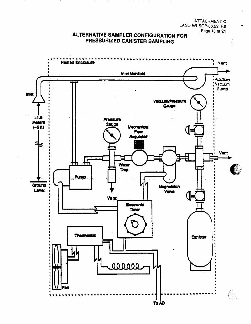
-1.1 Mellf'l (-1ft)
ATTACHMENT C LANL-EA-SOP-06.22, AO
ALTERNATIVE SAMPLER CONFIGURATION FOR PRESSURIZED CANISTER SAMPLING
Page 13 of 21
...... : .•..........••.••••..•..•..................... HatiCS lndcaJI"' , 'V tnt
fnfeit Manifold • I AuxiTll31"(
Vent ____ .._..,
n.ma r•
• • •• ••••••••••••••••••••••••••••••
: Vac:-.. 'l.;m • Pum~
• Vent
••••••••••••••••• ( ToAC

(
c . .
(
\
ATIACHMENT 0 LANL-ER-SOP-06.22, RO
Page 14 of 21
SCHEMATIC OF CALIBRATION SYSTEM AND MANIFOLD FOR: (a) ANALYTICAL SYSTEM CALIBRATION, (b) TESTING CANISTER SAMPLING SYSTEM AND, (c) PREPARING
CANISTER TRANSFER STANDARDS

ATTACHMENT E LANL·ER·SOP-06.22, RO
Page 15 of 21
CANISTER ANALYSIS UTILIZING GC-MS.SCAN-SIM ANALYTICAL SYSTEM WITH OPTIONAL FLAME IONIZATION DETECTOR WITH THE 6-PORT CHROMATOGRAPHIC VALVE IN THE SAMPLE DESORPTION MODE
(
(
ATTACHMENT F LANL-ER-SOP-06.22, RO
Page 16 of 21
CANISTER CLEANING AND CERTIFICATION PROCEDURES
A. All canisters must be clean and free of any contaminants before sample collection.
B. All canisters are leak tested by pressurizing them to approximately 206 kPa (30 psig) with zero air. (Note: The canister cleaning system in Attachment A can be used for this task.) The initial pressure is measured, the canister valve is closed, and the final pressure is checked after 24 hours. If leak tight, the pressure should not vary more than ±13.8 kPa (±2 psig) over the 24 hour period.
C. A canister cleaning system may be assembled as illustrated in Attachment A. Cryogen is added to both the vacuum pump and zero air supply traps. The cal1ister(s) are connected to the manifold. The vent shut-off valve and the canister valve(s) are opened to release any remaining pressure in the canister(s). The vacuum pump is started and the vent shut-off valve is then closed and the vacuum shut-off valve is opened. The canister(s) are evacuated to< 0.05 mm Hg (for at least one hour). (Note: On a daily basis or more often if necessary, the cryogenic traps should be purged with zero air to remove any trapped water from previous canister cleaning cycles.)
D. The vacuum and vacuum/pressure gauge shut-off valves are closed and the zero air shutoff valve is opened to pressurize the canister(s) with humid zero air to approximately 206 kPa (30 psig). 1(,~,.~~(9 g~ generator system is used, the flow rate may need to be limited to maintain the zero air quality.
E. The zero shut-off valve is closed and the canister(s) are allowed to vent down to atmospheric pressure through the vent shut-off valve. The vent shut-off valve is closed. Steps C through E are repeated two additional times for a total of three (3) evacuation/pressuration cycles for each set of canisters.
F. At the end of the evacuation/pressuration cycle, the canister is pressurized to 206 kPa (30 psig) with humid zero air. The canister is then analyzed by a GC-MS or GC-FID-ECD analytical system. Any canister that has not tested clean (compared to direct analysis of humidified zero air of less than 0.2 ppbv of targeted VOCs) should not be used. As a "blank• check of the canister(s) and cleanup procedure, the final humid zero air fill of 100% of the canisters is analyzed until the cleanup system and canisters are proven reliable (less than 0.2 ppbv of targets VOCs). The check can then be reduced to a lower percentage of canisters.
G. The canister is reattached to the cleaning manifold and is then reevacuated to <0.05 mm Hg and remains in this condition until used. The canister valve is closed. The canister is removed from the cleaning system and the canister connection is capped with a stainless steel fitting. The canister is now ready for collection of an air sample. An identification tag is attached to the neck of each canister for field notes and chain-of-custody purposes.
AITACHMENTG LANL-ER-SOP-06.22, RO
Page 17 of 21
SAMPLING SYSTEM CLEANING AND CERTIFICATION PROCEDURES
Cleaning Sampling System Components
A. Sample components are disassembled and cleaned before the sampler is assembled. Nonmetallic parts are rinsed with HPLC grade deionized water and dried in a vacuum oven at 50"C. Typically, stainless steel parts and fittings are cleaned by placing them in a beaker of methanol in an ultrasonic bath for 15 minutes. This procedure is repeated with hexane as the solvent.
B. The stainless steel parts are then rinseC: with HPLC grade deionized water and dried in a vacuum oven at 1 oo·c for 12 to 24 hours. ·
C. Once the sampler is assembled, the entire system is purged with humid zero air for 24 hours.
Humid Zero Air Certification - (see Section 6.1)
(Note: In the following sections, •certifir.:;.tion• is defined as evaluating the sampling system with humid zero air and humid calibration gases that pass through all active components of the sampling system. The system is •certified• if no significant additions or deletions [less than 0.2 ppbv of targeted co111pounds] have occurred when challenged with the test gas stream.)
A. The cleanliness of the sampling system is determined by testing the sampler with humid zero air without an evacuated gas cylinder, as follows.
B. The calibration system and manifold are assembled, as illustrated in Attachment G. The sampler (without an evacuated gas cylinder) is connected to the manifold and the zero air cylinder activated to generate a humid gas stream (2 Vmin) to the calibration manifold (see Attachment G [b]).
C. The humid zero gas stream passes through the calibration manifold, through the sampling system (without an evacuated canister) to a GC-FID-ECD analytical system at 75 cm3/min so that 40 cm3/min is pulled through the six-port valve and routed through the cryogenic
-trap (see EPA reference Compendium Method T0-14, Section 10.2.2.1) at the appropriate time while the extra sample is vented. (Note: The exit of the sampling system [without the canister] replaces the canister in Attachment H.) After the sample (400 ml) is preconcentrated on the trap, the trap is heated and the VOCs are thermally desorbed onto the head of the capillary column. Since the column is at -so·c, the VOCs are cryofocussed on the column. Then, the oven temperature (programmed) increases and the VOCs begin to elute and are detected by a GC-MS (see EPA reference Section 1 0.2) or the GC-FIDECD. The analytical system should not detect greater than 0.2 ppbv of targeted VOCs in

(
ATTACHMENT G, Continued LANL-ER-SOP-06.22, AO
Page 18 of 21
order for the sampling system to pass the humid zero air certification test. Chromatograms of a certified sampler and contaminated sampler are illustrated in Attachment J (a) and (b), respectively. If the sampler passes the humid zero air test, it is then tested with humid calibration gas standards containing selected VOCs at concentration levels expected in field sampling (e.g., 0.5 to 2 ppbv) as follows:
Sampler System Certification with Humid Calibration Gas Standards - (see Section 6.1)
A. Assemble the dynamic calibration system and manifold as illustrated in Attachment G.
B. Verify that the calibration system is clean {less than 0.2 ppbv of tergeted compounds) by sampling a humidified gas stream, without gas calibration standards, with a previously certified clean. canister (see EPA reference Section 12.1).
C. The assembled dynamic calibration system is certified clean if less than 0.2 ppbv of targeted compounds are found.
D. For generating the humidified calibration standards, the calibration gas cylinder(s) (see EPA reference Section 8.2} containing nominal concentrations of 10 ppmv in nitrogen of selected VOCs, are attached to the calibration system, as outlined in EPA reference Section
1: 1 0.2.3.1. The gas cylinders are opened and the gas mixtures are passed through 0 to 10 ,,; cm3/min certified mass flow controllers to generate ppb levels of calibration standards.
\c \,,\"·,','··'V''"··, I
E. After the appropriate· equilibrium period, attach the sampling system (containing a certified evacuated canister) to the manifold, as illustrated in Attachment G (a).
F. Sample the dynamic calibration gas stream with the sampling system according to EPA reference Section 9.2.1. (Note: To conserve generated calibration gas, bypass the canister sampling system manifold and attach the sampling system to the calibration gas stream at the inlet of the in-line filter of the sampling system so the flow will be less than 500 cm3/min.)
G. Concurrent with the sampling system operation, real-time monitoring of the calibration gas stream is accomplished by the on-line GC-MS or GC-multidetector analytical system (Attachment G [b]) to provide reference concentrations of generated VOCs.
H. At the end of the sampling period (normally same time period used for anticipated sampling), the sampling system canister is analyzed and compared to the reference GC-MS or GC-multidetector analytical system to determine if the concentration of the targeted VOCs was increased or decreased by the sampling system.
I. A recovery of between 90% and 110% is expected for all targeted VOCs.

ATTACHMENT H LANL-EA-SOP-06.22, RO
Page 19 of 21
CANISTER SAMPLING FIELD OAT A SHEET
Date:------LOS ALAMOS NATIONAL LABORATORY
ENVIRONMENTAL RESTORATION CANISTER SAMPUNG FIELD DATA SHEET
Sheet __ of __
Expected Sample Concentration Technical Area---- Operable Unit-----a HIGH (2. 1000 ppm a LOW (s 1000 ppm)
Site WorX Plan:--------------
Signature:-----------------
SAMPLING INFORMATION
r-m1 i ARSf SAIIIl.E ! ! ST1CKER HERE l : ... _ ............... ___ ,
. AFFIX . ! LAST SAMPlE ,
~----~--~~ ... !
Canister Leak Ched< Date: ----------
START
START
LOCAL TIME
PRESSURE (DSial
CANISTER PRESSURE
_sT_o_P_~--~-------~~IY~k-------~~--~~~--~ ~--
SAMPLING SYSTEM CERTIFICATION DATE: _____ 0_Yr>___,~A......'I'#--=------------
•17..d QUARTERLY RECERTIFICATION DATE: -"l.
LABORATORY INFORMATION:
DATE RECEIVED:---------
RECEIVED BY:-----------INITIAL PRESSURE: ________ _
FINAL PRESSURE:----------DILUTION FACTOR: ________ _
GC-FIO-ECD DATE:--------
GC-MSD-SCAN DATE:-------
GC-MSO-SIM DATE:---------
RESULTS: _____________________________ _
GC-FIO-ECO: ___________________________ _
GC-MSD-SCAN: __________________________ _
GC-MSD-SIM: ___________________________ _
a CHECK HERE IF CONTINUED OH BACK OF THIS SHEET (

DATA FORM COMPLETION
ATTACHMENT l LANL-ER-SOP-06.22, RO
Page 20 of 21
Use an indelible dark ink pen. Make an entry in each entry blank. For entry blanks for which no data are obtained, enter UNK for Unknown, NA for Not Applicable, NO for Not Done, etc. To change an entry, draw a single line through it, add the correct information above it, and date and initial the change. For all forms, complete the following information:
1. Technical Area (TA). Two-digit number indicating in which area the sampling is being done
2. Operable Unit (OU). Four-digit number indicating the operable unit in which the sampling is being done
3. Expected Sample Concentration. Value determined by field measurements. This value is critical for the Laboratory. Make every effort to make a determination.
4. Site Work Plan. The name of the plan and it's date of application.
5. Signature: A legible signature of the field team leader or his designate.
6. Canister Serial Number. The number that is stamped on the connector. This is not the sample number.
7. Temperature
Interior. The tern~!'!l:t!Jr~J(l the il")sulated enclosure Ambient. The temperature outside the insulated enclosure Maximum. The maximum temperature inside the box during sampling Minimum. The minimum temperature inside the box during sampling
8. Pressure. The starting pressure for subatmospheric/pressure will be negative. The ending pressure for subatmospheric should be negative and positive for pressure sampling
9. Sampling Times. Record the start and stop times and the elapsed time from the meter
1 0. Flow rates
Manifold Flow Rate. Flow rate for inlet flow manifold Canister Flow Rate. Flow rate downstream of the mass flowmeter Flow Controller readout. The value read directly from the Mass Flow Control Unit Zero reading. This is taken time mass flowmeter (Refer to Section 6.0E)
11. Sampling System Certification Date. The date when the system was initially certified
12. Quarterly Recertification Date. Sample equipment must be calibrated on a quarterly basis
13. Laboratory Information. Data filled out by the Laboratory

ATTACHMENTJ LANL-ER-SOP-06.22, RO
Page 21 of 21
EXAMPLE OF HUMID ZERO AIR TEST RESULTS FOR (a) A CLEAN SAMPLER AND (b) A CONTAMINATED SAMPLER
• T1MI_.
{a). Certified Sampler
Ttlla_,.
(b). Contaminated Sampler
(
(

(
(
Los Alamos National Laboratory No: LANL-ER-SOP-06.23 Rev:O Environmental Restoration Program
Standard Operating Procedure
~----~--------------------~----------------------------~
Prepared by
MEASUREMENT OF GAMMA-RAY FIELDS USING A SODIUM IODIDE DETECTOR
J3o/IANIC 1/.;m_ ~ /hL- Y/'7 .•. /'1 S (Print Name) ' ~.-:::..::: /( "' (Date) I
Quality Review by Jo..~e f VV· He. js-e~ ~,\tV: ~ (Print Name) <t§lgnature)
4/2.0/q-3 (Date)
Technical Review by
PM Approval
QPPL Approval
~ 01-LU HIY J.1 JJ (Print Name)<·'
4-)1-?'5 (Date)
A. e. No[?RIS awl! ~ ~ -Zb-~ (Print Name) (Signature) (Date)
Effective Date: ~ ~ 19, I 9 'f 3
i
TABLE OF CONTENTS
LANL-ER-SOP-06.23, RO Page 1 of 4
1.0 PURPOSE .............................................................................................................. 2
2.0 SCOPE .................................................................................................................... 2
3.0 DEFINITIONS ......................................................................................................... 2
4.0 BACKGROUND AND/OR CAUTIONS ............................................................... 2
5.0 EQUIPMENT .......................................................................................................... 3
6.0 PROCEDURE ......................................................................................................... 3
7.0 REFERENCES ....................................................................................................... 4
8.0 RECORDS .............................................................................................................. 4
9.0 A TI ACHMENTS .................................................................................................... 4
/
( '
1.0
LANL-ER-SOP-06.23, RO Page 2 of 4
Measurement of Gamma-Ray Fields Using A Sodium Iodide Detector
PURPOSE
This procedure provides instructions for making count-rate measurements of gamma-ray fields with a sodium iodide (Nal) detector.
2.0 SCOPE
This procedure includes activities required to conduct a radiation survey to quantitatively measure low-level gamma emitters.
3.0
2.1 Applicability
This procedure applies to site workers who will be conducting the field radiation survey.
2.2 Training
Site workers conducting the radiation survey will be trained health physicists or health physics technicians (or have equivalent education or experience).
DEFINITIONS
A. Gamma rays: highly penetrating forms of radiation. As they penetrate the body, gamma rays can damage living cells, and are therefore, considered an external hazard.
B. Radioactivity: the physical property, or capability, of certain elements to release particles or waves of energy. As radioactive elements disintegrate, they exhibit radioactivity by emitting gamma rays and other particles and radiation.
4.0 BACKGROUND AND/OR CAUTIONS
This radiation survey is used to quantitatively measure gamma rays from radionuclides in the area. It may be used to indicate contamination by gamma emitters after the entire area is surveyed and mapped to define radioactive hot spots or plumes. The Nal detector is used primarily to measure increases in background radiation and to locate and measure sources of radiation that cause the background readings to change. Note that elevated count-rate data must be carefully interpreted because uncontaminated areas can demonstrate high readings if they are hext to an area contaminated with gamma emitters.

5.0 EQUIPMENT
Equipment and supplies to be used are listed below.
LANL-ER-SOP-06.23, RO Page 3 of 4
Portable ratemeter/scaler and sodium iodide detector (1 inch by 1 inch)
0-cell batteries
Gamma check source
6.0 PROCEDURE
PRIOR TO MEASUREMENTS
A. Refer to the operator's manual for specific instructions on the operation of the Nal detector.
B. Inspect the equipment and connector cable (where appropriate) for obvious damage or a frayed or broken cable.
C. Check the battery condition and if the check indicates low battery power, replace the batteries.
D. Check the calibration sticker and ensure that the instrument has been calibrated within the Nal detector specific time frame (e.g., every 6 months for a -:~. Ludlum 12S Nal Detector).
E. Perform a source check and note the response of the detector .
GENERAL OPERATING PROCEPURE
A. To survey radiation levels in an area, walk slowly, listen for increases in audible response, and look for needle deflection indicating an increase in radiation levels. In generai; the instrument should be held approximately 3 feet above the ground (waist l~=wel). To determine the maximum radiation levels, vary the height and direction of the detector. When an increase is noted, hold the instrument at that point for at least 15 seconds (or as long as indicated in the operations manual for specific models) to obtain an accurate count rate.
B. To obtain a contact reading of an object or surface, place the instrument directly on the object or surface and hold for at least 15 seconds (or as long as indicated in the operations manual for specific models) to obtain an accurate count rate. If the object or surface is known or suspected to have loose contamination, exercise good radioactive contamination safety practices, and do not allow the instrument to come in contact with the surface.
. .• )

r
•. ~
LANL-ER-SOP-06.23, RO Page 4 of 4
C. When scanning an object with the instrument , scan at 1-2 inches per second (or as quickly as indicated in the operations manual for specific models).
D. Give particular attention to drain lines, piping, ductwork, pits, sumps, or any other likely places where radioactivity may be present.
E. Record all field survey point readings and other relevant data.
F. If necessary, ensure that all survey and sample locations are properly staked with a visible location identification.
G. At the end of field activities, ensure that all equipment is accounted for, decontaminated, and ready for shipment.
7.0 REFERENCES
A. The Ludlum 12S Radiac Training Guide. Prepared by Afftrex, LTD. Pittsburgh, PA.
B. Instruction Manual for the Ludlum 12S Sodium Iodide Detector. Ludlum Measurements, Inc. Sweetwater, IX.
8.0 RECORDS
All records generated as a result of this procedure will be submitted to the Record Processing Facility. These records include but are not limited to:
Daily Activity Log which will include all daily activities and any deviations from this procedure.
9.0 ATTACHMENTS
N/A

' Los Alamos National Laboratory No: LANL-ER-SOP-06.24 Rev: 0
Environmental Restoration Program Standard Operating Procedure
SAMPLE COLLECTION FROM SPLIT-SPOON SAMPLERS AND
SHELBY TUBE SAMPLERS
Prepared by Lifldtt. F /~1< (Print Name)
Quality Review by~ il-<r it>r- 1-/e'j S e._ an- h:- ¥ (Print Name) ( · nature)
Technical Review by
PM Approval
QPPL Approval
C, J. r;_{\c \ \)_ (Print Name)· ... ~ ·· ·. ···
A. E. HaKtrJS (Print Name)
(Signi(; e
~tv!/o-rL (Signature)
(Signature)
(Date)
(Date)
4-- r- )3 (Date)
t-.Jt- '13 (Date)
(Date)

TABLE OF CONTENTS
LANL-ER-SOP-06.24. RO PAGE 1 OF6
1.0 PURPOSE .............................................................................................................. 2
2.0 SCOPE .................................................................................................................... 2
2.1 Applicability ................................................................................................ 2
2.2 Training ...................................................................................................... 2
3.0 DEFINITIONS ......................................................................................................... 2
4.0 BACKGROUND AND/OR CAUTIONS ............................................................... 2
4.1 Introduction ................................................................................................. 2
4.2 Cautions ...................................................................................................... 3
5.0 EQUIPMENT .......................................................................................................... 4
6.0 PROCEDURE ......................................................................................................... 4
7.0 REFERENCES ....................................................................................................... 6
8.0 RECORDS .............................................................................................................. 6
4'
f

I ~·
LANL-ER-SOP-06.24. RO PAGE20F 6
SAMPLE COLLECTION FROM SPLIT-SPOON SAMPLERS AND SHELBY TUBE SAMPLERS
1.0 PURPOSE
This standard operating procedure (SOP) provides instructions that are to be followed in collecting soil and sediment samples from split-spoon samplers or Shelby Tube samplers.
2.0 SCOPE
3.0
2. 1 Applicability
This procedure is applicable for collection of soil and sediment samples from split-spoon samplers or Shelby Tube samplers for the Environmental Restoration Program.
2.2 Training
Field team members must document that they have read and understand this procedure, and all procedures in Section 1.0 (General Instructions) of the Laboratory's Environmental Restoration Standard Operating Procedures (SOPs).
DEFINITIONS
A. Shelby Tube: A single-piece metal tube of thin gauge which is forcefully driven into the soil or sediment at the bottom of a bore hole in order to collect an undisturbed subsurface soil or sediment sample.
B. Split-spoon Sampler: A multiple piece sampler which is threaded on to the end of a drill rod or hand auger and is forcefully driven into the soil or sediment at the bottom of a bore hole in order to collect an undisturbed subsurface soil or sediment sample.
4.0 BACKGROUND AND/OR CAUTIONS
4.1 Introduction
A split-spoon sampler is used to take subsurface soil or sediment samples by being forcefully driven into the soil or sediment at the bottom of a bore hole. Samples may be retrieved along the entire length of the bore hole to obtain an unbroken record of the subsurface layers, or samples may be retrieved at selected intervals. Continuous samples may also be taken from the surface down to a specified level or from a subsurface point downward.
LANL-ER-SOP-06.24. RO PAGE3 OF6
The split-spoon is threaded on to the end of the drill rod in place of the drill bit. The sampler is lowered on the drill rod to the bottom of the boring by heavy steel cable connected to the drilling mast. The sampler is forced into the soil by a drive weight which is dropped repeatedly onto the drive head located at the top of the drill rod. Weights up to 350 pounds are available, but the most commonly used weight for a 2-inch diameter sampler is a 140-pound weight. The weight is typically allowed to fall a distance of 30 inches. The sampler is driven into the sediment to a depth about 6 inches shorter than the length of the sampler itself. Split-spoon samplers are manufactured in 18- and 24-inch lengths with 2- to 3-inch outside diameters.
Occasionally bedrock or extremely compacted sediments are encountered which make further advance of the sampler extremely difficult or impossible without damage to the sample. This condition is known as "rt::fusal" and is defined as a "penetration of less than 1 foot for 100 blows" (a blow is the act of striking a drive rod with a drive weight). Six inches for 50 blows is also commonly recognized as refusal. Upon refusal, the bore hole is to be either abandoned or the sampler removed and replaced by a drill bit.
Split-spoon sampling may also be performed with the hand auger. The splitspoon is threaded on to the end of the hand driven drill rod in place of the auger/bit. The split-spoon is advanced into the bore hole by manually turning the hand auger. In all other respects, hand auger split-spoon sampling is identical to hydraulically driven split-spoon sampling.
A similar type of sampling apparatus is the "Shelby" tube. While the split-spoon is a multiple piece sampler, the Shelby Tube is a single-piece metal tube of thinner gauge than the split-spoon. Like the split-spoon, soil is forced into the Shelby Tube and stored inside. However because the Shelby Tube is typically advanced hydraulically, it allows the capture of a relatively undisturbed sample. The Shelby Tube requires much less effort to push into the soil due to its thinner walls and sharp cutting edge. Care must be taken not to compress the soil sample by forcing the tube deeper than its own length.
4. 2 Cautions
This procedure is limited to the activities of collecting soil and sediment samples for field monitoring and laboratory analysis for concentrations of hazardous and radioactive constituents or for soil/sediment physical characteristics. This SOP does not address the drilling activities, removal of time sensitive geologic analytical samples, core documentation, lithologic description, packaging of core material or temporary storage of borehole materials at a drill site Sample Management Trailer.
(

' ' .,,
5.0 EQUIPMENT
LANL-ER-SOP-06.24. RO PAGE40F 6
Equipment needed for sample collection using split-spoon and Shelby Tube samplers is as follows:
__ 2.5-inch, 2.0-inch, or 1.5-inch internal diameter (10) split-spoon drive sampler
__ 2.5-inch, 2.0-inch, or 1.5-inch brass liners and sealing materials (plastic end caps, Teflon seals, non-adhesive silicon or Teflon tape, ziplock bags)
Shelby tube sampler
Work table surface --Knife/blade
Sampling tools
__ Buckets
High purity laboratory detergent, such as Alconox
__ 0.1 N nitric acid (if necessary)
Deionized Water
__ Chain of Custody/Request for Analysis forms
6.0 PROCEDURE
A. Coordinate the sampling effort with the Health and Environmental Chemistry Group (EM-9) and Sample Coordination Facility (SCF). They will give guidance regarding sample containers and preservation.
B. Label all bottles and complete documentation (SOP-01.02, Sample Containers and Preservation, and SOP-01 .04, Sample Control and Field Documentation). Fill out all information except sampler's name/initials and the actual date and time.
C. Assemble the sampler and ensure that all sampling equipment has been properly decontaminated. If decontamination cannot be guaranteed, decontaminate the sampler following guidance in step M of this procedure.
D. Note exact location of the hole where the sample has been collected in the field notebook. If not tied in to a surveyed grid system or some other well documented system, measure the distances and direction from stationary

LANL-ER-SOP-06.24. RO PAGES OF6
landmarks. If possible, photograph the location. As appropriate, spray paint or wooden stakes may also be used to mark the location.
E. Collect the split-spoon sampler or Shelby Tube sampler from the driller and place it on a secure bench or rack. If a Shelby Tube sampler is used, submit the entire tube to the laboratory.
F. Separate the split-spoon sampler tube (a flat-blade screwdriver is useful), exposing either the sample or, if used, brass liners. Run a knife between the liners to separate the tube.
G. If volatile organic compound (VOC) analysis is required, immediately seal the cut ends of the split-spoon sampler with Teflon film. The field team member will log the borehole material in the field notebook at this time. The field team member will also record in the field notebook the borehole identification number, run number, depth interval, and percent recovery (as appropriate).
H. If no liner is used, the sample may be collected from the open split-spoon sampler using a decontaminated stainless steel spoon (or other appropriate sampling tool). The sample may be collected as a "composite" of several discrete points within the sampler or as a "grab" sample from one discrete point within the sampler. The sample collection strategy and rationale must be discussed and documented in the field notebook and/or daily logs.
(
I. If the samples are being analyzed for VOCs, collect the VOC fraction first. 1/j· .. ·· VOC sample containers should be tightly packed, using a decontaminated ~ stainless steel spoon (or other appropriate sampling tool), leaving no airspace in the sample container.
J. For composite samples (where VOCs are not an analytical parameter) collect small amounts of soil or sediment from several discrete points within the split-spoon sampler using a decontaminated stainless steel spoon (or other appropriate sampling tool), and place the soil or sediment in a decontaminated stainless steel or plastic bucket or a plastic ziplock bag. Mix the soil or sediment several times until the material is well mixed and homogeneous. Sampling points for the composite sample may be selected randomly, at regular intervals, or based on visual inspection. Alternatively, place the entire core into a decontaminated stainless steel or plastic bucket and mix until the sample is homogenized. The sample collection strategy and rationale must be discussed and documented in the field notebook and/or daily logs.
K. Decontaminate the outside of the sample containers, bag the samples in a ziplock bag, and place the samples in a cooler at the sampling site. The cooler should contain ice as specified by the site-specific sample plan.
L. Field duplicates may be collected either by compositing the soil in a decontaminated stainless steel or plastic bucket (a composited field duplicate) or sampling from a close adjacent location (a collocated field duplicate). Collocated ( field duplicates are to be collected from adjacent liners. Follow the site-specific \. ·

LANL-ER-SOP-06.24. RO PAGE60F6
sample plan and document the duplicate collection process in the field notebook and/or daily logs.
M. Following each sampling event, wash the split-spoon sampler with high purity laboratory detergent and double rinse the components with deionized water, methanol, 0.1 N nitric acid, and/or other rinse solution as appropriate or as specified in the site-specific sampling plan. Brass liners and Shelby Tube samplers should be cleaned in the laboratory prior to use and rinsed in the field with deionized water prior to use.
7.0 REFERENCES
LANL-ER-QPP, Quality Program Plan for Environmental Restoration Activities LANL-ER-SOPs in Section 1.0, General Instructions
8.0 RECORDS
All records generated as a result of this procedure will be submitted to the Record Processing Facility. These records include but are not limited to the Daily Activity Log which will include all daily activities and any deviations from this procedure.

Los Alamos National Laboratory No: LANL-ER-SOP-06.25 Rev: 0 Environmental Restoration Program
Standard Operating Procedure
TOTAL SUSPENDED PARTICULATE AIR SAMPLING
Prepared by
Quality Review by I YAN fo/11cllwc (Print Name) -3.!'- (SiQnatUre}
Technical , I.J: 1l ~. i1vl~ F!tt t '-/ i
Review by .' .,
--r- ' i
(Print Name) {Signature) 7 \
7
PM Approval :{?be r r W t/ocJ~ £-14-wt/J (Print Name) (Signature)
QPPL Approval .'? /.} ~ ~ ... -· a. G) ..... ~~: ~ C' ~ e.E.ngmS·C~u (Print Name) (Signature)
Effective Date: j \..vY"\..L ~ c:; • \ '1q 3
(Date)
·~ ~ ... - - I;' t./ ) !
(Date)
5/:-'f/93 (Dater '
lt;r .z~ (f1"3 (D t

TABLE OF CONTENTS
LANL-ER-SOP-06.25, RO Page 1 of 5
1.0 PURPOSE .............................................................................................................. 2
2.0 SCOPE .................................................................................................................... 2
2.1 APPLICABILITY ......................................................................................... 2
2.2 TRAINING ................................................................................................... 2
3.0 DEFINITIONS ......................................................................................................... 2
4.0 BACKGROUND AND/OR CAUTIONS ............................................................... 2
5.0 EQUIPMENT .......................................................................................................... 3
6.0 PROCEDURE ......................................................................................................... 3
7.0 REFERENCES ....................................................................................................... 5
8.0 RECORDS .............................................................................................................. S
9.0 ATTACHMENTS .................................................................................................... 5

)
LANL-ER-SOP-06.25, RO Page 2 of 5
Total Suspended Particulate Air Sampling
1.0 PURPOSE
This procedure describes the methods for the determination of suspended particulate matter in the atmosphere using a high-volume air sampler.
2.0 SCOPE
2.1 APPLICABILITY
This procedure is applicable for air sampling using a high-volume air sampler.
2.2 TRAINING
All site workers who operate a high-volume air sampler should document that they have read and do understand this procedure, the operation manual for the high-volume sampler, and the procedures in Section 1.0, General Instructions, of the Los Alamos National Laboratory's Environmental Restoration Standard Operating Procedures (LANL-ERSOPs).
3.0 DEFINITIONS
N/A
4.0 BACKGROUND AND/OR CAUTIONS
This method provides a measurement of the mass concentration of total suspended particulate matter (TSP) in ambient air for determining compliance with the primary and secondary national ambient air quality standards for particulate matter. The measurement process is nondestructive, and the size of the sample collected is usually adequate for subsequent chemical analysis.
An air sampler properly located at the measurement site draws a measured quantity of ambient air into a covered housing and through a filter during a 24 hour or other appropriate sampling period. The sampler flow rate and the geometry of the shelter favor the collection of particles up to 25-50 microns (J.lm) (aerodynamic diameter), depending on wind speed and direction. The filters used are specified to have a minimum collection efficiency of 99 percent as measured by the American Society for Testing and Materials (ASTM)-2986 method for particles of 0.3 J.lm diameter.
The filter is weighed (after moisture equilibration) before and after use to determine the net weight (mass) gain. The total volume of air sampled, corrected to the Environmental Protection Agency (EPA) standard conditions [25·c, 760 millimeters mercury (mm Hg)], is determined from the measured flow rate and the sampling time. The concentration of TSP matter in the ambient air

LANL-ER-SOP-06.25, RO Page 3 of 5
is computed as the mass of collected particles divided by the volume of air sampled, corrected to standard conditions, and is expressed in micrograms per standard cubic meter (!-Lg/std m3). For samples collected at temperatures and pressures significantly different than standard conditions, these corrected concentrations may differ substantially from actual concentrations (micrograms per actual cubic meter), particularly at high elevations. The actual particulate matter concentration should be calculated using the actual temperature and pressure during the sampling period.
The approximate concentration range of the method is 2 to 750 1-1g/std m3. The upper limit is determined by the point at which the sampler can no longer maintain the specified flow rate due to the increased pressure drop of the loaded particle size distribution, moisture content of the collected particles, and variability from filter to filter, among other things. The lower limit is determined by the sensitivity of the balance and by inherent sources of error.
At wind speeds between 1.3 and 4.5 meters per second (3 and 1 0 miles per hour}, the high-volume air sampler has been found to collect particles up to 25 to 50 11m, depending on wind speed and direction. For filters that meet EPA specifications as described in 40 CFR 50, Appendix 8, there is effectively no lower limit on the particle size collected.
5.0 EQUIPMENT
The equipment needed for this procedure is listed below.
High-volume air sampler Filters Cassette filter holder Flow rate measurement devices
Flow indicator (e.g., orifice, rotameter) Pressure indicator (e.g., manometer)
Thermometer Barometer Timing/control device Flow rate transfer standard Manila and glassine envelopes Electrical"generator, if necessary Unleaded gasoline for generator, if necessary Extension cords
6.0 PROCEDURE
1. Ensure that the high-volume air sampler has been calibrated within the past six months. If it has not been calibrated within the past six months, then calibrate the instrument according to the operations manual.
)

LANL-ER-SOP-06.25, RO Page 4 of 5
2. Number each filter with an unique identification number and ensure that the filters have been weighed (after moisture equilibration) at the laboratory which will analyze the filters.
3. Backlight each filter and inspect for pinholes, particles, and other imperfections; a filter with visible imperfections must not be used.
4. Read the operator's manual for the specific high-volume air sampler to be used.
5. Place sampler motor/blower unit and filter holder in the servicing position by raising both of them up until the filter holder is above the top level of the shelter. Then rotate the unit one-quarter turn, clockwise or counterclockwise (depending on placement), so that the filter holder hangs in the rectangular hole in the sampler support pan.
6. Remove faceplate part of the filter holder by loosening the four wing nuts, allowing the swing bolts to swing down out of the way.
7. Carefully center a numbered 8" x 1 0" filter, rougher side up, on the supporting screen of the filter holder. Properly align the filter on the screen so that when the faceplate is in position, the gasket will form an airtight seal on the outer edges of the filter.
8. Secure the filter with the faceplate, tighten the four swing bolts with sufficient pressure to avoid air leakage, lower the filter holder and sampler blower/motor unit to its normal operating position, and close the shelter.
9. Plug the high-volume air sampler into an outlet or a gasoline operated generator. If a generator is used, ensure that it is placed downwind of the highvolume air sampler.
10. Run motor/blower unit for 5 minutes to allow it to warm up.
11. Record the flow rate for the sampler using the rotameter.
12. Set the timer to start and stop the sampler for the specified time period. Record the start and stop times.
13. After the sampling period, record the flow rate, again using the rotameter.
14. Carefully remove the exposed filter from the supporting screen by holding it gently at the ends (not at the corners). Fold the filter lengthwise so that sample touches sample.
15. Place filter in a glassine or similar folder.

LANL-ER-SOP-06.25, FW Page 5 of 5
16. Record all pertinent field information on the Daily Activity Log. For exam;Jie, all weather conditions (e.g., barometric pressure and temperature) and ' -\ instrument readings should be noted.
7.0 REFERENCES
40 CFR Part 50, Appendix B
ASTM Standard 2986, "Filter Collection as Measured by the DOP Test", American Society for Testing and Materials, Philadelphia, PA, 19103.
8.0 RECORDS
The Operable Unit Project Leader is responsible for transfer of the records to the ER Record Processing Facility (MS M707) in accordance with procedures for LANL ER Records Management (LANL-ER-AP-02.1 ). The records which will be generated include but are not limited to the following:
Daily Activity Log which will include all daily activities and any deviations from this procedure.
9.0 ATTACHMENTS
N/A
,,, ~
/
.)

Los Alamos National Laboratory No: LANL-ER-SOP-6.28 Rev:O Environmental Restoration Program
Standard Operating Procedure
CHIP SAMPLING OF POROUS SURFACES
Prepared by ~Do~U.lro~th.!.J,.y.J..IH¥.11oali.Uird~~..--__ ,_,/_ • _-:-zf ~ B;/& d$ (Print Name) ~ (~te) 7
Quality Review by Charlie Wilson (Print Name) (Signature)
Technical Review by
PM Approval
l QPPl Approval l '
John Smith (Print Name)
Jorg Jansen (Print Name)
Lany$Qula rx~ -(P...,rint.....,....,.Na....,me.._,) m.----'~ ZJ
Effective Date:
(Date)
(Dae)

LANL-ER-SOP-6.28, RO Page 1 of 5
CHIP SAMPLING OF POROUS SURFACES (
Contents
1.0 PURPOSE .............................................................................................................. 2
2.0 SCOPE ................................................................................................................... 2 2.1 Applicability ............................................................................................... 2 2.2 Training ................................................................... .-.................................. 2
3.0 DEFINITIONS ........................................................................................................ 2
4.0 BACKGROUND AND/OR CAUTIONS .............................................................. 2
5.0 EQUIPMENT .......................................................................................................... 2
6.0 PROCEDURE ........................................................................................................ 3
7.0 REFERENCES ...................................................................................................... 4
8.0 RECORDS ............................................................................................................ 4
9.0 ATTACHMENTS ................................................................................................... 4 e . '

1.0 PURPOSE
LANL-ER-SOP-6.28, RO Page 2 of 5
CHIP SAMPLING OF POROUS SURFACES
This procedure describes a methodology for collecting chip samples representative of porous surfaces, and the selection of equipment and materials to be used in the process.
2.0 SCOPE
3.0
2.1 Applicability
This procedure applies to personnel responsible for obtaining chip samples of porous surfaces for the Environmental Restoration (ER) Program. Porous surface sampling techniques are used for any porous object considered too large for collection as a discreet sample, or for cases where surficial contamination rather than contamination of the bulk material is of interest. Examples include intact structures such as a roadbed or wall, chunks of debris too large for transport, boulders or bedrock surfaces, and surfaces of functioning structures.
2:2 Training
The field team leader and the field team members shall be familiar with the objectives of chip sampling of porous surfaces and shall document that they have read and understood this procedure.
DEFINITIONS
Porous surface: in this context, a surface capable of allowing the passage of liquid through pores or small crevices. Examples of porous materials applicable to the ER Program include asphalt, concrete, wood, brick, unglazed clay pipe, and tuff.
4.0 BACKGROUND AND/OR CAUTIONS
The chipping process may create flying particles that could cause physical harm, particularly to the eyes.
5.0 EQUIPMENT
The equipment required to implement this procedure is listed in Attachment A.

LANL-ER-SOP-6~28. RO Page3 of 51
6.0 PROCEDURE
A. Identify the types of analyses to be conducted on the samples. Coordinate the sampling effort with the Sample Coordination Facility (SCF). The SCF will give guidance regarding sample containers, preservation, and shipment to the SCF.
I I'
B. Gather and decontaminate the necessary supplies and equipment in accordance with LANL-ER-SOP 01.08, Field Decontamination of Drilling and Sampling Equipment.
C. Assemble the tools and supplies and put on personal protective equipmen~ including goggles and work gloves.
D. Perform any in situ screening required by applicable work plans or health and! safety plans. Remove undesirable surface materials from the sampling location- byt brushing or wiping, as appropriate. Using a chisel, drill, hole saw, or similar tool,. collect a minimum of 100 grams of sample to a depth of 2 centimeters, or to an alternate depth specified in applicable planning documents. The sampled surface area and sampling depth should be recorded in the field Sample Collection Log. Non-porous inclusions, such as stones, glass, or metal, imbedded in the porous material, should be removed from the sample. The collected chips may be of any convenient size unless otherwise specified in applicable planning documents.
E. Transfer the sample to an appropriate sample container. Consult the SCF and LANL-ER-SOP 01.02, Sample Containers and Preservation, Attachment 0, for guidance regarding the amount (given in ml) of sample, the type of sample container, holding time; and· preservation techniques to be used for each analysis to) be conducted.
F. Complete Sample Collection Logs, Master Collection logs, and Chain of Custody Forms; label sample containers and complete documentation in accordance with LANL-ER-SOP 01.04, Sample Control and Field Documentation.
G. Clearly mark the sampled surfaces with paint or other indelible medium. The mark should include the site identification number. Document the site with photographs•. if appropriate.
H. Decontaminate the equipment, if intended for immediate reuse, prior to collecting. the next sample. Pack the samples for shipping to the SCF. Handle sampling wastes, excess sample materials, disposable items, and decontamination fluids following LANL-ER-AP-05.3, Management of Resource Conservation and Recovery Act facility investigations (RFI)-Generated Waste.
I. Upon completing sampling, pack equipment for cleaning and return equipment and supplies to their proper storage locations.
(. .

7.0 REFERENCES .
LANL-ER-SOP-01.01, General Instructions for Field Investigations. LANL-ER-SOP-01.02, Sample Containers and Preservation
LANL-ER-SOP-6.28, RO Page 4 of 5
LANL-ER-SOP-01.04, Sample Control and Field Documentation LANL-ER-SOP-01.08, Field Decontamination of Drilling and Sampling Equipment. LANL-ER-AP-05.3, Management of RFI-Generated Waste.
8.0 RECORDS
Completed Sample Collection Log Completed Location Information Form Completed Master Collection Log Completed Chain of Custody/Request for Analysis Form Completed Daily Activity Log, including any deviations or other pertinent information.
The person performing chip sampling is responsible for completing these logs and forms in accordance with LANL-ER-SOP-1.04, Sample Control and Field Documentation. The person performing chip sampling is also responsible for transferring the records generated under this procedures to the Environmental Records Processing Facility (RPF) in accordance with LANL-ER-AP-02. 1, Procedure for LANL ER Records Management.
9.0 ATTACHMENTS
Attachment A- Equipment and Supplies Checklist for Chip Sampling of Porous Surfaces

LANL-ER-SOP-6.2S: RO Page 5 of, ff.
EQUIPMENT AND SUPPLIES CHECKLIST FOR CHIP SAMPLING OF POROUS SURFACES (
Protective equipment _Safety glasses _Sturdy work boots _Work gloves
Sample preparation equipment _Alcon ox _Blue ice or equivalent _Camera and film _Chern wipes _Cleaning wipes _Disposable laboratory gloves _Paint or other indelible medium to identify sample location _Sample containers and preservatives _Storage containers for decontamination solutions
Sample collection and decontamination equipment _Brushes (galvanized, stainless steel, or plastic) _Brushes (long handle, scrub, or wire) _Drive hammer (3 to 10 lbs) _Wash tub or plastic bucket _Garden pressure or squeeze bottle sprayer _Plastic sheet _Stainless steel chisel _Stainless steel drill _Stainless steel hole saw _Tape measure _Trash bags
Paperwork _Borehole log (soil) form _Chain-of-Custody/Request-for-Analysis Form _Custody seals _Daily activity logs _Sample collection log _Sample labels _Unique sample identification number stickers
Note: Not all equipment is expected to be needed at every site.

) Los Alamos National Laboratory
Environmental Restoration Program Standard Operating Procedure
No: LANL-ER-SOP-10.04
MCA-465/FIDLER INSTRUMENT SYSTEM
Prepared by
Quality Review by \1u12-~\u<r;/ Q2~ (Print Name) (Signature)
Technical Review by
PM Approval
QPPL Approval
41+~ (Signature)
~---~"~-~---=c.e..~l9_.-=..~..:::..=.u~M (2{&{/ ~ (Print Name) (Signature)
Effective Date: _q...=....L_)_,_l=---~-L-!9Joo3L.-_
Rev:O
.-./.., /7-; (5i' ·- .• ,' ~· e:·.
(Date)
(Date)
;;4«1-
,1;4ff3 (Da e)
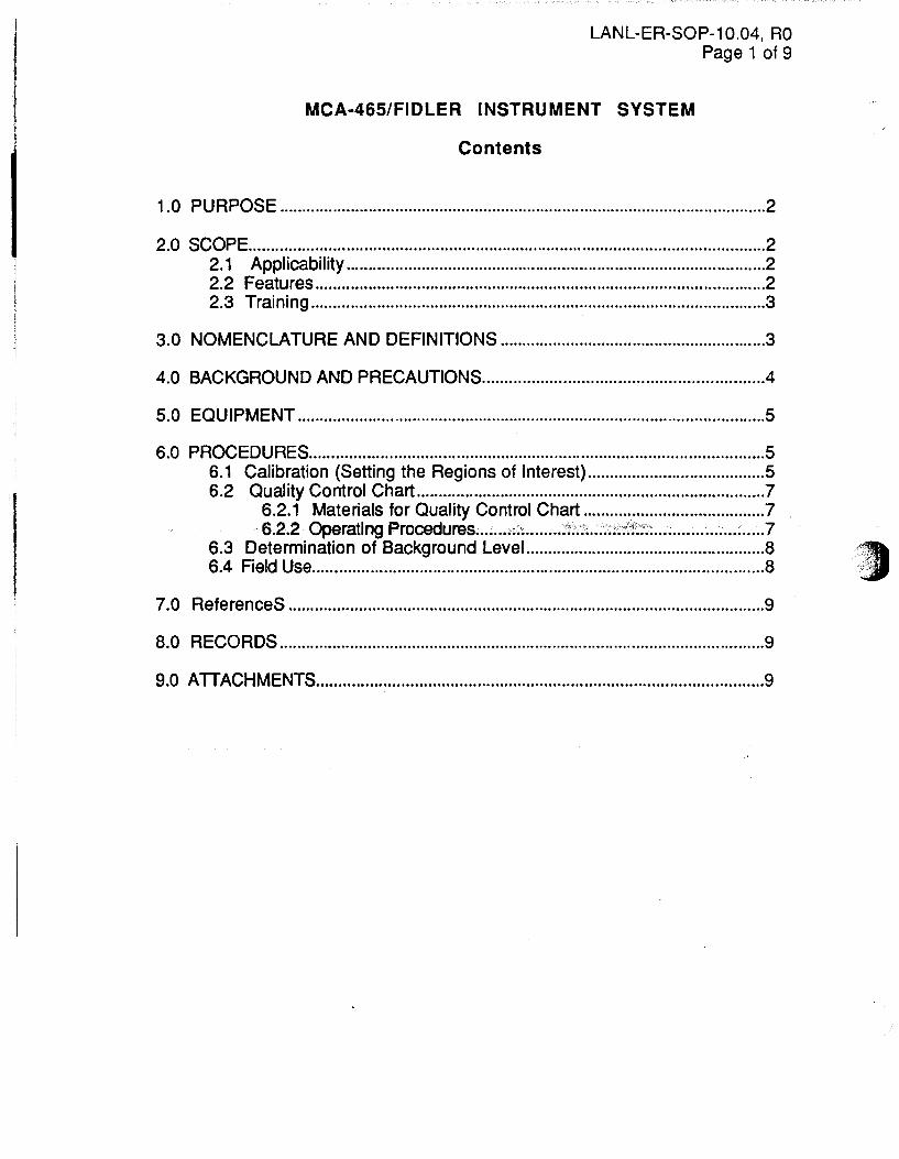
LANL-ER-SOP-1 0.04, RO Page 1 of 9
MCA-465/FIDLER INSTRUMENT SYSTEM
Contents
1.0 PURPOSE .............................................................................................................. 2
2.0 SCOPE .................................................................................................................... 2 2.1 Applicability ............................................................................................... 2 2.2 Features ...................................................................................................... 2 2.3 Training ....................................................................................................... 3
3.0 NOMENCLATURE AND DEFINITIONS ............................................................ 3
4.0 BACKGROUND AND PRECAUTIONS .............................................................. 4
5.0 EQUIPMENT .......................................................................................................... 5
6.0 PROCEDURES ...................................................................................................... 5 6.1 Calibration (Setting the Regions of Interest) ........................................ 5 6.2 Quality Control Chart ............................................................................... 7
6.2.1 Materials for Quality Control Chart ......................................... 7 6.2.2 Operating Procedures ........ ;~' ......... :;':';~~ ............. : ........................ ?
6.3 Determination of Background Level.. .................................................... 8 6.4 Field Use ..................................................................................................... 8
7.0 ReferenceS ............................................................................................................ 9
8.0 RECORDS .............................................................................................................. 9
9.0 ATIACHMENTS .................................................................................................... 9

LANL-ER-SOP-1 0.04, RO Page 2 of 9
J MCA-465/FIDLER INSTRUMENT SYSTEM
) /
1.0 PURPOSE
The following procedures outline the methods involved in the use of Environmental Protection Group's (EM-8's) Multichannel Analyzer (MCA)-465/Field Instrument for Detecting Low Energy Radiations (FIDLER) instrument system (TSA systems, 1992 a, b).
Specific procedures are given for: 1) Calibration of an Energy Spectrum and setting Regions of Interest; 2) Quality Control Checks; and 3) Field Use.
2.0 SCOPE
Adequate controls shall be established to ensure that only correct and acceptable field measurements will be collected with the FIDLER in support of Environmental Management (EM) operations performed for the Department of Energy.
2.1 Applicability
This instrument is used in soil radiological surveys .. conducted by the Waste Site Studies (WSS) section of EM-8 at Los Alamos National Laboratory (the Laboratory). The WSS section provides support to the Environmental Surveillance Program, to the Environmental Restoration Program investigations of potential release sites (PASs), and to the decommissioning and decontamination actions at the Laboratory.
Because the Laboratory routinely characterizes, handles and disposes of soils contaminated with alpha and beta emitting radionuclides (accompanied by gamma and x-ray emanations) the need for a detector that can field monitor soils with potential radioactive contamination is required.
The FIDLER detector is a scintillation detector that, when associated with a MCA, has the ability to measure low energy gamma and x-ray energies that accompany alpha and/or beta decay.
2.2 Features
Features available with this instrument are:
• 256 channel MCA.
• 4 energy spectrum Regions of Interest (ROI) are available.
• 14 memory locations for storing collected spectra are available.

LANL-ER-SOP-10.04, RO Page 3 of 9
• RS-232 connector and associated software package to allow for memory transfer to Personal Computer (PC) and PC Set-Up.
• Internal 1" x 2" Nal detector for measuring external penetrating background radiation.
2.3 Training
Personnel using this instrument will have been informed of the hazards associated with measuring radioactivity on soils. Both HAZWOPER and Radiation Worker training will be required of personnel using this instrument. Training will be the responsibility of WSS management. The calibration procedure will be conducted only by WSS management or other WSS trained personnel. Training for Quality Control, determination of detection limits, and field use will be required for all users of the FIDLER. Training documentation includes: 1) list of individuals authorized to use the system, 2) date of completed training, 3) Signature sheet indicating review of this standard operating procedure, and 4) Signature sheet indicating completion of in-the-field training and use of the instrument.
3.0 NOMENCLATURE AND DEFINITIONS
Nomenclature
For operating the MCA electronics package as outlined in Section 6.0, the nomenclature used is described below:
• Words in capital italics refer to the menus available on the MCA readout.
• Underlined words refer to options available under the given menu.
• Words in double quotes refer to information that is displayed in a particular option.
• Words enclosed in arrows, e.g., <ENTER> refer to keys on the MCA.
In addition:
• Options are selected using the up and down arrows.
• Option menus are selected by using the right arrow.
• Parameters are stored using the <ENTER> key.

LANL-ER-SOP-10.04, RO Page 4 of 9
. ) Definitions
BICBON FIDLER- a thin Nal crystal detector assembly that is sensitive to the low energy gamma and x-rays emitted by such long-lived alpha emitting radionuclides as 238Pu, 239Pu, 240pu and 241Am.
MultiChannel Analyzer (MCA)- a system that collects amplified output signals from a detector and sorts them into the appropriate channels based on the energy of the incident radiation.
Na! (Sodium Iodide) - a hygroscopic, inorganic crystal which emits UV photons (scintillates) as a result of a gamma or x-ray depositing energy in the crystal via a Photoelectric, Compton, or Pair Production interaction. The type of interaction resulting is dependent upon the energy of the incident emanation and the associated cross-section probability for Nal at that energy.
Region of Interest (ROI)- this is the region around a Total Absorption Peak (TAP) of interest.
4.0 BACKGROUND AND PRECAUTIONS
1. The Photomultiplier Tube (PMT) operates at highvoltage. Thus, care should be taken when connecting the signal cable'to the output and input on the detector.
2. Changes in temperature cause gain shifts with the PMT, thus PMTs are temperature sensitive and rapid temperature changes can damage the Nal crystal. Always allow the FIDLER to warm up or cool down at a rate not exceeding 1 ooc (18°F) per hour. Sufficient warm-up time is needed before use. Ten minutes should be an adequate warm up time for this instrument.
3. Care must be taken to preclude any damage to the exposed beryllium window of the detector.
4. Personnel using this equipment at PASs must be informed of the potential radiological hazards that may be encountered during field measurements. Personnel must have received either 24 hour or 40 hour HAZWOPEB, and either Radiation Worker I or II training to use this instrument in the field.
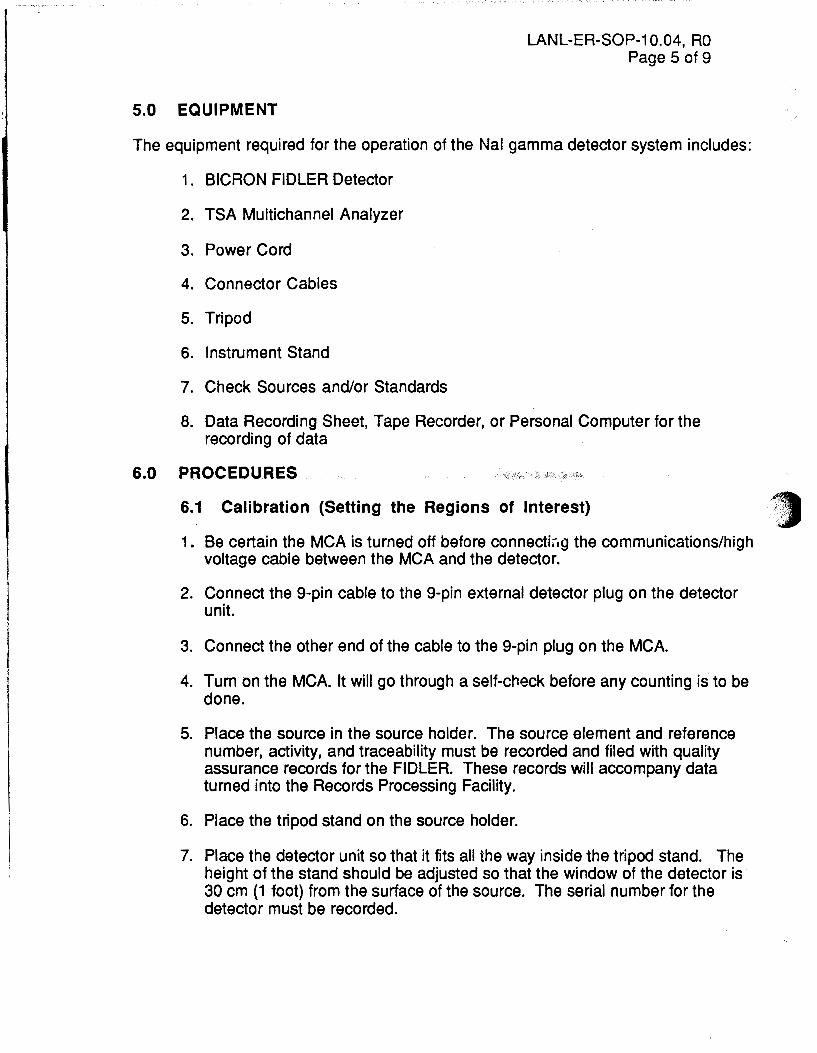
5.0 EQUIPMENT
LANL-ER-SOP-1 0.04, RO Page 5 of 9
The equipment required for the operation of the Nal gamma detector system includes:
1. BICRON FIDLER Detector
2. TSA Multichannel Analyzer
3. Power Cord
4. Connector Cables
5. Tripod
6. Instrument Stand
7. Check Sources and/or Standards
8. Data Recording Sheet, Tape Recorder, or Personal Computer for the recording of data
6.0 PROCEDURES
6.1 Calibration (Setting the Regions of Interest)
1. Be certain the MCA is turned off before connect!;-.g the communications/high voltage cable between the MCA and the detector.
2. Connect the 9-pin cable to the 9-pin external detector plug on the detector unit.
3. Connect the other end of the cable to the 9-pin plug on the MCA.
4. Turn on the MCA. It will go through a self-check before any counting is to be done.
5. Place the source in the source holder. The source element and reference number, activity, and traceability must be recorded and filed with quality assurance records for the FIDLER. These records will accompany data turned into the Records Processing Facility.
6. Place the tripod stand on the source holder.
7. Place the detector unit so that it fits all the way inside the tripod stand. The height of the stand should be adjusted so that the window of the detector is 30 em (1 foot) from the surface of the source. The serial number for the detector must be recorded.

h' , ~ ,· , :\ .. ::r:)
LANL-ER-SOP-1 0.04, RO Page 6 of 9
8. To calibrate the MCA so that the 100 keV energy corresponds to channel number 255, first determine the number of keV per channel using the following:
9.
10.
11.
1:.
13.
14.
15.
16.
17.
18.
19.
1 00 keV = 100 keV = 0.392 keV # of channels 255 channel
With this information, the correct channel number for the energy of a check source can now be calculated. All reference information for the check source must be recorded. For example, using 241Am as a check source, and measuring the 59.4 keV x-ray emitted, the channel number for this energy is calculated as follows:
59.4 keV • channel # = channel # 152 0.392
For this particular Total Absorption Peak, move the cursor on the MCA readout so that it is positioned at channel number 152.
Hit <mode> to get into the MODE menu. Choose the SET-UP mode using the cursor and arrow keys.
Select the PARAMETERS option by moving the cursor to this option, and pressing the right arrow key.
In the PARAMETERS menu, use the arrow keys to select a Live measurement time of "200" (count time of 200 seconds).
In the PARAMETERS menu, toggle the Time Mode option so that "Live" is displayed.
After the necessary parameters have been set, hit the <ENTER> key to store them in the unit. Exit the PARAMETERS menu.
From the 5ET-UP menu select the CALIBRATE option. The MCA will automatically begin to count the source.
Use the arrow keys to move the 59.4 keV peak until it is centered over or under the cursor.
Once the peak is centered, hit the <ENT> key to store the calibration factor in the unit.
While still in the SET-UP menu, move the cursor to select the ROI set-up option.
The Lo energy and Hi energy ends of the ROis are set to the Full Width Half Maximum (FWHM) on either side of the peak of interest by using the

LANL-ER-SOP-1 0.04, RO Page 7 of 9
arrow keys, and hitting <ENTER>. The mode key allows you to set other -~ ROis once one has been established.
20. Select "Lo I" to be the channel number on the left (lower energy) end of the first peak which contains one-half the maximum number of counts in that channel for that total absorption peak of interest. Likewise, select "Hi I" to be the channel number on the right (upper energy) end at the FWHM for that total absorption peak. Record the number of the "lo" and "hi" channels.
Note: If no one channel is exactly at the FWHM, use the channel with the closest number of counts to, but lower than, the FWHM as a bracketing channel.
21 . For the second total absorption peak and ROI select "Lo II" and "Hi II" using the same criterion that was used to select "Lo I" and "Hi I." Record the numbers of the "Lo" and "Hi" channels.
22. Be sure to hit <ENTER> before exiting the ROI set-up menu.
23. The MCA and FIDLER probe are now energy calibrated.
6.2 Quality Control Chart
The daily count rate from an 241Am check source is to be plotted on a running quality control chart. The quality control source check is to be done each day the instrument is used in the field. All reference information on the check source is to be recorded along with the~.QC data collected on a daily basis.
This chart tracks detector response to a known source as a function of calendar days. It can be used to establish the accuracy of the detector on a daily basis and determine acceptability of the data collected. Once the mean count of the standard source has been determined for a specific time period, the quality control chart can be devised. The quality control chart has 1, 2, or 3 standard deviations as limits.
6.2.1 Materials for Quality Control Chart
1. FIDLER System.
2. Check source (241Am) standard.
3. Quality Control Chart or Record.
6.2.2 Operating Procedures
Place the detector in the tripod stand and place the tripod over the source holder. Place the source in position 1 of the source holder and begin the count of 200s. ( ~' ."'- .

\
LANL-ER-SOP-1 0.04, RO -Page 8 of 9
At the end of the 200s period, record the number of counts in the regions of interest on the Quality Control Chart. If the total number of counts fall outside the 3rd standard deviation from the mean line, contact the Waste Site Studies instrument owner.
6.3 Determination of Background Level
Background Counting - Prior to use in the field a radiation-soil background check is performed for the detector. At the background location, ten 200s readings are taken and recorded. A mean background count and the standard deviation from the mean are calculated and recorded.
Note: Background measurements should always be performed in a known clean area adjacent to the location of interest in terrain similar to that of the target area.
6.4 Field Use
1. Be sure the instrument has been calibrated and contains charged batteries before going into the field. Check the batteries using the electrometer internal self~check.
2. At the measurement location in the field, set up the tripod and place the detector in the tripod. Place the electrometer as far away from the tripod as possible to prevent shielding of the soil sample to be measured.
3. Turn on the electrometer; after the self check, which verifies that the MCA recognizes an external probe is present, the instrument will be ready to record the field measurements. The instrument will be in the ROI mode after it is turned on. Begin the count by hitting the [START/STOP] key. The count time should be preset to 200 seconds, live time. If not, set to 200 seconds according to procedure on page 6.
4. At the end of the measurement, the total number of counts in the regions of intsrest will be displayed. Record the count values for the ROis and the unique sample location. Repeat procedure at the next sample location, recording data at each stop.
5. If pertinent, store the field spectral measurement for a particular location in one of the 14 memory locations available in the electrometer. While in the ROI MODE, hit STORE and select the Store Data option in the STORE menu. The measurement will be stored in the first available memory space. Record the memory area number in the logbook and associate it to a sampling location. When making a hard copy of data, the memory area number must be associated to the actual sampling location identifier.

LANL-ER-SOP-10.04, RO Page 9 of 9
6. The .stored spectral qat€\,~an be downloaded for further analysis from the MCA 465 using an RS-232 cable connected to a serial input port of a PC.
7.0 REFERENCES /------
TSA Systems Ltd. "Operating and Service Manual - MCA 465" TSA, 1820 Delaware Place, Longmont, CO, 80501, 1992, a.
TSA Systems Ltd. "Operating and Service Manual- External Probe Adaptor" TSA, 1820 Delaware Place, Longmont, CO, 80501, 1992, b.
8.0 RECORDS _
The data collected by the instrument can be recorded manually or stored in the memory locations of the electronics package. Information included with the data collection record includes name of personnel performing survey, date of sample reading, detector serial number, source check reference number, and date of last calibration. Stored information can be downloaded to a PC via the available software. Hardcopies of all pertinent information are transferred to the Records Processing Facility by the Operable Unit Project Leader.
9.0 ATTACHMENTS-
None