Embed Size (px)
Citation preview
Standard Operating Procedure (SOP)
Cover Sheet
Division Serial Number: ACC-10-031-OSP(Assigned by Division EH&S Officer after approvals)
Issue Date: October 22, 2009 Revised June 17, 2010 to account for new knife-switch breaker boxes added inside the control room.
Expiration Date: October 22, 2012
Title: Field Emission Measurements at the North Cave
Location: Injector Test Cave North, Rooms 127 and 129 at Building 58 Risk Classification: (See EH&S Manual Chapter 3210 Hazard Identification and Characterization)
Without mitigation measures: 4
With specified measures implemented: 1
Authors: Matt Poelker, John Hansknecht
Supplemental technical validations:Hazard Reviewed: Reviewed Signature(s):Electrical Todd KujawaRadiation Keith WelchIndustrial Bob MayPersonnel Safety System Kelly Mahoney
Signatures:EH&S Staff Reviewer:Division EH&S Officer Approval: Phil MuttonDepartment or Group Approval: Andrew HuttonOther Approval(s):
Distribution:Copies to: Affected Area, Authors, Division EH&S Officer, Safety Systems Group
Leader.Original: EH&S Reporting Manager
1
TABLE OF CONTENTS
1. Purpose........................................................................................................................22. Scope............................................................................................................................23. Background..................................................................................................................34. References....................................................................................................................35. Overview......................................................................................................................3
5.1. Facility/System Description - Layout...................................................................35.2. North Cave PSS....................................................................................................65.3. High Voltage Power Supplies...............................................................................75.4 High Voltage Power Supply LOTO......................................................................75.5 More on Ionizing Radiation..................................................................................8
6. Staffing........................................................................................................................96.1. Responsibility and Authority................................................................................96.2. Training and Qualifications..................................................................................9
7. Safety Systems and Equipment...................................................................................98. Procedures..................................................................................................................10
8.1. Operating Procedures..........................................................................................108.1.1. Sweeping the North Cave.............................................................................108.1.2. Making Field Emission Measurements........................................................108.1.3. Shutting Down..............................................................................................11
8.2. Emergency procedures........................................................................................11Appendix A. Hazard Analysis and Controls......................................................................11
1. Purpose
Field emission test stands are important tools used to evaluate the performance of cathode electrodes before installation within DC high voltage photoguns used at CEBAF and the Jefferson Lab FEL. A field emission test stand consists of a vacuum chamber with a ceramic insulator, an electrically isolated anode electrode and a high voltage power supply. Test electrodes are mounted within the vacuum chamber, attached to the ceramic insulator and connected to a high voltage power supply. Field emission current is collected by the anode electrode and measured as a function of applied voltage and field gradient, using a sensitive current meter.
2. ScopeThis SOP applies to field emission test stands located in the ITS North Cave only. Main hazards associated with field emission test stands are:
1) X-rays produced when field-emitted electrons strike the anode electrode or other parts of the vacuum chamber and,
2) Electrocution associated with power supplies used to achieve high voltage and field gradient.
2
There are two (2) Field Emission Test Stands located in the North Cave and two (2) types of high voltage power supplies that can be attached to either test stand: a Glassman 125kV/16mA supply and a Spellman 225kV/30mA supply. The Glassman 125kV supply is located inside the Injector Test Cave control room, clearly labeled inside electronics rack 02, and it is attached to the field emission test stand via a long high voltage cable. This supply is operated manually by adjusting settings on the front panel of the supply. The Spellman 225kV supply resides within the North Cave, near the test stands, and operated remotely using a personal computer located inside the Test Cave Control Room. Operation of both high voltage power supplies and field emission test stands must be from the Test Cave Control Room, for example; turning high voltage power supplies ON and adjusting voltage. Personnel cannot operate the high voltage power supplies or field emission test stands from off-site, although once powered ON, the test stands and power supplies can be left unattended. Safety considerations for each supply will described separately below.
3. Background
Field emission test stands look similar to DC high voltage photoguns, but unlike DC high voltage photoguns, electron beam is not intentionally created (there is no activated photocathode inside the tests stand, there is no drive laser, and field emitted electrons are not delivered to a beamline). The perfect cathode electrode exhibits no field emission – we would measure zero current at the anode, and we would generate no x-rays. However, typical electrodes can easily produce nAs of field emission at voltages ~ 100kV and field gradients > 10MV/m, values that are well within reach of our test stands. For all cathode electrodes, settings would be adjusted to limit field emission current to approximately 1uA.
4. References1. JLab EH&S Manual Chapter 6110, Lock, Tag and Try (Lockout/Tagout)2. JLab EH&S Manual Chapter 6111, Administrative Configuration Control Using
Locks and Tags3. JLab EH&S Manual Chapter 6200, Electrical Safety4. JLab EH&S Manual Chapter 6310, Ionizing Radiation Protection5. JLab EH&S Manual Chapter 3210, Hazard Identification and Characterization6. JLab EH&S Manual Chapter 3510, Emergency Management Plan7. ACC-10002.120-OSP Facility Safety Overview, written for Source Lab EEL
118, but applicable for Injector Test Cave8. A-09-003-SOP : ITS South Cave Photogun Operations
5. Overview
5.1. Facility/System Description - Layout
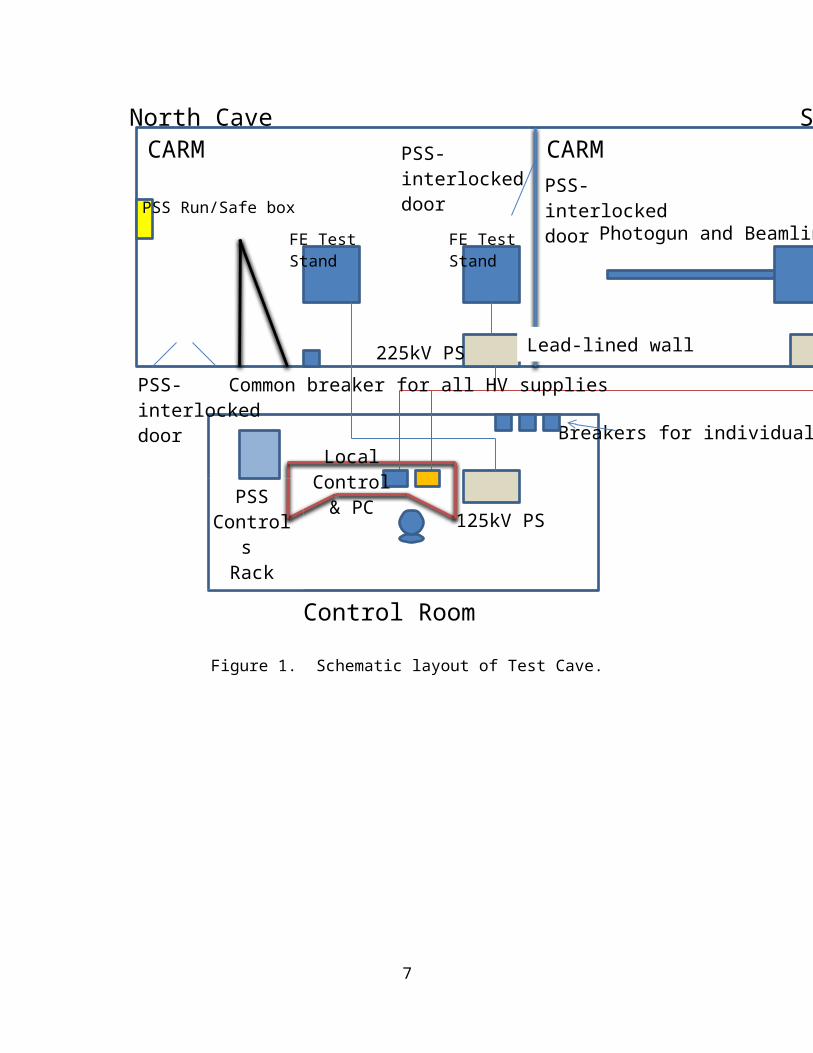
The Injector Test Cave walls and ceiling are constructed of thick concrete block. The Test Cave consists of two workspaces separated by a lead-lined wall and door (see
3
Figure1 below). The North Cave contains field emission test stands (Figures 2 and 3) and the South Cave contains a DC high voltage photogun and beamline (separate SOP, ref A-09-003-SOP). No one can be inside the North Cave when high voltage is applied to the field emission test stands. Similarly, no one can be inside the South Cave when high voltage is applied to the DC high voltage photogun. However, the lead-lined wall and door provides adequate radiation shielding to allow occupancy of the adjacent workspace while high voltage measurements are made in the neighboring workspace (more below).
The system operator of the field emission test stands makes measurements from the Test Cave Control Room adjacent to the Test Cave. The Glassman 125kV power supply is located inside the Control Room, and is operated by adjusting dials on the front panel. The Spellman 225kV power supply is located inside the North Cave, and is operated remotely using a personal computer. Different protocols (described below) are used to guarantee the power supplies are OFF before re-entering the North Cave. Note, there are additional high voltage power supplies inside the Control Room that are used to conduct experiments in the South Cave. These are described in the ITS South Cave Photogun Operations SOP, which can be found in the Control Room.
Power to ALL high voltage power supplies (for North and South Caves) can be removed by setting a single, common knife switch breaker to OFF – this breaker is located on a wall inside the North Cave, as shown in Figure 1. Additional knife switch breakers located inside the Control Room are used to remove AC power from individual high voltage power supplies.
4
100
North Cave South Cave
FE Test Stand
FE Test Stand
Control Room
225kV PS
125kV PS
Photogun and Beamline
Lead-lined wall
CARMCARM
PSS-interlocked door
PSS-interlocked doorPSS Run/Safe box
Common breaker for all HV supplies
Local Control
& PC
PSS-interlocked door
PSS Contro
ls Rack
Breakers for individual HV supplies
225kV PS
Figure 1. Schematic layout of Test Cave.
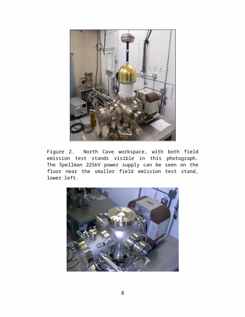
Figure 2. North Cave workspace, with both field emission test stands visible in this photograph. The Spellman 225kV power supply can be seen on the floor near the smaller field emission test stand, lower left.
5
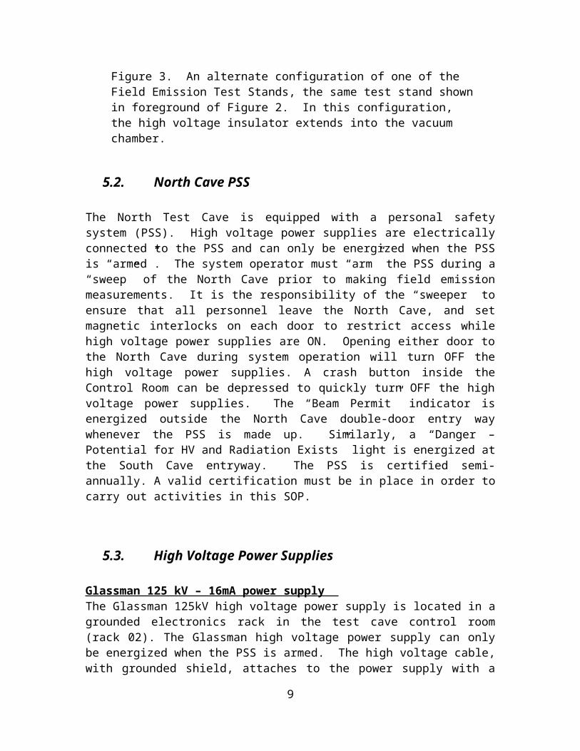
Figure 3. An alternate configuration of one of the Field Emission Test Stands, the same test stand shown in foreground of Figure 2. In this configuration, the high voltage insulator extends into the vacuum chamber.
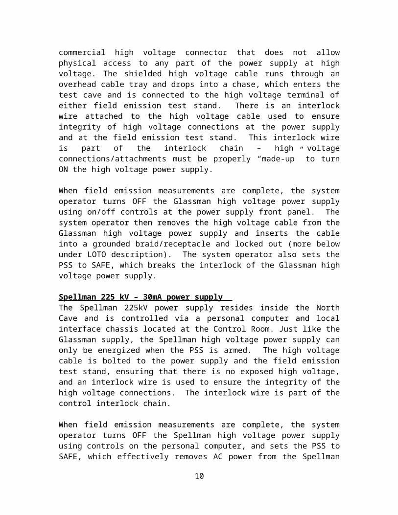
5.2. North Cave PSS
The North Test Cave is equipped with a personal safety system (PSS). High voltage power supplies are electrically connected to the PSS and can only be energized when the PSS is “armed”. The system operator must “arm” the PSS during a “sweep” of the North Cave prior to making field emission measurements. It is the responsibility of the “sweeper” to ensure that all personnel leave the North Cave, and set magnetic interlocks on each door to restrict access while high voltage power supplies are ON. Opening either door to the North Cave during system operation will turn OFF the high voltage power supplies. A crash button inside the Control Room can be depressed to quickly turn OFF the high voltage power supplies. The “Beam Permit” indicator is energized outside the North Cave double-door entry way whenever the PSS is made up. Similarly, a “Danger – Potential for HV and Radiation Exists” light is energized at the South Cave entryway. The PSS is certified semi-annually. A valid certification must be in place in order to carry out activities in this SOP.
5.3. High Voltage Power Supplies
Glassman 125 kV – 16mA power supply The Glassman 125kV high voltage power supply is located in a grounded electronics rack in the test cave control room (rack 02). The Glassman high voltage power supply can only be energized when the PSS is armed. The high voltage cable, with grounded shield, attaches to the power supply with a commercial high voltage connector that does not allow physical access to any part of the power supply at high voltage. The shielded high voltage cable runs through an overhead cable tray and drops into a chase, which enters the test cave and is connected to the high voltage terminal of either field emission test stand. There is an interlock wire attached to the high voltage cable used to ensure integrity of high voltage connections at the power supply and at the field emission test stand. This interlock wire is part of the interlock chain – high voltage connections/attachments must be properly “made-up” to turn ON the high voltage power supply.
When field emission measurements are complete, the system operator turns OFF the Glassman high voltage power supply using on/off controls at the power supply front panel. The system operator then removes the high voltage cable from the Glassman high voltage power supply and inserts the cable into a grounded braid/receptacle and locked out (more below under LOTO description). The system operator also sets the PSS to SAFE, which breaks the interlock of the Glassman high voltage power supply.
6
Spellman 225 kV – 30mA power supply The Spellman 225kV power supply resides inside the North Cave and is controlled via a personal computer and local interface chassis located at the Control Room. Just like the Glassman supply, the Spellman high voltage power supply can only be energized when the PSS is armed. The high voltage cable is bolted to the power supply and the field emission test stand, ensuring that there is no exposed high voltage, and an interlock wire is used to ensure the integrity of the high voltage connections. The interlock wire is part of the control interlock chain.
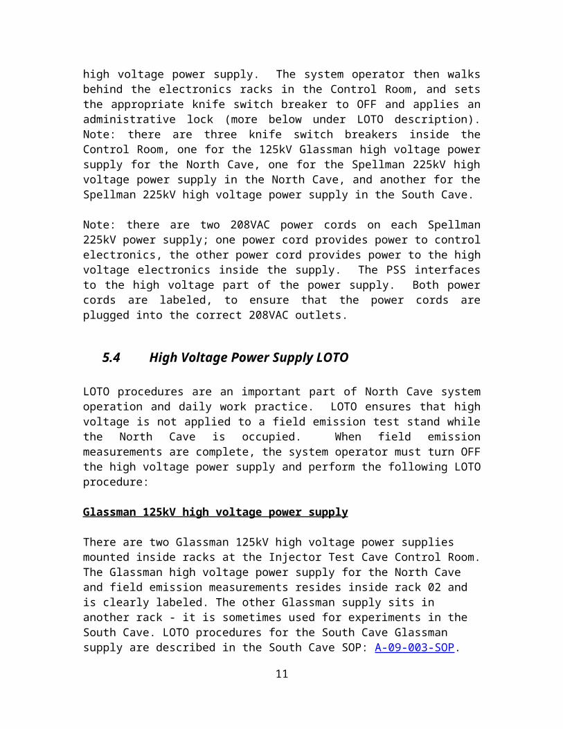
When field emission measurements are complete, the system operator turns OFF the Spellman high voltage power supply using controls on the personal computer, and sets the PSS to SAFE, which effectively removes AC power from the Spellman high voltage power supply. The system operator then walks behind the electronics racks in the Control Room, and sets the appropriate knife switch breaker to OFF and applies an administrative lock (more below under LOTO description). Note: there are three knife switch breakers inside the Control Room, one for the 125kV Glassman high voltage power supply for the North Cave, one for the Spellman 225kV high voltage power supply in the North Cave, and another for the Spellman 225kV high voltage power supply in the South Cave.
Note: there are two 208VAC power cords on each Spellman 225kV power supply; one power cord provides power to control electronics, the other power cord provides power to the high voltage electronics inside the supply. The PSS interfaces to the high voltage part of the power supply. Both power cords are labeled, to ensure that the power cords are plugged into the correct 208VAC outlets.
5.4 High Voltage Power Supply LOTO
LOTO procedures are an important part of North Cave system operation and daily work practice. LOTO ensures that high voltage is not applied to a field emission test stand while the North Cave is occupied. When field emission measurements are complete, the system operator must turn OFF the high voltage power supply and perform the following LOTO procedure:
Glassman 125kV high voltage power supply
There are two Glassman 125kV high voltage power supplies mounted inside racks at the Injector Test Cave Control Room. The Glassman high voltage power supply for the North Cave and field emission measurements resides inside rack 02 and is clearly labeled. The other Glassman supply sits in another rack - it is sometimes used for experiments in the South Cave. LOTO procedures for the South Cave Glassman supply are described in the South Cave SOP: A-09-003-SOP.
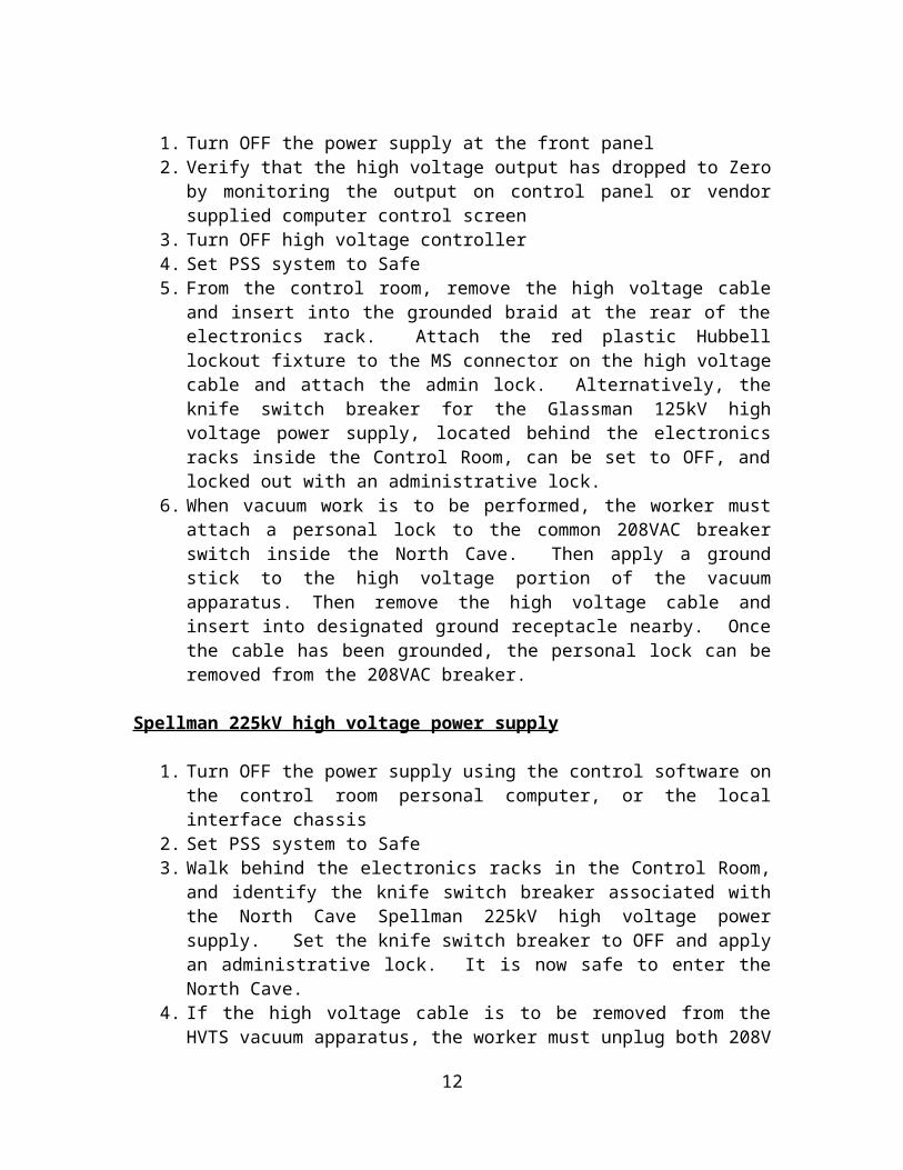
1. Turn OFF the power supply at the front panel
7
2. Verify that the high voltage output has dropped to Zero by monitoring the output on control panel or vendor supplied computer control screen
3. Turn OFF high voltage controller4. Set PSS system to Safe5. From the control room, remove the high voltage cable and insert into the
grounded braid at the rear of the electronics rack. Attach the red plastic Hubbell lockout fixture to the MS connector on the high voltage cable and attach the admin lock. Alternatively, the knife switch breaker for the Glassman 125kV high voltage power supply, located behind the electronics racks inside the Control Room, can be set to OFF, and locked out with an administrative lock.
6. When vacuum work is to be performed, the worker must attach a personal lock to the common 208VAC breaker switch inside the North Cave. Then apply a ground stick to the high voltage portion of the vacuum apparatus. Then remove the high voltage cable and insert into designated ground receptacle nearby. Once the cable has been grounded, the personal lock can be removed from the 208VAC breaker.
Spellman 225kV high voltage power supply
1. Turn OFF the power supply using the control software on the control room personal computer, or the local interface chassis
2. Set PSS system to Safe3. Walk behind the electronics racks in the Control Room, and identify the knife
switch breaker associated with the North Cave Spellman 225kV high voltage power supply. Set the knife switch breaker to OFF and apply an administrative lock. It is now safe to enter the North Cave.
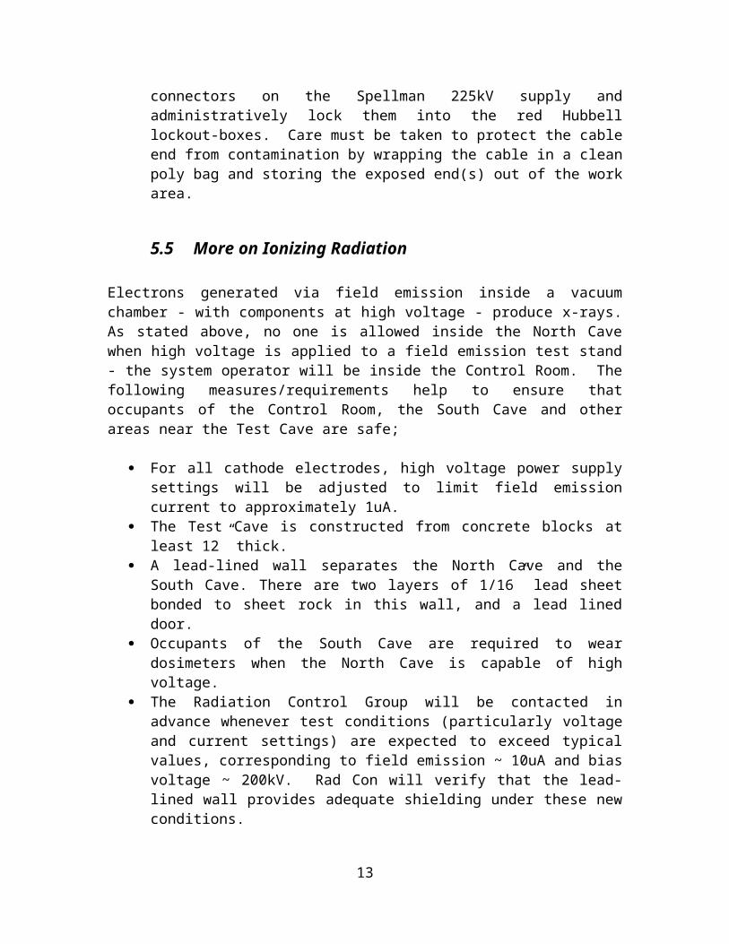
4. If the high voltage cable is to be removed from the HVTS vacuum apparatus, the worker must unplug both 208V connectors on the Spellman 225kV supply and administratively lock them into the red Hubbell lockout-boxes. Care must be taken to protect the cable end from contamination by wrapping the cable in a clean poly bag and storing the exposed end(s) out of the work area.
5.5 More on Ionizing Radiation
Electrons generated via field emission inside a vacuum chamber - with components at high voltage - produce x-rays. As stated above, no one is allowed inside the North Cave when high voltage is applied to a field emission test stand - the system operator will be inside the Control Room. The following measures/requirements help to ensure that occupants of the Control Room, the South Cave and other areas near the Test Cave are safe;
For all cathode electrodes, high voltage power supply settings will be adjusted to limit field emission current to approximately 1uA.
The Test Cave is constructed from concrete blocks at least 12” thick. A lead-lined wall separates the North Cave and the South Cave. There are two
layers of 1/16” lead sheet bonded to sheet rock in this wall, and a lead lined door.
8
Occupants of the South Cave are required to wear dosimeters when the North Cave is capable of high voltage.
The Radiation Control Group will be contacted in advance whenever test conditions (particularly voltage and current settings) are expected to exceed typical values, corresponding to field emission ~ 10uA and bias voltage ~ 200kV. Rad Con will verify that the lead-lined wall provides adequate shielding under these new conditions.
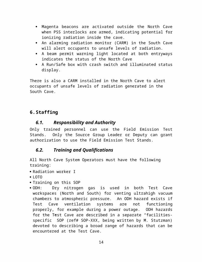
Magenta beacons are activated outside the North Cave when PSS interlocks are armed, indicating potential for ionizing radiation inside the cave.
An alarming radiation monitor (CARM) in the South Cave will alert occupants to unsafe levels of radiation.
A beam permit warning light located at both entryways indicates the status of the North Cave
A Run/Safe box with crash switch and illuminated status display.
There is also a CARM installed in the North Cave to alert occupants of unsafe levels of radiation generated in the South Cave.
6. Staffing
6.1. Responsibility and AuthorityOnly trained personnel can use the Field Emission Test Stands. Only the Source Group Leader or Deputy can grant authorization to use the Field Emission Test Stands.
6.2. Training and Qualifications
All North Cave System Operators must have the following training: Radiation worker I LOTO Training on this SOP ODH: Dry nitrogen gas is used in both Test Cave workspaces (North and South) for
venting ultrahigh vacuum chambers to atmospheric pressure. An ODH hazard exists if Test Cave ventilation systems are not functioning properly, for example during a power outage. ODH hazards for the Test Cave are described in a separate “facilities-specific” SOP (ref# SOP-XXX, being written by M. Stutzman) devoted to describing a broad range of hazards that can be encountered at the Test Cave.
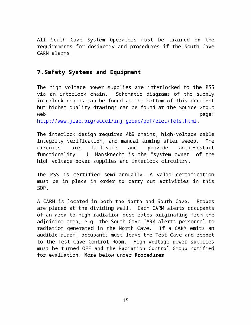
All South Cave System Operators must be trained on the requirements for dosimetry and procedures if the South Cave CARM alarms.
7. Safety Systems and Equipment
9
The high voltage power supplies are interlocked to the PSS via an interlock chain. Schematic diagrams of the supply interlock chains can be found at the bottom of this document but higher quality drawings can be found at the Source Group web page: http://www.jlab.org/accel/inj_group/pdf/elec/fets.html.
The interlock design requires A&B chains, high-voltage cable integrity verification, and manual arming after sweep. The circuits are fail-safe and provide anti-restart functionality. J. Hansknecht is the “system owner” of the high voltage power supplies and interlock circuitry.
The PSS is certified semi-annually. A valid certification must be in place in order to carry out activities in this SOP.
A CARM is located in both the North and South Cave. Probes are placed at the dividing wall. Each CARM alerts occupants of an area to high radiation dose rates originating from the adjoining area; e.g. the South Cave CARM alerts personnel to radiation generated in the North Cave. If a CARM emits an audible alarm, occupants must leave the Test Cave and report to the Test Cave Control Room. High voltage power supplies must be turned OFF and the Radiation Control Group notified for evaluation. More below under Procedures
8. Procedures
8.1. Operating Procedures
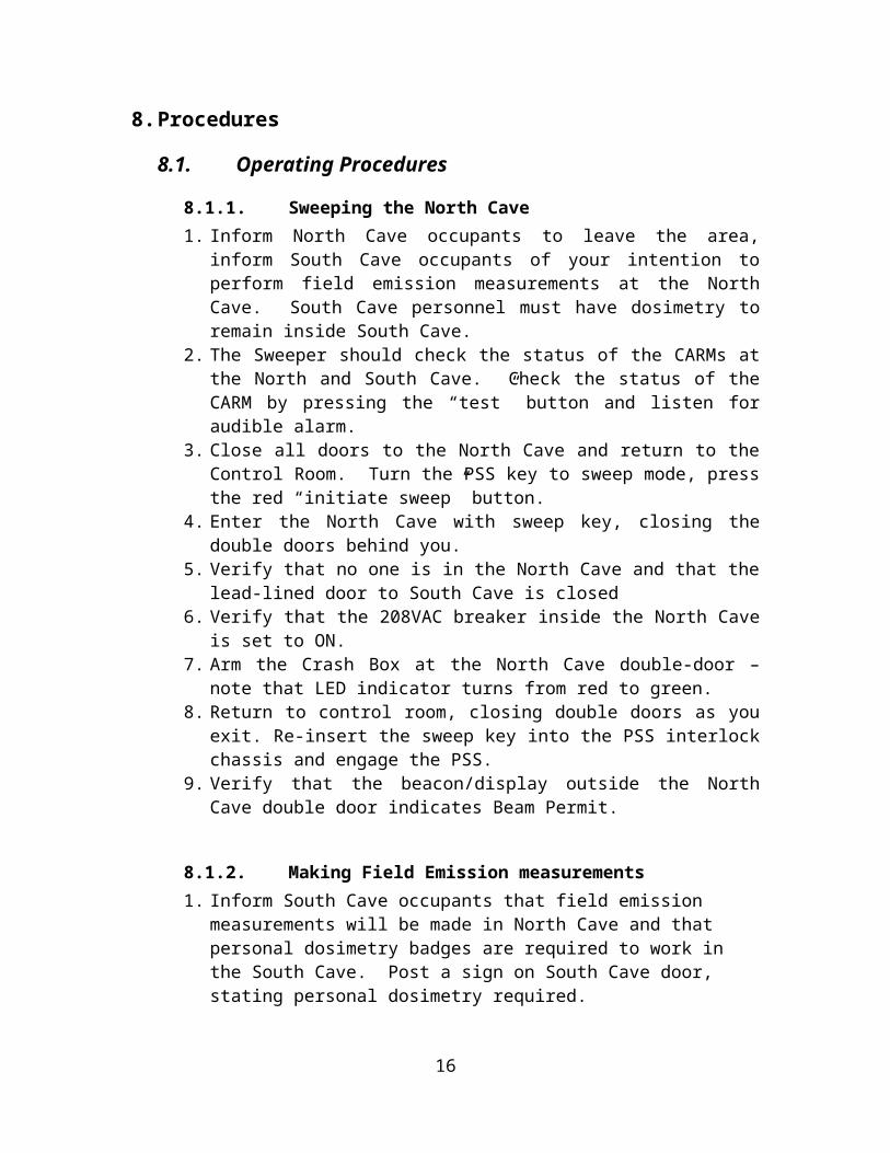
8.1.1. Sweeping the North Cave1. Inform North Cave occupants to leave the area, inform South Cave occupants
of your intention to perform field emission measurements at the North Cave. South Cave personnel must have dosimetry to remain inside South Cave.
2. The Sweeper should check the status of the CARMs at the North and South Cave. Check the status of the CARM by pressing the “test” button and listen for audible alarm.
3. Close all doors to the North Cave and return to the Control Room. Turn the PSS key to sweep mode, press the red “initiate sweep” button.
4. Enter the North Cave with sweep key, closing the double doors behind you.5. Verify that no one is in the North Cave and that the lead-lined door to South
Cave is closed6. Verify that the 208VAC breaker inside the North Cave is set to ON. 7. Arm the Crash Box at the North Cave double-door – note that LED indicator
turns from red to green. 8. Return to control room, closing double doors as you exit. Re-insert the sweep
key into the PSS interlock chassis and engage the PSS. 9. Verify that the beacon/display outside the North Cave double door indicates
Beam Permit.
10
8.1.2. Making Field Emission measurements1. Inform South Cave occupants that field emission measurements will be made
in North Cave and that personal dosimetry badges are required to work in the South Cave. Post a sign on South Cave door, stating personal dosimetry required.
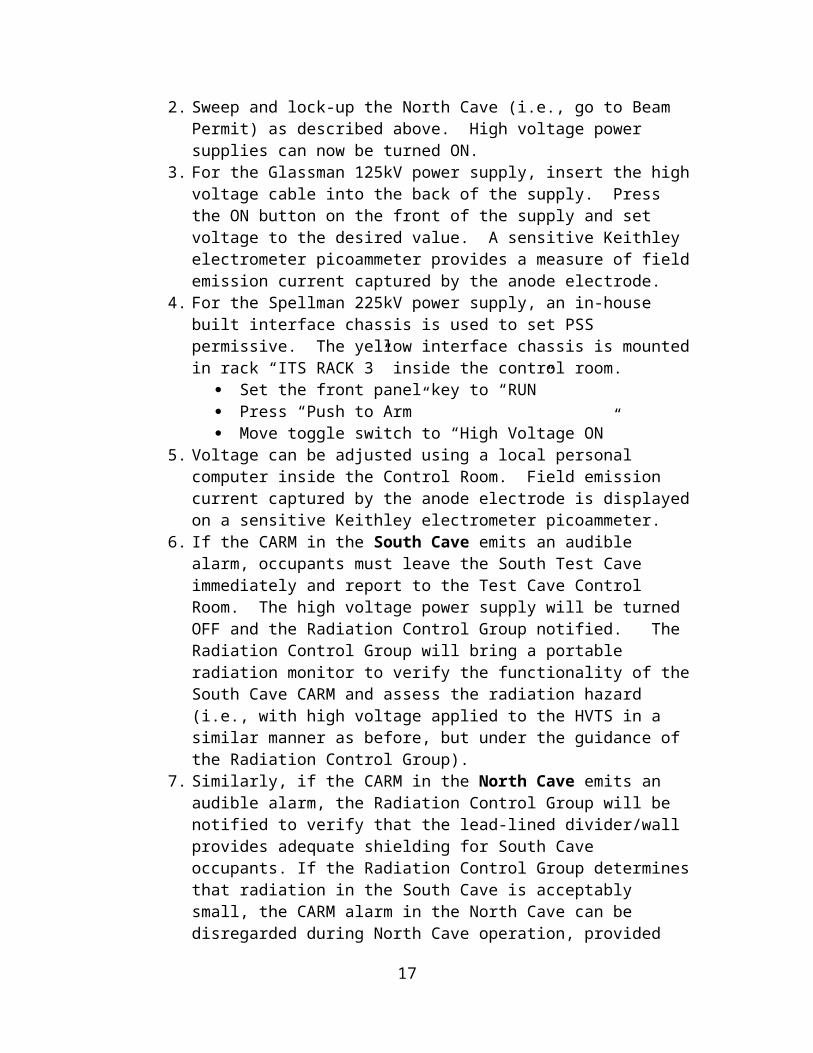
2. Sweep and lock-up the North Cave (i.e., go to Beam Permit) as described above. High voltage power supplies can now be turned ON.
3. For the Glassman 125kV power supply, insert the high voltage cable into the back of the supply. Press the ON button on the front of the supply and set voltage to the desired value. A sensitive Keithley electrometer picoammeter provides a measure of field emission current captured by the anode electrode.
4. For the Spellman 225kV power supply, an in-house built interface chassis is used to set PSS permissive. The yellow interface chassis is mounted in rack “ITS RACK 3” inside the control room.
Set the front panel key to “RUN” Press “Push to Arm” Move toggle switch to “High Voltage ON”
5. Voltage can be adjusted using a local personal computer inside the Control Room. Field emission current captured by the anode electrode is displayed on a sensitive Keithley electrometer picoammeter.
6. If the CARM in the South Cave emits an audible alarm, occupants must leave the South Test Cave immediately and report to the Test Cave Control Room. The high voltage power supply will be turned OFF and the Radiation Control Group notified. The Radiation Control Group will bring a portable radiation monitor to verify the functionality of the South Cave CARM and assess the radiation hazard (i.e., with high voltage applied to the HVTS in a similar manner as before, but under the guidance of the Radiation Control Group).
7. Similarly, if the CARM in the North Cave emits an audible alarm, the Radiation Control Group will be notified to verify that the lead-lined divider/wall provides adequate shielding for South Cave occupants. If the Radiation Control Group determines that radiation in the South Cave is acceptably small, the CARM alarm in the North Cave can be disregarded during North Cave operation, provided voltage applied to the North Cave field emission test stand is not increased.
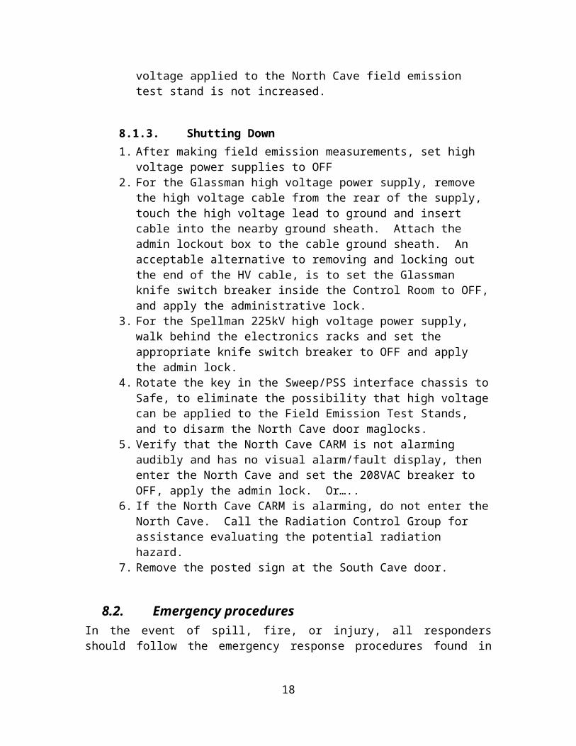
8.1.3. Shutting Down1. After making field emission measurements, set high voltage power supplies to
OFF2. For the Glassman high voltage power supply, remove the high voltage cable
from the rear of the supply, touch the high voltage lead to ground and insert cable into the nearby ground sheath. Attach the admin lockout box to the cable ground sheath. An acceptable alternative to removing and locking out the end of the HV cable, is to set the Glassman knife switch breaker inside the Control Room to OFF, and apply the administrative lock.
11
3. For the Spellman 225kV high voltage power supply, walk behind the electronics racks and set the appropriate knife switch breaker to OFF and apply the admin lock.
4. Rotate the key in the Sweep/PSS interface chassis to Safe, to eliminate the possibility that high voltage can be applied to the Field Emission Test Stands, and to disarm the North Cave door maglocks.
5. Verify that the North Cave CARM is not alarming audibly and has no visual alarm/fault display, then enter the North Cave and set the 208VAC breaker to OFF, apply the admin lock. Or…..
6. If the North Cave CARM is alarming, do not enter the North Cave. Call the Radiation Control Group for assistance evaluating the potential radiation hazard.
7. Remove the posted sign at the South Cave door.
8.2. Emergency proceduresIn the event of spill, fire, or injury, all responders should follow the emergency response procedures found in EH&S Manual or on the "Yellow Cards" attached to the telephone.
An eye wash is located on the external wall (north side) of the Test Cave Control Room, close to the Control Room exit door. An AED (automated external defibrillator) is located outside the Test Cave Control Room, near the Magnet Test Facility, on the north wall of the Test Lab Building 58, approximately 100 feet away from the Test Cave Control Room.
If the status of the Run/Safe shows red ‘UNSAFE” when the North Cave is open for access, hit the nearest crash button and exit immediately. Contact the Safety Systems Group Leader and RadCon Department Head as soon as possible.
If the North Cave CARM alarms, exit the North Cave immediately. Go to the control room and hit the CRASH switch for the SOUTH test cave. Contact RadCon for further instructions.
If the South Cave CARM alarms, exit the North Cave immediately. Go to the control room and hit the CRASH switch for the NORTH test cave. Contact RadCon for further instructions.
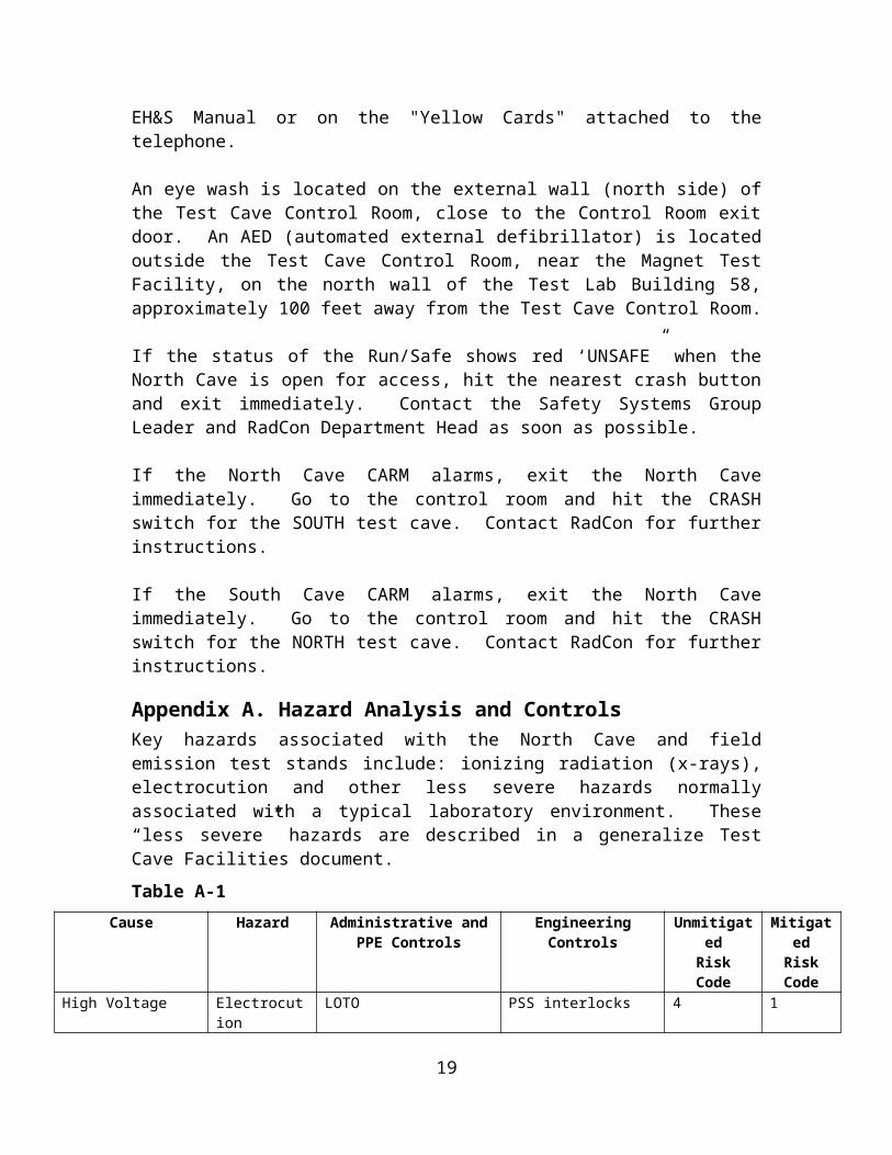
Appendix A. Hazard Analysis and ControlsKey hazards associated with the North Cave and field emission test stands include: ionizing radiation (x-rays), electrocution and other less severe hazards normally associated with a typical laboratory environment. These “less severe” hazards are described in a generalize Test Cave Facilities document.
Table A-1 Cause Hazard Administrative and PPE
ControlsEngineering Controls Unmitigated
RiskMitigated
Risk
12
Code CodeHigh Voltage Electrocution LOTO PSS interlocks 4 1
Table A-2Cause Hazard Administrative and PPE
ControlsEngineering Controls Unmitigated
RiskCode
MitigatedRisk Code
Field Emission x-rays PSS sweep procedure CARM, shielding 4 1
13
All workers participating in field emission measurements shall sign below to indicate that they have read, understand, and agree to perform work according to the SOP.
Acknowledgement of Understanding of SOP
I acknowledge that I have read, understand, and agree to comply with the requirements of the current SOP for field emission measurements at the North Cave, building 58.
NoteYour review and signature will be required again whenever revisions to the document are published. Please fill in the SOP number, and if applicable,
revision level from the cover of the SOP that you have reviewed.
SOP No. and Rev. Printed Name Signature Date
14
Electrical Schematic Diagrams of the North Cave PSS. These diagrams can be viewed with better resolution from http://www.jlab.org/accel/inj_group/pdf/elec/fets.html
15
16
17
18
19