Embed Size (px)
Citation preview
199
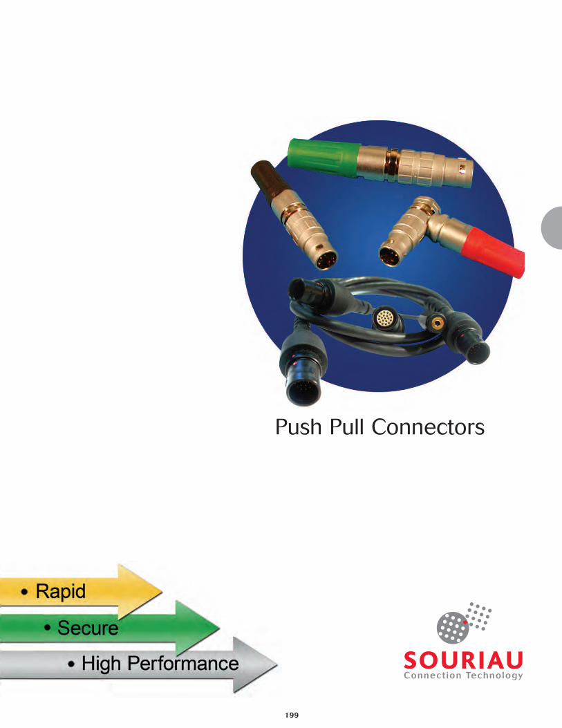
Push Pull Connectors
200
Push-Pull connectors
Introduction
This catalogue presents the push-pull connectors ranges for industrial applica-tions.
These products are particularly suitable for high reliability and high qualityapplications where a simple yet fast method to connect/disconnect isrequired. Also suitable for high endurance and ease of operation in verylimited spaces. The aesthetics of the product allows for perfect integrationon front panel equipments.
SOURIAU offers 3 main series of metallic circular connectors :
• JBX series : basic push-pull series for signal transmission
ContentsWhere and why push-pull ............................................................................................201
Selection guide .............................................................................................................202
Push Pull Connectors
• Main features - Part number system...........................................................................203
• Shell types and dimensions .................................................................................204-206
• Keying..........................................................................................................................207
• Contact layouts ....................................................................................................208-210
• Options ........................................................................................................................211
• Technical characteristics .............................................................................................212
• Wiring and assembly instructions ........................................................................213-217
JBX Series
• Plug Assembly Instructions..................................................................................218-222
• Receptacle Assembly Instructions.......................................................................223-226
Environmentally Sealed Push Pull Connectors
• Main features - Part number system...........................................................................227
• Shell types and dimensions.........................................................................................228
• Keying - contact layouts..............................................................................................229
• Options ........................................................................................................................230
• Technical characteristics .............................................................................................231
• Wiring and assembly instructions ........................................................................232-235
JKX Series
• Plug Assembly Instructions..................................................................................236-241
• Receptacle Assembly Instructions.......................................................................242-245
Push Pull Connectors - Sealed Version Size 2
• Main features - Part number system...........................................................................246
• Shell types and dimensions.........................................................................................247
• Keying - contact layouts..............................................................................................248
• Technical characteristics .............................................................................................249
Sealed Breakaway Connector
• Main features - Part numbering system ......................................................................250
• Shell types and dimensions.........................................................................................251
• Contact layout and Keying ..........................................................................................252
• Technical characteristics......................................................................................253-254
Accessories - Piece parts ....................................................................................255-257
Toolings .................................................................................................................258-259
More about our know-how..........................................................................................260
Requirement form ........................................................................................................261
Conversion table ..........................................................................................................262
All dimensions are in mm

Where and Why push-pull ?
l Extremely fastand easy to use
l A thousand matings/unmatings.
l Enhanced appearance toadd value to equipment
l Space saving
Push-Pull connectors
201
Selection Guide
202
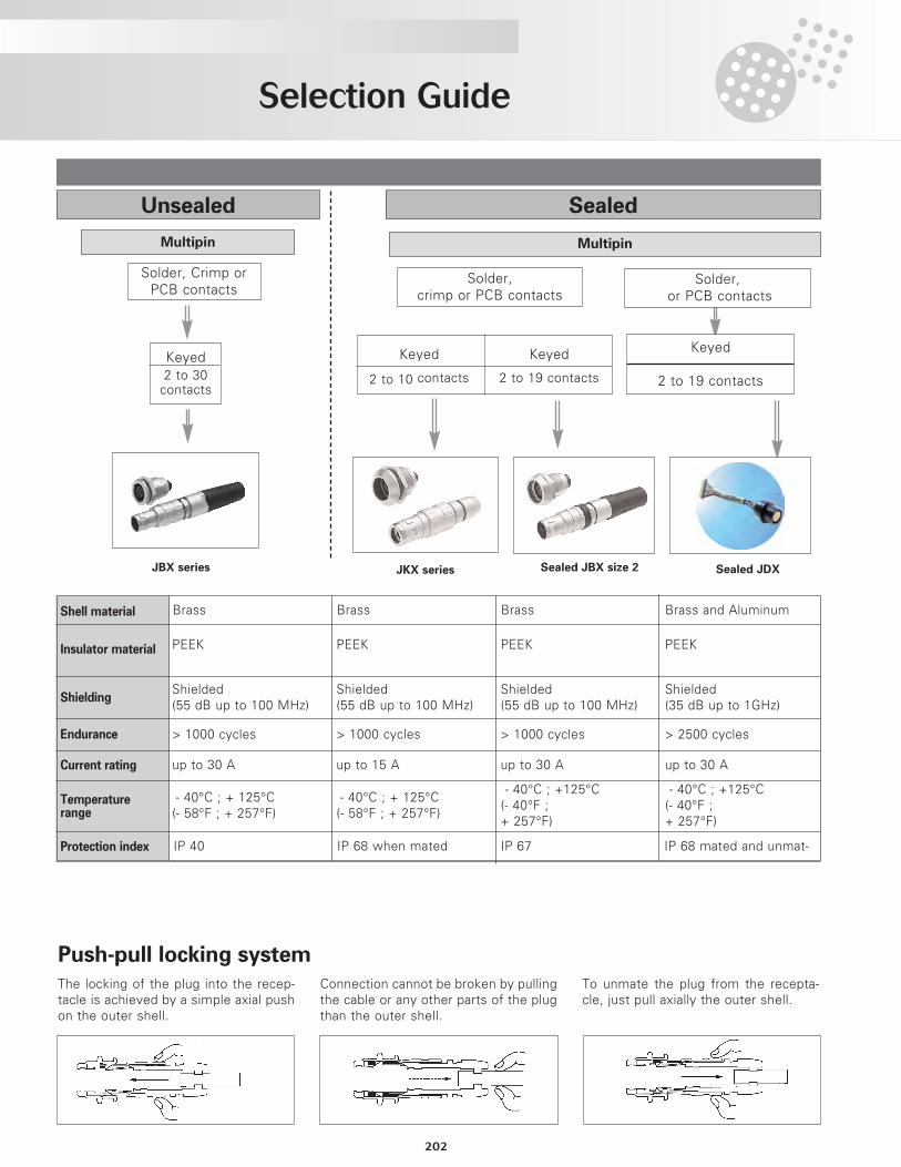
Unsealed Sealed
Multipin Multipin
Keyed
2 to 10 contacts
Keyed
2 to 19 contacts
Keyed2 to 30contacts
The locking of the plug into the recep-tacle is achieved by a simple axial pushon the outer shell.
Connection cannot be broken by pullingthe cable or any other parts of the plugthan the outer shell.
To unmate the plug from the recepta-cle, just pull axially the outer shell.
Push-pull locking system
Brass Brass Brass Brass and Aluminum
PEEK PEEK PEEK PEEK
Shielded(55 dB up to 100 MHz)
Shielded(55 dB up to 100 MHz)
Shielded(55 dB up to 100 MHz)
Shielded(35 dB up to 1GHz)
> 1000 cycles > 1000 cycles > 1000 cycles > 2500 cycles
up to 30 A up to 15 A up to 30 A up to 30 A
- 40°C ; + 125°C(- 58°F ; + 257°F)
- 40°C ; + 125°C(- 58°F ; + 257°F)
- 40°C ; +125°C(- 40°F ; + 257°F)
- 40°C ; +125°C(- 40°F ; + 257°F)
IP 40 IP 68 when mated IP 67 IP 68 mated and unmat-
Shell material
Insulator material
Shielding
Endurance
Current rating
Temperaturerange
Protection index
Solder, Crimp orPCB contacts
Solder,crimp or PCB contacts
JBX series JKX series Sealed JBX size 2
Solder,or PCB contacts
Keyed
2 to 19 contacts
Sealed JDX
Push Pull Connectors
203
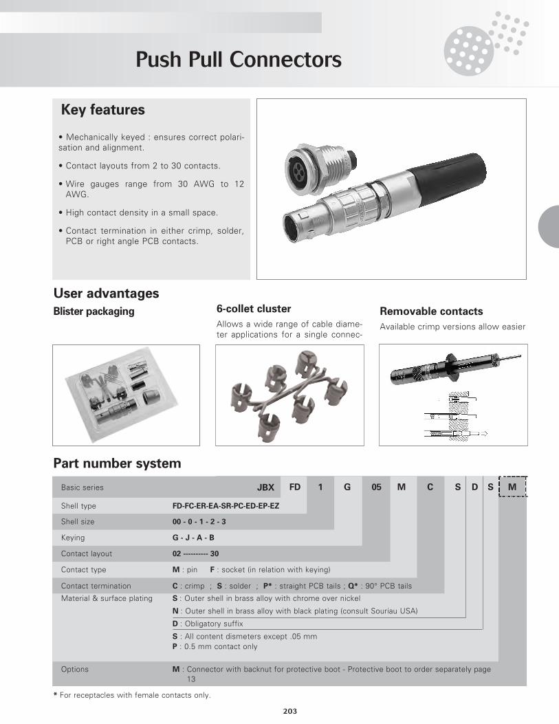
S D SCM05G1FDJBX MBasic series
Shell type FD-FC-ER-EA-SR-PC-ED-EP-EZ
Shell size 00 - 0 - 1 - 2 - 3
Keying G - J - A - B
Contact layout 02 ---------- 30
Contact type M : pin F : socket (in relation with keying)
Contact termination C : crimp ; S : solder ; P* : straight PCB tails ; Q* : 90° PCB tails
Material & surface plating S : Outer shell in brass alloy with chrome over nickel
N : Outer shell in brass alloy with black plating (consult Souriau USA)
D : Obligatory suffix
S : All content dismeters except .05 mmP : 0.5 mm contact only
Options M : Connector with backnut for protective boot - Protective boot to order separately page13
* For receptacles with female contacts only.
• Mechanically keyed : ensures correct polari-sation and alignment.
• Contact layouts from 2 to 30 contacts.
• Wire gauges range from 30 AWG to 12AWG.
• High contact density in a small space.
• Contact termination in either crimp, solder,PCB or right angle PCB contacts.
Key features
Part number system
User advantagesBlister packaging 6-collet cluster
Allows a wide range of cable diame-ter applications for a single connec-
Removable contacts
Available crimp versions allow easier
Push Pull Connectors
204
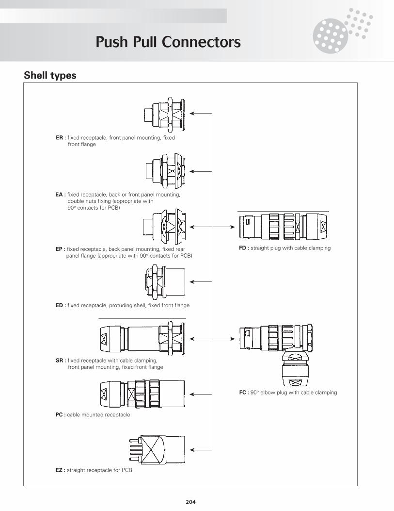
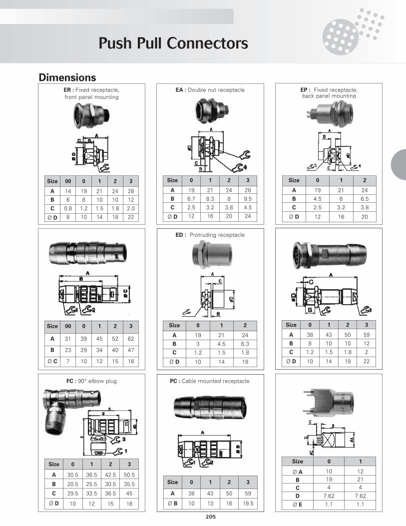
EP : fixed receptacle, back panel mounting, fixed rear panel flange (appropriate with 90° contacts for PCB)
ED : fixed receptacle, protuding shell, fixed front flange
ER : fixed receptacle, front panel mounting, fixed front flange
EA : fixed receptacle, back or front panel mounting, double nuts fixing (appropriate with 90° contacts for PCB)
SR : fixed receptacle with cable clamping, front panel mounting, fixed front flange
PC : cable mounted receptacle
EZ : straight receptacle for PCB
FD : straight plug with cable clamping
FC : 90° elbow plug with cable clamping
Shell types
Push Pull Connectors
205
Dimensions
Size
A
B
Ø C
00
31
23
7
0
39
29
10
1
45
34
12
2
52
40
15
3
62
47
18
FC : 90° elbow plug
Size
A
B
C
Ø D
0
30.5
20.5
29.5
10
1
36.5
25.5
33.5
12
2
42.5
30.5
36.5
15
3
50.5
35.5
45
18
ER : Fixed receptacle,front panel mounting
Size
A
B
C
Ø D
00
14
6
0.8
8
0
19
8
1.2
10
1
21
10
1.5
14
2
24
10
1.8
18
3
28
12
2.0
22
EA : Double nut receptacle
Size
A
B
C
Ø D
0
19
6.7
2.5
12
1
21
8.3
3.2
16
2
24
8
3.8
20
3
28
9.5
4.5
24
Size
A
B
C
Ø D
0
38
8
1.2
10
1
43
10
1.5
14
2
50
10
1.8
18
3
59
12
2
22
PC : Cable mounted receptacle
Size
A
Ø B
0
38
10
1
43
13
2
50
16
3
59
19.5
EP : Fixed receptacle,back panel mounting
Size
A
B
C
Ø D
0
19
4.5
2.5
12
1
21
6
3.2
16
2
24
6.5
3.8
20
ED : Protruding receptacle
Size
A
B
C
Ø D
0
19
3
1.2
10
1
21
4.5
1.5
14
2
24
6.3
1.8
18
Size
Ø A
B
C
D
Ø E
0
10194
7.62
1.1
1
12214
7.62
1.1
206
Push Pull Connectors
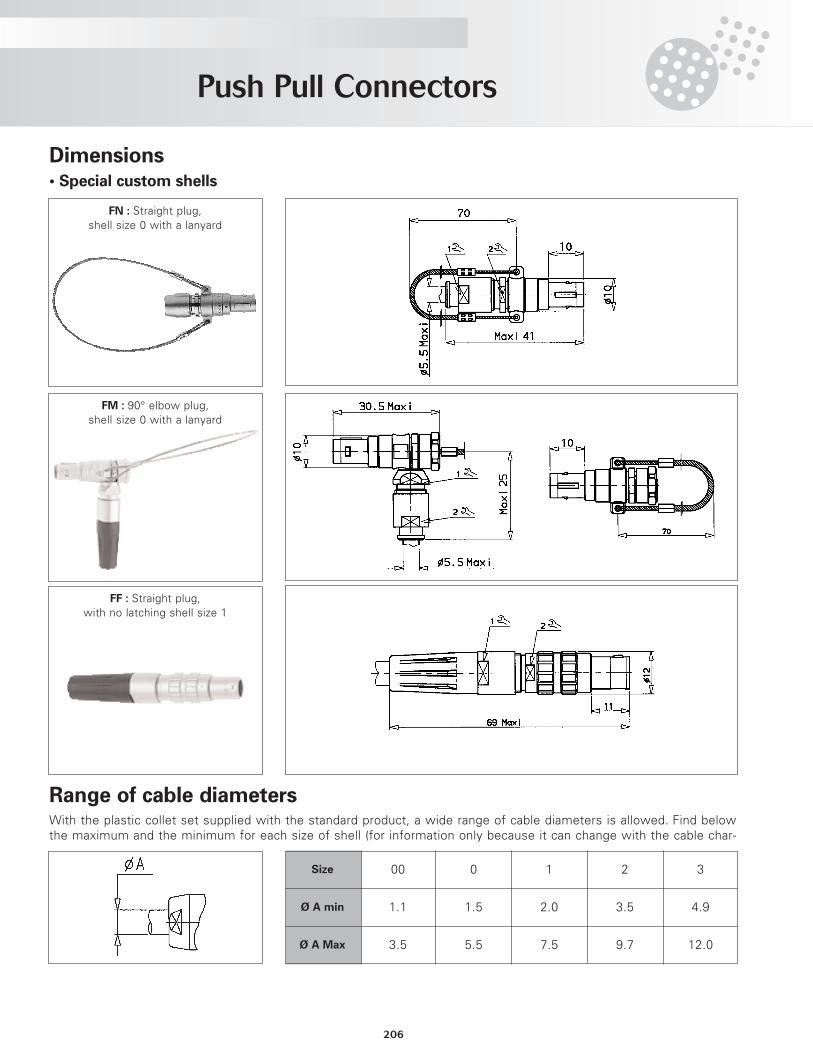
Dimensions
Range of cable diameters
• Special custom shells
FN : Straight plug,shell size 0 with a lanyard
FM : 90° elbow plug,shell size 0 with a lanyard
FF : Straight plug,with no latching shell size 1
With the plastic collet set supplied with the standard product, a wide range of cable diameters is allowed. Find belowthe maximum and the minimum for each size of shell (for information only because it can change with the cable char-
Size 00 0 1 2 3
Ø A min 1.1 1.5 2.0 3.5 4.9
Ø A Max 3.5 5.5 7.5 9.7 12.0
Push Pull Connectors
207
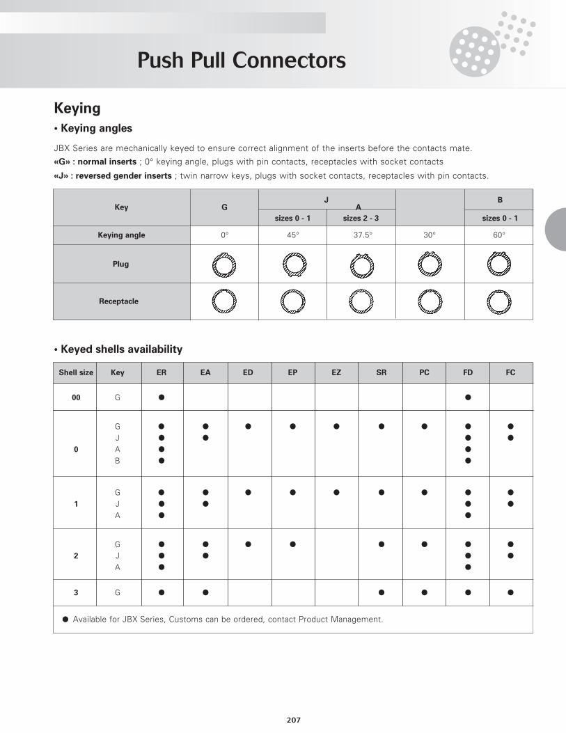
J BKey G A
sizes 0 - 1 sizes 2 - 3 sizes 0 - 1
Keying angle 0° 45° 37.5° 30° 60°
Plug
Receptacle
JBX Series are mechanically keyed to ensure correct alignment of the inserts before the contacts mate.
«G» : normal inserts ; 0° keying angle, plugs with pin contacts, receptacles with socket contacts
«J» : reversed gender inserts ; twin narrow keys, plugs with socket contacts, receptacles with pin contacts.
Keying
• Keying angles
• Keyed shells availability
Shell size Key ER EA ED EP EZ SR PC FD FC
00 G l l
G l l l l l l l l l
J l l l l
0 A l l
B l l
G l l l l l l l l l
1 J l l l l
A l l
G l l l l l l l l
2 J l l l l
A l l
3 G l l l l l l
l Available for JBX Series, Customs can be ordered, contact Product Management.
Push Pull Connectors
208
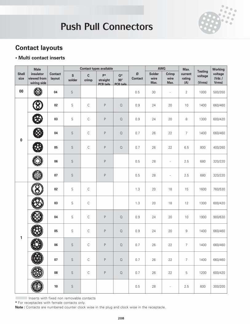
Contact layouts
• Multi contact inserts
Male AWG Max.Testing
Working
Shell insulator Contact S C P* Q* Ø Solder Crimp currentvoltage
voltage
size viewed from layout solder crimp straight 90° Contact wire wire rating (Vdc /
wiring side PCB tails PCB tails Max. Max. (A) (Vrms) Vrms)
04 S 0.5 30 - 2 1000 500/350
02 S C P Q 0.9 24 20 10 1400 660/460
03 S C P Q 0.9 24 20 8 1300 600/420
04 S C P Q 0.7 26 22 7 1400 660/460
05 S C P Q 0.7 26 22 6.5 800 400/260
06 S P 0.5 28 - 2.5 680 320/220
07 S P 0.5 28 - 2.5 680 320/220
02 S C 1.3 20 18 15 1600 760/530
03 S C 1.3 20 18 12 1300 600/420
04 S C P Q 0.9 24 20 10 1900 900/630
05 S C P Q 0.9 24 20 9 1400 660/460
06 S C P Q 0.7 26 22 7 1400 660/460
07 S C P Q 0.7 26 22 7 1400 660/460
08 S C P Q 0.7 26 22 5 1200 600/420
10 S 0.5 28 - 2.5 600 300/200
Inserts with fixed non removable contacts* For receptacles with female contacts only.Note : Contacts are numbered counter clock wise in the plug and clock wise in the receptacle.
Contact types available
00
0
1
Push Pull Connectors
209
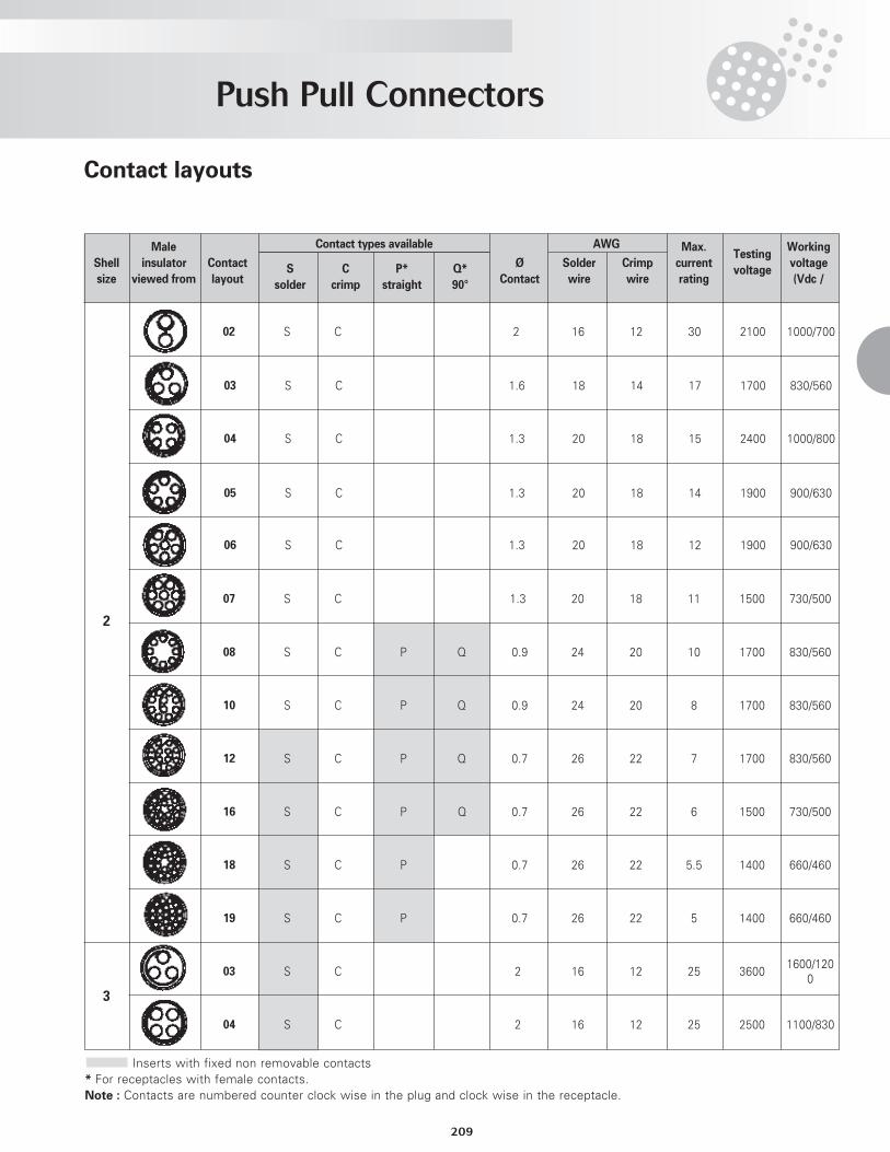
Contact layouts
Male AWG Max.Testing
Working
Shell insulator Contact S C P* Q* Ø Solder Crimp currentvoltage
voltage
size viewed from layout solder crimp straight 90° Contact wire wire rating (Vdc /
02 S C 2 16 12 30 2100 1000/700
03 S C 1.6 18 14 17 1700 830/560
04 S C 1.3 20 18 15 2400 1000/800
05 S C 1.3 20 18 14 1900 900/630
06 S C 1.3 20 18 12 1900 900/630
07 S C 1.3 20 18 11 1500 730/500
08 S C P Q 0.9 24 20 10 1700 830/560
10 S C P Q 0.9 24 20 8 1700 830/560
12 S C P Q 0.7 26 22 7 1700 830/560
16 S C P Q 0.7 26 22 6 1500 730/500
18 S C P 0.7 26 22 5.5 1400 660/460
19 S C P 0.7 26 22 5 1400 660/460
03 S C 2 16 12 25 36001600/120
0
04 S C 2 16 12 25 2500 1100/830
Inserts with fixed non removable contacts* For receptacles with female contacts.Note : Contacts are numbered counter clock wise in the plug and clock wise in the receptacle.
Contact types available
2
3
Push Pull Connectors
210
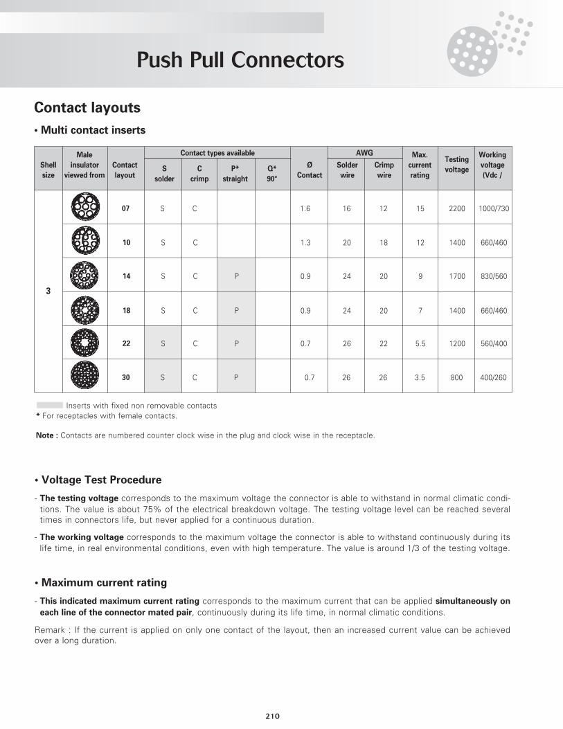
• Voltage Test Procedure
- The testing voltage corresponds to the maximum voltage the connector is able to withstand in normal climatic condi-tions. The value is about 75% of the electrical breakdown voltage. The testing voltage level can be reached severaltimes in connectors life, but never applied for a continuous duration.
- The working voltage corresponds to the maximum voltage the connector is able to withstand continuously during itslife time, in real environmental conditions, even with high temperature. The value is around 1/3 of the testing voltage.
• Maximum current rating
- This indicated maximum current rating corresponds to the maximum current that can be applied simultaneously on
each line of the connector mated pair, continuously during its life time, in normal climatic conditions.
Remark : If the current is applied on only one contact of the layout, then an increased current value can be achievedover a long duration.
Inserts with fixed non removable contacts* For receptacles with female contacts.
Note : Contacts are numbered counter clock wise in the plug and clock wise in the receptacle.
Contact layouts
• Multi contact inserts
Male AWG Max.Testing
Working
Shell insulator Contact S C P* Q* Ø Solder Crimp currentvoltage
voltage
size viewed from layout solder crimp straight 90° Contact wire wire rating (Vdc /
07 S C 1.6 16 12 15 2200 1000/730
10 S C 1.3 20 18 12 1400 660/460
14 S C P 0.9 24 20 9 1700 830/560
18 S C P 0.9 24 20 7 1400 660/460
22 S C P 0.7 26 22 5.5 1200 560/400
30 S C P 0.7 26 26 3.5 800 400/260
Contact types available
3
Push Pull Connectors
211
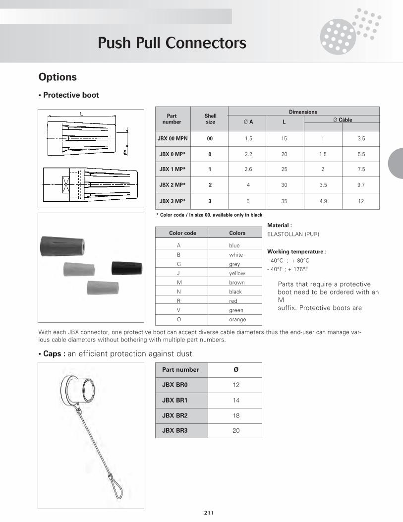
Options
• Protective boot
• Caps : an efficient protection against dust
With each JBX connector, one protective boot can accept diverse cable diameters thus the end-user can manage var-ious cable diameters without bothering with multiple part numbers.
Material :
ELASTOLLAN (PUR)
Working temperature :
- 40°C ; + 80°C
- 40°F ; + 176°F
DimensionsPart Shell
number size Ø A L Ø Câble
JBX 00 MPN 00 1.5 15 1 3.5
JBX 0 MP* 0 2.2 20 1.5 5.5
JBX 1 MP* 1 2.6 25 2 7.5
JBX 2 MP* 2 4 30 3.5 9.7
JBX 3 MP* 3 5 35 4.9 12
Color code Colors
A blue
B white
G grey
J yellow
M brown
N black
R red
V green
O orange
* Color code / In size 00, available only in black
Part number Ø
JBX BR0 12
JBX BR1 14
JBX BR2 18
JBX BR3 20
Parts that require a protectiveboot need to be ordered with anM suffix. Protective boots are
Push Pull Connectors
212
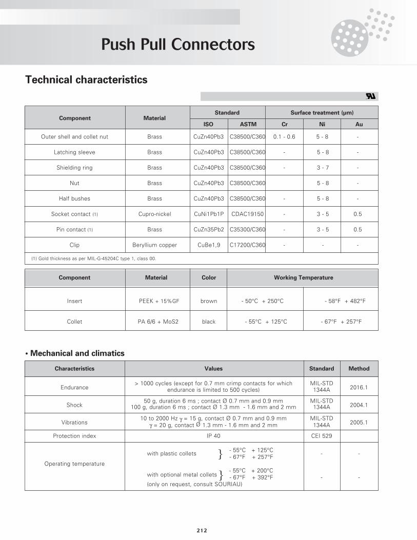
• Mechanical and climatics
Component MaterialStandard Surface treatment (µm)
ISO ASTM Cr Ni Au
Outer shell and collet nut Brass CuZn40Pb3 C38500/C360 0.1 - 0.6 5 - 8 -
Latching sleeve Brass CuZn40Pb3 C38500/C360 - 5 - 8 -
Shielding ring Brass CuZn40Pb3 C38500/C360 - 3 - 7 -
Nut Brass CuZn40Pb3 C38500/C360 5 - 8 -
Half bushes Brass CuZn40Pb3 C38500/C360 - 5 - 8 -
Socket contact (1) Cupro-nickel CuNi1Pb1P CDAC19150 - 3 - 5 0.5
Pin contact (1) Brass CuZn35Pb2 C35300/C360 - 3 - 5 0.5
Clip Beryllium copper CuBe1,9 C17200/C360 - - -
Component Material Color Working Temperature
Insert PEEK + 15%GF brown - 50°C + 250°C - 58°F + 482°F
Collet PA 6/6 + MoS2 black - 55°C + 125°C - 67°F + 257°F
Characteristics Values Standard Method
Endurance> 1000 cycles (except for 0.7 mm crimp contacts for which MIL-STD
2016.1endurance is limited to 500 cycles) 1344A
Shock50 g, duration 6 ms ; contact Ø 0.7 mm and 0.9 mm MIL-STD
2004.1100 g, duration 6 ms ; contact Ø 1.3 mm - 1.6 mm and 2 mm 1344A
Vibrations10 to 2000 Hz γ = 15 g, contact Ø 0.7 mm and 0.9 mm MIL-STD
2005.1γ = 20 g, contact Ø 1.3 mm - 1.6 mm and 2 mm 1344A
Protection index IP 40 CEI 529
- 55°C + 125°Cwith plastic collets
- 67°F + 257°F- -
Operating temperature
with optional metal collets- 55°C + 200°C- 67°F + 392°F - -
(only on request, consult SOURIAU)
(1) Gold thickness as per MIL-G-45204C type 1, class 00.
}
}
Technical characteristics
Push Pull Connectors
213
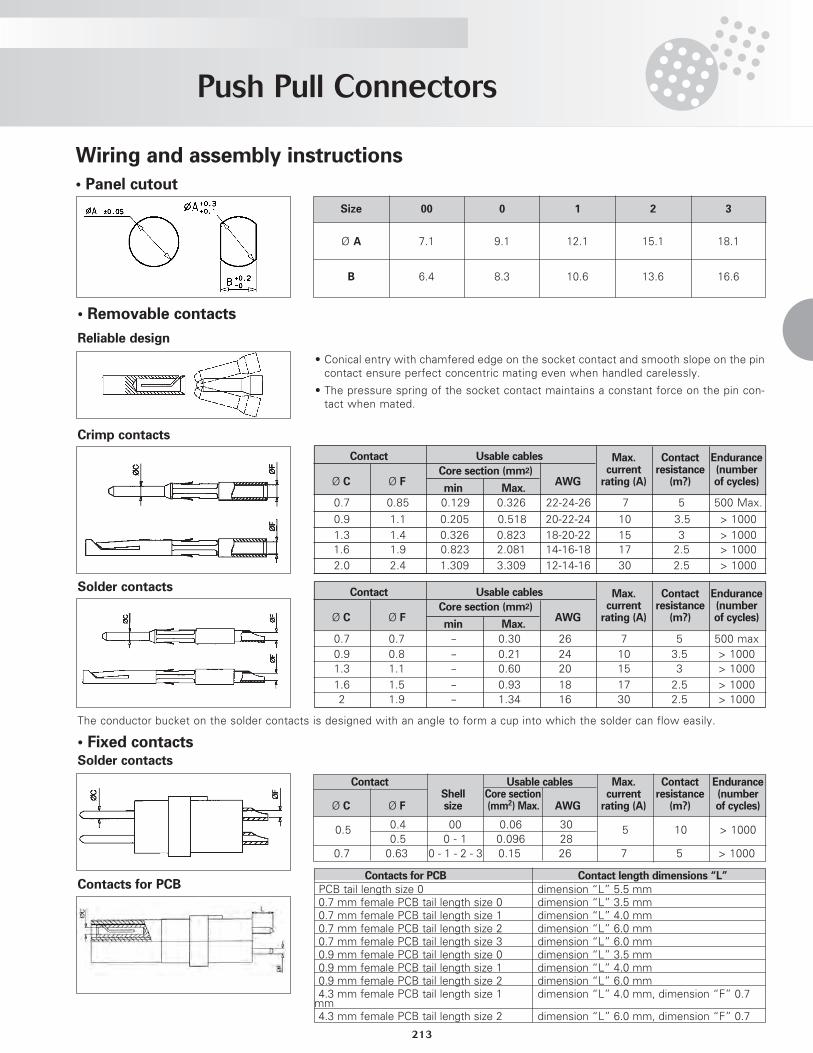
Wiring and assembly instructions
• Panel cutout
Size
Ø A
B
00
7.1
6.4
0
9.1
8.3
1
12.1
10.6
2
15.1
13.6
3
18.1
16.6
• Removable contacts
Reliable design
Crimp contacts
Solder contacts
• Conical entry with chamfered edge on the socket contact and smooth slope on the pincontact ensure perfect concentric mating even when handled carelessly.
• The pressure spring of the socket contact maintains a constant force on the pin con-tact when mated.
Contact Usable cables Max. Contact EnduranceCore section (mm2) current resistance (number
Ø C Ø F AWG rating (A) (m?) of cycles)min Max.
0.7 0.85 0.129 0.326 22-24-26 7 5 500 Max.
0.9 1.1 0.205 0.518 20-22-24 10 3.5 > 10001.3 1.4 0.326 0.823 18-20-22 15 3 > 10001.6 1.9 0.823 2.081 14-16-18 17 2.5 > 10002.0 2.4 1.309 3.309 12-14-16 30 2.5 > 1000
Contact Usable cables Max. Contact EnduranceCore section (mm2) current resistance (number
Ø C Ø F AWG rating (A) (m?) of cycles)min Max.
0.9 0.8 - 0.21 24 10 3.5 > 10000.7 0.7 - 0.30 26 7 5 500 max
1.3 1.1 - 0.60 20 15 3 > 10001.6 1.5 - 0.93 18 17 2.5 > 10002 1.9 - 1.34 16 30 2.5 > 1000
The conductor bucket on the solder contacts is designed with an angle to form a cup into which the solder can flow easily.
• Fixed contactsSolder contacts
Contact Usable cables Max. Contact EnduranceShell Core section current resistance (number
Ø C Ø F size (mm2) Max. AWG rating (A) (m?) of cycles)
0.5 0.4 00 0.06 30 5 10 > 10000.5 0 - 1 0.096 28
0.7 0.63 0 - 1 - 2 - 3 0.15 26 7 5 > 1000
Contacts for PCBContacts for PCB Contact length dimensions “L”
PCB tail length size 0 dimension “L” 5.5 mm0.7 mm female PCB tail length size 0 dimension “L” 3.5 mm0.7 mm female PCB tail length size 1 dimension “L” 4.0 mm0.7 mm female PCB tail length size 2 dimension “L” 6.0 mm0.7 mm female PCB tail length size 3 dimension “L” 6.0 mm0.9 mm female PCB tail length size 0 dimension “L” 3.5 mm0.9 mm female PCB tail length size 1 dimension “L” 4.0 mm0.9 mm female PCB tail length size 2 dimension “L” 6.0 mm4.3 mm female PCB tail length size 1 dimension “L” 4.0 mm, dimension “F” 0.7mm4.3 mm female PCB tail length size 2 dimension “L” 6.0 mm, dimension “F” 0.7
Push Pull Connectors
214
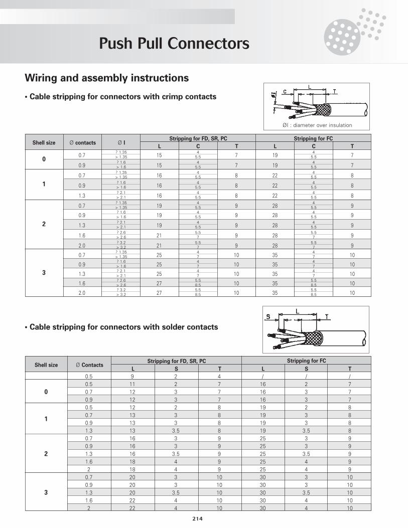
Wiring and assembly instructions
• Cable stripping for connectors with crimp contacts
• Cable stripping for connectors with solder contacts
Stripping for FD, SR, PC Stripping for FC
L C T L C TShell size Ø contacts Ø I
0
1
2
3
Stripping for FD, SR, PC
L S T L S T
0.5 9 2 4 / / /0.5 11 2 7 16 2 70.7 12 3 7 16 3 70.9 12 3 7 16 3 70.5 12 2 8 19 2 80.7 13 3 8 19 3 80.9 13 3 8 19 3 81.3 13 3.5 8 19 3.5 80.7 16 3 9 25 3 90.9 16 3 9 25 3 91.3 16 3.5 9 25 3.5 91.6 18 4 9 25 4 92 18 4 9 25 4 90.7 20 3 10 30 3 100.9 20 3 10 30 3 101.3 20 3.5 10 30 3.5 101.6 22 4 10 30 4 102 22 4 10 30 4 10
Stripping for FC
0
1
2
3
45.5
45.50.7 15 7 19 7
? 1.35> 1.35
45.5
45.50.9 15 7 19 7
? 1.6> 1.6
45.5
45.50.7 16 8 22 8
? 1.35> 1.35
45.5
45.50.9 16 8 22 8
? 1.6> 1.6
45.5
45.51.3 16 8 22 8
? 2.1> 2.1
45.5
45.50.7 19 9 28 9
? 1.35> 1.35
45.5
45.50.9 19 9 28 9
? 1.6> 1.6
45.5
45.51.3 19 9 28 9
? 2.1> 2.1
5.57
5.571.6 21 9 28 9
? 2.6> 2.6
5.57
5.572.0 21 9 28 9
? 3.2> 3.2
47
470.7 25 10 35 10
? 1.35> 1.35
47
470.9 25 10 35 10
? 1.6> 1.6
47
471.3 25 10 35 10
? 2.1> 2.1
5.58.5
5.58.51.6 27 10 35 10
? 2.6> 2.6
5.58.5
5.58.52.0 27 10 35 10
? 3.2> 3.2
ØI : diameter over insulation
Shell size Ø Contacts
Push Pull Connectors
215
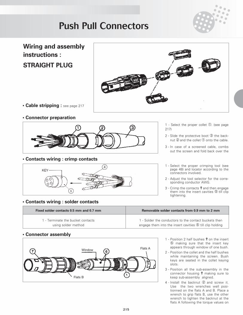
• Cable stripping : see page 217
• Connector preparation
1 - Select the proper collet ¿. (see page217)
2 - Slide the protective boot ¬ the back-nut ¡ and the collet ¿ onto the cable.
3 - In case of a screened cable, combsout the screen and fold back over the
• Contacts wiring : crimp contacts
• Contacts wiring : solder contacts
1 - Select the proper crimping tool (seepage 48) and locator according to theconnectors involved.
2 - Adjust the tool selector for the corre-sponding conductor AWG.
3 - Crimp the contacts ? and then engagethem into the insert cavities ƒ till cliptightening.
• Connector assembly
Fixed solder contacts 0.5 mm and 0.7 mm Removable solder contacts from 0.9 mm to 2 mm
1 - Terminate the bucket contacts 1 - Solder the conductors to the contact buckets thenusing solder method engage them into the insert cavities ƒ till clip holding
Flats B
WindowFlats A
Wiring and assembly
instructions :
STRAIGhT PLUG
1 - Position 2 half bushes ? on the insertƒ making sure that the insert keyappears through window of one bush.
2 - Position the collet and the half busheswhile maintaining the screen. Bushkeys are seated in the collet keyingslots.
3 - Position all the sub-assembly in theconnector housing ? making sure tokeep sub-assembly aligned.
4 - Install the backnut ¡ and screw it.Use the two wrenches well posi-tionned on the flats A and B. Place awrench to grip flats B, use the otherwrench to tighten the backnut at theflats A following the torque values on
Push Pull Connectors
216
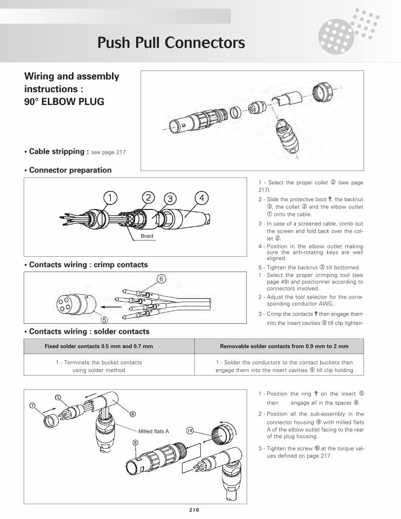
Wiring and assembly
instructions :
90° ELBOW PLUG
• Cable stripping : see page 217
• Connector preparation
1 - Select the proper collet ¡ (see page217).
2 - Slide the protective boot ?, the backnut¬, the collet ¡ and the elbow outlet¿ onto the cable.
3 - In case of a screened cable, comb outthe screen and fold back over the col-let ¡.
4 - Position in the elbow outlet makingsure the anti-rotating keys are wellaligned.
5 - Tighten the backnut ¬ till bottomed.• Contacts wiring : crimp contacts
• Contacts wiring : solder contacts
1 - Select the proper crimping tool (seepage 49) and positionner according toconnectors involved.
2 - Adjust the tool selector for the corre-sponding conductor AWG.
3 - Crimp the contacts ? then engage them
into the insert cavities ƒ till clip tighten-
1 - Position the ring ? on the insert ƒ
then engage all in the spacer «.
2 - Position all the sub-assembly in the
connector housing » with milled flatsA of the elbow outlet facing to the rearof the plug housing.
3 - Tighten the screw … at the torque val-ues defined on page 217.
Fixed solder contacts 0.5 mm and 0.7 mm Removable solder contacts from 0.9 mm to 2 mm
1 - Terminate the bucket contacts 1 - Solder the conductors to the contact buckets thenusing solder method engage them into the insert cavities ƒ till clip holding
Braid
ƒ
Milled flats A
Push Pull Connectors
217
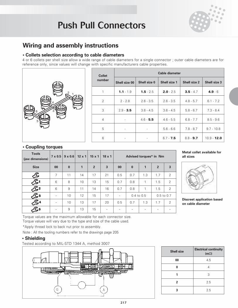
Torque values are the maximum allowable for each connector size.Torque values will vary due to the type and size of the cable used.
*Apply thread lock to back nut prior to assembly.
Note : All the tooling numbers refer to the drawings page 205
• ShieldingTested according to MIL-STD 1344 A, method 3007
Shell sizeElectrical continuity
(mΩ)
00 4.5
0 4
1 3
2 2.5
3 2.5G A
4 or 6 collets per shell size allow a wide range of cable diameters for a single connector ; outer cable diameters are forreference only, since values will change with specific manufacturers cable properties.
Cable diameter
Shell size 0 Shell size 1 Shell size 2 Shell size 3
1 1.1 - 1.9 1.5 - 2.5 2.0 - 2.5 3.5 - 4.7 4.9 - 6
2 2 - 2.8 2.6 - 3.5 2.6 - 3.5 4.8 - 5.7 6.1 - 7.2
3 2.9 - 3.5 3.6 - 4.5 3.6 - 4.5 5.8 - 6.7 7.3 - 8.4
4 - 4.6 - 5.5 4.6 - 5.5 6.8 - 7.7 8.5 - 9.6
5 - - 5.6 - 6.6 7.8 - 8.7 9.7 - 10.8
6 - - 6.7 - 7.5 8.8 - 9.7 10.9 - 12.0
Collet
numberShell size 00
12
3
5
6
4
Wiring and assembly instructions
• Collets selection according to cable diameters
• Coupling torques
Tools7 x 0.5 9 x 0.6 12 x 1 15 x 1 18 x 1 Advised torques* in Nm
(jaw dimensions)
Size 00 0 1 2 3 00 0 1 2 3
7 11 14 17 21 0.5 0.7 1.3 1.7 2
6 8 10 13 15 0.7 0.8 1 1.5 2
6 9 11 14 16 0.7 0.8 1 1.5 2
- 10 12 15 17 - 0.4 to 0.5 0.5 to 0.7
- 10 13 17 20 0.5 0.7 1.3 1.7 2
- 9 13 15 - - - - - -
Metal collet available for
all sizes
Discreet application based
on cable diameter
JBX Plug Assembly Instructions
218
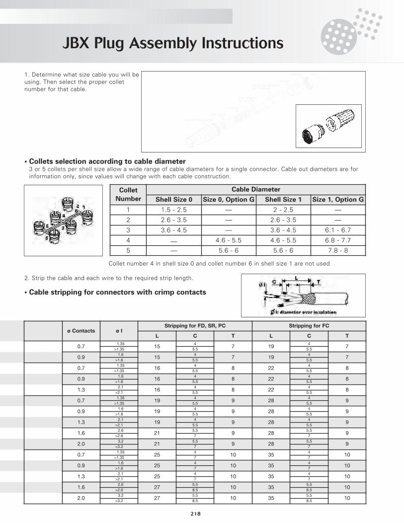
1. Determine what size cable you will beusing. Then select the proper colletnumber for that cable.
• Collets selection according to cable diameter3 or 5 collets per shell size allow a wide range of cable diameters for a single connector. Cable out diameters are forinformation only, since values will change with each cable construction.
Collet number 4 in shell size 0 and collet number 6 in shell size 1 are not used
2. Strip the cable and each wire to the required strip length.
• Cable stripping for connectors with crimp contacts
Collet
Number
Cable Diameter
Shell Size 0 Size 0, Option G Shell Size 1 Size 1, Option G
1 1.5 - 2.5 — 2 - 2.5 —
2 2.6 - 3.5 — 2.6 - 3.5 —
3 3.6 - 4.5 — 3.6 - 4.5 6.1 - 6.7
4 — 4.6 - 5.5 4.6 - 5.5 6.8 - 7.7
5 — 5.6 - 6 5.6 - 6 7.8 - 8
Shell Size ø Contacts ø IStripping for FD, SR, PC Stripping for FC
L C T L C T
00.7
≤1.3515
47 19
47
>1.35 5.5 5.5
0.9≤1.6
154
7 194
7>1.6 5.5 5.5
1
0.7≤1.35
164
8 224
8>1.35 5.5 5.5
0.9≤1.6
164
8 224
8>1.6 5.5 5.5
1.3≤2.1
164
8 224
8>2.1 5.5 5.5
2
0.7≤1.35
194
9 284
9>1.35 5.5 5.5
0.9≤1.6
194
9 284
9>1.6 5.5 5.5
1.3≤2.1
194
9 284
9>2.1 5.5 5.5
1.6≤2.6
215.5
9 285.5
9>2.6 7 7
2.0≤3.2
215.5
9 285.5
9>3.2 7 7
3
0.7≤1.35
254
10 354
10>1.35 7 7
0.9≤1.6
254
10 354
10>1.6 7 7
1.3≤2.1
254
10 354
10>2.1 7 7
1.6≤2.6
275.5
10 355.5
10>2.6 8.5 8.5
2.0≤3.2
275.5
10 355.5
10>3.2 8.5 8.5
JBX Plug Assembly Instructions
219
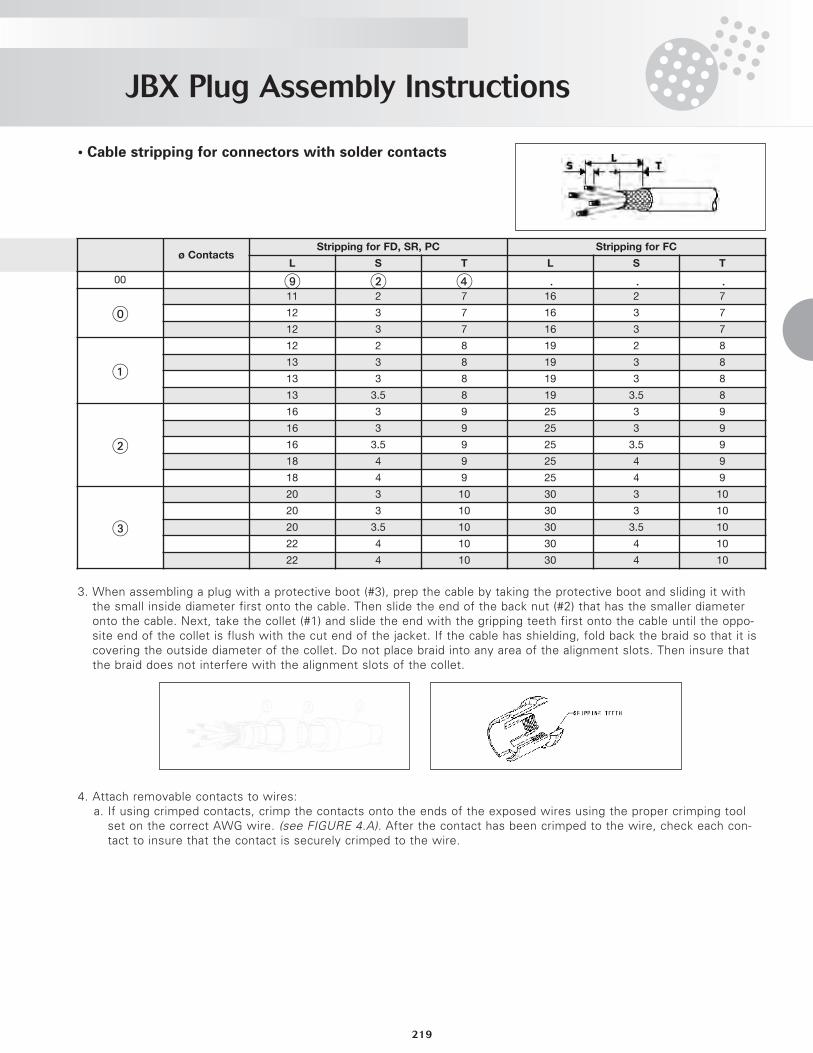
• Cable stripping for connectors with solder contacts
3. When assembling a plug with a protective boot (#3), prep the cable by taking the protective boot and sliding it withthe small inside diameter first onto the cable. Then slide the end of the back nut (#2) that has the smaller diameteronto the cable. Next, take the collet (#1) and slide the end with the gripping teeth first onto the cable until the oppo-site end of the collet is flush with the cut end of the jacket. If the cable has shielding, fold back the braid so that it iscovering the outside diameter of the collet. Do not place braid into any area of the alignment slots. Then insure thatthe braid does not interfere with the alignment slots of the collet.
4. Attach removable contacts to wires:a. If using crimped contacts, crimp the contacts onto the ends of the exposed wires using the proper crimping tool
set on the correct AWG wire. (see FIGURE 4.A). After the contact has been crimped to the wire, check each con-tact to insure that the contact is securely crimped to the wire.
Shell Size ø ContactsStripping for FD, SR, PC Stripping for FC
L S T L S T
00 9 2 4 / / /
011 2 7 16 2 7
12 3 7 16 3 7
12 3 7 16 3 7
1
12 2 8 19 2 8
13 3 8 19 3 8
13 3 8 19 3 8
13 3.5 8 19 3.5 8
2
16 3 9 25 3 9
16 3 9 25 3 9
16 3.5 9 25 3.5 9
18 4 9 25 4 9
18 4 9 25 4 9
3
20 3 10 30 3 10
20 3 10 30 3 10
20 3.5 10 30 3.5 10
22 4 10 30 4 10
22 4 10 30 4 10
JBX Plug Assembly Instructions
220
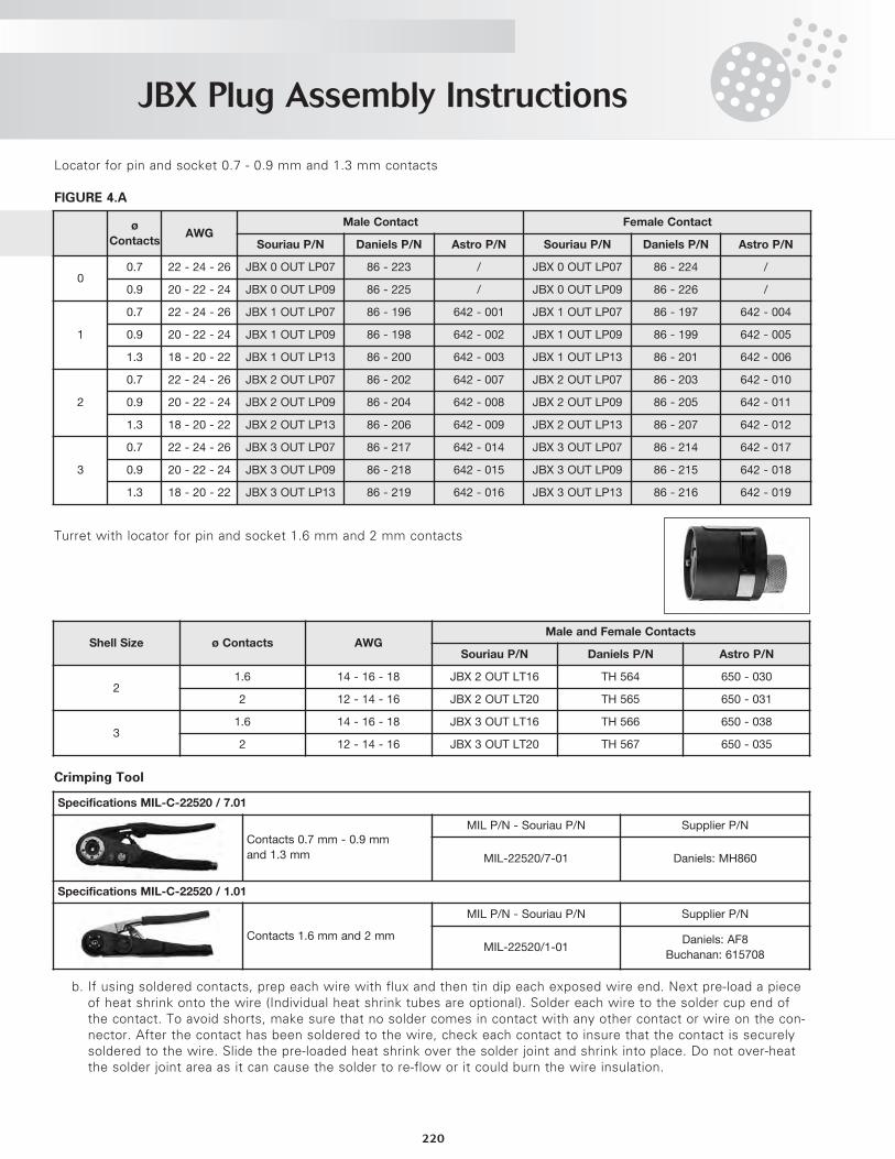
Locator for pin and socket 0.7 - 0.9 mm and 1.3 mm contacts
FIGURE 4.A
Turret with locator for pin and socket 1.6 mm and 2 mm contacts
Crimping Tool
b. If using soldered contacts, prep each wire with flux and then tin dip each exposed wire end. Next pre-load a pieceof heat shrink onto the wire (Individual heat shrink tubes are optional). Solder each wire to the solder cup end ofthe contact. To avoid shorts, make sure that no solder comes in contact with any other contact or wire on the con-nector. After the contact has been soldered to the wire, check each contact to insure that the contact is securelysoldered to the wire. Slide the pre-loaded heat shrink over the solder joint and shrink into place. Do not over-heatthe solder joint area as it can cause the solder to re-flow or it could burn the wire insulation.
Shell
Size
ø
ContactsAWG
Male Contact Female Contact
Souriau P/N Daniels P/N Astro P/N Souriau P/N Daniels P/N Astro P/N
00.7 22 - 24 - 26 JBX 0 OUT LP07 86 - 223 / JBX 0 OUT LP07 86 - 224 /
0.9 20 - 22 - 24 JBX 0 OUT LP09 86 - 225 / JBX 0 OUT LP09 86 - 226 /
1
0.7 22 - 24 - 26 JBX 1 OUT LP07 86 - 196 642 - 001 JBX 1 OUT LP07 86 - 197 642 - 004
0.9 20 - 22 - 24 JBX 1 OUT LP09 86 - 198 642 - 002 JBX 1 OUT LP09 86 - 199 642 - 005
1.3 18 - 20 - 22 JBX 1 OUT LP13 86 - 200 642 - 003 JBX 1 OUT LP13 86 - 201 642 - 006
2
0.7 22 - 24 - 26 JBX 2 OUT LP07 86 - 202 642 - 007 JBX 2 OUT LP07 86 - 203 642 - 010
0.9 20 - 22 - 24 JBX 2 OUT LP09 86 - 204 642 - 008 JBX 2 OUT LP09 86 - 205 642 - 011
1.3 18 - 20 - 22 JBX 2 OUT LP13 86 - 206 642 - 009 JBX 2 OUT LP13 86 - 207 642 - 012
3
0.7 22 - 24 - 26 JBX 3 OUT LP07 86 - 217 642 - 014 JBX 3 OUT LP07 86 - 214 642 - 017
0.9 20 - 22 - 24 JBX 3 OUT LP09 86 - 218 642 - 015 JBX 3 OUT LP09 86 - 215 642 - 018
1.3 18 - 20 - 22 JBX 3 OUT LP13 86 - 219 642 - 016 JBX 3 OUT LP13 86 - 216 642 - 019
Shell Size ø Contacts AWGMale and Female Contacts
Souriau P/N Daniels P/N Astro P/N
21.6 14 - 16 - 18 JBX 2 OUT LT16 TH 564 650 - 030
2 12 - 14 - 16 JBX 2 OUT LT20 TH 565 650 - 031
31.6 14 - 16 - 18 JBX 3 OUT LT16 TH 566 650 - 038
2 12 - 14 - 16 JBX 3 OUT LT20 TH 567 650 - 035
Specifications MIL-C-22520 / 7.01
Contacts 0.7 mm - 0.9 mm
and 1.3 mm
MIL P/N - Souriau P/N Supplier P/N
MIL-22520/7-01 Daniels: MH860
Specifications MIL-C-22520 / 1.01
Contacts 1.6 mm and 2 mm
MIL P/N - Souriau P/N Supplier P/N
MIL-22520/1-01Daniels: AF8
Buchanan: 615708
JBX Plug Assembly Instructions
221
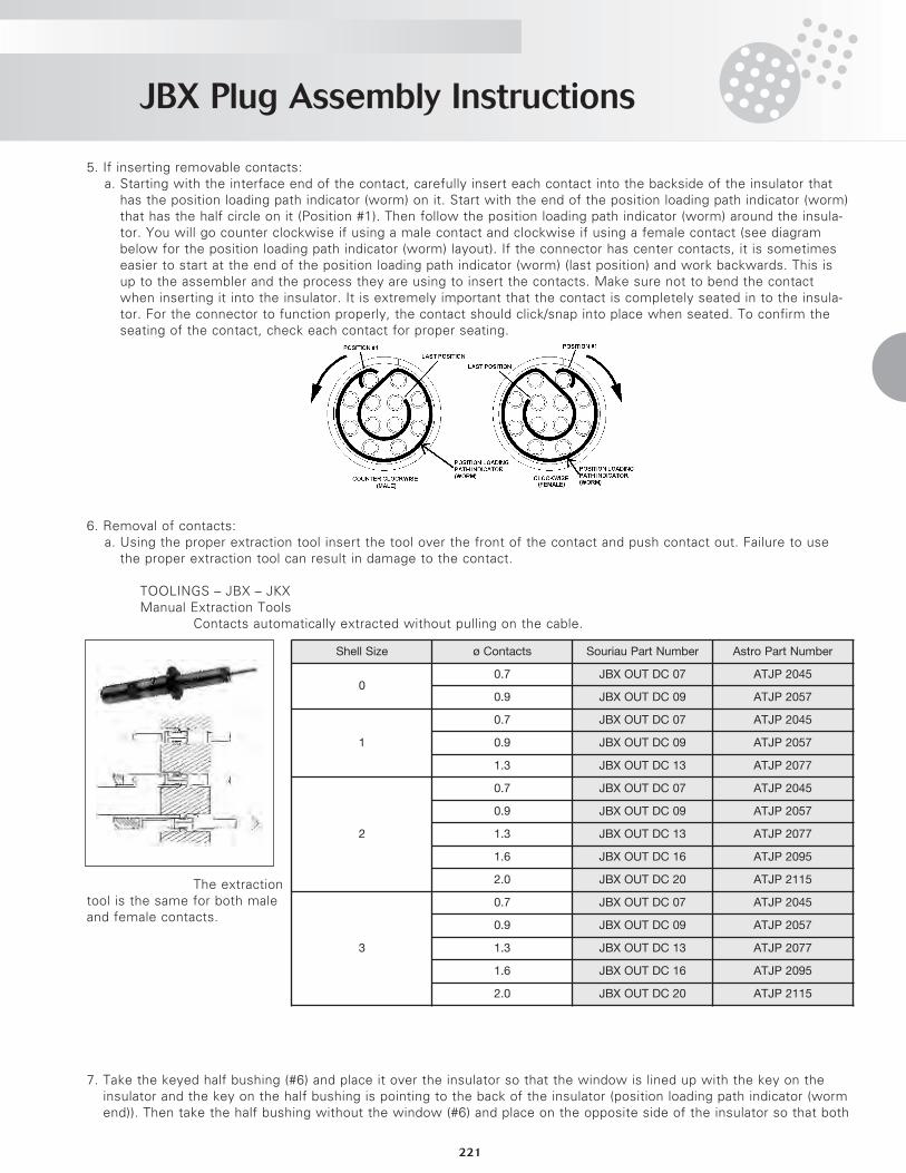
5. If inserting removable contacts:a. Starting with the interface end of the contact, carefully insert each contact into the backside of the insulator that
has the position loading path indicator (worm) on it. Start with the end of the position loading path indicator (worm)that has the half circle on it (Position #1). Then follow the position loading path indicator (worm) around the insula-tor. You will go counter clockwise if using a male contact and clockwise if using a female contact (see diagrambelow for the position loading path indicator (worm) layout). If the connector has center contacts, it is sometimeseasier to start at the end of the position loading path indicator (worm) (last position) and work backwards. This isup to the assembler and the process they are using to insert the contacts. Make sure not to bend the contactwhen inserting it into the insulator. It is extremely important that the contact is completely seated in to the insula-tor. For the connector to function properly, the contact should click/snap into place when seated. To confirm theseating of the contact, check each contact for proper seating.
6. Removal of contacts:a. Using the proper extraction tool insert the tool over the front of the contact and push contact out. Failure to use
the proper extraction tool can result in damage to the contact.
TOOLINGS – JBX – JKXManual Extraction Tools
Contacts automatically extracted without pulling on the cable.
The extractiontool is the same for both maleand female contacts.
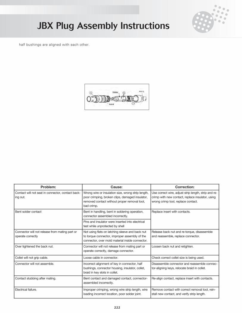
7. Take the keyed half bushing (#6) and place it over the insulator so that the window is lined up with the key on theinsulator and the key on the half bushing is pointing to the back of the insulator (position loading path indicator (wormend)). Then take the half bushing without the window (#6) and place on the opposite side of the insulator so that both
Shell Size ø Contacts Souriau Part Number Astro Part Number
00.7 JBX OUT DC 07 ATJP 2045
0.9 JBX OUT DC 09 ATJP 2057
1
0.7 JBX OUT DC 07 ATJP 2045
0.9 JBX OUT DC 09 ATJP 2057
1.3 JBX OUT DC 13 ATJP 2077
2
0.7 JBX OUT DC 07 ATJP 2045
0.9 JBX OUT DC 09 ATJP 2057
1.3 JBX OUT DC 13 ATJP 2077
1.6 JBX OUT DC 16 ATJP 2095
2.0 JBX OUT DC 20 ATJP 2115
3
0.7 JBX OUT DC 07 ATJP 2045
0.9 JBX OUT DC 09 ATJP 2057
1.3 JBX OUT DC 13 ATJP 2077
1.6 JBX OUT DC 16 ATJP 2095
2.0 JBX OUT DC 20 ATJP 2115
JBX Plug Assembly Instructions
222
half bushings are aligned with each other.
Problem: Cause: Correction:
Contact will not seat in connector, contact back-
ing out.
Wrong wire or insulation size, wrong strip length,
poor crimping, broken clips, damaged insulator,
removed contact without proper removal tool,
bad crimp.
Use correct wire, adjust strip length, strip and re-
crimp with new contact, replace insulator, using
wrong crimp tool, replace contact.
Bent solder contact Bent in handling, bent in soldering operation,
connector assembled incorrectly.
Replace insert with contacts.
Pins and insulator were inserted into electrical
test while unprotected by shell
Connector will not release from mating part or
operate correctly
Not using flats on latching sleeve and back nut
to torque connector, improper assembly of the
connector, over mold material inside connector.
Release back nut and re-torque, disassemble
and reassemble, replace connector.
Over tightened the back nut. Connector will not release from mating part or
operate correctly, damage connector.
Loosen back nut and retighten.
Collet will not grip cable. Loose cable in connector. Check correct collet size is being used.
Connector will not assemble. Incorrect alignment of key in connector, half
bushings, connector housing, insulator, collet,
braid in key slots in collet.
Disassemble connector and reassemble connec-
tor-aligning keys, relocate braid in collet.
Contact stubbing after mating. Bent contact and damaged contact, connector-
assembled incorrectly.
Re-align contact, replace insert with contacts.
Electrical failure. Improper crimping, wrong wire strip length, wire
loading incorrect location, poor solder joint.
Remove contact with correct removal tool, rein-
stall new contact, and verify strip length.
JBX Receptacle Assembly Instructions
223
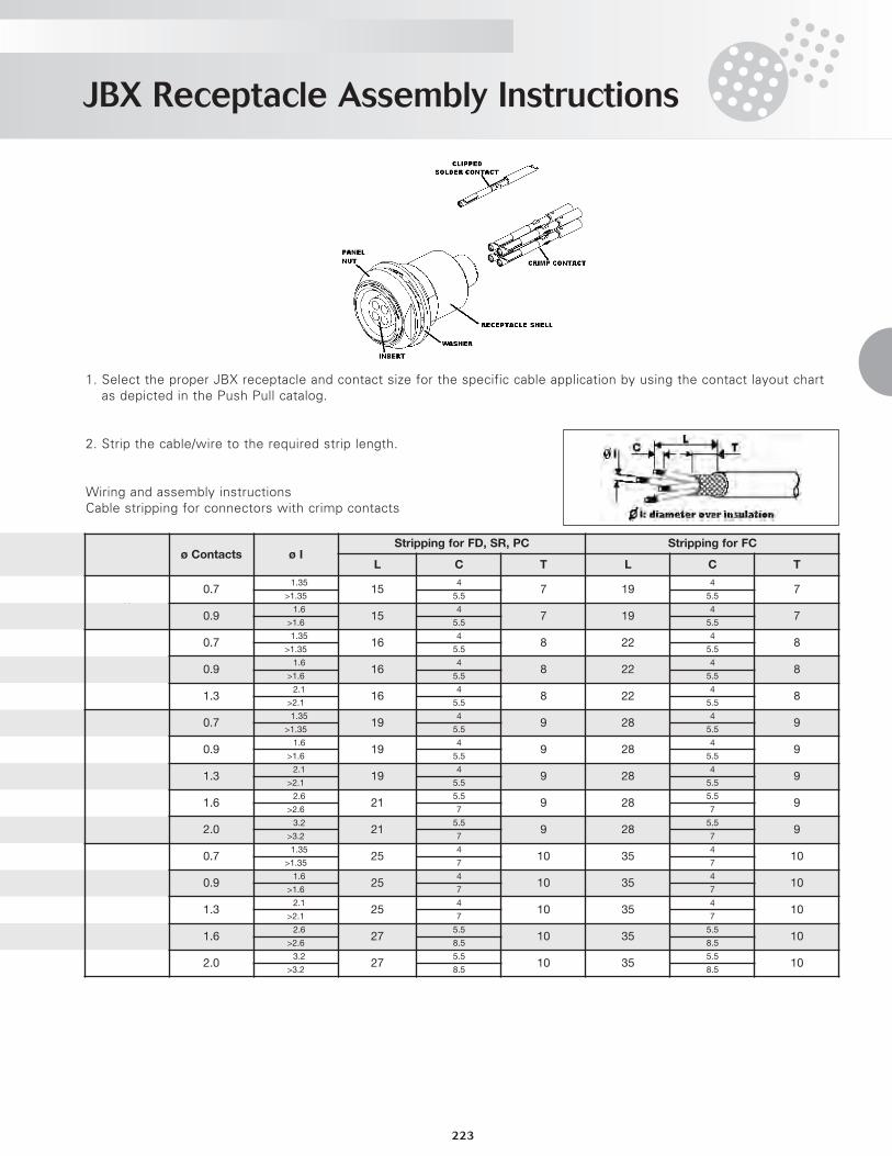
1. Select the proper JBX receptacle and contact size for the specific cable application by using the contact layout chartas depicted in the Push Pull catalog.
2. Strip the cable/wire to the required strip length.
Wiring and assembly instructionsCable stripping for connectors with crimp contacts
Shell Size ø Contacts ø IStripping for FD, SR, PC Stripping for FC
L C T L C T
00.7
≤1.3515
47 19
47
>1.35 5.5 5.5
0.9≤1.6
154
7 194
7>1.6 5.5 5.5
1
0.7≤1.35
164
8 224
8>1.35 5.5 5.5
0.9≤1.6
164
8 224
8>1.6 5.5 5.5
1.3≤2.1
164
8 224
8>2.1 5.5 5.5
2
0.7≤1.35
194
9 284
9>1.35 5.5 5.5
0.9≤1.6
194
9 284
9>1.6 5.5 5.5
1.3≤2.1
194
9 284
9>2.1 5.5 5.5
1.6≤2.6
215.5
9 285.5
9>2.6 7 7
2.0≤3.2
215.5
9 285.5
9>3.2 7 7
3
0.7≤1.35
254
10 354
10>1.35 7 7
0.9≤1.6
254
10 354
10>1.6 7 7
1.3≤2.1
254
10 354
10>2.1 7 7
1.6≤2.6
275.5
10 355.5
10>2.6 8.5 8.5
2.0≤3.2
275.5
10 355.5
10>3.2 8.5 8.5
JBX Receptacle Assembly Instructions
224
Wiring and assembly instructionsCable stripping for connectors with solder contacts
3. Depending on application and shell type, the nut and washer may be removed before attaching the wires to the con-tacts.
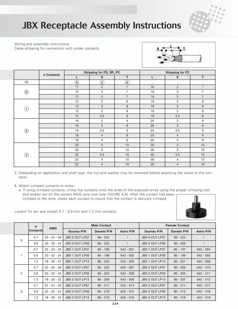
4. Attach crimped contacts to wires:a. If using crimped contacts, crimp the contacts onto the ends of the exposed wires using the proper crimping tool
and locator set on the correct AWG wire size (see FIGURE 4.A). After the contact has beencrimped to the wire, check each contact to insure that the contact is securely crimped.
Locator for pin and socket 0.7 - 0.9 mm and 1.3 mm contacts
Shell Size ø ContactsStripping for FD, SR, PC Stripping for FC
L S T L S T
00 9 2 4 / / /
011 2 7 16 2 7
12 3 7 16 3 7
12 3 7 16 3 7
1
12 2 8 19 2 8
13 3 8 19 3 8
13 3 8 19 3 8
13 3.5 8 19 3.5 8
2
16 3 9 25 3 9
16 3 9 25 3 9
16 3.5 9 25 3.5 9
18 4 9 25 4 9
18 4 9 25 4 9
3
20 3 10 30 3 10
20 3 10 30 3 10
20 3.5 10 30 3.5 10
22 4 10 30 4 10
22 4 10 30 4 10
Shell
Size
ø
ContactsAWG
Male Contact Female Contact
Souriau P/N Daniels P/N Astro P/N Souriau P/N Daniels P/N Astro P/N
00.7 22 - 24 - 26 JBX 0 OUT LP07 86 - 223 / JBX 0 OUT LP07 86 - 224 /
0.9 20 - 22 - 24 JBX 0 OUT LP09 86 - 225 / JBX 0 OUT LP09 86 - 226 /
1
0.7 22 - 24 - 26 JBX 1 OUT LP07 86 - 196 642 - 001 JBX 1 OUT LP07 86 - 197 642 - 004
0.9 20 - 22 - 24 JBX 1 OUT LP09 86 - 198 642 - 002 JBX 1 OUT LP09 86 - 199 642 - 005
1.3 18 - 20 - 22 JBX 1 OUT LP13 86 - 200 642 - 003 JBX 1 OUT LP13 86 - 201 642 - 006
2
0.7 22 - 24 - 26 JBX 2 OUT LP07 86 - 202 642 - 007 JBX 2 OUT LP07 86 - 203 642 - 010
0.9 20 - 22 - 24 JBX 2 OUT LP09 86 - 204 642 - 008 JBX 2 OUT LP09 86 - 205 642 - 011
1.3 18 - 20 - 22 JBX 2 OUT LP13 86 - 206 642 - 009 JBX 2 OUT LP13 86 - 207 642 - 012
3
0.7 22 - 24 - 26 JBX 3 OUT LP07 86 - 217 642 - 014 JBX 3 OUT LP07 86 - 214 642 - 017
0.9 20 - 22 - 24 JBX 3 OUT LP09 86 - 218 642 - 015 JBX 3 OUT LP09 86 - 215 642 - 018
1.3 18 - 20 - 22 JBX 3 OUT LP13 86 - 219 642 - 016 JBX 3 OUT LP13 86 - 216 642 - 019
JBX Receptacle Assembly Instructions
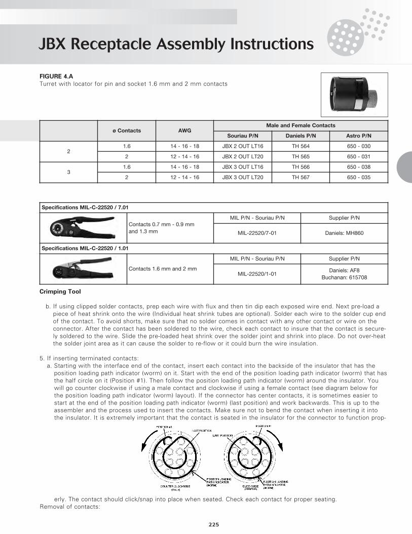
225
FIGURE 4.ATurret with locator for pin and socket 1.6 mm and 2 mm contacts
Crimping Tool
b. If using clipped solder contacts, prep each wire with flux and then tin dip each exposed wire end. Next pre-load apiece of heat shrink onto the wire (Individual heat shrink tubes are optional). Solder each wire to the solder cup endof the contact. To avoid shorts, make sure that no solder comes in contact with any other contact or wire on theconnector. After the contact has been soldered to the wire, check each contact to insure that the contact is secure-ly soldered to the wire. Slide the pre-loaded heat shrink over the solder joint and shrink into place. Do not over-heatthe solder joint area as it can cause the solder to re-flow or it could burn the wire insulation.
5. If inserting terminated contacts:a. Starting with the interface end of the contact, insert each contact into the backside of the insulator that has the
position loading path indicator (worm) on it. Start with the end of the position loading path indicator (worm) that hasthe half circle on it (Position #1). Then follow the position loading path indicator (worm) around the insulator. Youwill go counter clockwise if using a male contact and clockwise if using a female contact (see diagram below forthe position loading path indicator (worm) layout). If the connector has center contacts, it is sometimes easier tostart at the end of the position loading path indicator (worm) (last position) and work backwards. This is up to theassembler and the process used to insert the contacts. Make sure not to bend the contact when inserting it intothe insulator. It is extremely important that the contact is seated in the insulator for the connector to function prop-
erly. The contact should click/snap into place when seated. Check each contact for proper seating.Removal of contacts:
Shell Size ø Contacts AWGMale and Female Contacts
Souriau P/N Daniels P/N Astro P/N
21.6 14 - 16 - 18 JBX 2 OUT LT16 TH 564 650 - 030
2 12 - 14 - 16 JBX 2 OUT LT20 TH 565 650 - 031
31.6 14 - 16 - 18 JBX 3 OUT LT16 TH 566 650 - 038
2 12 - 14 - 16 JBX 3 OUT LT20 TH 567 650 - 035
Specifications MIL-C-22520 / 7.01
Contacts 0.7 mm - 0.9 mm
and 1.3 mm
MIL P/N - Souriau P/N Supplier P/N
MIL-22520/7-01 Daniels: MH860
Specifications MIL-C-22520 / 1.01
Contacts 1.6 mm and 2 mm
MIL P/N - Souriau P/N Supplier P/N
MIL-22520/1-01Daniels: AF8
Buchanan: 615708
JBX Receptacle Assembly Instructions
226
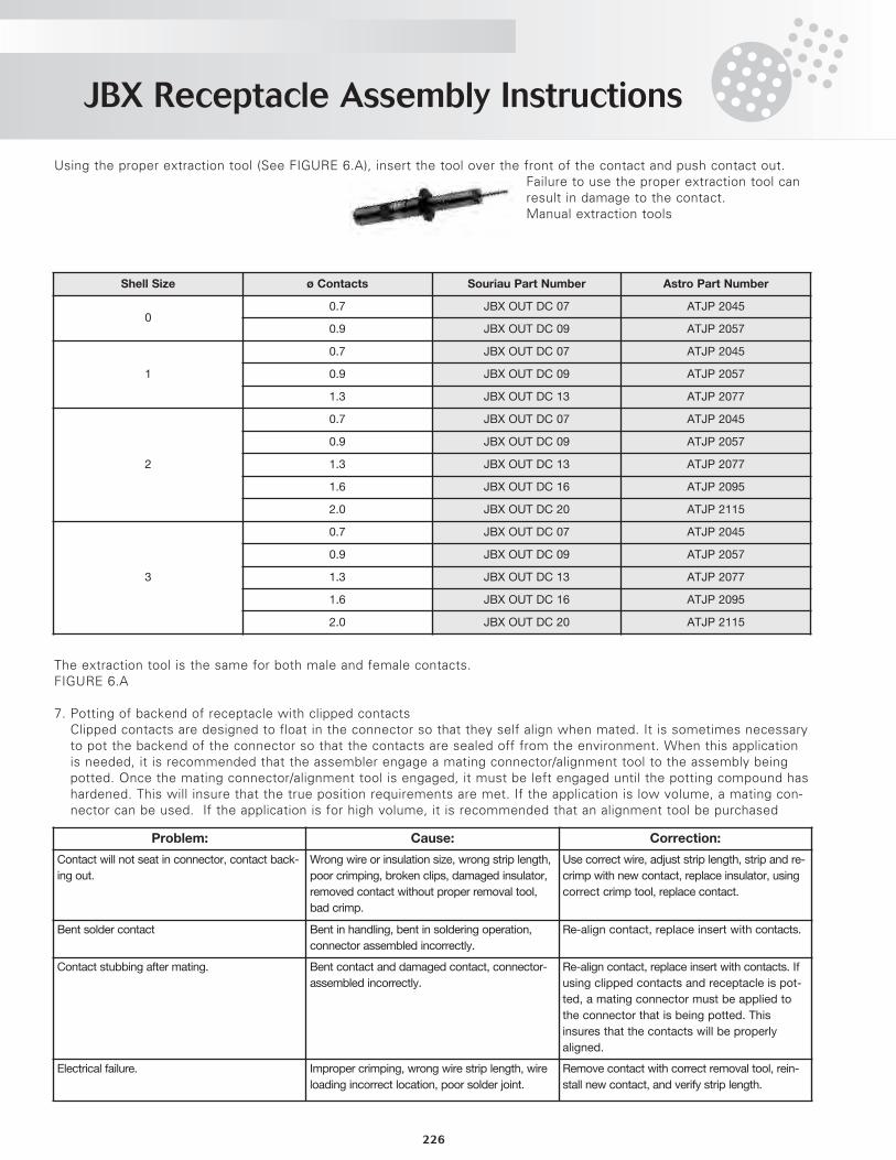
Using the proper extraction tool (See FIGURE 6.A), insert the tool over the front of the contact and push contact out.Failure to use the proper extraction tool canresult in damage to the contact. Manual extraction tools
The extraction tool is the same for both male and female contacts.FIGURE 6.A
7. Potting of backend of receptacle with clipped contactsClipped contacts are designed to float in the connector so that they self align when mated. It is sometimes necessaryto pot the backend of the connector so that the contacts are sealed off from the environment. When this applicationis needed, it is recommended that the assembler engage a mating connector/alignment tool to the assembly beingpotted. Once the mating connector/alignment tool is engaged, it must be left engaged until the potting compound hashardened. This will insure that the true position requirements are met. If the application is low volume, a mating con-nector can be used. If the application is for high volume, it is recommended that an alignment tool be purchased
Shell Size ø Contacts Souriau Part Number Astro Part Number
00.7 JBX OUT DC 07 ATJP 2045
0.9 JBX OUT DC 09 ATJP 2057
1
0.7 JBX OUT DC 07 ATJP 2045
0.9 JBX OUT DC 09 ATJP 2057
1.3 JBX OUT DC 13 ATJP 2077
2
0.7 JBX OUT DC 07 ATJP 2045
0.9 JBX OUT DC 09 ATJP 2057
1.3 JBX OUT DC 13 ATJP 2077
1.6 JBX OUT DC 16 ATJP 2095
2.0 JBX OUT DC 20 ATJP 2115
3
0.7 JBX OUT DC 07 ATJP 2045
0.9 JBX OUT DC 09 ATJP 2057
1.3 JBX OUT DC 13 ATJP 2077
1.6 JBX OUT DC 16 ATJP 2095
2.0 JBX OUT DC 20 ATJP 2115
Problem: Cause: Correction:
Contact will not seat in connector, contact back-
ing out.
Wrong wire or insulation size, wrong strip length,
poor crimping, broken clips, damaged insulator,
removed contact without proper removal tool,
bad crimp.
Use correct wire, adjust strip length, strip and re-
crimp with new contact, replace insulator, using
correct crimp tool, replace contact.
Bent solder contact Bent in handling, bent in soldering operation,
connector assembled incorrectly.
Re-align contact, replace insert with contacts.
Contact stubbing after mating. Bent contact and damaged contact, connector-
assembled incorrectly.
Re-align contact, replace insert with contacts. If
using clipped contacts and receptacle is pot-
ted, a mating connector must be applied to
the connector that is being potted. This
insures that the contacts will be properly
aligned.
Electrical failure. Improper crimping, wrong wire strip length, wire
loading incorrect location, poor solder joint.
Remove contact with correct removal tool, rein-
stall new contact, and verify strip length.
Environmentally Sealed Push Pull Connectors
227
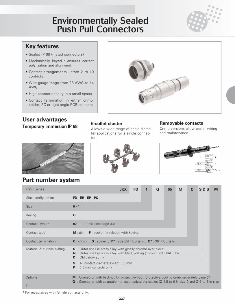
• Sealed IP 68 (mated connectors)
• Mechanically keyed : ensures correctpolarization and alignment.
• Contact arrangements : from 2 to 10contacts.
• Wire gauge range from 28 AWG to 14AWG.
• High contact density in a small space.
• Contact termination in either crimp,solder, PC or right angle PCB contacts.
Part number system
MS D SCM05G1FDJKXBasic series
Shell configuration FD - ER - EP - PC
Size 0 - 1
Keying G
Contact layouts 02 ---------- 10 (see page 33)
Contact type M : pin F : socket (in relation with keying)
Contact termination C : crimp ; S : solder ; P* : straight PCB tails ; Q* : 90° PCB tails
Material & surface plating S : Outer shell in brass alloy with glossy chrome over nickelN : Outer shell in brass alloy with black plating (consult SOURIAU US)D : Obligatory suffix
S : All contact diamete except 0.5 mmP : 0.5 mm contacts only
Options M : Connector with backnut for protective boot (protective boot to order separately page 34)G : Connector with adaptation to accomodate big cables (Ø 4.5 to 6 in size 0 and Ø 6 to 8 in size
1)
* For receptacles with female contacts only.
Key features
User advantagesTemporary immersion IP 68
6-collet clusterAllows a wide range of cable diame-ter applications for a single connec-tor.
Removable contactsCrimp versions allow easier wiringand maintenance.
Environmentally Sealed Push Pull Connectors
228
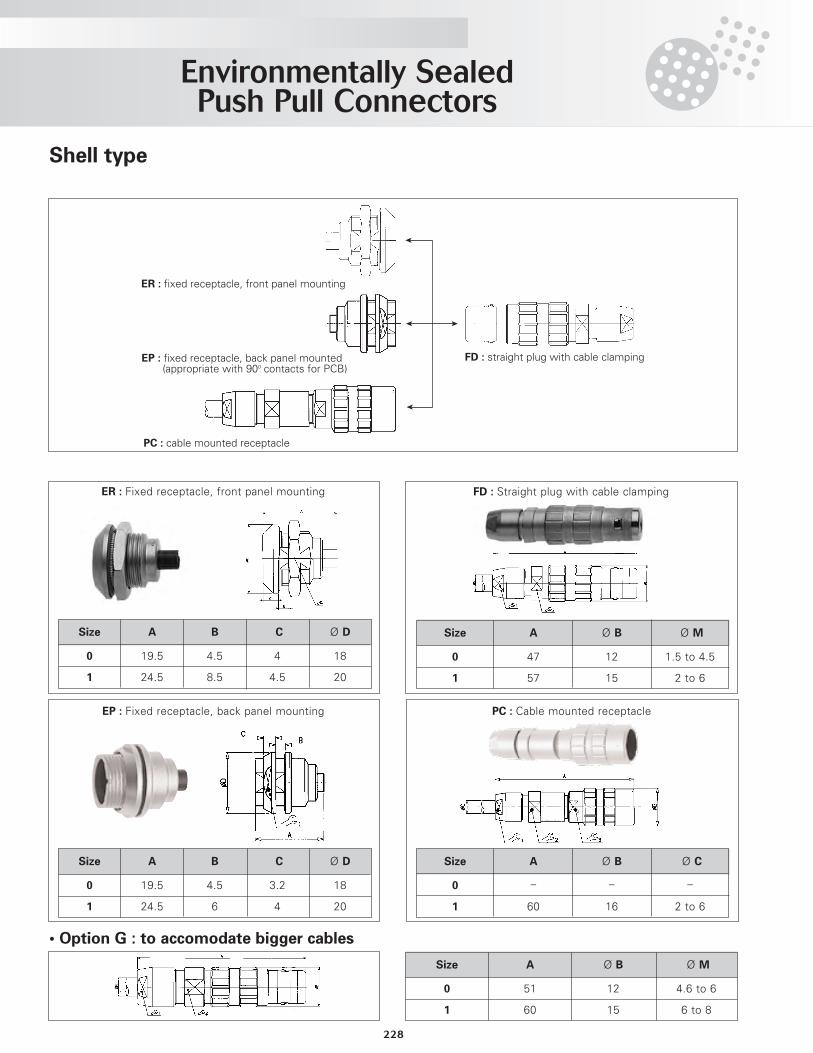
Shell type
ER : fixed receptacle, front panel mounting
EP : fixed receptacle, back panel mounted (appropriate with 900 contacts for PCB)
PC : cable mounted receptacle
FD : straight plug with cable clamping
FD : Straight plug with cable clamping
Size
0
1
A
47
57
Ø B
12
15
Ø M
1.5 to 4.5
2 to 6
ER : Fixed receptacle, front panel mounting
Size
0
1
A
19.5
24.5
B
4.5
8.5
C
4
4.5
Ø D
18
20
EP : Fixed receptacle, back panel mounting
Size
0
1
A
19.5
24.5
B
4.5
6
C
3.2
4
Ø D
18
20
PC : Cable mounted receptacle
• Option G : to accomodate bigger cables
Size
0
1
A
51
60
Ø B
12
15
Ø M
4.6 to 6
6 to 8
Size
0
1
A
_
60
Ø B
_
16
Ø C
_
2 to 6
Environmentally Sealed Push Pull Connectors
229
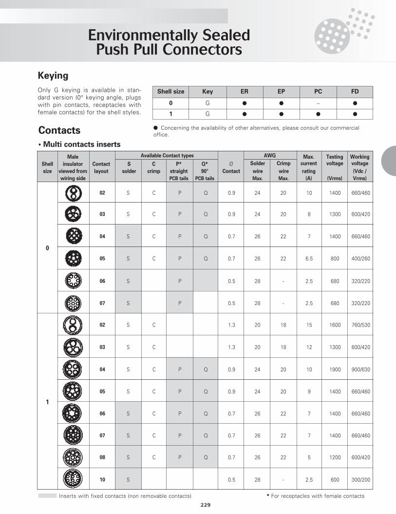
Keying
Contacts
• Multi contacts inserts
Only G keying is available in stan-dard version (0° keying angle, plugswith pin contacts, receptacles withfemale contacts) for the shell styles.
Shell size Key ER EP PC FD
0 G l l _ l
1 G l l l l
l Concerning the availability of other alternatives, please consult our commercialoffice.
Male AWG Max. Testing Working
Shell insulator Contact S C P* Q* Ø Solder Crimp current voltage voltage
size viewed from layout solder crimp straight 90° Contact wire wire rating (Vdc /
wiring side PCB tails PCB tails Max. Max. (A) (Vrms) Vrms)
02 S C P Q 0.9 24 20 10 1400 660/460
03 S C P Q 0.9 24 20 8 1300 600/420
04 S C P Q 0.7 26 22 7 1400 660/460
05 S C P Q 0.7 26 22 6.5 800 400/260
06 S P 0.5 28 - 2.5 680 320/220
07 S P 0.5 28 - 2.5 680 320/220
02 S C 1.3 20 18 15 1600 760/530
03 S C 1.3 20 18 12 1300 600/420
04 S C P Q 0.9 24 20 10 1900 900/630
05 S C P Q 0.9 24 20 9 1400 660/460
06 S C P Q 0.7 26 22 7 1400 660/460
07 S C P Q 0.7 26 22 7 1400 660/460
08 S C P Q 0.7 26 22 5 1200 600/420
10 S 0.5 28 - 2.5 600 300/200
Inserts with fixed contacts (non removable contacts) * For receptacles with female contacts
Available Contact types
0
1
Environmentally Sealed Push Pull Connectors
230
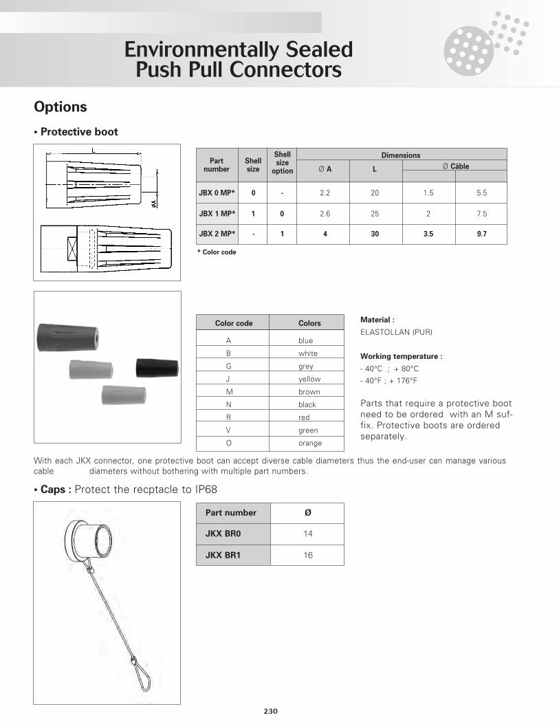
Options
• Protective boot
• Caps : Protect the recptacle to IP68
With each JKX connector, one protective boot can accept diverse cable diameters thus the end-user can manage variouscable diameters without bothering with multiple part numbers.
Material :
ELASTOLLAN (PUR)
Working temperature :
- 40°C ; + 80°C
- 40°F ; + 176°F
Shell DimensionsPart Shell size
number size option Ø A L Ø Câble
JBX 1 MP* 1 0 2.6 25 2 7.5
JBX 2 MP* - 1 4 30 3.5 9.7
Color code Colors
A blue
B white
G grey
J yellow
M brown
N black
R red
V green
O orange
* Color code
Part number Ø
JKX BR0 14
JKX BR1 16
Parts that require a protective bootneed to be ordered with an M suf-fix. Protective boots are orderedseparately.
JBX 0 MP* 0 - 2.2 20 1.5 5.5
Environmentally Sealed Push Pull Connectors
231
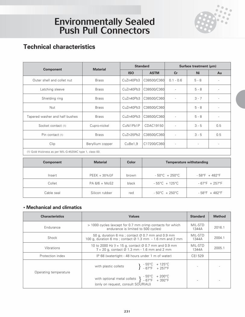
Technical characteristics
• Mechanical and climatics
Component MaterialStandard Surface treatment (µm)
ISO ASTM Cr Ni Au
Outer shell and collet nut Brass CuZn40Pb3 C38500/C360 0.1 - 0.6 5 - 8 -
Latching sleeve Brass CuZn40Pb3 C38500/C360 - 5 - 8 -
Shielding ring Brass CuZn40Pb3 C38500/C360 - 3 - 7 -
Nut Brass CuZn40Pb3 C38500/C360 5 - 8 -
Tapered washer and half bushes Brass CuZn40Pb3 C38500/C360 - 5 - 8 -
Socket contact (1) Cupro-nickel CuNi1Pb1P CDAC19150 - 3 - 5 0.5
Pin contact (1) Brass CuZn35Pb2 C38500/C360 - 3 - 5 0.5
Clip Beryllium copper CuBe1,9 C17200/C360 - - -
Component Material Color Temperature withstanding
Insert PEEK + 30%GF brown - 50°C + 250°C - 58°F + 482°F
Collet PA 6/6 + MoS2 black - 55°C + 125°C - 67°F + 257°F
Cable seal Silicon rubber red - 50°C + 250°C - 58°F + 482°F
Characteristics Values Standard Method
Endurance> 1000 cycles (except for 0.7 mm crimp contacts for which MIL-STD
2016.1endurance is limited to 500 cycles) 1344A
Shock50 g, duration 6 ms ; contact Ø 0.7 mm and 0.9 mm MIL-STD
2004.1100 g, duration 6 ms ; contact Ø 1.3 mm - 1.6 mm and 2 mm 1344A
Vibrations10 to 2000 Hz γ = 15 g, contact Ø 0.7 mm and 0.9 mm MIL-STD
2005.1γ = 20 g, contact Ø 1.3 mm - 1.6 mm and 2 mm 1344A
Protection index IP 68 (watertight - 48 hours under 1 m of water) CEI 529
- 55°C + 125°Cwith plastic collets
- 67°F + 257°F- -
Operating temperature
with optional metal collets- 55°C + 200°C- 67°F + 392°F - -
(only on request, consult SOURIAU)
(1) Gold thickness as per MIL-G-45204C type 1, class 00.
}
}
Environmentally Sealed Push Pull Connectors
232
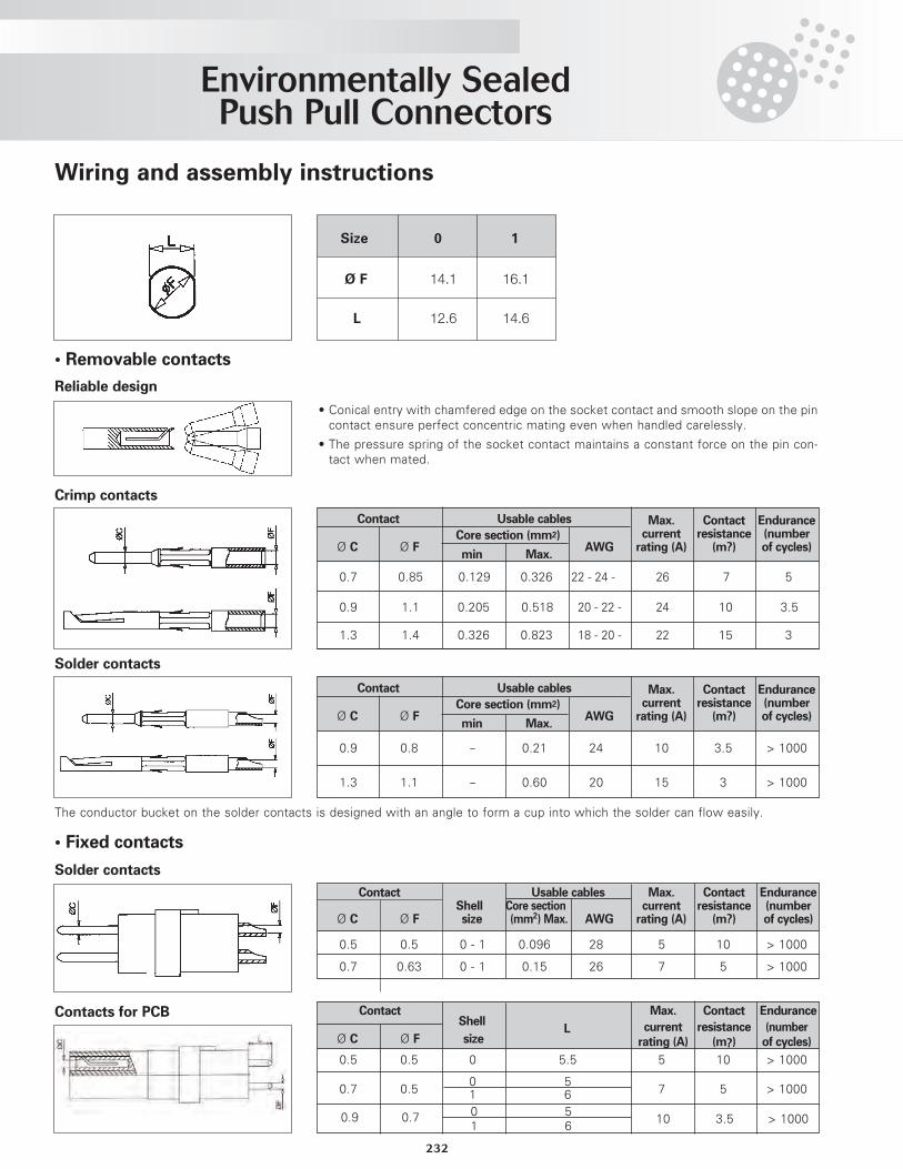
Wiring and assembly instructions
• Removable contacts
Reliable design
Crimp contacts
Solder contacts
• Conical entry with chamfered edge on the socket contact and smooth slope on the pincontact ensure perfect concentric mating even when handled carelessly.
• The pressure spring of the socket contact maintains a constant force on the pin con-tact when mated.
Contact Usable cables Max. Contact EnduranceCore section (mm2) current resistance (number
Ø C Ø F AWG rating (A) (m?) of cycles)min Max.
0.7 0.85 0.129 0.326 22 - 24 - 26 7 5
0.9 1.1 0.205 0.518 20 - 22 - 24 10 3.5
1.3 1.4 0.326 0.823 18 - 20 - 22 15 3
Contact Usable cables Max. Contact EnduranceCore section (mm2) current resistance (number
Ø C Ø F AWG rating (A) (m?) of cycles)min Max.
0.9 0.8 - 0.21 24 10 3.5 > 1000
1.3 1.1 - 0.60 20 15 3 > 1000
The conductor bucket on the solder contacts is designed with an angle to form a cup into which the solder can flow easily.
• Fixed contacts
Solder contacts
Contact Usable cables Max. Contact EnduranceShell Core section current resistance (number
Ø C Ø F size (mm2) Max. AWG rating (A) (m?) of cycles)
0.5 0.5 0 - 1 0.096 28 5 10 > 1000
0.7 0.63 0 - 1 0.15 26 7 5 > 1000
Contacts for PCB Contact Max. Contact EnduranceShell current resistance (number
Ø C Ø F sizeL
rating (A) (m?) of cycles)
0.7 0.50 5
7 5 > 10001 6
0.5 0.5 0 5.5 5 10 > 1000
0.9 0.7 0 510 3.5 > 10001 6
Size 0 1
Ø F 14.1 16.1
L 12.6 14.6
Environmentally Sealed Push Pull Connectors
233
? 1.35
> 1.35
? 1.6
> 1.6
? 1.35
> 1.35
? 1.6
> 1.6
? 2.1
> 2.1
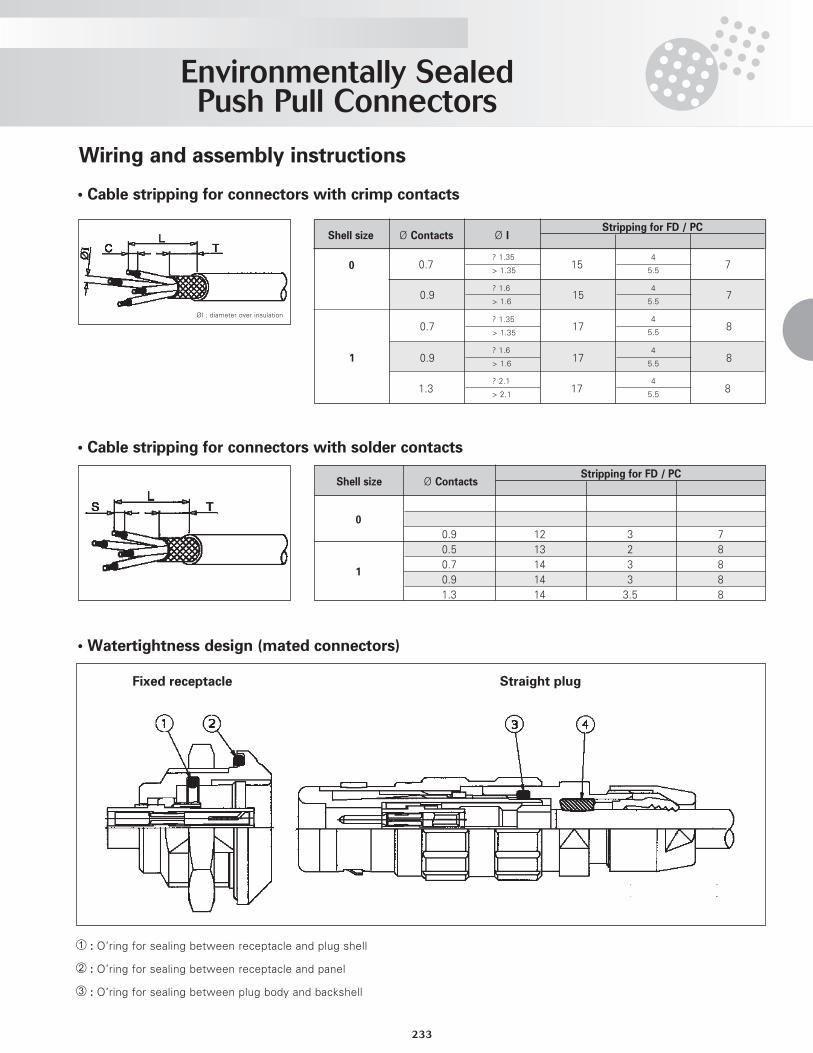
Wiring and assembly instructions
• Cable stripping for connectors with crimp contacts
• Cable stripping for connectors with solder contacts
Stripping for FD / PC
0.7 15 7
0.9 15 7
0.7 17 8
1 0.9 17 8
1.3 17 8
Shell size Ø Contacts Ø I
Shell size Ø Contacts
0
1
04
5.5
4
5.5
4
5.5
4
5.5
4
5.5
Stripping for FD / PC
0.9 12 3 70.5 13 2 80.7 14 3 80.9 14 3 81.3 14 3.5 8
ØI : diameter over insulation
¿ : O’ring for sealing between receptacle and plug shell
¡ : O’ring for sealing between receptacle and panel
¬ : O’ring for sealing between plug body and backshell
Fixed receptacle Straight plug
• Watertightness design (mated connectors)
Environmentally Sealed Push Pull Connectors
234
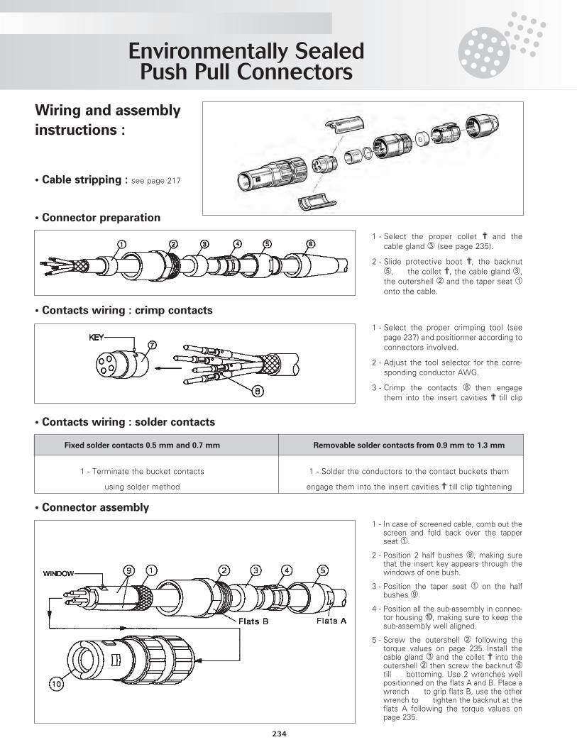
• Connector preparation
1 - Select the proper collet ? and thecable gland ¬ (see page 235).
2 - Slide protective boot ?, the backnutƒ, the collet ?, the cable gland ¬,the outershell ¡ and the taper seat ¿onto the cable.
• Contacts wiring : crimp contacts
1 - Select the proper crimping tool (seepage 237) and positionner according toconnectors involved.
2 - Adjust the tool selector for the corre-sponding conductor AWG.
3 - Crimp the contacts « then engagethem into the insert cavities ? till clip
• Contacts wiring : solder contacts
Fixed solder contacts 0.5 mm and 0.7 mm Removable solder contacts from 0.9 mm to 1.3 mm
1 - Terminate the bucket contacts 1 - Solder the conductors to the contact buckets them
using solder method engage them into the insert cavities ? till clip tightening
• Connector assembly
1 - In case of screened cable, comb out thescreen and fold back over the tapperseat ¿.
2 - Position 2 half bushes », making surethat the insert key appears through thewindows of one bush.
3 - Position the taper seat ¿ on the halfbushes ».
4 - Position all the sub-assembly in connec-tor housing …, making sure to keep thesub-assembly well aligned.
5 - Screw the outershell ¡ following thetorque values on page 235. Install thecable gland ¬ and the collet ? into theoutershell ¡ then screw the backnut ƒtill bottoming. Use 2 wrenches wellpositionned on the flats A and B. Place awrench to grip flats B, use the otherwrench to tighten the backnut at theflats A following the torque values onpage 235.
Wiring and assembly
instructions :
• Cable stripping : see page 217
Environmentally Sealed Push Pull Connectors
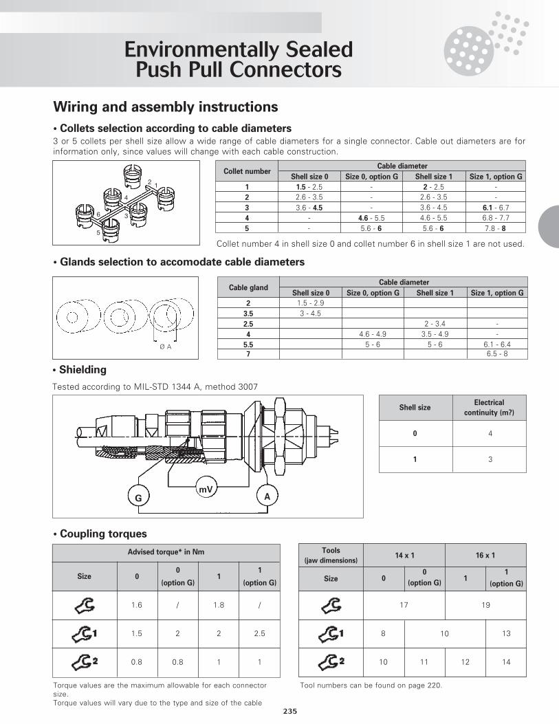
235
• Collets selection according to cable diameters3 or 5 collets per shell size allow a wide range of cable diameters for a single connector. Cable out diameters are forinformation only, since values will change with each cable construction.
Cable diameter
Shell size 0 Size 0, option G Shell size 1 Size 1, option G
1 1.5 - 2.5 - 2 - 2.5 -2 2.6 - 3.5 - 2.6 - 3.5 -3 3.6 - 4.5 - 3.6 - 4.5 6.1 - 6.74 - 4.6 - 5.5 4.6 - 5.5 6.8 - 7.75 - 5.6 - 6 5.6 - 6 7.8 - 8
Collet number 4 in shell size 0 and collet number 6 in shell size 1 are not used.
• Glands selection to accomodate cable diameters
Collet number
Cable diameter
Shell size 0 Size 0, option G Shell size 1 Size 1, option G
2 1.5 - 2.93.5 3 - 4.52.5 2 - 3.4 -4 4.6 - 4.9 3.5 - 4.9 -
5.5 5 - 6 5 - 6 6.1 - 6.47 6.5 - 8
Cable gland
2
4
3
5
6
1
Advised torque* in Nm
00
(option G)1
1
(option G)
1.6 / 1.8 /
1.5 2.5
0.8 1
2 2
0.8 1
Size
14 x 1 16 x 1
00
(option G)1
1
(option G)
17
8 13
10 11 12 14
19
10
Size
Tools
(jaw dimensions)
Wiring and assembly instructions
• Coupling torques
Torque values are the maximum allowable for each connectorsize.Torque values will vary due to the type and size of the cable
Tool numbers can be found on page 220.
• Shielding
Tested according to MIL-STD 1344 A, method 3007
Shell size
0 4
1 3
G AmV
Ø A
Electrical
continuity (m?)
JKX Plug Assembly Instructions
236
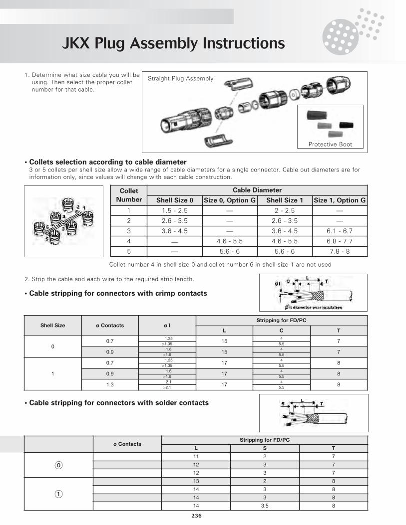
1. Determine what size cable you will beusing. Then select the proper colletnumber for that cable.
• Collets selection according to cable diameter3 or 5 collets per shell size allow a wide range of cable diameters for a single connector. Cable out diameters are forinformation only, since values will change with each cable construction.
Collet number 4 in shell size 0 and collet number 6 in shell size 1 are not used
2. Strip the cable and each wire to the required strip length.
• Cable stripping for connectors with crimp contacts
• Cable stripping for connectors with solder contacts
Collet
Number
Cable Diameter
Shell Size 0 Size 0, Option G Shell Size 1 Size 1, Option G
1 1.5 - 2.5 — 2 - 2.5 —
2 2.6 - 3.5 — 2.6 - 3.5 —
3 3.6 - 4.5 — 3.6 - 4.5 6.1 - 6.7
4 — 4.6 - 5.5 4.6 - 5.5 6.8 - 7.7
5 — 5.6 - 6 5.6 - 6 7.8 - 8
Shell Size ø Contacts ø IStripping for FD/PC
L C T
00.7
≤1.3515
47
>1.35 5.5
0.9≤1.6
154
7>1.6 5.5
1
0.7≤1.35
174
8>1.35 5.5
0.9≤1.6
174
8>1.6 5.5
1.3≤2.1
174
8>2.1 5.5
Straight Plug Assembly
Protective Boot
Shell Size ø ContactsStripping for FD/PC
L S T
011 2 7
12 3 7
12 3 7
1
13 2 8
14 3 8
14 3 8
14 3.5 8
JKX Plug Assembly Instructions
237
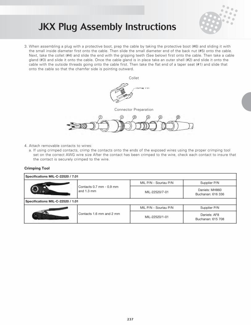
3. When assembling a plug with a protective boot, prep the cable by taking the protective boot (#6) and sliding it withthe small inside diameter first onto the cable. Then slide the small diameter end of the back nut (#5) onto the cable.Next, take the collet (#4) and slide the end with the gripping teeth (See below) first onto the cable. Then take a cablegland (#3) and slide it onto the cable. Once the cable gland is in place take an outer shell (#2) and slide it onto thecable with the outside threads going onto the cable first. Then take the flat end of a taper seat (#1) and slide thatonto the cable so that the chamfer side is pointing outward.
Collet
Connector Preparation
4. Attach removable contacts to wires:a. If using crimped contacts, crimp the contacts onto the ends of the exposed wires using the proper crimping tool
set on the correct AWG wire size After the contact has been crimped to the wire, check each contact to insure thatthe contact is securely crimped to the wire.
Crimping Tool
Specifications MIL-C-22520 / 7.01
Contacts 0.7 mm - 0.9 mm
and 1.3 mm
MIL P/N - Souriau P/N Supplier P/N
MIL-22520/7-01Daniels: MH860
Buchanan: 616 336
Specifications MIL-C-22520 / 1.01
Contacts 1.6 mm and 2 mm
MIL P/N - Souriau P/N Supplier P/N
MIL-22520/1-01Daniels: AF8
Buchanan: 615 708
JKX Plug Assembly Instructions
238
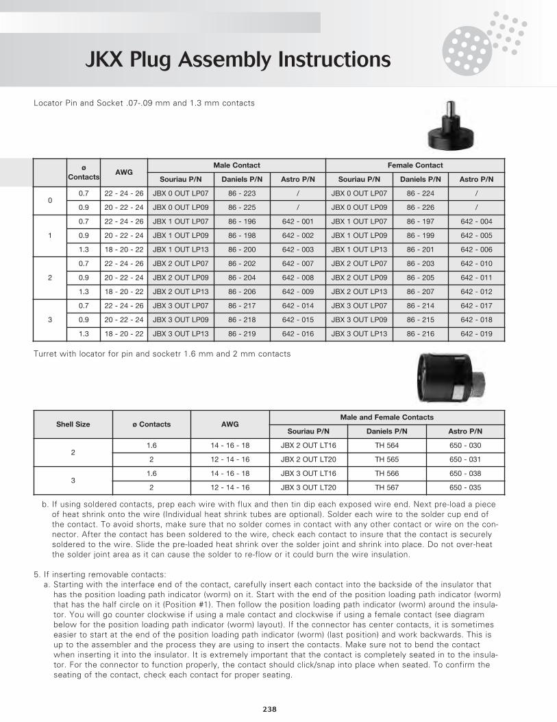
Locator Pin and Socket .07-.09 mm and 1.3 mm contacts
Turret with locator for pin and socketr 1.6 mm and 2 mm contacts
b. If using soldered contacts, prep each wire with flux and then tin dip each exposed wire end. Next pre-load a pieceof heat shrink onto the wire (Individual heat shrink tubes are optional). Solder each wire to the solder cup end ofthe contact. To avoid shorts, make sure that no solder comes in contact with any other contact or wire on the con-nector. After the contact has been soldered to the wire, check each contact to insure that the contact is securelysoldered to the wire. Slide the pre-loaded heat shrink over the solder joint and shrink into place. Do not over-heatthe solder joint area as it can cause the solder to re-flow or it could burn the wire insulation.
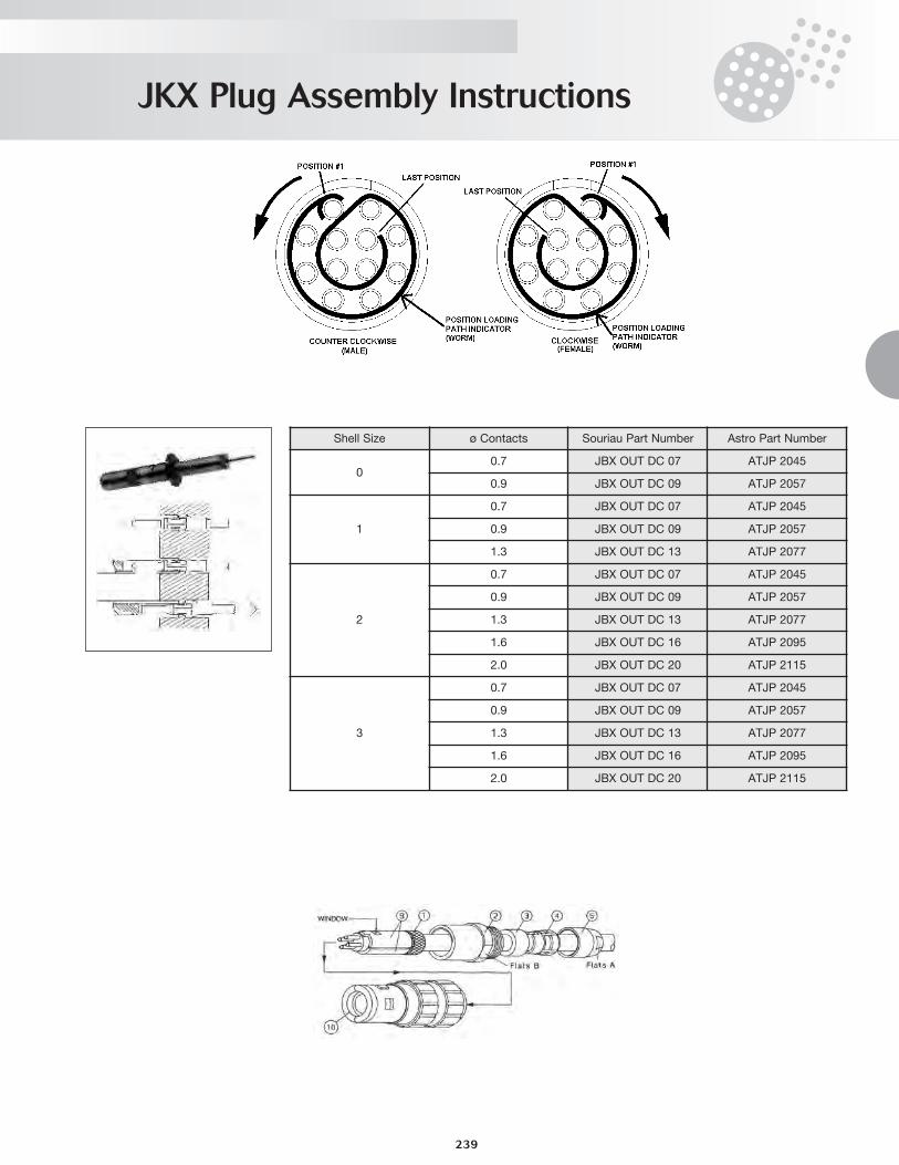
5. If inserting removable contacts:a. Starting with the interface end of the contact, carefully insert each contact into the backside of the insulator that
has the position loading path indicator (worm) on it. Start with the end of the position loading path indicator (worm)that has the half circle on it (Position #1). Then follow the position loading path indicator (worm) around the insula-tor. You will go counter clockwise if using a male contact and clockwise if using a female contact (see diagrambelow for the position loading path indicator (worm) layout). If the connector has center contacts, it is sometimeseasier to start at the end of the position loading path indicator (worm) (last position) and work backwards. This isup to the assembler and the process they are using to insert the contacts. Make sure not to bend the contactwhen inserting it into the insulator. It is extremely important that the contact is completely seated in to the insula-tor. For the connector to function properly, the contact should click/snap into place when seated. To confirm theseating of the contact, check each contact for proper seating.
Shell
Size
ø
ContactsAWG
Male Contact Female Contact
Souriau P/N Daniels P/N Astro P/N Souriau P/N Daniels P/N Astro P/N
00.7 22 - 24 - 26 JBX 0 OUT LP07 86 - 223 / JBX 0 OUT LP07 86 - 224 /
0.9 20 - 22 - 24 JBX 0 OUT LP09 86 - 225 / JBX 0 OUT LP09 86 - 226 /
1
0.7 22 - 24 - 26 JBX 1 OUT LP07 86 - 196 642 - 001 JBX 1 OUT LP07 86 - 197 642 - 004
0.9 20 - 22 - 24 JBX 1 OUT LP09 86 - 198 642 - 002 JBX 1 OUT LP09 86 - 199 642 - 005
1.3 18 - 20 - 22 JBX 1 OUT LP13 86 - 200 642 - 003 JBX 1 OUT LP13 86 - 201 642 - 006
2
0.7 22 - 24 - 26 JBX 2 OUT LP07 86 - 202 642 - 007 JBX 2 OUT LP07 86 - 203 642 - 010
0.9 20 - 22 - 24 JBX 2 OUT LP09 86 - 204 642 - 008 JBX 2 OUT LP09 86 - 205 642 - 011
1.3 18 - 20 - 22 JBX 2 OUT LP13 86 - 206 642 - 009 JBX 2 OUT LP13 86 - 207 642 - 012
3
0.7 22 - 24 - 26 JBX 3 OUT LP07 86 - 217 642 - 014 JBX 3 OUT LP07 86 - 214 642 - 017
0.9 20 - 22 - 24 JBX 3 OUT LP09 86 - 218 642 - 015 JBX 3 OUT LP09 86 - 215 642 - 018
1.3 18 - 20 - 22 JBX 3 OUT LP13 86 - 219 642 - 016 JBX 3 OUT LP13 86 - 216 642 - 019
Shell Size ø Contacts AWGMale and Female Contacts
Souriau P/N Daniels P/N Astro P/N
21.6 14 - 16 - 18 JBX 2 OUT LT16 TH 564 650 - 030
2 12 - 14 - 16 JBX 2 OUT LT20 TH 565 650 - 031
31.6 14 - 16 - 18 JBX 3 OUT LT16 TH 566 650 - 038
2 12 - 14 - 16 JBX 3 OUT LT20 TH 567 650 - 035
JKX Plug Assembly Instructions
239
Shell Size ø Contacts Souriau Part Number Astro Part Number
00.7 JBX OUT DC 07 ATJP 2045
0.9 JBX OUT DC 09 ATJP 2057
1
0.7 JBX OUT DC 07 ATJP 2045
0.9 JBX OUT DC 09 ATJP 2057
1.3 JBX OUT DC 13 ATJP 2077
2
0.7 JBX OUT DC 07 ATJP 2045
0.9 JBX OUT DC 09 ATJP 2057
1.3 JBX OUT DC 13 ATJP 2077
1.6 JBX OUT DC 16 ATJP 2095
2.0 JBX OUT DC 20 ATJP 2115
3
0.7 JBX OUT DC 07 ATJP 2045
0.9 JBX OUT DC 09 ATJP 2057
1.3 JBX OUT DC 13 ATJP 2077
1.6 JBX OUT DC 16 ATJP 2095
2.0 JBX OUT DC 20 ATJP 2115
JKX Plug Assembly Instructions
240
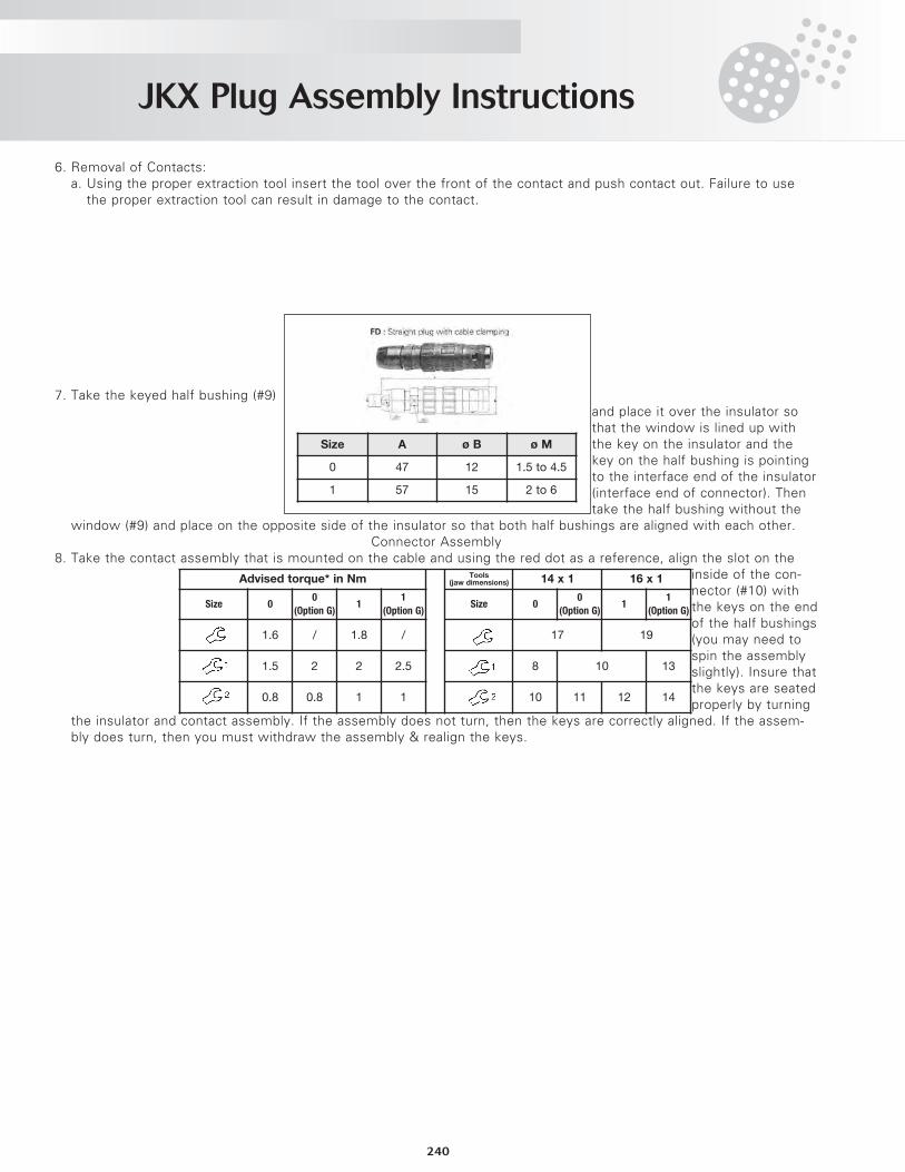
6. Removal of Contacts:a. Using the proper extraction tool insert the tool over the front of the contact and push contact out. Failure to use
the proper extraction tool can result in damage to the contact.
7. Take the keyed half bushing (#9)and place it over the insulator sothat the window is lined up withthe key on the insulator and thekey on the half bushing is pointingto the interface end of the insulator(interface end of connector). Thentake the half bushing without the
window (#9) and place on the opposite side of the insulator so that both half bushings are aligned with each other.Connector Assembly
8. Take the contact assembly that is mounted on the cable and using the red dot as a reference, align the slot on theinside of the con-nector (#10) withthe keys on the endof the half bushings(you may need tospin the assemblyslightly). Insure thatthe keys are seatedproperly by turning
the insulator and contact assembly. If the assembly does not turn, then the keys are correctly aligned. If the assem-bly does turn, then you must withdraw the assembly & realign the keys.
Size A ø B ø M
0 47 12 1.5 to 4.5
1 57 15 2 to 6
Advised torque* in Nm Tools(jaw dimensions) 14 x 1 16 x 1
Size 00
(Option�G)1
1
(Option�G)Size 0
0
(Option�G)1
1
(Option�G)
1.6 / 1.8 / 17 19
1.5 2 2 2.5 8 10 13
0.8 0.8 1 1 10 11 12 14
JKX Plug Assembly Instructions
241
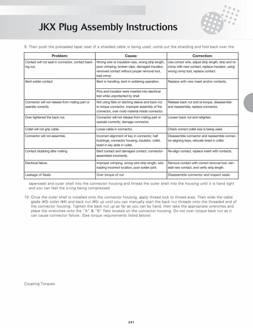
9. Then push the preloaded taper seat (if a shielded cable is being used, comb out the shielding and fold back over the
taperseat) and outer shell into the connector housing and thread the outer shell into the housing until it is hand tightand you can feel the o-ring being compressed.
10. Once the outer shell is installed onto the connector housing, apply thread lock to thread area. Then slide the cableglade (#3) collet (#4) and back nut (#5) up until you can manually start the back nut threads onto the threaded end ofthe connector housing. Tighten the back nut up as far as you can by hand, then take the appropriate wrenches andplace the wrenches onto the “A” & “B” flats located on the connector housing. Do not over torque back nut as itcan cause connector failure. (See torque requirements listed below)
Coupling Torques
Problem: Cause: Correction:
Contact will not seat in connector, contact back-
ing out.
Wrong wire or insulation size, wrong strip length,
poor crimping, broken clips, damaged insulator,
removed contact without proper removal tool,
bad crimp.
Use correct wire, adjust strip length, strip and re-
crimp with new contact, replace insulator, using
wrong crimp tool, replace contact.
Bent solder contact Bent in handling, bent in soldering operation, Replace with new insert and/or contacts.
Pins and insulator were inserted into electrical
test while unprotected by shell
Connector will not release from mating part or
operate correctly
Not using flats on latching sleeve and back nut
to torque connector, improper assembly of the
connector, over mold material inside connector.
Release back nut and re-torque, disassemble
and reassemble, replace connector.
Over tightened the back nut. Connector will not release from mating part or
operate correctly, damage connector.
Loosen back nut and retighten.
Collet will not grip cable. Loose cable in connector. Check correct collet size is being used.
Connector will not assemble. Incorrect alignment of key in connector, half
bushings, connector housing, insulator, collet,
braid in key slots in collet.
Disassemble connector and reassemble connec-
tor-aligning keys, relocate braid in collet.
Contact stubbing after mating. Bent contact and damaged contact, connector-
assembled incorrectly.
Re-align contact, replace insert with contacts.
Electrical failure. Improper crimping, wrong wire strip length, wire
loading incorrect location, poor solder joint.
Remove contact with correct removal tool, rein-
stall new contact, and verify strip length.
Leakage of Seals Over torque of nut Disassemble connector and inspect seals
JKX Receptacle Assembly Instructions
242
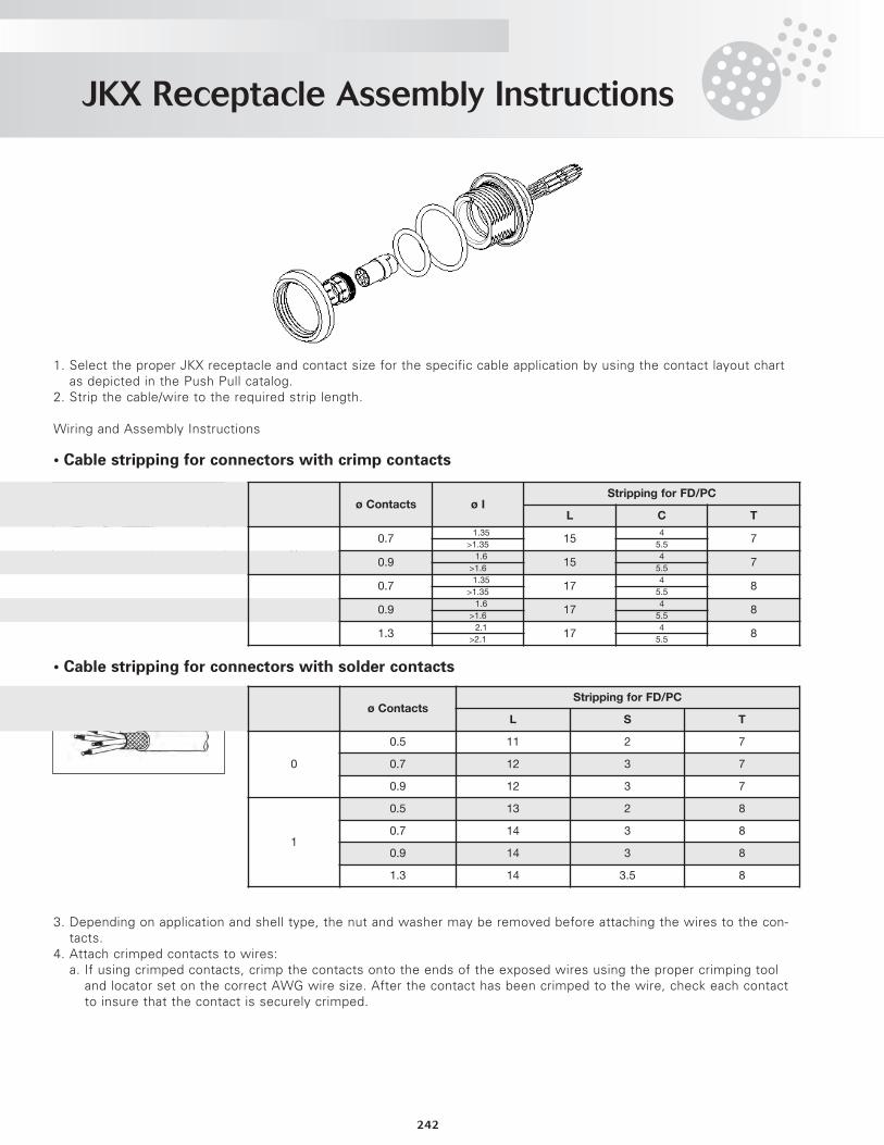
1. Select the proper JKX receptacle and contact size for the specific cable application by using the contact layout chartas depicted in the Push Pull catalog.
2. Strip the cable/wire to the required strip length.
Wiring and Assembly Instructions
• Cable stripping for connectors with crimp contacts
• Cable stripping for connectors with solder contacts
3. Depending on application and shell type, the nut and washer may be removed before attaching the wires to the con-tacts.
4. Attach crimped contacts to wires:a. If using crimped contacts, crimp the contacts onto the ends of the exposed wires using the proper crimping tool
and locator set on the correct AWG wire size. After the contact has been crimped to the wire, check each contactto insure that the contact is securely crimped.
Shell Size ø Contacts ø IStripping for FD/PC
L C T
00.7
≤1.3515
47
>1.35 5.5
0.9≤1.6
154
7>1.6 5.5
1
0.7≤1.35
174
8>1.35 5.5
0.9≤1.6
174
8>1.6 5.5
1.3≤2.1
174
8>2.1 5.5
Shell Size ø ContactsStripping for FD/PC
L S T
0
0.5 11 2 7
0.7 12 3 7
0.9 12 3 7
1
0.5 13 2 8
0.7 14 3 8
0.9 14 3 8
1.3 14 3.5 8
JKX Receptacle Assembly Instructions
243
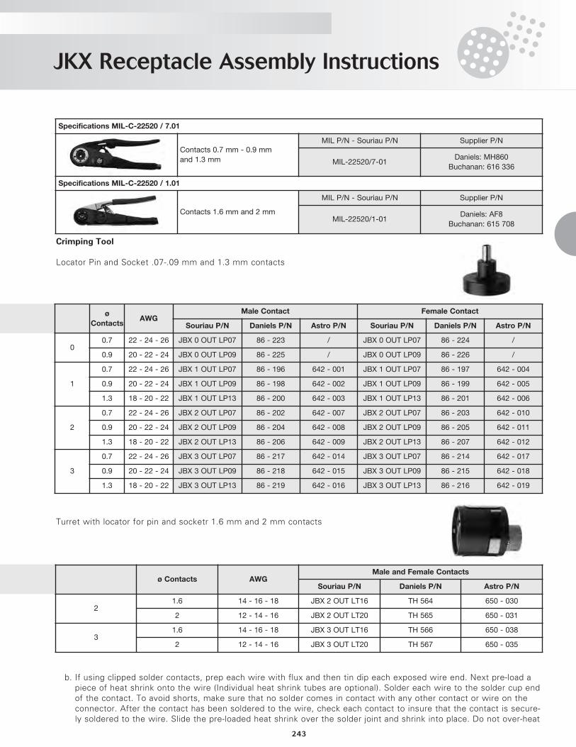
Crimping Tool
Locator Pin and Socket .07-.09 mm and 1.3 mm contacts
Turret with locator for pin and socketr 1.6 mm and 2 mm contacts
b. If using clipped solder contacts, prep each wire with flux and then tin dip each exposed wire end. Next pre-load apiece of heat shrink onto the wire (Individual heat shrink tubes are optional). Solder each wire to the solder cup endof the contact. To avoid shorts, make sure that no solder comes in contact with any other contact or wire on theconnector. After the contact has been soldered to the wire, check each contact to insure that the contact is secure-ly soldered to the wire. Slide the pre-loaded heat shrink over the solder joint and shrink into place. Do not over-heat
Specifications MIL-C-22520 / 7.01
Contacts 0.7 mm - 0.9 mm
and 1.3 mm
MIL P/N - Souriau P/N Supplier P/N
MIL-22520/7-01Daniels: MH860
Buchanan: 616 336
Specifications MIL-C-22520 / 1.01
Contacts 1.6 mm and 2 mm
MIL P/N - Souriau P/N Supplier P/N
MIL-22520/1-01Daniels: AF8
Buchanan: 615 708
Shell
Size
ø
ContactsAWG
Male Contact Female Contact
Souriau P/N Daniels P/N Astro P/N Souriau P/N Daniels P/N Astro P/N
00.7 22 - 24 - 26 JBX 0 OUT LP07 86 - 223 / JBX 0 OUT LP07 86 - 224 /
0.9 20 - 22 - 24 JBX 0 OUT LP09 86 - 225 / JBX 0 OUT LP09 86 - 226 /
1
0.7 22 - 24 - 26 JBX 1 OUT LP07 86 - 196 642 - 001 JBX 1 OUT LP07 86 - 197 642 - 004
0.9 20 - 22 - 24 JBX 1 OUT LP09 86 - 198 642 - 002 JBX 1 OUT LP09 86 - 199 642 - 005
1.3 18 - 20 - 22 JBX 1 OUT LP13 86 - 200 642 - 003 JBX 1 OUT LP13 86 - 201 642 - 006
2
0.7 22 - 24 - 26 JBX 2 OUT LP07 86 - 202 642 - 007 JBX 2 OUT LP07 86 - 203 642 - 010
0.9 20 - 22 - 24 JBX 2 OUT LP09 86 - 204 642 - 008 JBX 2 OUT LP09 86 - 205 642 - 011
1.3 18 - 20 - 22 JBX 2 OUT LP13 86 - 206 642 - 009 JBX 2 OUT LP13 86 - 207 642 - 012
3
0.7 22 - 24 - 26 JBX 3 OUT LP07 86 - 217 642 - 014 JBX 3 OUT LP07 86 - 214 642 - 017
0.9 20 - 22 - 24 JBX 3 OUT LP09 86 - 218 642 - 015 JBX 3 OUT LP09 86 - 215 642 - 018
1.3 18 - 20 - 22 JBX 3 OUT LP13 86 - 219 642 - 016 JBX 3 OUT LP13 86 - 216 642 - 019
Shell Size ø Contacts AWGMale and Female Contacts
Souriau P/N Daniels P/N Astro P/N
21.6 14 - 16 - 18 JBX 2 OUT LT16 TH 564 650 - 030
2 12 - 14 - 16 JBX 2 OUT LT20 TH 565 650 - 031
31.6 14 - 16 - 18 JBX 3 OUT LT16 TH 566 650 - 038
2 12 - 14 - 16 JBX 3 OUT LT20 TH 567 650 - 035
JKX Receptacle Assembly Instructions
244
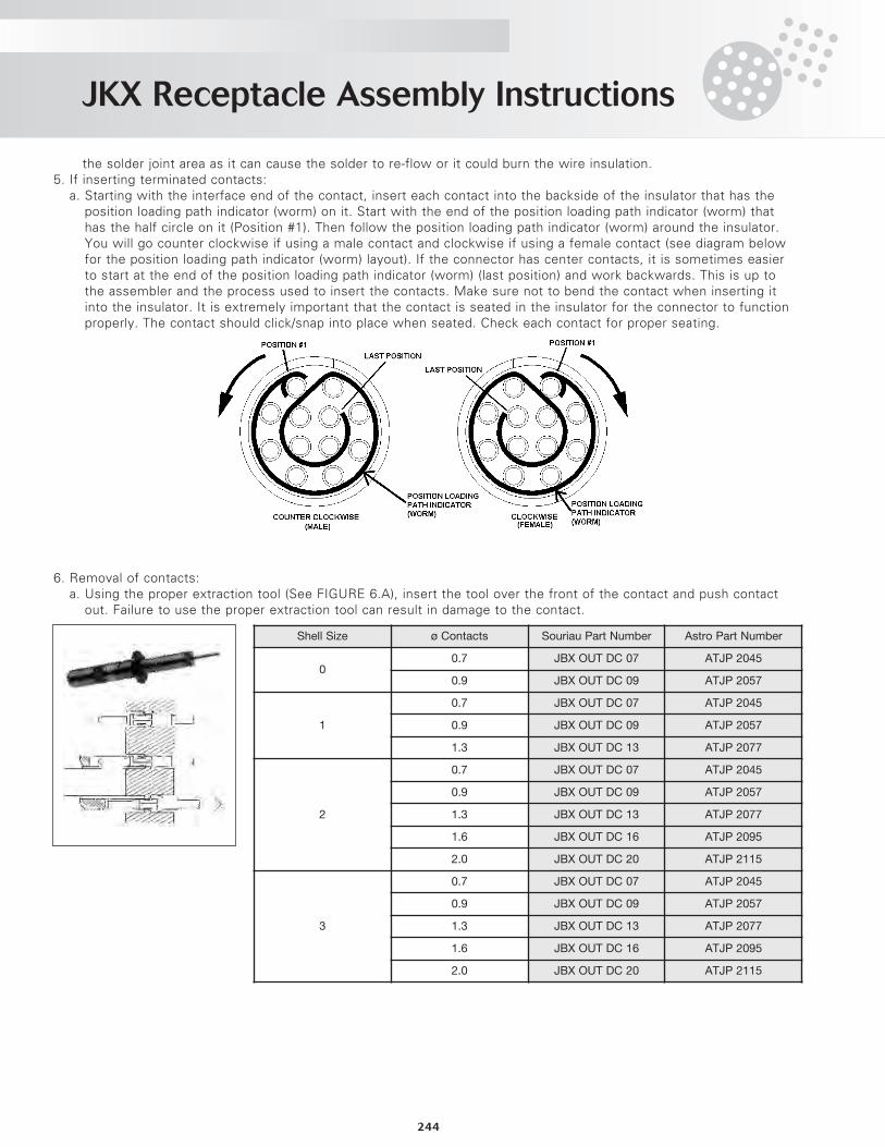
the solder joint area as it can cause the solder to re-flow or it could burn the wire insulation.5. If inserting terminated contacts:
a. Starting with the interface end of the contact, insert each contact into the backside of the insulator that has theposition loading path indicator (worm) on it. Start with the end of the position loading path indicator (worm) thathas the half circle on it (Position #1). Then follow the position loading path indicator (worm) around the insulator.You will go counter clockwise if using a male contact and clockwise if using a female contact (see diagram belowfor the position loading path indicator (worm) layout). If the connector has center contacts, it is sometimes easierto start at the end of the position loading path indicator (worm) (last position) and work backwards. This is up tothe assembler and the process used to insert the contacts. Make sure not to bend the contact when inserting itinto the insulator. It is extremely important that the contact is seated in the insulator for the connector to functionproperly. The contact should click/snap into place when seated. Check each contact for proper seating.
6. Removal of contacts:a. Using the proper extraction tool (See FIGURE 6.A), insert the tool over the front of the contact and push contact
out. Failure to use the proper extraction tool can result in damage to the contact.
Shell Size ø Contacts Souriau Part Number Astro Part Number
00.7 JBX OUT DC 07 ATJP 2045
0.9 JBX OUT DC 09 ATJP 2057
1
0.7 JBX OUT DC 07 ATJP 2045
0.9 JBX OUT DC 09 ATJP 2057
1.3 JBX OUT DC 13 ATJP 2077
2
0.7 JBX OUT DC 07 ATJP 2045
0.9 JBX OUT DC 09 ATJP 2057
1.3 JBX OUT DC 13 ATJP 2077
1.6 JBX OUT DC 16 ATJP 2095
2.0 JBX OUT DC 20 ATJP 2115
3
0.7 JBX OUT DC 07 ATJP 2045
0.9 JBX OUT DC 09 ATJP 2057
1.3 JBX OUT DC 13 ATJP 2077
1.6 JBX OUT DC 16 ATJP 2095
2.0 JBX OUT DC 20 ATJP 2115
JKX Receptacle Assembly Instructions
245
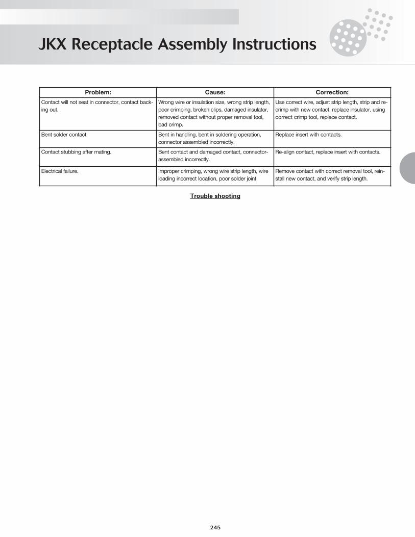
Trouble shooting
Problem: Cause: Correction:
Contact will not seat in connector, contact back-
ing out.
Wrong wire or insulation size, wrong strip length,
poor crimping, broken clips, damaged insulator,
removed contact without proper removal tool,
bad crimp.
Use correct wire, adjust strip length, strip and re-
crimp with new contact, replace insulator, using
correct crimp tool, replace contact.
Bent solder contact Bent in handling, bent in soldering operation,
connector assembled incorrectly.
Replace insert with contacts.
Contact stubbing after mating. Bent contact and damaged contact, connector-
assembled incorrectly.
Re-align contact, replace insert with contacts.
Electrical failure. Improper crimping, wrong wire strip length, wire
loading incorrect location, poor solder joint.
Remove contact with correct removal tool, rein-
stall new contact, and verify strip length.
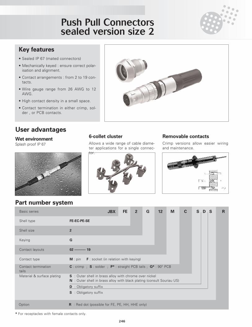
Push Pull Connectorssealed version size 2
246
Key features
• Sealed IP 67 (mated connectors)
• Mechanically keyed : ensure correct polar-isation and alignment.
• Contact arrangements : from 2 to 19 con-tacts.
• Wire gauge range from 26 AWG to 12AWG.
• High contact density in a small space.
• Contact termination in either crimp, sol-der , or PCB contacts.
Part number system
RS D SCM12G2FEJBXBasic series
Shell type FE-EC-PE-SE
Shell size 2
Keying G
Contact layouts 02 ---------- 19
Contact type M : pin F : socket (in relation with keying)
Contact termination C : crimp ; S : solder ; P* : straight PCB tails ; Q* : 90° PCBtailsMaterial & surface plating S : Outer shell in brass alloy with chrome over nickel
N : Outer shell in brass alloy with black plating (consult Souriau US)
D : Obligatory suffix
S : Obligatory suffix
Option R : Red dot (possible for FE, PE, HH, HHE only)
* For receptacles with female contacts only.
User advantages
Wet environmentSplash proof IP 67
6-collet cluster
Allows a wide range of cable diame-ter applications for a single connec-tor.
Removable contacts
Crimp versions allow easier wiringand maintenance.
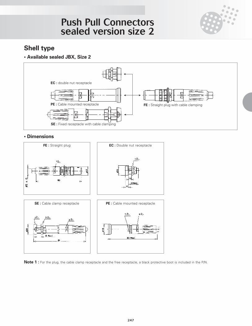
Push Pull Connectorssealed version size 2
247
Shell type
• Available sealed JBX, Size 2
• Dimensions
FE : Straight plug with cable clamping
EC : double nut receptacle
PE : Cable mounted receptacle
SE : Fixed receptacle with cable clamping
Note 1 : For the plug, the cable clamp receptacle and the free receptacle, a black protective boot is included in the P/N.
FE : Straight plug EC : Double nut receptacle
SE : Cable clamp receptacle PE : Cable mounted receptacle
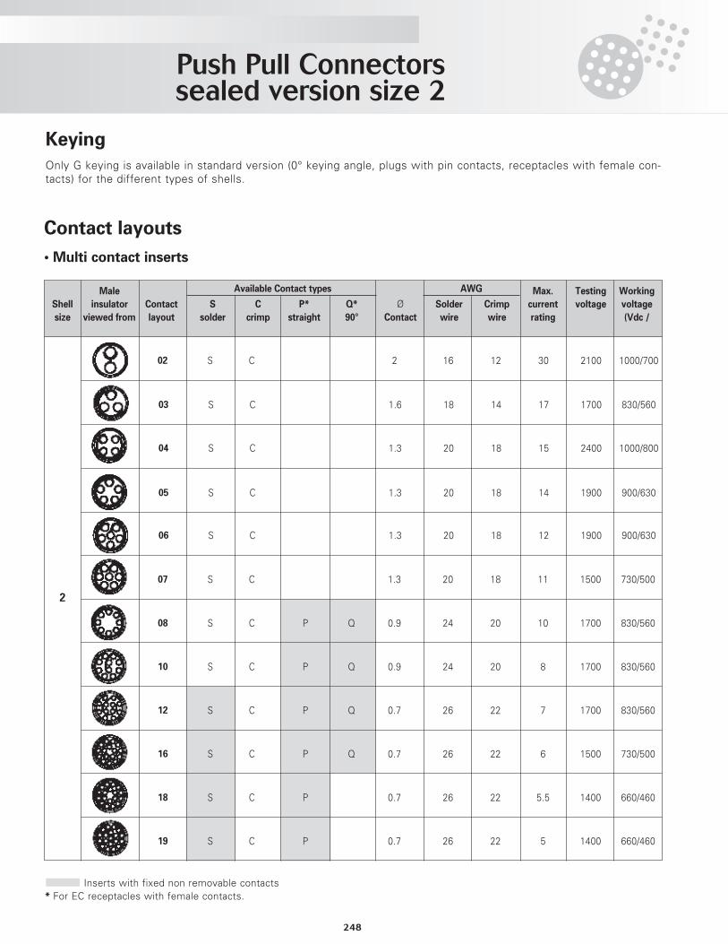
Push Pull Connectorssealed version size 2
248
KeyingOnly G keying is available in standard version (0° keying angle, plugs with pin contacts, receptacles with female con-tacts) for the different types of shells.
Contact layouts
• Multi contact inserts
Male AWG Max. Testing Working
Shell insulator Contact S C P* Q* Ø Solder Crimp current voltage voltage
size viewed from layout solder crimp straight 90° Contact wire wire rating (Vdc /
02 S C 2 16 12 30 2100 1000/700
03 S C 1.6 18 14 17 1700 830/560
04 S C 1.3 20 18 15 2400 1000/800
05 S C 1.3 20 18 14 1900 900/630
06 S C 1.3 20 18 12 1900 900/630
07 S C 1.3 20 18 11 1500 730/500
08 S C P Q 0.9 24 20 10 1700 830/560
10 S C P Q 0.9 24 20 8 1700 830/560
12 S C P Q 0.7 26 22 7 1700 830/560
16 S C P Q 0.7 26 22 6 1500 730/500
18 S C P 0.7 26 22 5.5 1400 660/460
19 S C P 0.7 26 22 5 1400 660/460
Inserts with fixed non removable contacts* For EC receptacles with female contacts.
Available Contact types
2
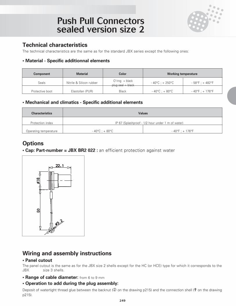
Push Pull Connectorssealed version size 2
249
Technical characteristicsThe technical characteristics are the same as for the standard JBX series except the following ones:
• Material - Specific additionnal elements
Component Material Color Working temperature
Seals Nitrile & Silicon rubberO’ring = black
- 40°C ; + 250°C - 58°F ; + 482°Fplug seal = black
Protective boot Elastollan (PUR) Black - 40°C ; + 80°C - 40°F ; + 176°F
Characteristics Values
Protection index IP 67 (Splashproof - 1/2 hour under 1 m of water)
Operating temperature - 40°C ; + 80°C - 40°F ; + 176°F
• Mechanical and climatics - Specific additional elements
Options• Cap: Part-number = JBX BR2 022 : an efficient protection against water
Wiring and assembly instructions• Panel cutoutThe panel cutout is the same as for the JBX size 2 shells except for the HC (or HCE) type for which it corresponds to theJBX size 3 shells.
• Range of cable diameter: from 6 to 9 mm
• Operation to add during the plug assembly:
Deposit of watertight thread glue between the backnut (¡ on the drawing p215) and the connection shell (? on the drawingp215).
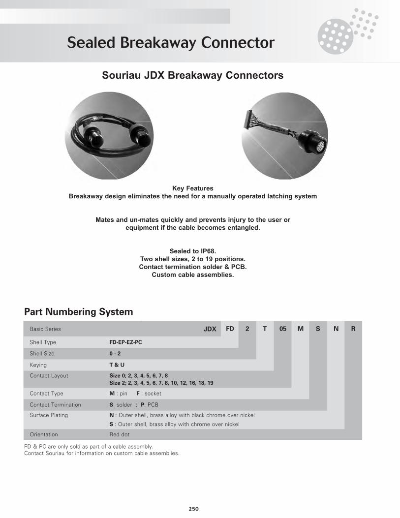
Sealed Breakaway Connector
250
Souriau JDX Breakaway Connectors
Key FeaturesBreakaway design eliminates the need for a manually operated latching system
Mates and un-mates quickly and prevents injury to the user or equipment if the cable becomes entangled.
Sealed to IP68.Two shell sizes, 2 to 19 positions.Contact termination solder & PCB.
Custom cable assemblies.
R NSM05T2FDJDXBasic Series
Shell Type FD-EP-EZ-PC
Shell Size 0 - 2
Keying T & U
Contact Layout Size 0; 2, 3, 4, 5, 6, 7, 8
Size 2; 2, 3, 4, 5, 6, 7, 8, 10, 12, 16, 18, 19
Contact Type M : pin F : socket
Contact Termination S: solder ; P: PCB
Surface Plating N : Outer shell, brass alloy with black chrome over nickel
S : Outer shell, brass alloy with chrome over nickel
Orientation Red dot
FD & PC are only sold as part of a cable assembly.Contact Souriau for information on custom cable assemblies.
Part Numbering System
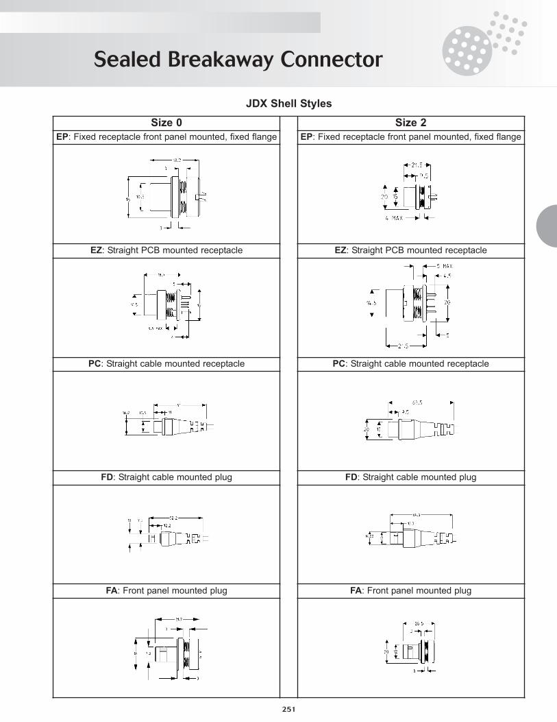
JDX Shell Styles
Sealed Breakaway Connector
251
Size 0 Size 2EP: Fixed receptacle front panel mounted, fixed flange EP: Fixed receptacle front panel mounted, fixed flange
EZ: Straight PCB mounted receptacle EZ: Straight PCB mounted receptacle
PC: Straight cable mounted receptacle PC: Straight cable mounted receptacle
FD: Straight cable mounted plug FD: Straight cable mounted plug
FA: Front panel mounted plug FA: Front panel mounted plug
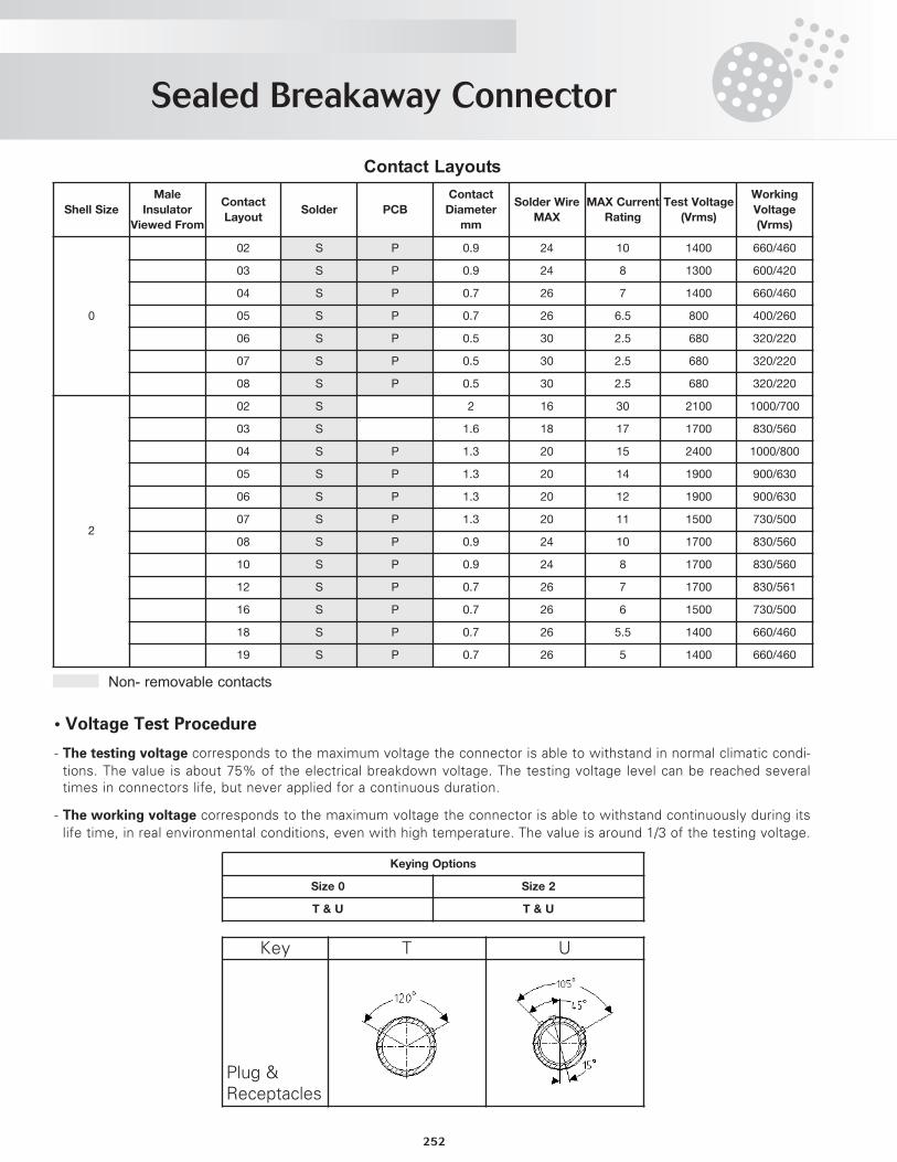
Sealed Breakaway Connector
252
Contact Layouts
Non- removable contacts
• Voltage Test Procedure
- The testing voltage corresponds to the maximum voltage the connector is able to withstand in normal climatic condi-tions. The value is about 75% of the electrical breakdown voltage. The testing voltage level can be reached severaltimes in connectors life, but never applied for a continuous duration.
- The working voltage corresponds to the maximum voltage the connector is able to withstand continuously during itslife time, in real environmental conditions, even with high temperature. The value is around 1/3 of the testing voltage.
Shell Size
Male
Insulator
Viewed From
Contact
LayoutSolder PCB
Contact
Diameter
mm
Solder Wire
MAX
MAX Current
Rating
Test Voltage
(Vrms)
Working
Voltage
(Vrms)
0
02 S P 0.9 24 10 1400 660/460
03 S P 0.9 24 8 1300 600/420
04 S P 0.7 26 7 1400 660/460
05 S P 0.7 26 6.5 800 400/260
06 S P 0.5 30 2.5 680 320/220
07 S P 0.5 30 2.5 680 320/220
08 S P 0.5 30 2.5 680 320/220
2
02 S 2 16 30 2100 1000/700
03 S 1.6 18 17 1700 830/560
04 S P 1.3 20 15 2400 1000/800
05 S P 1.3 20 14 1900 900/630
06 S P 1.3 20 12 1900 900/630
07 S P 1.3 20 11 1500 730/500
08 S P 0.9 24 10 1700 830/560
10 S P 0.9 24 8 1700 830/560
12 S P 0.7 26 7 1700 830/561
16 S P 0.7 26 6 1500 730/500
18 S P 0.7 26 5.5 1400 660/460
19 S P 0.7 26 5 1400 660/460
Keying Options
Size 0 Size 2
T & U T & U
Key T U
Plug &Receptacles
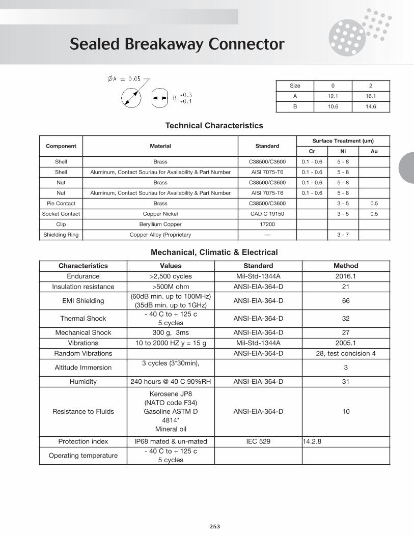
Technical Characteristics
Mechanical, Climatic & Electrical
Sealed Breakaway Connector
253
Size 0 2
A 12.1 16.1
B 10.6 14.6
Component Material StandardSurface Treatment (um)
Cr Ni Au
Shell Brass C38500/C3600 0.1 - 0.6 5 - 8
Shell Aluminum, Contact Souriau for Availability & Part Number AISI 7075-T6 0.1 - 0.6 5 - 8
Nut Brass C38500/C3600 0.1 - 0.6 5 - 8
Nut Aluminum, Contact Souriau for Availability & Part Number AISI 7075-T6 0.1 - 0.6 5 - 8
Pin Contact Brass C38500/C3600 3 - 5 0.5
Socket Contact Copper Nickel CAD C 19150 3 - 5 0.5
Clip Beryllium Copper 17200
Shielding Ring Copper Alloy (Proprietary — 3 - 7
Characteristics Values Standard Method
Endurance >2,500 cycles Mil-Std-1344A 2016.1
Insulation resistance >500M ohm ANSI-EIA-364-D 21
EMI Shielding(60dB min. up to 100MHz)
(35dB min. up to 1GHz)ANSI-EIA-364-D 66
Thermal Shock- 40 C to + 125 c
5 cyclesANSI-EIA-364-D 32
Mechanical Shock 300 g, 3ms ANSI-EIA-364-D 27
Vibrations 10 to 2000 HZ y = 15 g Mil-Std-1344A 2005.1
Random Vibrations ANSI-EIA-364-D 28, test concision 4
Altitude Immersion3 cycles (3*30min),
3
Humidity 240 hours @ 40 C 90%RH ANSI-EIA-364-D 31
Resistance to Fluids
Kerosene JP8
(NATO code F34)
Gasoline ASTM D
4814*
Mineral oil
ANSI-EIA-364-D 10
Protection index IP68 mated & un-mated IEC 529 14.2.8
Operating temperature- 40 C to + 125 c
5 cycles
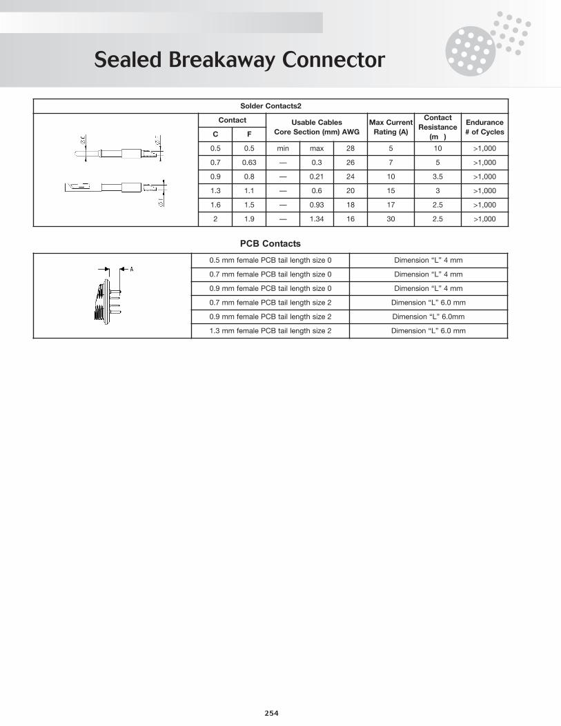
Sealed Breakaway Connector
254
PCB Contacts
Solder Contacts2
Contact Usable Cables
Core Section (mm) AWG
Max Current
Rating (A)
Contact
Resistance
(mΩ)
Endurance
# of CyclesC F
0.5 0.5 min max 28 5 10 >1,000
0.7 0.63 — 0.3 26 7 5 >1,000
0.9 0.8 — 0.21 24 10 3.5 >1,000
1.3 1.1 — 0.6 20 15 3 >1,000
1.6 1.5 — 0.93 18 17 2.5 >1,000
2 1.9 — 1.34 16 30 2.5 >1,000
0.5 mm female PCB tail length size 0 Dimension “L” 4 mm
0.7 mm female PCB tail length size 0 Dimension “L” 4 mm
0.9 mm female PCB tail length size 0 Dimension “L” 4 mm
0.7 mm female PCB tail length size 2 Dimension “L” 6.0 mm
0.9 mm female PCB tail length size 2 Dimension “L” 6.0mm
1.3 mm female PCB tail length size 2 Dimension “L” 6.0 mm
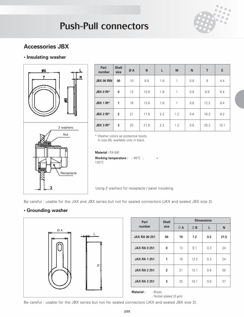
Push-Pull connectors
255
Accessories JBX
• Insulating washer
Part Shell
number size Ø A B L M N T E
JBX 00 RIN 00 10 8.8 1.8 1 0.8 8 4.4
JBX 0 RI* 0 12 10.8 1.8 1 0.8 9.9 6.4
JBX 1 RI* 1 16 13.8 1.8 1 0.8 12.2 8.4
JBX 2 RI* 2 21 17.8 2.2 1.2 0.8 16.2 8.2
JBX 3 RI* 3 25 21.8 2.2 1.2 0.8 20.2 10.1
* Washer colors as protective boots.In size 00, available only in black.
Material : PA 6/6
Working temperature : - 40°C ; +125°C
Using 2 washers for receptacle / panel insulating
2 washers
Nut
Receptacle
• Grounding washer
Material : - Brass- Nickel plated (3 µm)
Part Shell Dimensions
number size Ø A Ø B L N
JAX RA 00 251 00 10 7.2 0.3 21.5
JAX RA 0 251 0 13 9.1 0.3 24
JAX RA 1 251 1 16 12.2 0.3 24
JAX RA 2 251 2 21 15.1 0.8 35
JAX RA 3 251 3 25 18.1 0.8 37
Ø AL
N
Be careful : usable for the JAX and JBX series but not for sealed connectors (JKX and sealed JBX size 2).
Be careful : usable for the JBX series but not for sealed connectors (JKX and sealed JBX size 2).
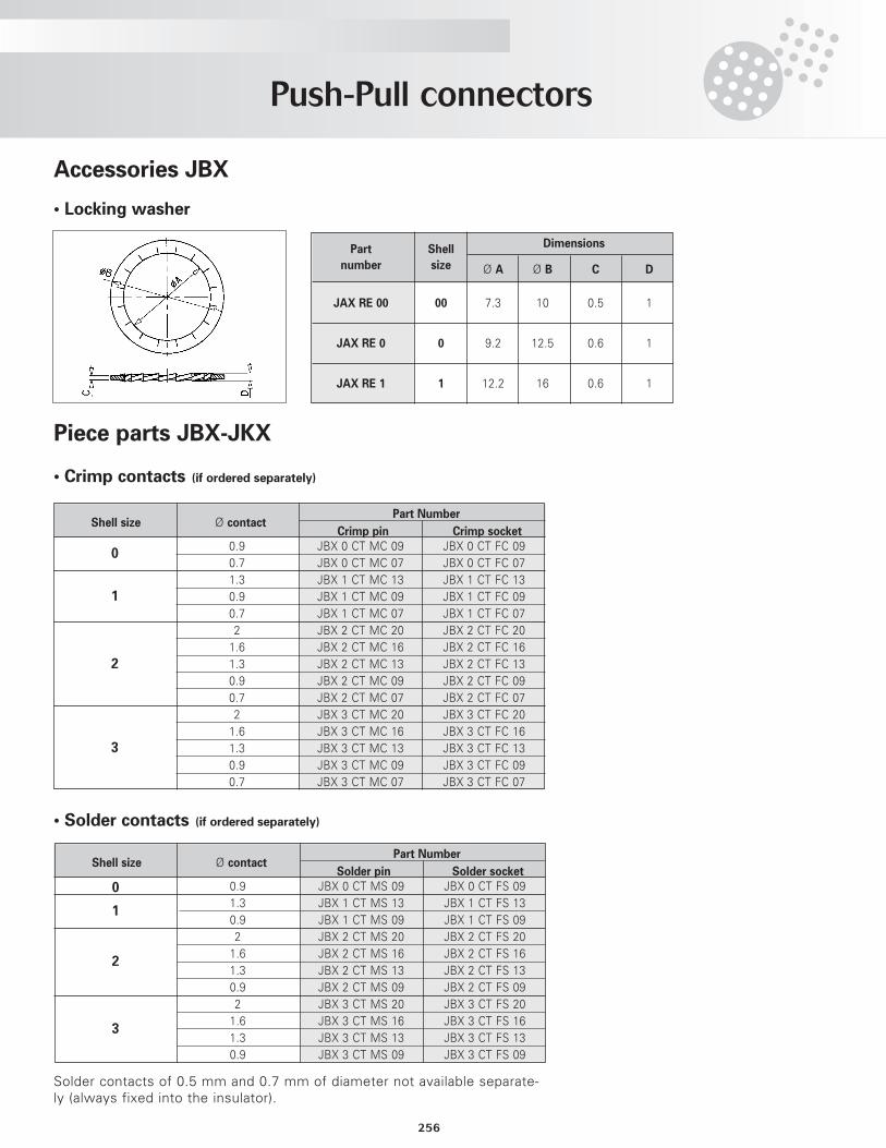
256
Push-Pull connectors
Piece parts JBX-JKX
• Crimp contacts (if ordered separately)
Accessories JBX
• Locking washer
Part NumberShell size Ø contact
Crimp pin Crimp socket
0
1
2
3
0.9 JBX 0 CT MC 09 JBX 0 CT FC 090.7 JBX 0 CT MC 07 JBX 0 CT FC 071.3 JBX 1 CT MC 13 JBX 1 CT FC 130.9 JBX 1 CT MC 09 JBX 1 CT FC 090.7 JBX 1 CT MC 07 JBX 1 CT FC 072 JBX 2 CT MC 20 JBX 2 CT FC 201.6 JBX 2 CT MC 16 JBX 2 CT FC 161.3 JBX 2 CT MC 13 JBX 2 CT FC 130.9 JBX 2 CT MC 09 JBX 2 CT FC 090.7 JBX 2 CT MC 07 JBX 2 CT FC 072 JBX 3 CT MC 20 JBX 3 CT FC 201.6 JBX 3 CT MC 16 JBX 3 CT FC 161.3 JBX 3 CT MC 13 JBX 3 CT FC 130.9 JBX 3 CT MC 09 JBX 3 CT FC 090.7 JBX 3 CT MC 07 JBX 3 CT FC 07
• Solder contacts (if ordered separately)
Part NumberShell size Ø contact
Solder pin Solder socket
0
1
2
3
0.9 JBX 0 CT MS 09 JBX 0 CT FS 091.3 JBX 1 CT MS 13 JBX 1 CT FS 130.9 JBX 1 CT MS 09 JBX 1 CT FS 092 JBX 2 CT MS 20 JBX 2 CT FS 201.6 JBX 2 CT MS 16 JBX 2 CT FS 161.3 JBX 2 CT MS 13 JBX 2 CT FS 130.9 JBX 2 CT MS 09 JBX 2 CT FS 092 JBX 3 CT MS 20 JBX 3 CT FS 201.6 JBX 3 CT MS 16 JBX 3 CT FS 161.3 JBX 3 CT MS 13 JBX 3 CT FS 130.9 JBX 3 CT MS 09 JBX 3 CT FS 09
Solder contacts of 0.5 mm and 0.7 mm of diameter not available separate-ly (always fixed into the insulator).
Part Shell Dimensions
number size Ø A Ø B C D
JAX RE 00 00 7.3 10 0.5 1
JAX RE 0 0 9.2 12.5 0.6 1
JAX RE 1 1 12.2 16 0.6 1
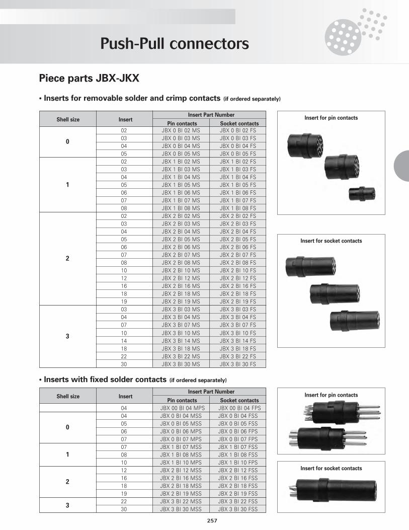
Push-Pull connectors
257
Piece parts JBX-JKX
• Inserts for removable solder and crimp contacts (if ordered separately)
• Inserts with fixed solder contacts (if ordered separately)
Insert Part NumberShell size Insert
Pin contacts Socket contacts
0
1
2
3
02 JBX 0 BI 02 MS JBX 0 BI 02 FS03 JBX 0 BI 03 MS JBX 0 BI 03 FS04 JBX 0 BI 04 MS JBX 0 BI 04 FS05 JBX 0 BI 05 MS JBX 0 BI 05 FS02 JBX 1 BI 02 MS JBX 1 BI 02 FS03 JBX 1 BI 03 MS JBX 1 BI 03 FS04 JBX 1 BI 04 MS JBX 1 BI 04 FS05 JBX 1 BI 05 MS JBX 1 BI 05 FS06 JBX 1 BI 06 MS JBX 1 BI 06 FS07 JBX 1 BI 07 MS JBX 1 BI 07 FS08 JBX 1 BI 08 MS JBX 1 BI 08 FS02 JBX 2 BI 02 MS JBX 2 BI 02 FS03 JBX 2 BI 03 MS JBX 2 BI 03 FS04 JBX 2 BI 04 MS JBX 2 BI 04 FS05 JBX 2 BI 05 MS JBX 2 BI 05 FS06 JBX 2 BI 06 MS JBX 2 BI 06 FS07 JBX 2 BI 07 MS JBX 2 BI 07 FS08 JBX 2 BI 08 MS JBX 2 BI 08 FS10 JBX 2 BI 10 MS JBX 2 BI 10 FS12 JBX 2 BI 12 MS JBX 2 BI 12 FS16 JBX 2 BI 16 MS JBX 2 BI 16 FS18 JBX 2 BI 18 MS JBX 2 BI 18 FS19 JBX 2 BI 19 MS JBX 2 BI 19 FS03 JBX 3 BI 03 MS JBX 3 BI 03 FS
Insert Part NumberShell size Insert
Pin contacts Socket contacts
0
1
2
3
04 JBX 00 BI 04 MPS JBX 00 BI 04 FPS04 JBX 0 BI 04 MSS JBX 0 BI 04 FSS05 JBX 0 BI 05 MSS JBX 0 BI 05 FSS06 JBX 0 BI 06 MPS JBX 0 BI 06 FPS07 JBX 0 BI 07 MPS JBX 0 BI 07 FPS07 JBX 1 BI 07 MSS JBX 1 BI 07 FSS08 JBX 1 BI 08 MSS JBX 1 BI 08 FSS10 JBX 1 BI 10 MPS JBX 1 BI 10 FPS12 JBX 2 BI 12 MSS JBX 2 BI 12 FSS16 JBX 2 BI 16 MSS JBX 2 BI 16 FSS18 JBX 2 BI 18 MSS JBX 2 BI 18 FSS19 JBX 2 BI 19 MSS JBX 2 BI 19 FSS22 JBX 3 BI 22 MSS JBX 3 BI 22 FSS30 JBX 3 BI 30 MSS JBX 3 BI 30 FSS
04 JBX 3 BI 04 MS JBX 3 BI 04 FS07 JBX 3 BI 07 MS JBX 3 BI 07 FS
10 JBX 3 BI 10 MS JBX 3 BI 10 FS14 JBX 3 BI 14 MS JBX 3 BI 14 FS18 JBX 3 BI 18 MS JBX 3 BI 18 FS22 JBX 3 BI 22 MS JBX 3 BI 22 FS30 JBX 3 BI 30 MS JBX 3 BI 30 FS
Insert for pin contacts
Insert for pin contacts
Insert for socket contacts
Insert for socket contacts
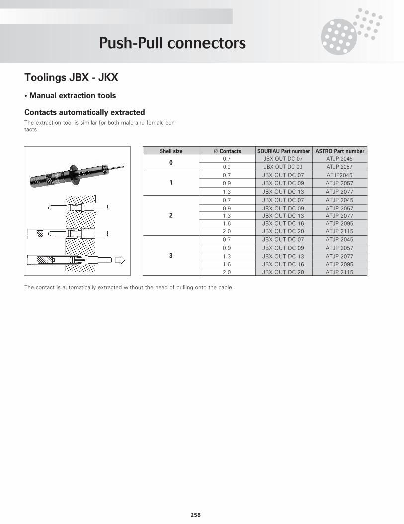
Push-Pull connectors
258
Toolings JBX - JKX
• Manual extraction tools
Contacts automatically extractedThe extraction tool is similar for both male and female con-tacts.
Shell size Ø Contacts SOURIAU Part number ASTRO Part number
0.7 JBX OUT DC 07 ATJP 20450.9 JBX OUT DC 09 ATJP 2057
0.7 JBX OUT DC 07 ATJP20450.9 JBX OUT DC 09 ATJP 2057
1.3 JBX OUT DC 13 ATJP 2077
0.7 JBX OUT DC 07 ATJP 2045
0.9 JBX OUT DC 09 ATJP 20571.3 JBX OUT DC 13 ATJP 20771.6 JBX OUT DC 16 ATJP 20952.0 JBX OUT DC 20 ATJP 2115
0.7 JBX OUT DC 07 ATJP 2045
0.9 JBX OUT DC 09 ATJP 2057
1.3 JBX OUT DC 13 ATJP 20771.6 JBX OUT DC 16 ATJP 20952.0 JBX OUT DC 20 ATJP 2115
0
1
2
3
The contact is automatically extracted without the need of pulling onto the cable.
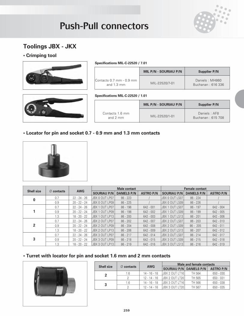
Push-Pull connectors
259
Toolings JBX - JKX
• Turret with locator for pin and socket 1.6 mm and 2 mm contacts
• Crimping tool
Male contact Female contact
SOURIAU P/N DANIELS P/N ASTRO P/N SOURIAU P/N DANIELS P/N ASTRO P/N
0.7 22 - 24 - 26 JBX 0 OUT LP07 86 - 223 / JBX 0 OUT LS07 86 - 224 /0.9 20 - 22 - 24 JBX 0 OUT LP09 86 - 225 / JBX 0 OUT LS09 86 - 226 /0.7 22 - 24 - 26 JBX 1 OUT LP07 86 - 196 642 - 001 JBX 1 OUT LS07 86 - 197 642 - 0040.9 20 - 22 - 24 JBX 1 OUT LP09 86 - 198 642 - 002 JBX 1 OUT LS09 86 - 199 642 - 0051.3 18 - 20 - 22 JBX 1 OUT LP13 86 - 200 642 - 003 JBX 1 OUT LS13 86 - 201 642 - 0060.7 22 - 24 - 26 JBX 2 OUT LP07 86 - 202 642 - 007 JBX 2 OUT LS07 86 - 203 642 - 0100.9 20 - 22 - 24 JBX 2 OUT LP09 86 - 204 642 - 008 JBX 2 OUT LS09 86 - 205 642 - 0111.3 18 - 20 - 22 JBX 2 OUT LP13 86 - 206 642 - 009 JBX 2 OUT LS13 86 - 207 642 - 0120.7 22 - 24 - 26 JBX 3 OUT LP07 86 - 217 642 - 014 JBX 3 OUT LS07 86 - 214 642 - 0170.9 20 - 22 - 24 JBX 3 OUT LP09 86 - 218 642 - 015 JBX 3 OUT LS09 86 - 215 642 - 0181.3 18 - 20 - 22 JBX 3 OUT LP13 86 - 219 642 - 016 JBX 3 OUT LS13 86 - 216 642 - 019
Shell size Ø contacts AWG
0
1
Male and female contacts
SOURIAU P/N DANIELS P/N ASTRO P/N
1.6 14 - 16 - 18 JBX 2 OUT LT16 TH 564 650 - 0302 12 - 14 - 16 JBX 2 OUT LT20 TH 565 650 - 0311.6 14 - 16 - 18 JBX 3 OUT LT16 TH 566 650 - 0382 12 - 14 - 16 JBX 3 OUT LT20 TH 567 650 - 035
Shell size Ø contacts AWG
2
3
2
3
Specifications MIL-C-22520 / 7.01
Specifications MIL-C-22520 / 1.01
MIL P/N - SOURIAU P/N Supplier P/N
Contacts 0.7 mm - 0.9 mmMIL-22520/7-01
Daniels : MH860and 1.3 mm Buchanan : 616 336
MIL P/N - SOURIAU P/N Supplier P/N
Contacts 1.6 mmMIL-22520/1-01
Daniels : AF8and 2 mm Buchanan : 615 708
• Locator for pin and socket 0.7 - 0.9 mm and 1.3 mm contacts
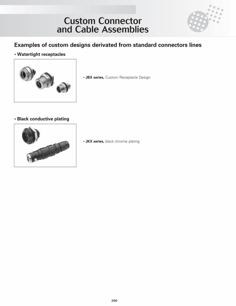
Custom Connector and Cable Assemblies
260
Examples of custom designs derivated from standard connectors lines
• Watertight receptacles
• Black conductive plating
• JBX series, Custom Receptacle Design
• JKX series, black chrome plating
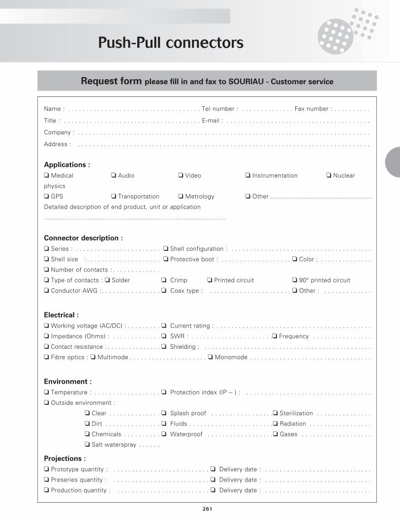
Push-Pull connectors
261
Request form please fill in and fax to SOURIAU - Customer service
Name : . . . . . . . . . . . . . . . . . . . . . . . . . . . . . . . . . . . . Tel number : . . . . . . . . . . . . . . Fax number : . . . . . . . . . .
Title : . . . . . . . . . . . . . . . . . . . . . . . . . . . . . . . . . . . . . E-mail : . . . . . . . . . . . . . . . . . . . . . . . . . . . . . . . . . . . . . . .
Company : . . . . . . . . . . . . . . . . . . . . . . . . . . . . . . . . . . . . . . . . . . . . . . . . . . . . . . . . . . . . . . . . . . . . . . . . . . . . . . .
Address : . . . . . . . . . . . . . . . . . . . . . . . . . . . . . . . . . . . . . . . . . . . . . . . . . . . . . . . . . . . . . . . . . . . . . . . . . . . . . . .
Applications :
o Medical o Audio o Video o Instrumentation o Nuclear
physics
o GPS o Transportation o Metrology o Other .......................................................
Detailed description of end product, unit or application
……………………………………………………………………………
Connector description :
o Series : . . . . . . . . . . . . . . . . . . . . . . . o Shell configuration : . . . . . . . . . . . . . . . . . . . . . . . . . . . . . . . . . . . . . .
o Shell size : . . . . . . . . . . . . . . . . . . . . o Protective boot : . . . . . . . . . . . . . . . . . . . o Color : . . . . . . . . . . . . . .
o Number of contacts : . . . . . . . . . . . . .
o Type of contacts : o Solder . . . . . . . . o Crimp . . . . . o Printed circuit . . . . . . . . . o 90° printed circuit
o Conductor AWG :. . . . . . . . . . . . . . . . o Coax type : . . . . . . . . . . . . . . . . . . . . . . o Other : . . . . . . . . . . . . .
Electrical :
o Working voltage (AC/DC) : . . . . . . . . . o Current rating : . . . . . . . . . . . . . . . . . . . . . . . . . . . . . . . . . . . . . . . . . .
o Impedance (Ohms) : . . . . . . . . . . . . . o SWR : . . . . . . . . . . . . . . . . . . . . . .o Frequency . . . . . . . . . . . . . . . .
o Contact resistance : . . . . . . . . . . . . . . . o Shielding : . . . . . . . . . . . . . . . . . . . . . . . . . . . . . . . . . . . . . . . . . . . . . . .
o Fibre optics : o Multimode . . . . . . . . . . . . . . . . . . . . . o Monomode . . . . . . . . . . . . . . . . . . . . . . . . . . . . . . . . .
Environment :
o Temperature : . . . . . . . . . . . . . . . . . . o Protection index (IP -- ) : . . . . . . . . . . . . . . . . . . . . . . . . . . . . . . . . . .
o Outside environment :
o Clear . . . . . . . . . . . . . . o Splash proof . . . . . . . . . . . . . . . . .o Sterilization . . . . . . . . . . . . . . .
o Dirt . . . . . . . . . . . . . . . o Fluids . . . . . . . . . . . . . . . . . . . . . . .o Radiation . . . . . . . . . . . . . . . . .
o Chemicals . . . . . . . . . . o Waterproof . . . . . . . . . . . . . . . . . .o Gases . . . . . . . . . . . . . . . . . . .
o Salt waterspray . . . . . .
Projections :
o Prototype quantity : . . . . . . . . . . . . . . . . . . . . . . . . . . o Delivery date : . . . . . . . . . . . . . . . . . . . . . . . . . . . . .
o Preseries quantity : . . . . . . . . . . . . . . . . . . . . . . . . . . o Delivery date : . . . . . . . . . . . . . . . . . . . . . . . . . . . . .
o Production quantity : . . . . . . . . . . . . . . . . . . . . . . . . . o Delivery date : . . . . . . . . . . . . . . . . . . . . . . . . . . . . .

Push-Pull connectors
262
• Millimeters / Inches • °C/°F
(mm) (inches)
0.1 0.003940.2 0.007880.3 0.011820.4 0.015760.5 0.019700.6 0.023640.7 0.027580.8 0.031520.9 0.035461.0 0.039401.1 0.043341.2 0.047281.3 0.051221.4 0.055161.5 0.059101.6 0.063041.7 0.066981.8 0.070921.9 0.074862.0 0.078802.1 0.082742.2 0.086682.3 0.090622.4 0.094562.5 0.098502.6 0.102442.7 0.106382.8 0.110322.9 0.114263.0 0.118203.1 0.122143.2 0.126083.3 0.130023.4 0.133963.5 0.137903.6 0.141843.7 0.145783.8 0.149723.9 0.153664.0 0.157604.1 0.161544.2 0.165484.3 0.169424.4 0.173364.5 0.177304.6 0.181244.7 0.185184.8 0.189124.9 0.193065.0 0.197005.2 0.204885.4 0.212765.6 0.220645.8 0.228526.0 0.236406.2 0.244286.4 0.252166.6 0.260046.8 0.267927.0 0.275807.2 0.283687.4 0.291567.6 0.299447.8 0.30732
(mm) (inches)
8.2 0.323088.4 0.330968.6 0.338848.8 0.346729.0 0.354609.2 0.362489.4 0.370369.6 0.378249.8 0.38612
10.0 0.3940010.5 0.4137011.0 0.4334011.5 0.4531012.0 0.4728012.5 0.4925013.0 0.5122013.5 0.5319014.0 0.5516014.5 0.5713015.0 0.5910015.5 0.6107016.0 0.6304016.5 0.6501017.0 0.6698017.5 0.6895018.0 0.7092018.5 0.7289019.0 0.7486019.5 0.7683020.0 0.7880020.5 0.8077021.0 0.8274021.5 0.8471022.0 0.8668022.5 0.8865023.0 0.9062023.5 0.9259024.0 0.9456024.5 0.9653025.0 0.9850025.5 1.0047026.0 1.0244026.5 1.0441027.0 1.0638027.5 1.0835028.0 1.1032028.5 1.1229029.0 1.1426029.5 1.1623030.0 1.1820030.5 1.2017031.0 1.2214031.5 1.2411032.0 1.2608032.5 1.2805033.0 1.3002033.5 1.3199034.0 1.3396034.5 1.3593035.0 1.3790035.5 1.3987036.0 1.4184036.5 1.4381037.0 1.45780
(mm) (inches)
38.0 1.4972038.5 1.5169039.0 1.5366039.5 1.5563040.0 1.5760040.5 1.5957041.0 1.6154041.5 1.6351042.0 1.6548042.5 1.6745043.0 1.6942043.5 1.7139044.0 1.7336044.5 1.7533045.0 1.7730045.5 1.7927046.0 1.8124046.5 1.8321047.0 1.8518047.5 1.8715048.0 1.8912048.5 1.9109049.0 1.9306049.5 1.9503050.0 1.9700051.0 2.0094052.0 2.0488053.0 2.0882054.0 2.1276055.0 2.1670056.0 2.2064057.0 2.2458058.0 2.2852059.0 2.3246060.0 2.3640061.0 2.4034062.0 2.4428063.0 2.4822064.0 2.5216065.0 2.5610066.0 2.6004067.0 2.6398068.0 2.6792069.0 2.7186070.0 2.7580071.0 2.7974072.0 2.8368073.0 2.8762074.0 2.9156075.0 2.9550080.0 3.1520085.0 3.3490090.0 3.54600
100.0 3.94000200.0 7.88000400.0 15.76000600.0 23.64000800.0 31.52000
1000.0 39.400001200.0 47.280001600.0 63.040002000.0 78.800003200.0 126.08000
(°C) (°F)
- 70 - 94- 65 - 85- 55 - 67- 50 - 58- 40 - 400 3237 98.680 176125 257150 302170 338200 392250 482
• Pressure conversion
bar psi mmhg (torr)10 145.0 76005 72.5 38002 29.0 15201 14.5 7600.5 7.2 380
mbar psi torr (mmhg)100 1.4 7650 0.72 3810 0.14 7.61.32 0.019 1