Embed Size (px)
Citation preview
South Asian Journal of Engineering and Technology Vol.2, No.16 (2016) 76–87
76
ISSN No: 2454-9614
PV BASED STAND ALONE AUTOMATIC WATER PUMPING
SYSTEM USING MPPT TECHNIQUE G.Manoj prabhu, R.Gowtham,B.Balajee,
Dept.Of EEE, AL-AMEEN ENGINEERING COLLGE, Erode -638 104, Tamil Nadu, India
*Corresponding Author:G.Manoj prabhu
E-mail:
Received: 22/11/2015, Revised: 28/12/2015 and Accepted: 10/03/2016
Abstract
The freely and abundantly available solar energy can be easily converted into electrical energy using Photo-Voltaic (PV) cells. PV
source has the advantage of low maintenance cost, pollution-free energy conversion process and low operating cost. In the
conventional method,. MPPT is employed to track maximum voltage from the solar panel. Hill climbing or Perturb and Observe
(P&O) MPPT algorithm which is used in the conventional method. The main drawback of P&O is at steady state condition the
operating point oscillates around the Maximum Power Point (MPP), which increase the wastage of some amount of available
energy and also the algorithm can be confused during those time intervals characterized by rapidly changing atmospheric
conditions. In the proposed method, PV cell is used as a source and the energy from solar panel can be trapped effectively by using
MPPT method which is aided with fuzzy logic controller. Mamdani membership function is used in fuzzy logic controller to get
crisp output. Depending on solar radiation and temperature, the MPPT with fuzzy controller gives optimized duty cycle. This work
is implemented in matlab using simulink. Simulation and experimental results have been presented to demonstrate the new features.
Keywords: Fuzzy Logic controller, Maximum Power Point Tracking, Photo Voltaic System
*Reviewed by ICETSET'16 organizing committee
1. Introduction
In recent years, to meet the future energy demands with pollution free and to give quality supply for the growing
environment conscious population. The present world attention is to go in for natural energy sources like solar, wind,
tidal and so on. From that solar energy is one of the major natural energy sources available on the earth.
Solar cells can be used to generate electricity from sunlight. It is a device that converts light energy into electrical
energy. Sometimes the term solar cell is reserved for devices intended specifically to capture energy from sunlight,
while the term photovoltaic cell is used when the light source is unspecified.
The most common kind of solar energy is photovoltaic cells, which directly convert light to electricity. They
South Asian Journal of Engineering and Technology Vol.2, No.16 (2016) 76–87
77
traditionally have been wafers of polysilicon, but modern thin film technologies have been under development. They are
less costly to produce, do not require silicon, and usually are less efficient in terms of yield of electricity produced from
photo energy input.
In order to extract maximum power from the panel, a maximum-power-point tracker (MPPT), which is a dc/dc
converter, is
usually connected between the panel and the load. Various maximum-power-point (MPP) tracking methods are
replaced by intelligent controllers, due to the fast response, flexibility in operation and reliability.
II.PHOTO-VOLTAIC SYSTEM
Photovoltaic is the best method for generating electric power by using solar cells to convert energy from the sun into
electricity. The photovoltaic effect refers to photons of light knocking electrons into a higher state of energy to create
electricity. The term photovoltaic denotes the unbiased operating mode of a photodiode in which current through the
device is entirely due to the transuded light energy. Virtually all photovoltaic devices are some type of photodiode.
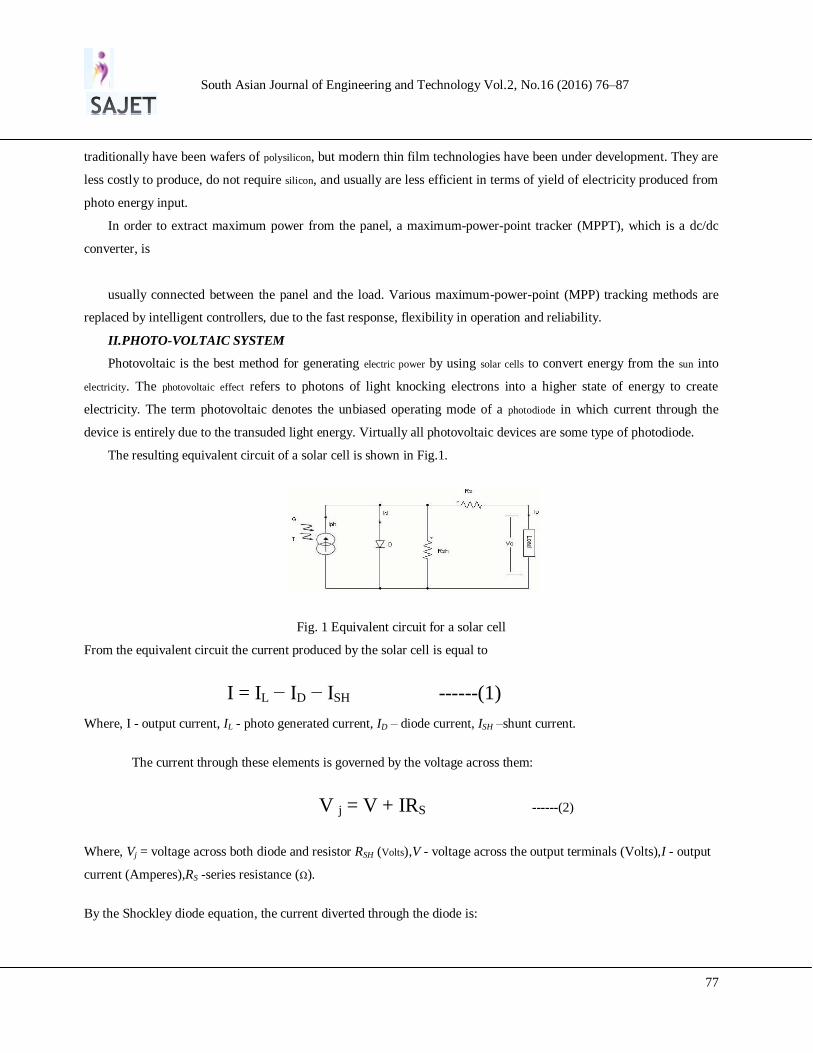
The resulting equivalent circuit of a solar cell is shown in Fig.1.
Fig. 1 Equivalent circuit for a solar cell
From the equivalent circuit the current produced by the solar cell is equal to
I = IL − ID − ISH ------(1)
Where, I - output current, IL - photo generated current, ID – diode current, ISH –shunt current.
The current through these elements is governed by the voltage across them:
V j = V + IRS ------(2)
Where, Vj = voltage across both diode and resistor RSH (Volts),V - voltage across the output terminals (Volts),I - output
current (Amperes),RS -series resistance (Ω).
By the Shockley diode equation, the current diverted through the diode is:
South Asian Journal of Engineering and Technology Vol.2, No.16 (2016) 76–87
78
ID= IO{exp [
]-1} -----(3)
Where, I0 - reverse saturation current (Amperes), n - diode ideality factor (1 for an ideal diode), q - elementary charge,
k - Boltzmann's constant, T - absolute temperature at 25°C.
By Ohm's law, the current diverted through the shunt resistor is:
ISH=
-----(4)
Where, RSH - shunt resistance (Ω).
Substituting these into the first equation produces the characteristic equation of a solar cell, which relates solar
cell parameters to the output current and voltage
I =IL-IO {exp [
]-1}-
----(5)
Open-circuit voltage and short-circuit current
When the cell is operated at open circuit, I = 0 and the voltage across the output terminals is defined as the open-
circuit voltage. Assuming the shunt resistance is high the open-circuit voltage VOC is:
VOC ≈
ln (
1) ------(6)
Similarly, when the cell is operated at short circuit, V = 0 and the current I through the terminals is defined as the
short-circuit current
ISC≈IL ------(7)
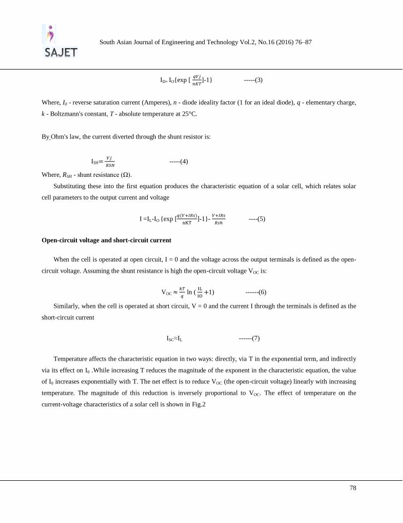
Temperature affects the characteristic equation in two ways: directly, via T in the exponential term, and indirectly
via its effect on I0 .While increasing T reduces the magnitude of the exponent in the characteristic equation, the value
of I0 increases exponentially with T. The net effect is to reduce VOC (the open-circuit voltage) linearly with increasing
temperature. The magnitude of this reduction is inversely proportional to VOC. The effect of temperature on the
current-voltage characteristics of a solar cell is shown in Fig.2
South Asian Journal of Engineering and Technology Vol.2, No.16 (2016) 76–87
79
Fig.2 Effect of temperature on the current- voltage
The conversion efficiency of a PV cell is the proportion of sunlight energy that the cell converts to electrical
energy. This is very important when discussing PV devices, because improving this efficiency is vital to making PV
energy competitive with more traditional sources of energy (e.g., fossil fuels).
III.BUCK-BOOST CONVERTER
Two different topologies are called buck–boost converter. Both of them can produce an output voltage much
larger (in absolute magnitude) than the input voltage. Both of them can produce a wide range of output voltage from
that maximum output voltage to almost zero. The inverting topology – The output voltage is of the opposite polarity as
the input
A buck (step-down) converter followed by a boost (step-up) converter – The output voltage is of the same polarity as the
input, and can be lower or higher than the input. Such a non-inverting buck-boost converter may use a single inductor
that is used as both the buck inductor and the boost inductor.
The buck–boost converter is a type of DC-to-DC converter that has an output voltage magnitude that is either
greater than or less than the input voltage magnitude. It is a switched-mode power supply with a similar circuit topology to
the boost converter and the buck converter.
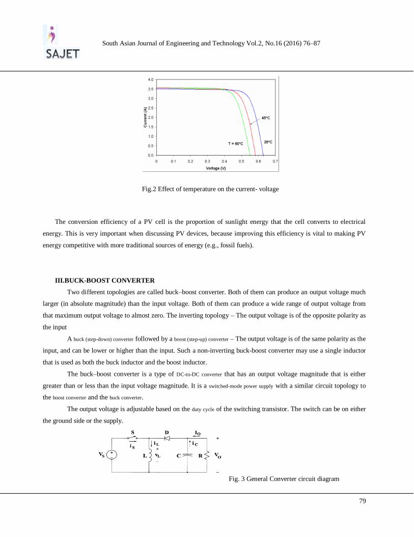
The output voltage is adjustable based on the duty cycle of the switching transistor. The switch can be on either
the ground side or the supply.
Fig. 3 General Converter circuit diagram
South Asian Journal of Engineering and Technology Vol.2, No.16 (2016) 76–87
80
The output voltage gain can be written as:
= -
----------(8)
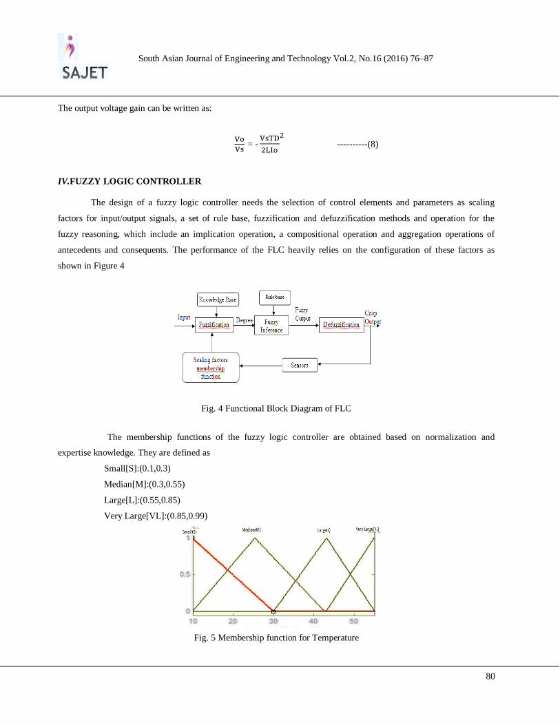
IV.FUZZY LOGIC CONTROLLER
The design of a fuzzy logic controller needs the selection of control elements and parameters as scaling
factors for input/output signals, a set of rule base, fuzzification and defuzzification methods and operation for the
fuzzy reasoning, which include an implication operation, a compositional operation and aggregation operations of
antecedents and consequents. The performance of the FLC heavily relies on the configuration of these factors as
shown in Figure 4
Fig. 4 Functional Block Diagram of FLC
The membership functions of the fuzzy logic controller are obtained based on normalization and
expertise knowledge. They are defined as
Small[S]:(0.1,0.3)
Median[M]:(0.3,0.55)
Large[L]:(0.55,0.85)
Very Large[VL]:(0.85,0.99)
Fig. 5 Membership function for Temperature
South Asian Journal of Engineering and Technology Vol.2, No.16 (2016) 76–87
81
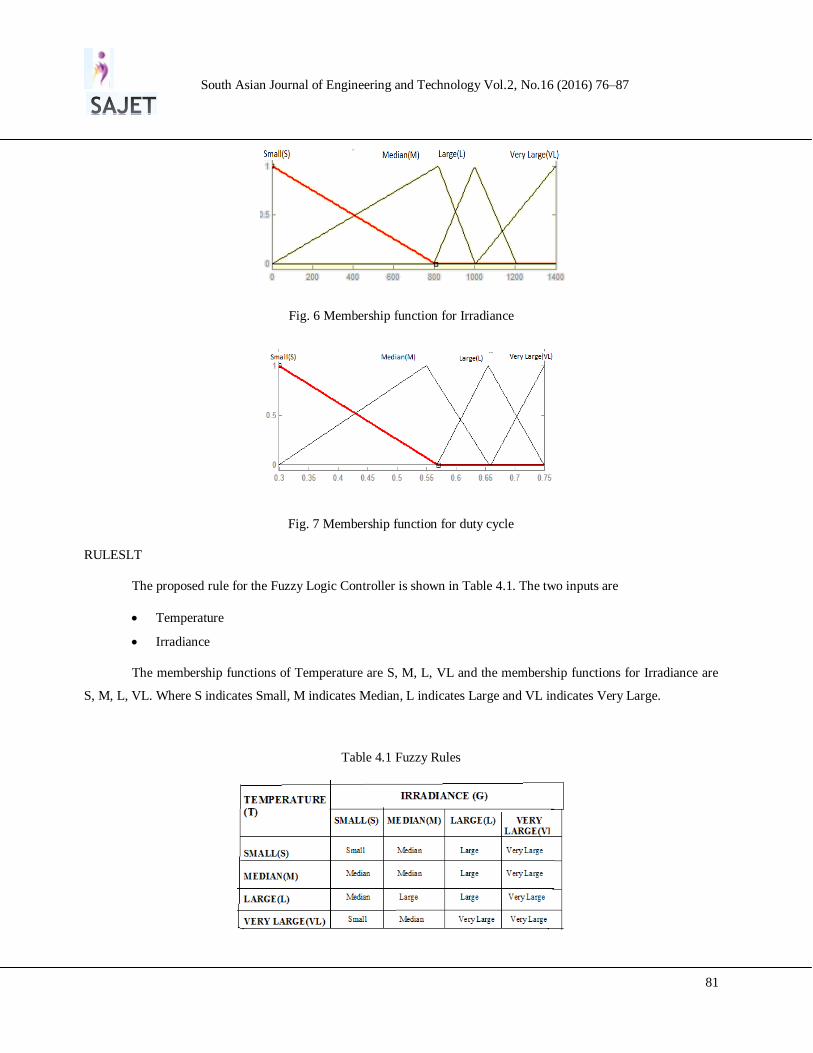
Fig. 6 Membership function for Irradiance
Fig. 7 Membership function for duty cycle
RULESLT
The proposed rule for the Fuzzy Logic Controller is shown in Table 4.1. The two inputs are
Temperature
Irradiance
The membership functions of Temperature are S, M, L, VL and the membership functions for Irradiance are
S, M, L, VL. Where S indicates Small, M indicates Median, L indicates Large and VL indicates Very Large.
Table 4.1 Fuzzy Rules
South Asian Journal of Engineering and Technology Vol.2, No.16 (2016) 76–87
82
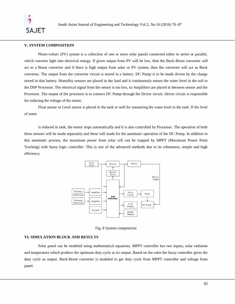
V. SYSTEM COMPOSITION
Photo-voltaic (PV) system is a collection of one or more solar panels connected either in series or parallel,
which converts light into electrical energy. If given output from PV will be low, then the Buck-Boost converter will
act as a Boost converter and if there is high output from solar or PV system, then the converter will act as Buck
converter. The output from the converter circuit is stored in a battery. DC Pump is to be made driven by the charge
stored in that battery. Humidity sensors are placed in the land and it continuously senses the water level in the soil to
the DSP Processor. The electrical signal from the sensor is too low, so Amplifiers are placed in between sensor and the
Processor. The output of the processor is to connect DC Pump through the Driver circuit. Driver circuit is responsible
for reducing the voltage of the motor.
Float sensor or Level sensor is placed in the tank or well for measuring the water level in the tank. If the level
of water
is reduced in tank, the motor stops automatically and it is also controlled by Processor. The operation of both
these sensors will be made separately and these will made for the automatic operation of the DC Pump. In addition to
this automatic process, the maximum power from solar cell can be trapped by MPPT (Maximum Power Point
Tracking) with fuzzy logic controller. This is one of the advanced methods due to its robustness, simple and high
efficiency.
Fig. 8 System composition
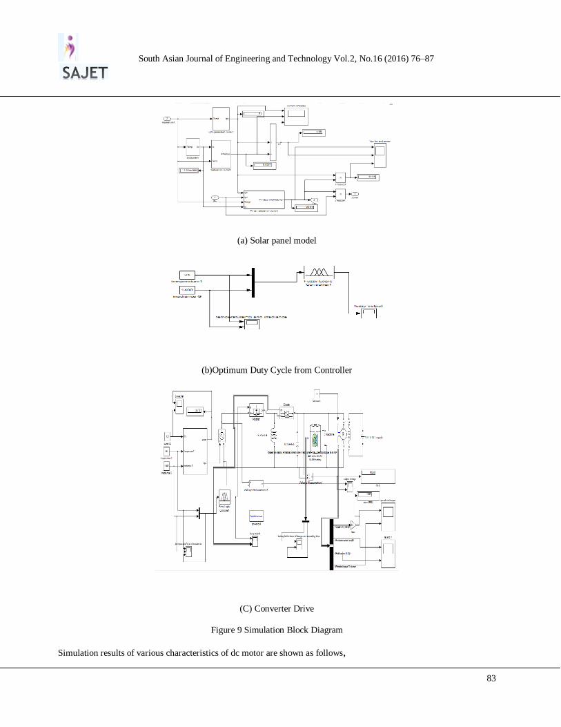
VI. SIMULATION BLOCK AND RESULTS
Solar panel can be modeled using mathematical equations. MPPT controller has two inputs, solar radiation
and temperature which produce the optimum duty cycle as its output. Based on the rules the fuzzy controller gives the
duty cycle as output. Buck-Boost converter is modeled to get duty cycle from MPPT controller and voltage from
panel.
South Asian Journal of Engineering and Technology Vol.2, No.16 (2016) 76–87
83
(a) Solar panel model
(b)Optimum Duty Cycle from Controller
(C) Converter Drive
Figure 9 Simulation Block Diagram
Simulation results of various characteristics of dc motor are shown as follows,
South Asian Journal of Engineering and Technology Vol.2, No.16 (2016) 76–87
84
(
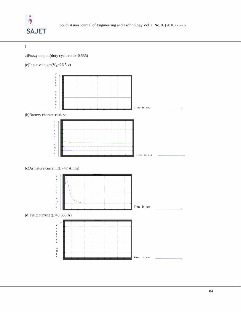
a)Fuzzy output:(duty cycle ratio=0.535)
(e)Input voltage:(Vin=26.5 v)
(b)Battery characteristics:
(c)Armature current:(Ia=47 Amps)
(d)Field current :(If=0.665 A)
South Asian Journal of Engineering and Technology Vol.2, No.16 (2016) 76–87
85
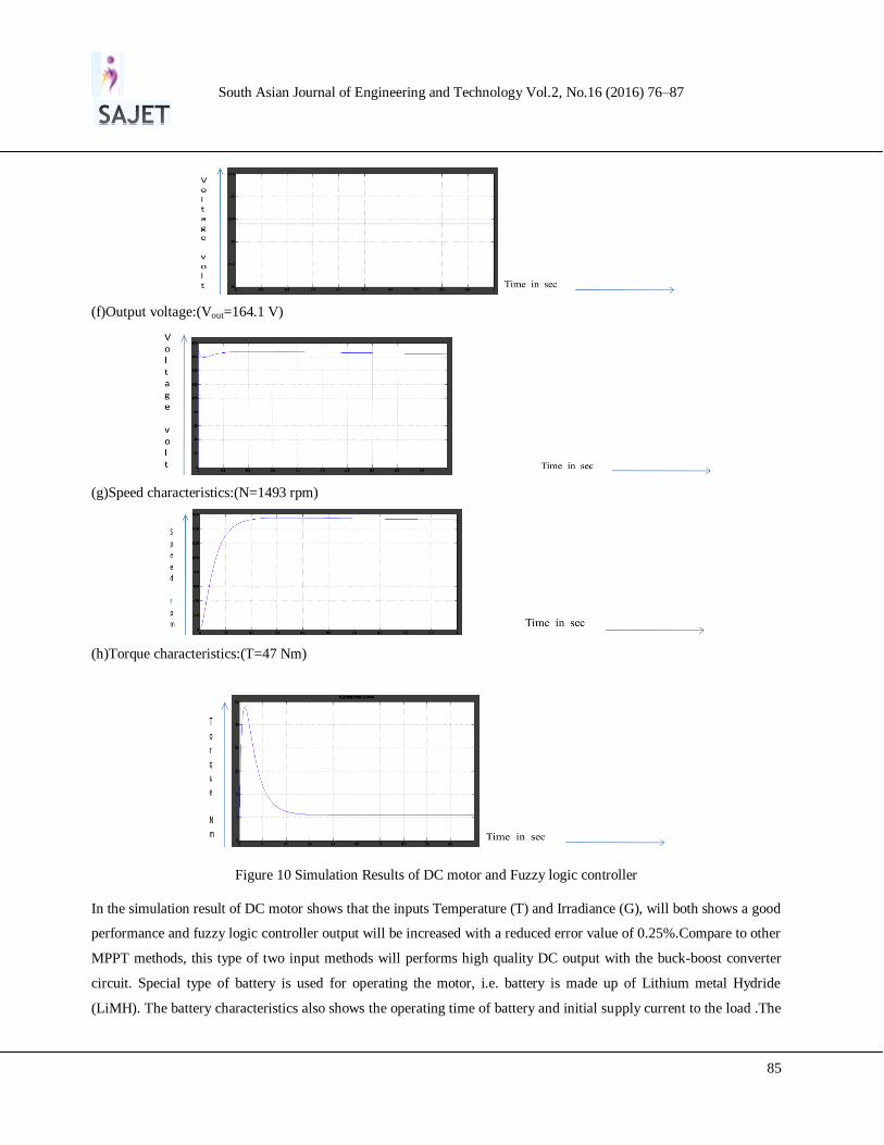
(f)Output voltage:(Vout=164.1 V)
(g)Speed characteristics:(N=1493 rpm)
(h)Torque characteristics:(T=47 Nm)
Figure 10 Simulation Results of DC motor and Fuzzy logic controller
In the simulation result of DC motor shows that the inputs Temperature (T) and Irradiance (G), will both shows a good
performance and fuzzy logic controller output will be increased with a reduced error value of 0.25%.Compare to other
MPPT methods, this type of two input methods will performs high quality DC output with the buck-boost converter
circuit. Special type of battery is used for operating the motor, i.e. battery is made up of Lithium metal Hydride
(LiMH). The battery characteristics also shows the operating time of battery and initial supply current to the load .The
South Asian Journal of Engineering and Technology Vol.2, No.16 (2016) 76–87
86
speed and torque characteristics obtained is smooth and regular. This shows that the motor connecting to the pump,
will operated in a Safe Operating Area (SOA) and runs in a desired voltage range.
VII.CONCLUSION
The main of the project is to achieve automatic operation of pumping system by using fuzzy logic controller
and also acquiring a steady state DC output voltage by buck-boost converter. Maximum power is trapped using a dc/dc
converter to which fuzzy logic control is applied. The insulation level and the intensity of sunlight falling on the earth
surface vary, thereby input voltage and current varies. As a result, the maximum power point is tracked and produces a
constant output voltage. This improves the energy conversion efficiency since more power is generated by
photovoltaic array.
This project also deals to sense the moisture level for the farm field without the external source. Here the
main thing is to control the motor depend upon the moisture and also reduces the wastage of electricity and improved
power factor.
REFERENCES
[1] Roger Gules, Juliano De Pellegrin Pacheco [July 2008]“A Maximum Power Point Tracking System With Parallel Connection for PV Stand-
Alone Applications” ieee transactions on industrial electronics, vol. 55, no. 7.
[2] M.S. Aït Cheikh, C. Larbes [2007] “Maximum Power point tracking using a fuzzy logic control scheme” Revue des Energies Renouvelables
Vol. 10 N°3.
[3] J. H. Lee, H. S. Bae [July 2008] “Resistive Control for a Photovoltaic Battery Charging System Using a Microcontroller” IEEE transactions
on industrial electronics, vol. 55.
[4] Wen Long Yu, Frank Shih [July 2010] “A DSP-Based Single-Stage Maximum Power Point Tracking PV Inverter” ieee transactions on
industrial electronics, vol. 55, no. 7.
[5] Fief Wang, Zhaohua Yang, Wu Mao [Feb. 2008] “Study of Photovoltaic Single-Phase Grid-Connected System” IEEE transactions on
industrial electronics, vol. 55, no. 7
[6] Yu Kang Lo [JULY 2005] “Optimization of Perturb and Observe Maximum Power Point Tracking Method” IEEE TRANSACTIONS ON
POWER ELECTRONICS, VOL.20,NO. 4.
[7] Nopporn [JULY 2007] “Maximum power point tracking using adaptive fuzzy logic control for grid-connected photovoltaic system” IEEE
TRANSACTIONS ON POWER ELECTRONICS, VOL. 23, NO. 5A.
[8] Yuen Haw Chang [MAR 2010] “A Maximum Power Point Tracking of PV System by Scaling Fuzzy Control” International multi conference
of engineers vol II, Hong Kong
[9] Jung Min kwon [2006]“Photovoltaic Power Conditioning System with Line Connection” IEEE TRANSACTIONS ON INDUSTRIAL
ELECTRONICS, VOL. 53, NO. 4
[10] A Betk and A. Moussi, “Performance optimization of photovoltaic induction motor pumping system”, Elsevier-Renewable Energy,
vol.29,pp. 2167-2181 , November 2004
[11] Abdel-Karim Daud and Marwan M. Mahmoud, “Solar powered induction motor-driven water pump operating on a desert well, simulation
and field tests”, Elsevier- Renewable Energy, vol. 30, pp.701714,April 2005.
[12] Roberto Faranda, Sonia Leva, “Energy comparison of MPPT techniques for PV Systems” WSEAS Transacations on Power Systems , vo l.
3, June 2008

South Asian Journal of Engineering and Technology Vol.2, No.16 (2016) 76–87
87
[13] C. Liu, B. Wu and R. Cheung ,“ Advanced algorithm for MPPT control of photovoltaic systems” Canadian Solar Buildings Conference ,
August 2004.