Embed Size (px)
Citation preview
2010-6 Prestige Vent Supl.
This document is intended to be used by a qualified heating contractor or servicetechnician. Read all instructions within this document and within the PRESTIGEBoiler Installation and Maintenance Manual, before proceeding with the installa-tion. It is recommended to follow the procedures in the steps given, skipping ormissing procedural steps could result in severe personal injury, death or sub-stantial property damage.
The installation must conform to the requirements of the authority having juris-diction or, in the absence of such requirements, to the National Fuel Gas Code,ANSI Z223.1/ NFPA 54, and/or Natural Gas and Propane Installation Code,CAN/CSA B149.1.
Revised Date: 9/25/15
L I S T E D
WARNING
NOTICE
PVC, CPVC, PP & SS Vent Supplement
Table of Contents
i
PRODUCT AND SAFETY INFORMATION
Definitions ................................................................................................................1Installer Information .................................................................................................1Homeowner Information...........................................................................................1
SECTION I - PRE-INSTALLATION REQUIREMENTS
1.1 Removal of an Existing Boiler from a Common Vent System .......................21.2 Vent/Combustion Air Piping and Materials.....................................................3
1.2.1 PVC and CPVC Vent and Combustion Air Piping and Fittings......31.2.2 PVC and CPVC Pipe Cement and Primer.....................................31.2.3 AL29-4C® Stainless Steel Vent Piping and Fittings ......................41.2.4 Polypropylene (PP) Vent Piping and Fittings.................................4
1.3 Vent/Combustion Air Equivalent Lengths.......................................................101.4 Vent Restrictions ............................................................................................10
1.4.1 2 Inch Vent Systems Restrictions for thePRESTIGE Solo 80, 110 & Excellence 110...........................10
1.4.2 3 Inch Vent Systems Restrictions ..................................................101.4.3 Rigid Polypropylene Vent System Restrictions..............................111.4.4 Flex Polypropylene Vent System Restrictions ...............................11
1.5 Combustion Air Contamination.......................................................................12
SECTION II - DIRECT VENT INSTALLATION OF VENT/AIR PIPING
2.1 Direct Vent - Vertical - Through the Roof or Unused Chimney......................132.1.1 Determine Termination Location ....................................................132.1.2 Direct Vent - Vent Installation - Through the Roof .........................142.1.3 Termination Fittings - Through the Roof ........................................152.1.4 Direct Vent - Multiple Boiler Installation - Through the Roof..........15
2.2 Direct Vent - Horizontal - Sidewall .................................................................172.2.1 Determine Termination Location ....................................................172.2.2 Direct Vent - Vent Installation - Sidewall........................................182.2.3 Termination Fittings - Sidewall .......................................................182.2.4 Direct Vent - Multiple Boiler Installation - Sidewall ........................20
2.3 Direct Vent - Vertical Vent and Sidewall Combustion Air ...............................222.3.1 Determine Termination Location ....................................................222.3.2 Direct Vent - Vent Installation - Through the Roof .........................232.3.3 Direct Vent - Combustion Air Installation - Sidewall .....................232.3.4 Termination Fittings - Vertical & Sidewall.......................................242.3.5 Direct Vent - Multiple Boiler Installation -
Vertical Vent and Sidewall Combustion Air............................24
SECTION III - CATEGORY IV (INDOOR AIR) INSTALLATION OF VENT/AIR PIPING
3.1 Category IV - Vertical - Through the Roof or Unused Chimney ....................253.1.1 Determine Termination Location ....................................................253.1.2 Category IV - Vent Installation - Through the Roof........................263.1.3 Termination Fittings - Sidewall .......................................................263.1.4 Category IV - Multiple Boiler Installation - Through the Roof ........27
3.2 Category IV - Horizontal - Sidewall ................................................................273.2.1 Determine Termination Location ....................................................273.2.2 Category IV - Vent Installation - Sidewall ......................................293.2.3 Termination Fittings - Sidewall .......................................................293.2.4 Category IV - Multiple Boiler Installation - Sidewall .......................29
Table of Contents
ii
SECTION IV - INSTALLATION REQUIREMENT
4.1 Vent/Combustion Air Transitions ....................................................................304.1.1 3” To 2” (60 mm) Vent/Combustion Air Transition..........................304.1.2 3” To 4” (100 mm) Vent/Combustion Air Transition........................31
4.2 Insert Piping to PRESTIGE Adapters.............................................................314.3 Vent and Combustion Air Piping Installation Guidelines ................................32
4.3.1 PVC/CPVC Vent System ...............................................................324.3.2 Polypropylene or Stainless Steel Vent Systems............................32
SECTION V - MANIFOLD COMBUSTION AIR
5.1 Manifold Combustion Air Option for Multiple Prestige Boilers .......................335.2 Equivalent Length of Combustion Air Manifold ..............................................335.3 Horizontal Termination....................................................................................345.4 Installation Guidelines ....................................................................................345.5 Transition Boiler Air Piping to Manifold Guidelines ........................................35
SECTION VI - COMMONWEALTH OF MASSACHUSETTS
6.1 Installations with the Direct Vent Termination ElevationAt or Below 4 feet of Grade ...................................................36
6.2 Installations with the Direct Vent Termination ElevationAbove 4 feet of Grade ...........................................................37

1
Product and Safety Information
INSTALLER
Read all instructions as outlined in this manual andin the boiler installation manual. Failure to complywith these instructions in the order presented couldresult in personal injury or death.
This document is a supplement to the PRESTIGE boil-er installation and maintenance manual. The purposeof this supplement is for the proper installation of thevent and combustion air piping to the boiler.
All PRESTIGE vent and combustion air piping mustbe installed, terminated and joints sealed as out-lined in this manual. Failure to comply with instal-lation procedures outlined in this manual can resultin severe personal injury, death or substantial prop-erty damage.
This vent supplement outlines Direct Vent andCategory IV (Indoor Air) installations using PVC,CPVC, PP and SS materials, for other ventingoptions (materials, terminations, etc.) contact ACV-Triangle Tube.
WARNING
WARNING
NOTICE
The following terms are used throughout this manual tobring attention to the presence of potential hazards or toimportant information concerning the product.
Indicates the presence of a hazardous situationwhich, if ignored, will result in death, serious injuryor substantial property damage.
Indicates a potentially hazardous situation which, ifignored, can result in death, serious injury or sub-stantial property damage.
Indicates a potentially hazardous situation which, ifignored, may result in minor injury or substantialproperty damage.
Indicates special instructions on installation, opera-tion or maintenance, which are important to the equip-ment but not related to personal injury hazards.
Indicates recommendations made by ACV-TriangleTube for the installers which will help to ensure opti-mum operation and longevity of the equipment.
DANGER
WARNING
NOTICE
CAUTION
BEST PRACTICE
DEFINITIONS
ACV-Triangle Tube reserves the right to modify the technical specifications and components of its prod-ucts without prior notice.
NOTICE
HOMEOWNER• This manual is intended for use by a qualified heat-
ing contractor or service technician.• Please reference the User Information manual for
additional information.
• Ensure this document and all pertaining documentsare kept near the boiler to be used by the qualifiedheating contractor or service technician for future ref-erence.
2
1.0 Pre-Installation Requirements
SECTION I - PRE-INSTALLATIONREQUIREMENTS
1.1 Removal of an Existing Boiler from aCommon Vent System
Do not install the PRESTIGE into a common ventwith any other gas or oil appliances. This will causeflue gas spillage or appliance malfunction, resultingin possible severe personal injury, death or sub-stantial property damage.
When an existing boiler is removed from a commonventing system, the common venting system is likely tobe too large for proper venting of the remaining appli-ances. At the time of removal of an existing boiler, thefollowing steps shall be followed with each applianceremaining connected to the common venting systemplaced in operation, while the other appliances remain-ing connected to the common venting system are not inoperation.
1. Seal any unused openings in the common ventingsystem.
2. Visually inspect the venting system for proper sizeand horizontal pitch and determine there is noblockage or restriction, leakage, corrosion and otherdeficiencies which could cause an unsafe condition.
3. Insofar as is practical close all building doors andwindows and all doors between the space in whichthe appliances remaining connected to the commonventing system are located and other spaces of thebuilding. Turn on clothes dryers and any appliancenot connected to the common venting system. Turnon any exhaust fans, such as range hoods andbathroom exhausts, so they will operate at maxi-mum speed. Do not operate a summer exhaust fan.Close fireplace dampers.
DANGER
4. Place in operation the appliance being inspected.Follow the lighting instructions. Adjust thermostat soappliance will operate continuously.
5. Test for spillage at the draft hood relief opening after5 minutes of main burner operation. Use the flameof a match or candle, or smoke from a cigarette,cigar or pipe.
6. After it has been determined that each applianceremaining connected to the common venting systemproperly vents when tested as outlined above,return doors, windows, exhaust fans, fireplacedampers and any other gas-burning appliance totheir previous condition of use.
7. Any improper operation of the common venting sys-tem should be corrected so the installation conformswith the National Fuel Gas Code, ANSIZ223.1/NFPA 54 and/or CAN/CSA B149.1 ,Installation Codes. When resizing any portion of thecommon venting system, the common venting sys-tem should be resized to approach the minimumsize as determined using the appropriate tables inPart 11 of the National Fuel Gas Code, ANSIZ223.1/NFPA 54 and/or CAN/CSA B149.1,Installation Codes.
3
1.0 Pre-Installation Requirements
1.2 Vent/Combustion Air Piping andMaterials
The installation must conform to the requirements ofthe authority having jurisdiction or, in the absence ofsuch requirements, to the National Fuel Gas Code,ANSI Z223.1/ NFPA 54, and/or Natural Gas andPropane Installation Code, CAN/CSA B149.1.
The Prestige is certified per ANSI Z21.13 as a CategoryIV (indoor air) or Direct Vent (sealed combustion) appli-ance. A Category IV appliance utilizes uncontaminatedindoor or outdoor air (surrounding the appliance) forcombustion. A Direct Vent appliance utilizes uncontami-nated outdoor air (piped directly to the appliance) forcombustion.
To reduce the potential risks associated with indoorcontaminates (listed on page 12), flammable vaporsand tight housing construction (little or no infiltra-tion air), it is recommended to pipe uncontaminatedcombustion air directly from the outdoors to theappliance. This practice also promotes higher sys-tem efficiency by reducing heated indoor air frombeing exhausted from the building and replaced bycold infiltration air.
The Prestige requires a Category IV venting system whichis designed for pressurized venting and condensate.
The vent and combustion air materials (piping, fit-tings and cement) must meet the listed require-ments in this manual. Failure to comply with thesematerial requirements could result in severe per-sonal injury, death or substantial property damage.
NOTICE
BEST PRACTICE
WARNING
1.2.1 PVC and CPVC Vent and Combustion AirPiping and Fittings
PVC Schedule 40 - ANSI/ASTM D1785PVC-DWV - ANSI/ASTM D2665CPVC Schedule 40 - ANSI/ASTM F441
1.2.2 PVC and CPVC Pipe Cement and PrimerPVC - ANSI/ASTM D2564CPVC - ANSI/ASTM F493
For installations in Canada, all piping, fittings andcement/primer material must be certified and listedto ULC-S636. Ipex Inc. is an approved manufacturerof ULC S636 vent components.
Use of cellular core PVC (ASTM F891) cellular coreCPVC, or Radel® (polyphenolsulfone) in ventingsystems is prohibited. Cellular core pipe may beused for combustion air piping.
DO NOT mix a PVC/CPVC vent system & componentswith other vent system materials & components. Sealall PVC and CPVC pipe and fittings with the appropri-ate primer and cement. Failure to comply with thisrequirement could cause the venting system to failresulting in leakage of flue products into the livingspace.
NOTICE
NOTICE
WARNING
4
1.0 Pre-Installation Requirements
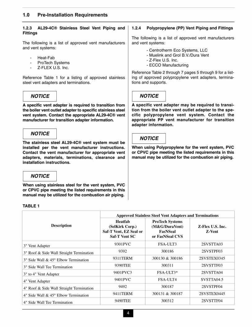
1.2.3 AL29-4C® Stainless Steel Vent Piping andFittings
The following is a list of approved vent manufacturersand vent systems:
- Heat-Fab - ProTech Systems - Z-FLEX U.S. Inc.
Reference Table 1 for a listing of approved stainlesssteel vent adapters and terminations.
A specific vent adapter is required to transition fromthe boiler vent outlet adapter to specific stainless steelvent system. Contact the appropriate AL29-4C® ventmanufacturer for transition adapter information.
The stainless steel AL29-4C® vent system must beinstalled per the vent manufacturer instructions.Contact the vent manufacturer for appropriate ventadapters, materials, terminations, clearance andinstallation instructions.
When using stainless steel for the vent system, PVCor CPVC pipe meeting the listed requirements in thismanual may be utilized for the combustion air piping.
NOTICE
NOTICE
NOTICE
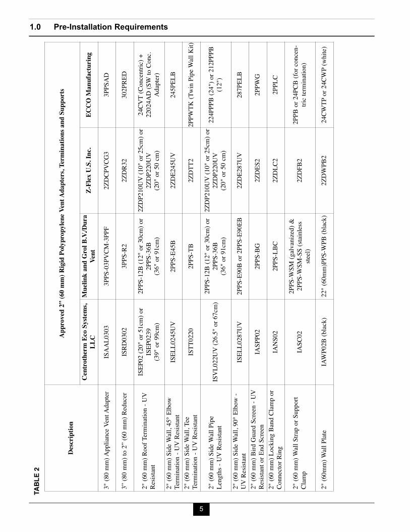
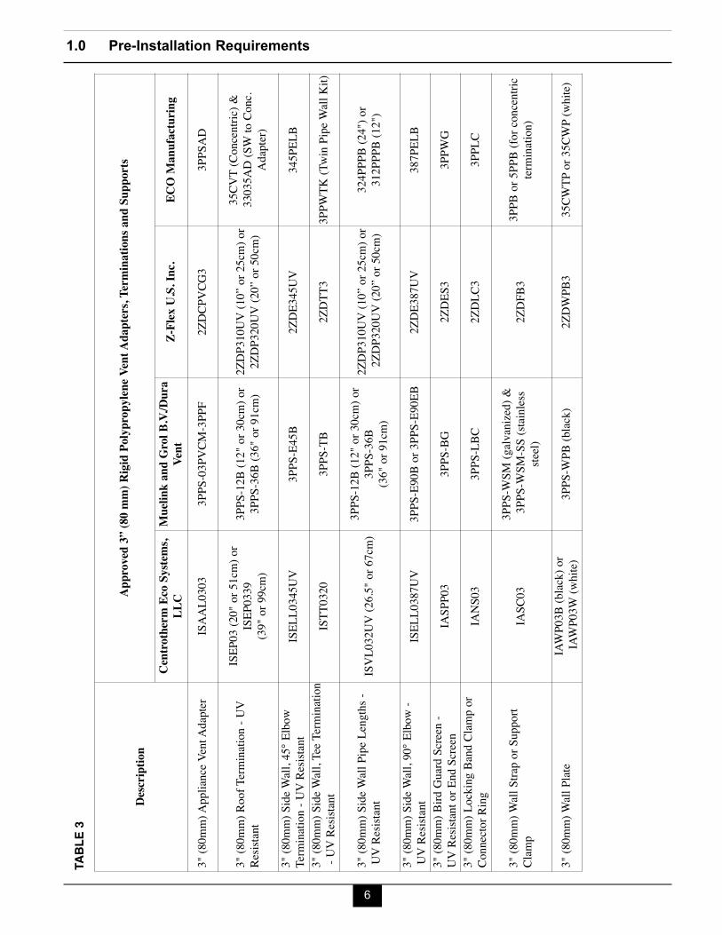
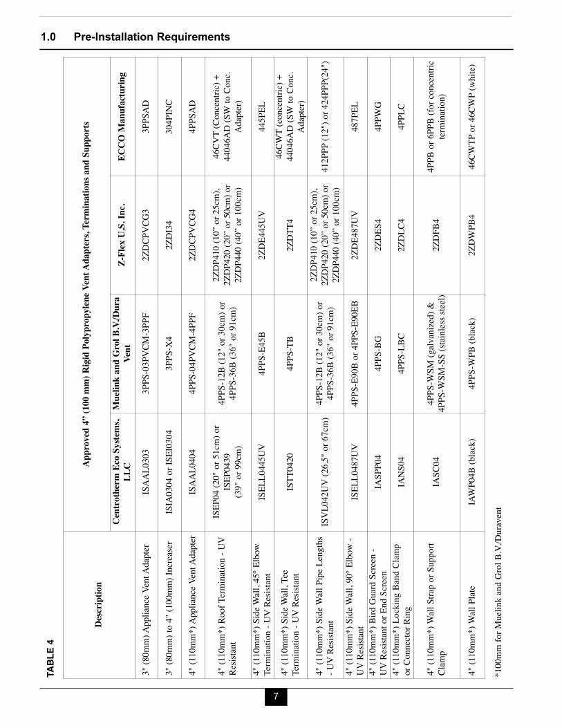
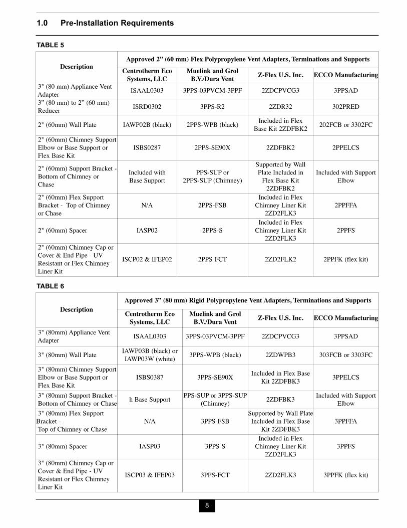
1.2.4 Polypropylene (PP) Vent Piping and Fittings
The following is a list of approved vent manufacturersand vent systems:
- Centrotherm Eco Systems, LLC- Muelink and Grol B.V./Dura Vent- Z-Flex U.S. Inc.- ECCO Manufacturing
Reference Table 2 through 7 pages 5 through 9 for a list-ing of approved polypropylene vent adapters, termina-tions and supports.
A specific vent adapter may be required to transi-tion from the boiler vent outlet adapter to the spe-cific polypropylene vent system. Contact theappropriate PP vent manufacturer for transitionadapter information.
When using Polypropylene for the vent system, PVCor CPVC pipe meeting the listed requirements in thismanual may be utilized for the combustion air piping.
NOTICE
NOTICE
TABLE 1
Description
Approved Stainless Steel Vent Adapters and TerminationsHeatfab
(SelKirk Corp.)Saf-T Vent, EZ Seal or
Saf-T Vent SC
ProTech Systems(M&G/DuraVent)
FasNSealor FasNSeal CVS
Z-Flex U.S. Inc.Z-Vent
3" Vent Adapter 9301PVC FSA-ULT3 2SVSTTA033" Roof & Side Wall Straight Termination 9392 300186 2SVSTPF033" Side Wall & 45° Elbow Termination 9311TERM 300130 & 300186 2SVSTEX03453" Side Wall Tee Termination 9390TEE 300311 2SVSTTF033" to 4" Vent Adapter 9401PVC3 FSA-ULT3* 2SVSTTA044" Vent Adapter 9401PVC FSA-ULT4 SVSTTA04.54" Roof & Side Wall Straight Termination 9492 300187 2SVSTPF044" Side Wall & 45° Elbow Termination 9411TERM 300131 & 300187 2SVSTEX04454" Side Wall Tee Termination 9490TEE 300312 2SVSTTF04
1.0 Pre-Installation Requirements
5
TABL
E 2
Descr
iption
Approved 2”
(60 m
m) Rigid P
olypropyle
ne Vent A
dapters, Term
inations an
d Supports
Centrotherm Eco S
ystem
s,LL
CMuelink a
nd Grol B
.V./Dura
Vent
Z-Flex U.S. In
c.EC
CO M
anufacturin
g
3" (8
0 mm)
App
lianc
e Ven
t Ada
pter
ISAA
L030
3 3P
PS-03
PVCM
-3PPF
2ZDC
PVCG
33P
PSAD
3” (8
0 mm)
to 2”
(60 m
m) R
educ
er IS
RD03
02
3PPS
-R2
2ZDR
3230
2PRE
D
2" (6
0 mm)
Roo
f Term
inatio
n - U
V Re
sistan
tIS
EP02
(20"
or 51
cm) o
rIS
EP02
39
(39" o
r 99c
m)
2PPS
-12B
(12" o
r 30c
m) or
2PPS
-36B
(36" o
r 91c
m)
2ZDP
210U
V (10
" or 2
5cm)
or2Z
DP22
0UV
(20" o
r 50 c
m)
24CV
T (C
once
ntric)
+ 22
024A
D (S
W to
Con
c.Ad
apter
)2"
(60 m
m) Si
de W
all, 4
5° E
lbow
Term
inatio
n - U
V Re
sistan
t IS
ELL0
245U
V 2P
PS-E
45B
2ZDE
245U
V24
5PEL
B2"
(60 m
m) Si
de W
all, T
ee
Term
inatio
n - U
V Re
sistan
t IS
TT02
20
2PPS
-TB
2ZDT
T22P
PWTK
(Twi
n Pipe
Wall
Kit)
2" (6
0 mm)
Side
Wall
Pipe
Le
ngths
- UV
Resi
stant
ISVL
022U
V (26
.5" or
67cm
) 2P
PS-12
B (12
" or 3
0cm)
or2P
PS-36
B (36
" or 9
1cm)
2ZDP
210U
V (10
" or 2
5cm)
or2Z
DP22
0UV
(20" o
r 50 c
m)22
4PPP
B (24
") or
212P
PPB
(12")
2" (6
0 mm)
Side
Wall
, 90°
Elbo
w -
UV R
esista
nt IS
ELL0
287U
V 2P
PS-E
90B
or 2P
PS-E
90EB
2ZDE
287U
V28
7PEL
B2"
(60 m
m) B
ird G
uard
Scree
n - U
V Re
sistan
t or E
nd Sc
reen
IASP
P02
2PPS
-BG
2ZDE
S22P
PWG
2" (6
0 mm)
Loc
king B
and C
lamp o
r Co
nnec
tor R
ing
IANS
02
2PPS
-LBC
2ZDL
C22P
PLC
2" (6
0 mm)
Wall
Strap
or Su
pport
Cl
amp
IASC
02
2PPS
-WSM
(galv
anize
d) &
2PPS
-WSM
-SS (
stainl
essste
el)2Z
DFB2
2PPB
or 24
PCB
(for c
once
n-tri
c term
inatio
n)
2" (6
0mm)
Wall
Plate
IA
WP0
2B (b
lack)
22" (
60mm
)PPS
-WPB
(blac
k)2Z
DWPB
224
CWTP
or 24
CWP (
white
)
1.0 Pre-Installation Requirements
6
TABL
E 3
Descr
iption
Approved 3”
(80 m
m) Rigid P
olypropyle
ne Vent A
dapters, Term
inations an
d Supports
Centrotherm Eco S
ystem
s,LL
CMuelink a
nd Grol B
.V./Dura
Vent
Z-Flex U.S. In
c.EC
O Manufacturin
g
3" (8
0mm)
App
lianc
e Ven
t Ada
pter
ISAA
L030
3 3P
PS-03
PVCM
-3PPF
2ZDC
PVCG
33P
PSAD
3" (8
0mm)
Roo
f Term
inatio
n - U
V Re
sistan
tIS
EP03
(20"
or 51
cm) o
rIS
EP03
39
(39" o
r 99c
m)3P
PS-12
B (12
" or 3
0cm)
or
3PPS
-36B
(36" o
r 91c
m)2Z
DP31
0UV
(10” o
r 25c
m) or
2Z
DP32
0UV
(20” o
r 50c
m)35
CVT
(Con
centr
ic) &
33
035A
D (S
W to
Con
c.Ad
apter
)3"
(80m
m) Si
de W
all, 4
5° E
lbow
Term
inatio
n - U
V Re
sistan
t IS
ELL0
345U
V 3P
PS-E
45B
2ZDE
345U
V34
5PEL
B3"
(80m
m) Si
de W
all, T
ee Te
rmina
tion
- UV
Resis
tant
ISTT
0320
3P
PS-T
B2Z
DTT3
3PPW
TK (T
win P
ipe W
all K
it)
3" (8
0mm)
Side
Wall
Pipe
Len
gths -
UV R
esista
nt IS
VL03
2UV
(26.5"
or 67
cm)
3PPS
-12B
(12" o
r 30c
m) or
3PPS
-36B
(36" o
r 91c
m)2Z
DP31
0UV
(10” o
r 25c
m) or
2ZDP
320U
V (20
” or 5
0cm)
324P
PPB
(24")
or 31
2PPP
B (12
")
3" (8
0mm)
Side
Wall
, 90°
Elbo
w -
UV R
esista
nt IS
ELL0
387U
V 3P
PS-E
90B
or 3P
PS-E
90EB
2ZDE
387U
V38
7PEL
B3"
(80m
m) B
ird G
uard
Scree
n -
UV R
esista
nt or
End S
creen
IASP
P03
3PPS
-BG
2ZDE
S33P
PWG
3" (8
0mm)
Loc
king B
and C
lamp o
r Co
nnec
tor R
ing
IANS
03
3PPS
-LBC
2ZDL
C33P
PLC
3" (8
0mm)
Wall
Strap
or Su
pport
Cl
amp
IASC
03
3PPS
-WSM
(galv
anize
d) &
3PPS
-WSM
-SS (
stainl
essste
el)2Z
DFB3
3PPB
or 5P
PB (f
or co
ncen
tric
termi
natio
n)
3" (8
0mm)
Wall
Plate
IA
WP0
3B (b
lack)
orIA
WP0
3W (w
hite)
3PPS
-WPB
(blac
k)2Z
DWPB
335
CWTP
or 35
CWP (
white
)
1.0 Pre-Installation Requirements
7
TABL
E 4
Descr
iption
Approved 4”
(100 mm)
Rigid P
olypropyle
ne Vent A
dapters, Term
inations an
d Supports
Centrotherm Eco S
ystem
s,LL
CMuelink a
nd Grol B
.V./Dura
Vent
Z-Flex U.S. In
c.EC
CO M
anufacturin
g
3" (8
0mm)
App
lianc
e Ven
t Ada
pter
ISAA
L030
3 3P
PS-03
PVCM
-3PPF
2ZDC
PVCG
33P
PSAD
3" (8
0mm)
to 4"
(100
mm) I
ncrea
serIS
IA03
04 or
ISEI
0304
3PPS
-X4
2ZDI
34
304P
INC
4" (1
10mm
*) Ap
plian
ce V
ent A
dapte
r IS
AAL0
404
4PPS
-04PV
CM-4P
PF2Z
DCPV
CG4
4PPS
AD
4" (1
10mm
*) Ro
of Te
rmina
tion -
UV
Resis
tant
ISEP
04 (2
0" or
51cm
) or
ISEP
0439
(39
" or 9
9cm)
4PPS
-12B
(12" o
r 30c
m) or
4P
PS-36
B (36
" or 9
1cm)
2ZDP
410 (
10” o
r 25c
m),
2ZDP
420 (
20” o
r 50c
m) or
2Z
DP44
0 (40
” or 1
00cm
)
46CV
T (C
once
ntric)
+44
046A
D (S
W to
Con
c.Ad
apter
)4"
(110
mm*)
Side W
all, 4
5° E
lbow
Term
inatio
n - U
V Re
sistan
tIS
ELL0
445U
V4P
PS-E
45B
2ZDE
445U
V44
5PEL
4" (1
10mm
*) Sid
e Wall
, Tee
Te
rmina
tion -
UV
Resis
tant
ISTT
0420
4PPS
-TB
2ZDT
T446
CWT
(conc
entri
c) +
4404
6AD
(SW
to C
onc.
Adap
ter)
4" (1
10mm
*) Sid
e Wall
Pipe
Len
gths
- UV
Resis
tant
ISVL
042U
V (26
.5" or
67cm
)4P
PS-12
B (12
" or 3
0cm)
or4P
PS-36
B (36
" or 9
1cm)
2ZDP
410 (
10” o
r 25c
m),
2ZDP
420 (
20” o
r 50c
m) or
2Z
DP44
0 (40
” or 1
00cm
)41
2PPP
(12"
) or 4
24PP
P(24
")
4" (1
10mm
*) Sid
e Wall
, 90°
Elbo
w -
UV R
esista
nt IS
ELL0
487U
V4P
PS-E
90B
or 4P
PS-E
90EB
2ZDE
487U
V48
7PEL
4" (1
10mm
*) Bi
rd Gu
ard Sc
reen -
UV R
esista
nt or
End S
creen
IASP
P04
4PPS
-BG
2ZDE
S44P
PWG
4" (1
10mm
*) Lo
cking
Ban
d Clam
por
Conn
ector
Ring
IA
NS04
4PPS
-LBC
2ZDL
C44P
PLC
4" (1
10mm
*) W
all St
rap or
Supp
ortCl
amp
IASC
044P
PS-W
SM (g
alvan
ized)
& 4P
PS-W
SM-S
S (sta
inless
stee
l)2Z
DFB4
4PPB
or 6P
PB (f
or co
ncen
tric
termi
natio
n)
4" (1
10mm
*) W
all Pl
ate
IAW
P04B
(blac
k)4P
PS-W
PB (b
lack)
2ZDW
PB4
46CW
TP or
46CW
P (wh
ite)
*100
mm fo
r Mue
link a
nd G
rol B
.V./D
urave
nt
8
1.0 Pre-Installation Requirements
DescriptionApproved 2” (60 mm) Flex Polypropylene Vent Adapters, Terminations and Supports
Centrotherm EcoSystems, LLC
Muelink and GrolB.V./Dura Vent Z-Flex U.S. Inc. ECCO Manufacturing
3" (80 mm) Appliance VentAdapter ISAAL0303 3PPS-03PVCM-3PPF 2ZDCPVCG3 3PPSAD3” (80 mm) to 2” (60 mm)Reducer ISRD0302 3PPS-R2 2ZDR32 302PRED
2" (60mm) Wall Plate IAWP02B (black) 2PPS-WPB (black) Included in Flex Base Kit 2ZDFBK2 202FCB or 3302FC
2" (60mm) Chimney SupportElbow or Base Support or Flex Base Kit
ISBS0287 2PPS-SE90X 2ZDFBK2 2PPELCS
2" (60mm) Support Bracket -Bottom of Chimney or Chase
Included with Base Support
PPS-SUP or 2PPS-SUP (Chimney)
Supported by Wall Plate Included in Flex Base Kit2ZDFBK2
Included with SupportElbow
2" (60mm) Flex Support Bracket - Top of Chimney or Chase
N/A 2PPS-FSBIncluded in Flex
Chimney Liner Kit 2ZD2FLK3
2PPFFA
2" (60mm) Spacer IASP02 2PPS-SIncluded in Flex
Chimney Liner Kit 2ZD2FLK3
2PPFS
2" (60mm) Chimney Cap orCover & End Pipe - UV Resistant or Flex Chimney Liner Kit
ISCP02 & IFEP02 2PPS-FCT 2ZD2FLK2 2PPFK (flex kit)
TABLE 5
TABLE 6
DescriptionApproved 3” (80 mm) Rigid Polypropylene Vent Adapters, Terminations and SupportsCentrotherm EcoSystems, LLC
Muelink and GrolB.V./Dura Vent Z-Flex U.S. Inc. ECCO Manufacturing
3" (80mm) Appliance Vent Adapter ISAAL0303 3PPS-03PVCM-3PPF 2ZDCPVCG3 3PPSAD
3" (80mm) Wall Plate IAWP03B (black) or IAWP03W (white) 3PPS-WPB (black) 2ZDWPB3 303FCB or 3303FC
3" (80mm) Chimney Support Elbow or Base Support or Flex Base Kit
ISBS0387 3PPS-SE90X Included in Flex Base Kit 2ZDFBK3 3PPELCS
3" (80mm) Support Bracket - Bottom of Chimney or Chase h Base Support PPS-SUP or 3PPS-SUP
(Chimney) 2ZDFBK3 Included with SupportElbow
3" (80mm) Flex SupportBracket - Top of Chimney or Chase
N/A 3PPS-FSBSupported by Wall PlateIncluded in Flex Base
Kit 2ZDFBK33PPFFA
3" (80mm) Spacer IASP03 3PPS-SIncluded in Flex
Chimney Liner Kit 2ZD2FLK3
3PPFS
3" (80mm) Chimney Cap or Cover & End Pipe - UV Resistant or Flex Chimney Liner Kit
ISCP03 & IFEP03 3PPS-FCT 2ZD2FLK3 3PPFK (flex kit)
1.0 Pre-Installation Requirements
9
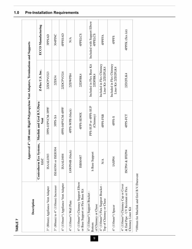
Descr
iption
Approved 4”
(100 mm)
Rigid P
olypropyle
ne Vent A
dapters, Term
inations an
d Supports
Centrotherm Eco S
ystem
s,LL
CMuelink a
nd Grol B
.V./Dura
Vent
Z-Flex U.S. In
c.EC
CO M
anufacturin
g
3" (8
0mm)
App
lianc
e Ven
t Ada
pter
ISAA
L030
3 3P
PS-03
PVCM
-3PPF
2ZDC
PVCG
33P
PSAD
3" (8
0mm)
to 4"
(110
mm) I
ncrea
serIS
IA03
04 or
ISEI
0304
3PPS
-X4
2ZDI
34
304P
INC
4" (1
10mm
*) Ap
plian
ce V
ent A
dapte
r IS
AAL0
404
4PPS
-04PV
CM-4P
PF2Z
DCPV
CG4
4PPS
SAD
4" (1
10mm
*) W
all Pl
ate
IAW
P04B
(blac
k)4P
PS-W
PB (b
lack)
2ZDW
PB4
N/A
4" (1
10mm
*) Ch
imne
y Sup
port
Elbo
w or
Base
Supp
ort or
Flex
Base
Kit
ISBS
0487
4P
PS-S
E90X
2ZDF
BK4
4PPE
LCS
4" (1
10mm
*) Su
pport
Brac
ket -
Botto
m of
Chim
ney o
r Cha
se h B
ase Su
pport
PP
S-SU
P or 4
PPS-
SUP
(Chim
ney)
Includ
ed in
Flex
Base
Kit
2ZDF
BK4
Includ
ed w
ith Su
pport
Elbo
w4P
PELC
S4"
(110
mm*)
Flex S
uppo
rt Br
acke
t -
Top o
f Chim
ney o
r Cha
se N/
A 4P
PS-F
SBInc
luded
in Fl
ex C
himne
yLi
ner K
it 2ZD
2FLK
44P
PFFA
4" (1
10mm
*) Sp
acer
IASP
04
4PPS
-SInc
luded
in Fl
ex C
himne
yLi
ner K
it 2ZD
2FLK
44P
PFS
4" (1
10mm
*) Ch
imne
y Cap
or C
over
& En
d Pipe
- UV
Resi
stant
or Fle
x Ch
imne
y Line
r Kit
ISCP
04 &
IFEP
04
4PPS
-FCT
2ZD2
FLK4
4PPF
K (fl
ex ki
t)
TABL
E 7
*100
mm fo
r Mue
link a
nd G
rol B
.V./D
urave
nt
1.0 Pre-Installation Requirements
10
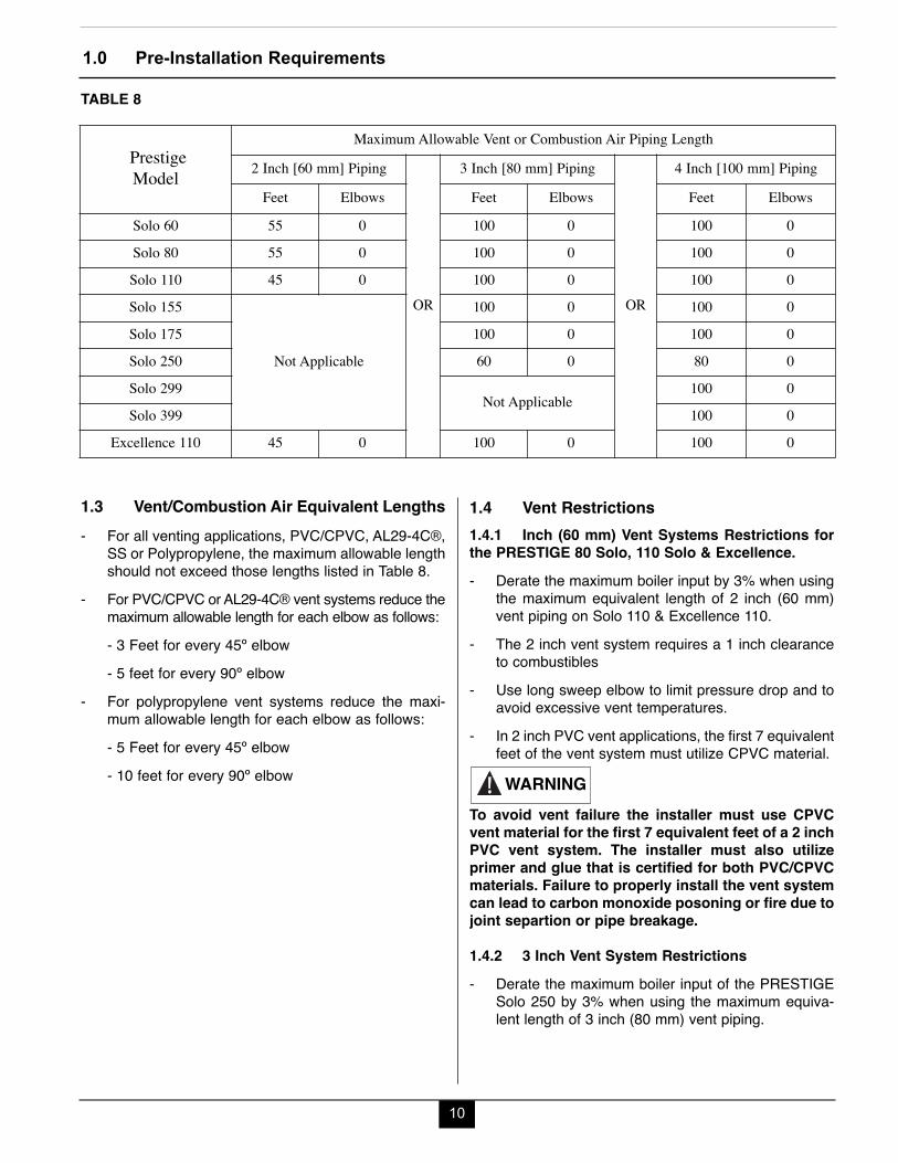
1.3 Vent/Combustion Air Equivalent Lengths- For all venting applications, PVC/CPVC, AL29-4C®,
SS or Polypropylene, the maximum allowable lengthshould not exceed those lengths listed in Table 8.
- For PVC/CPVC or AL29-4C® vent systems reduce themaximum allowable length for each elbow as follows:- 3 Feet for every 45º elbow- 5 feet for every 90º elbow
- For polypropylene vent systems reduce the maxi-mum allowable length for each elbow as follows:- 5 Feet for every 45º elbow- 10 feet for every 90º elbow
1.4 Vent Restrictions1.4.1 Inch (60 mm) Vent Systems Restrictions forthe PRESTIGE 80 Solo, 110 Solo & Excellence.- Derate the maximum boiler input by 3% when using
the maximum equivalent length of 2 inch (60 mm)vent piping on Solo 110 & Excellence 110.
- The 2 inch vent system requires a 1 inch clearanceto combustibles
- Use long sweep elbow to limit pressure drop and toavoid excessive vent temperatures.
- In 2 inch PVC vent applications, the first 7 equivalentfeet of the vent system must utilize CPVC material.
To avoid vent failure the installer must use CPVCvent material for the first 7 equivalent feet of a 2 inchPVC vent system. The installer must also utilizeprimer and glue that is certified for both PVC/CPVCmaterials. Failure to properly install the vent systemcan lead to carbon monoxide posoning or fire due tojoint separtion or pipe breakage.
1.4.2 3 Inch Vent System Restrictions - Derate the maximum boiler input of the PRESTIGE
Solo 250 by 3% when using the maximum equiva-lent length of 3 inch (80 mm) vent piping.
WARNING
TABLE 8
Prestige Model
Maximum Allowable Vent or Combustion Air Piping Length2 Inch [60 mm] Piping
OR
3 Inch [80 mm] Piping
OR
4 Inch [100 mm] PipingFeet Elbows Feet Elbows Feet Elbows
Solo 60 55 0 100 0 100 0Solo 80 55 0 100 0 100 0Solo 110 45 0 100 0 100 0Solo 155
Not Applicable
100 0 100 0Solo 175 100 0 100 0Solo 250 60 0 80 0Solo 299
Not Applicable100 0
Solo 399 100 0Excellence 110 45 0 100 0 100 0
1.0 Pre-Installation Requirements
11
1.4.4 Flex Polypropylene Vent SystemRestrictions- 3” Flex venting is limited up to the PRESTIGE Solo
175.- 2” Flex venting is limited up to the PRESTIGE Solo
110 & Excellence 110.
Contact approved polypropylene vent manufacturerfor a copy of their installation instructions. Read,understand and follow all of the vent manufacturer’sinstructions before beginning the installation.Contact vent manufacturer if you require any techni-cal support. Failure to properly install and supportvent system can lead to carbon monoxide poisoningor fire due to joint separation or pipe breakage.- Approved for vertical installations only, where a
clean, structurally sound unused chimney or chaseis used as a raceway.
- Vertical offsets must not exceed 45° and are limitedto a maximum number of 2.
- Requires rigid polypropylene vent pipe with lockingband clamps or connector rings and wall straps orsupport clamps from the appliance to the entrance ofthe chimney or chase.
- Maintain 5/8" per foot slope back toward appliance onall horizontal runs of rigid polypropylene vent pipe.
- The use of a wall plate is required to seal rigidpolypropylene vent pipe at the entrance of the chim-ney or chase to prevent mortar or cement from con-tacting the polypropylene vent pipe.
- Requires supports (elbow or base, flex chimney andbracket), spacers, chimney cap and end pipe.Consult vent manufacturer for complete list of otherparts required.
- Any termination piping external to the building mustbe UV resistant.
- Do not apply insulation directly to vent. Maintainvent manufacturers clearances to combustibles.
- Flex plastic venting systems shall not pass throughrated fire separations.
- Prior to assembly of any joints, ensure joint gasket ispresent and properly installed. Contact vent manufac-turer if gasket is missing or damaged. Verify theintegrity of joints upon completion of the vent system.
WARNING
1.4.3 Rigid Polypropylene Vent SystemRestrictions
Contact approved polypropylene vent manufacturerfor a copy of their installation instructions. Read,understand and follow all of the vent manufacturer’sinstructions before beginning the installation.Contact vent manufacturer if you require any techni-cal support. Failure to properly install and supportvent system can lead to carbon monoxide poisoningor fire due to joint separation or pipe breakage.- Rigid polypropylene vent pipe must be installed with
locking band clamps or connector rings and sup-ports (wall strap or clamp, elbow or base, etc.).Consult vent manufacturer for complete list of otherparts required.
- Maintain 5/8" per foot slope back toward applianceon all horizontal runs.
- The use of a wall plate is required to seal rigidpolypropylene vent pipe at the entrance of the chim-ney or chase to prevent mortar or cement from con-tacting the polypropylene vent pipe.
- Any termination piping external to the building mustbe UV resistant.
- Do not apply insulation directly to vent. Maintainvent manufacturers clearances to combustibles.
- Plastic venting systems shall not pass through ratedfire separations without approved fire stoppinginstalled in accordance with fire stopping manufac-turers instructions.
- Prior to assembly of any joints, ensure joint gasket ispresent and properly installed. Contact vent manufac-turer if gasket is missing or damaged. Verify theintegrity of joints upon completion of the vent system.
WARNING

1.0 Pre-Installation Requirements
12
1.5 Combustion Air Contamination
If the PRESTIGE combustion air inlet is located in anarea likely to cause or contain contamination, thecombustion air must be repiped and terminated atanother location. Contaminated combustion air willdamage the unit and its burner system, resulting inpossible severe personal injury, death or substantialproperty damage.
Do not operate the PRESTIGE if it’s combustion airinlet is located near a laundry room or pool facility.These areas will always contain hazardous con-taminants.
Pool and laundry products, common household andhobby products often contain fluorine or chlorinecompounds. When these chemicals pass throughthe burner and vent system, they can form strongacids. These acids will corrode the heat exchanger,burner components and vent system, causing seri-ous damage and presenting possible flue gasspillage or water leakage into the surrounding area.
Please read the information listed below. If contam-inating chemicals are located near the area of thecombustion air inlet, the installer should pipe thecombustion air inlet to an outside area free of thesechemicals.
DANGER
WARNING
Potential contaminating products- Spray cans containing chloro/fluorocarbons- Permanent Wave Solutions- Chlorinated wax - Chlorine - based swimming pool chemicals /
cleaners- Calcium Chloride used for thawing ice- Sodium Chloride used for water softening- Refrigerant leaks- Paint or varnish removers- Hydrochloric acid / muriatic acid- Cements and glues- Antistatic fabric softeners used in clothe dryers- Chlorine-type bleaches, detergents, and clean-
ing solvents found in household laundry rooms- Adhesives used to fasten building products and
other similar productsAreas likely to contain these products- Dry cleaning / laundry areas and establishments- Beauty salons- Metal fabrication shops- Swimming pools and health spas- Refrigeration Repair shops- Photo processing plants- Auto body shops- Plastic manufacturing plants- Furniture refinishing areas and establishments- New building construction- Remodeling areas- Garages with workshops
2.0 Direct Vent Installation of Vent/Air Piping
13
SECTION II - DIRECT VENT INSTALLATIONOF VENT/AIR PIPING
A Direct Vent appliance utilizes uncontaminated outdoorair (piped directly to the appliance) for combustion.
2.1 Direct Vent - Vertical - Through the Roofor Unused Chimney
The installation must conform to the requirements ofthe authority having jurisdiction or, in the absenceof such requirements, to the National Fuel GasCode, ANSI Z223.1/ NFPA 54, and/or Natural Gas andPropane Installation Code, CAN/CSA B149.1.
When using an inoperative chimney as a means of achase for the vent, the surrounding space within thechimney cannot be used to draw combustion air orvent another appliance.
A gas vent extending through a roof should not ter-minate near an adjacent wall or below any buildingextensions such as roof eaves, balconies or decks.Failure to comply with the required clearances inthis manual could result in severe personal injury,death or substantial property damage.
The information and diagrams outlining the fittingsand method of terminating the vent/combustion airare directly related to PVC/CPVC vent systems.When utilizing and AL29-4C® or Polypropylene ventsystem there may be some variations. Consult theappropriate vent manufacturer for recommenda-tions and clarifications.
2.1.1 Determine Termination Location
Locate the vent and combustion air termination using thefollowing guidelines:1. The total length of the vent or combustion air piping
must not exceed the limits given in Table 8 on page 10.
WARNING
NOTICE
NOTICE
NOTICE
Do not include the two 90º elbows used to terminatethe combustion air inlet exterior of the buildingwhen determining the total length of pipe.2. The combustion air piping must terminate in an
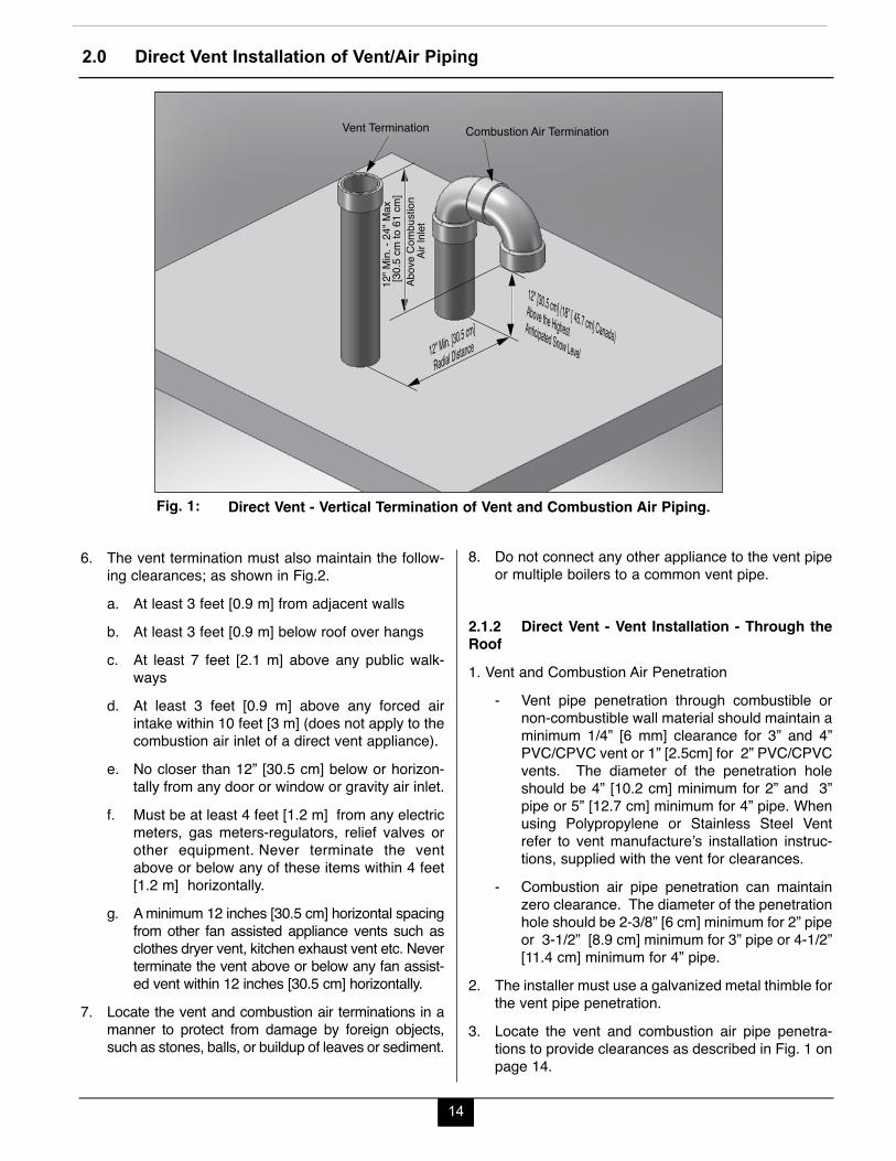
upside down “U” shape fashion using two 90ºelbows as shown in Fig. 1 page 14. The terminationmust be installed 12” [30.5 cm] (18” [45.7 cm]Canada) above the highest anticipated snow level.
3. The vent must terminate vertically with a coupling toaccept the bird screen and must be located 12” to 24”[30.5 cm to 61 cm] above the combustion air inlet asshown in Fig. 1 on page 14.
4. The vent and combustion air terminations must belocated a radial distance of 12” to 24” [30.5 cm to 61cm] from centerline of vent termination to centerlineof air termination as shown in Fig. 1 on page 14.
5. The following should be considered when deter-mining the location of the vent and combustion airterminations:a. Locate the vent termination where flue vapors
will not damage surrounding shrubs, plants orair conditioning equipment or be objectionableto the homeowner.
b. The flue products will form a noticeable plume ofwater vapor as they condense in colder air.Avoid terminating the vent in areas where theplume could obstruct window views.
c. Prevailing winds could cause freezing of fluegas condensation and a buildup of water / ice onsurrounding plants, building surfaces or com-bustion air inlet.
d. Avoid locations where prevailing winds couldaffect the performance of the boiler or causerecirculation of the flue gases, such as insidecorners of buildings, near adjacent buildings,vertical surfaces, window wells, stairwells,alcoves, courtyards, or other recessed areas.
e. Do not terminate the vent above doors or win-dows: flue condensate could freeze causing iceformations.
f. Locate the vent termination to prevent possiblecondensate damage to exterior finishes.
g. Avoid locations of possible accidental contact offlue vapors with people or pets.
NOTICE
2.0 Direct Vent Installation of Vent/Air Piping
14
12" Min. [30.5 cm]
Radial Distance
12" [30.5 cm] (18” [ 45.7 cm] Canada)Above the HighestAnticipated Snow Level
Vent Termination
[30.
5 cm
to 6
1 cm
]12
" Min.
- 24
" Max
Abov
e Co
mbu
stion
A
ir In
let
Combustion Air Termination
Direct Vent - Vertical Termination of Vent and Combustion Air Piping.Fig. 1:
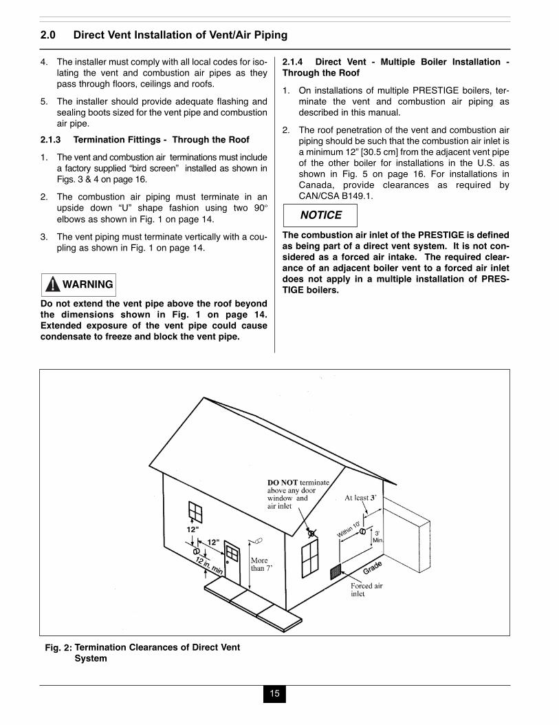
6. The vent termination must also maintain the follow-ing clearances; as shown in Fig.2.a. At least 3 feet [0.9 m] from adjacent wallsb. At least 3 feet [0.9 m] below roof over hangsc. At least 7 feet [2.1 m] above any public walk-
waysd. At least 3 feet [0.9 m] above any forced air
intake within 10 feet [3 m] (does not apply to thecombustion air inlet of a direct vent appliance).
e. No closer than 12” [30.5 cm] below or horizon-tally from any door or window or gravity air inlet.
f. Must be at least 4 feet [1.2 m] from any electricmeters, gas meters-regulators, relief valves orother equipment. Never terminate the ventabove or below any of these items within 4 feet[1.2 m] horizontally.
g. A minimum 12 inches [30.5 cm] horizontal spacingfrom other fan assisted appliance vents such asclothes dryer vent, kitchen exhaust vent etc. Neverterminate the vent above or below any fan assist-ed vent within 12 inches [30.5 cm] horizontally.
7. Locate the vent and combustion air terminations in amanner to protect from damage by foreign objects,such as stones, balls, or buildup of leaves or sediment.
8. Do not connect any other appliance to the vent pipeor multiple boilers to a common vent pipe.
2.1.2 Direct Vent - Vent Installation - Through theRoof1. Vent and Combustion Air Penetration
- Vent pipe penetration through combustible ornon-combustible wall material should maintain aminimum 1/4” [6 mm] clearance for 3” and 4”PVC/CPVC vent or 1” [2.5cm] for 2” PVC/CPVCvents. The diameter of the penetration holeshould be 4” [10.2 cm] minimum for 2” and 3”pipe or 5” [12.7 cm] minimum for 4” pipe. Whenusing Polypropylene or Stainless Steel Ventrefer to vent manufacture’s installation instruc-tions, supplied with the vent for clearances.
- Combustion air pipe penetration can maintainzero clearance. The diameter of the penetrationhole should be 2-3/8” [6 cm] minimum for 2” pipeor 3-1/2” [8.9 cm] minimum for 3” pipe or 4-1/2”[11.4 cm] minimum for 4” pipe.
2. The installer must use a galvanized metal thimble forthe vent pipe penetration.
3. Locate the vent and combustion air pipe penetra-tions to provide clearances as described in Fig. 1 onpage 14.
15
2.1.4 Direct Vent - Multiple Boiler Installation -Through the Roof1. On installations of multiple PRESTIGE boilers, ter-
minate the vent and combustion air piping asdescribed in this manual.
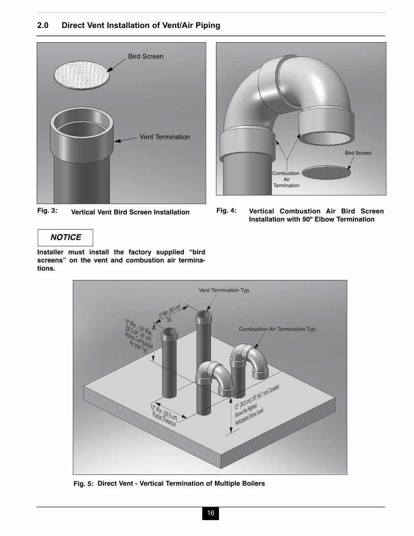
2. The roof penetration of the vent and combustion airpiping should be such that the combustion air inlet isa minimum 12” [30.5 cm] from the adjacent vent pipeof the other boiler for installations in the U.S. asshown in Fig. 5 on page 16. For installations inCanada, provide clearances as required byCAN/CSA B149.1.
The combustion air inlet of the PRESTIGE is definedas being part of a direct vent system. It is not con-sidered as a forced air intake. The required clear-ance of an adjacent boiler vent to a forced air inletdoes not apply in a multiple installation of PRES-TIGE boilers.
NOTICE
4. The installer must comply with all local codes for iso-lating the vent and combustion air pipes as theypass through floors, ceilings and roofs.
5. The installer should provide adequate flashing andsealing boots sized for the vent pipe and combustionair pipe.
2.1.3 Termination Fittings - Through the Roof1. The vent and combustion air terminations must include
a factory supplied “bird screen” installed as shown inFigs. 3 & 4 on page 16.
2. The combustion air piping must terminate in anupside down “U” shape fashion using two 90ºelbows as shown in Fig. 1 on page 14.
3. The vent piping must terminate vertically with a cou-pling as shown in Fig. 1 on page 14.
Do not extend the vent pipe above the roof beyondthe dimensions shown in Fig. 1 on page 14.Extended exposure of the vent pipe could causecondensate to freeze and block the vent pipe.
WARNING
2.0 Direct Vent Installation of Vent/Air Piping
Termination Clearances of Direct VentSystem
Fig. 2:
16
2.0 Direct Vent Installation of Vent/Air Piping
Vent Termination
Bird Screen
Vertical Vent Bird Screen InstallationFig. 3:
Installer must install the factory supplied “birdscreens” on the vent and combustion air termina-tions.
NOTICE
Combustion Air
Termination
Bird Screen
Vertical Combustion Air Bird ScreenInstallation with 90º Elbow Termination
Fig. 4:
Vent Termination Typ.
Combustion Air Termination Typ.
12" [30.5 cm] (18” [45.7 cm] Canada)
Above the Highest
Anticipated Snow Level
12" Min. [30.5 cm]
Typ.
12" Min. [30.5 cm] Radial Distance
12" Min. - 24” Max.[30.5 cm - 61 cm] Above CombustionAir Inlet Typ.
Direct Vent - Vertical Termination of Multiple BoilersFig. 5:
17
2.0 Direct Vent Installation of Vent/Air Piping
DO NOT include the 90º elbows used to terminatethe combustion air inlet and vent exterior of thebuilding when determining the total length of pipe.2. The combustion air pipe must terminate using a 90º
elbow directed away from the vent termination. Thecombustion air termination must be installed 12” [30.5cm] minimum above grade / highest anticipated snowlevel and as shown in Figs. 6 through 8 on page 19.
The combustion air termination can be placed oneither side of the vent termination. The vent andcombustion air terminations must be a minimum 12”[30.5 cm] apart. The vent and combustion air termi-nations are not required to be in the same pressurezone. The combustion air termination must bedirected away from the vent see Fig. 8 on page 19.The combustion air termination must be directeddown for Figs. 6 and 7 on page 19.3. The vent pipe can terminate:- Using a 90º elbow as shown in Figs. 6 or 8 on page 19.- Using coupling as shown in Fig. 7 on page 19.The
vent termination must be installed 12” [30.5 cm]minimum above grade / highest anticipated snowlevel.
Do not extend the vent pipe outside the sidewallbeyond the dimensions shown in Figs. 6 through 8.Extended exposure of the vent pipe could causecondensate to freeze and block the vent pipe.4. The combustion air and vent pipe center lines must
be a minimum of 12” [30.5 cm] apart as shown inFigs. 6 through 8 on page 19.
5. The following should be considered when determin-ing the location of the vent and combustion air ter-mination:a. Locate the vent termination where flue vapors
will not damage surrounding shrubs, plants, airconditioning equipment or be objectionable tothe homeowner.
b. The flue products will form a noticeable plumeof water vapor as they condense in colder air.Avoid terminating the vent in areas where theplume could obstruct window views.
NOTICE
NOTICE
WARNING
2.2 Direct Vent - Horizontal - Sidewall
The installation must conform to the requirements ofthe authority having jurisdiction or, in the absenceof such requirements, to the National Fuel GasCode, ANSI Z223.1/ NFPA 54, and/or Natural Gas andPropane Installation Code, CAN/CSA B149.1.
For direct vent (sidewall) installations in theCommonwealth of Massachusetts, the installer mustcomply with the additional requirements outlined onpage 37 and 38.
A gas vent extending through a sidewall should notterminate near an adjacent wall or below any build-ing extensions such as roof eaves, balconies ordecks. Failure to comply with the required clear-ances in this manual could result in severe personalinjury, death or substantial property damage.
To reduce the potential of the combustion air inletfreezing up it is recommended to separate the ventand air terminations in both a horizontal and verticalplain as shown in figures 6 through 8 on page 19.
The information and diagrams outlining the fittingsand method of terminating the vent/combustion airare directly related to PVC/CPVC vent systems.When utilizing and AL29-4C® or Polypropylene ventsystem there may be some variations. Consult theappropriate vent manufacturer for recommenda-tions and clarifications.
2.2.1 Determine Termination Location
Locate the vent and combustion air termination using thefollowing guidelines:1. The total length of the vent or combustion air piping
must not exceed the limits given in Table 8 on page 10.
NOTICE
NOTICE
WARNING
BEST PRACTICE
NOTICE
18
c. Prevailing winds could cause freezing of fluegas condensation and a buildup of water / ice onsurrounding plants, building surfaces or com-bustion air inlet.
d. Avoid locations where prevailing winds couldaffect the performance of the boiler or causerecirculation of the flue gases, such as insidecorners of buildings, near adjacent buildings,vertical surfaces, window wells, stairwells,alcoves, courtyards, or other recessed areas.
e. Do not terminate the vent above doors or win-dows: flue condensate could freeze causing iceformations.
f. Locate the vent termination to prevent possiblecondensate damage to exterior finishes.
g. Avoid locations of possible accidental contact offlue vapors with people or pets.
6. The vent termination must also maintain the follow-ing clearances; as shown in Fig. 2 on page 15.a. At least 3 feet [0.9 m] from adjacent wallsb. At least 3 feet [0.9 m] below roof overhangsc. At least 7 feet [2.1 m] above any public walk-
waysd. At least 3 feet [0.9 m] above any forced air intake
within 10 feet [3 m] (does not apply to the com-bustion air inlet of a direct vent appliance).
e. No closer than 12” [30.5 cm] below or horizon-tally from any door, window or gravity air inlet.
f. Must be at least 4 feet [1.2 cm] from electricmeters, gas meters-regulators, relief valves orother equipment. Never terminate the ventabove or below any of these items or within 4feet [1.2 cm] horizontally.
g. A minimum of 12” [30.5 cm] or a maximum of 24”[61 cm] beyond the exterior wall.
h. A minimum 12 inches [30.5 cm] horizontal spac-ing from other fan assisted appliance vents (seepage 13).
7. The edge of the combustion air termination couplingmust extend 1” [2.5 cm] beyond the exterior wall asshown in Figs. 6 through 8 on page 19.
8. Locate the vent and combustion air terminations ina manner so as to protect from damage by foreignobjects, such as stones, balls, buildup of leaves orsediment.
9. Do not connect any other appliance to the vent pipeor multiple boilers to a common vent pipe.
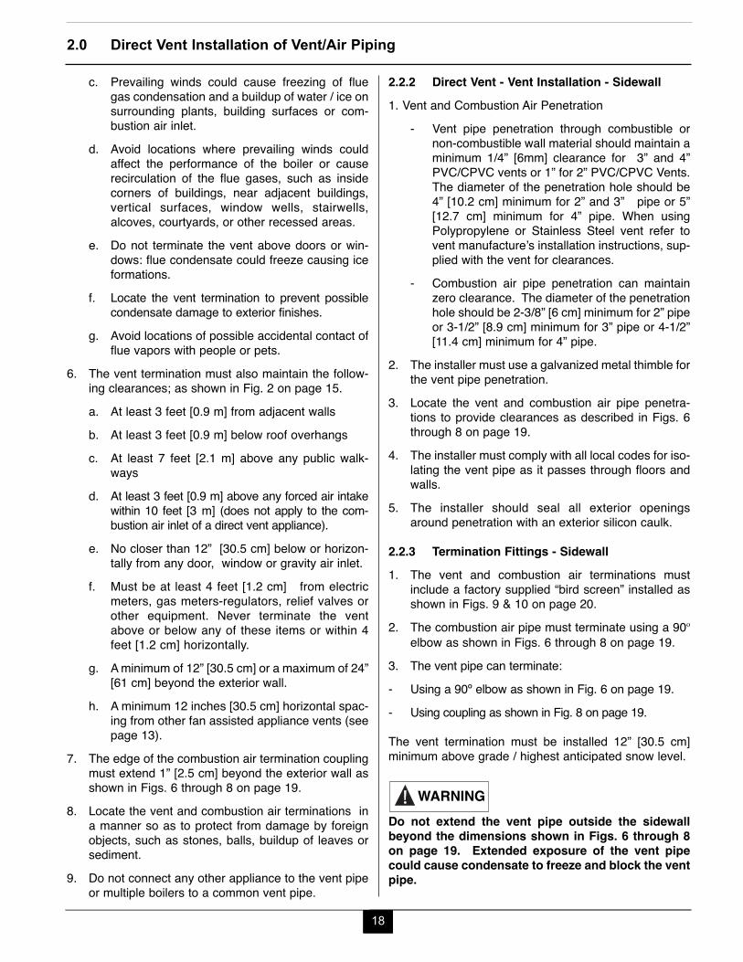
2.2.2 Direct Vent - Vent Installation - Sidewall1. Vent and Combustion Air Penetration
- Vent pipe penetration through combustible ornon-combustible wall material should maintain aminimum 1/4” [6mm] clearance for 3” and 4”PVC/CPVC vents or 1” for 2” PVC/CPVC Vents.The diameter of the penetration hole should be4” [10.2 cm] minimum for 2” and 3” pipe or 5”[12.7 cm] minimum for 4” pipe. When usingPolypropylene or Stainless Steel vent refer tovent manufacture’s installation instructions, sup-plied with the vent for clearances.
- Combustion air pipe penetration can maintainzero clearance. The diameter of the penetrationhole should be 2-3/8” [6 cm] minimum for 2” pipeor 3-1/2” [8.9 cm] minimum for 3” pipe or 4-1/2”[11.4 cm] minimum for 4” pipe.
2. The installer must use a galvanized metal thimble forthe vent pipe penetration.
3. Locate the vent and combustion air pipe penetra-tions to provide clearances as described in Figs. 6through 8 on page 19.
4. The installer must comply with all local codes for iso-lating the vent pipe as it passes through floors andwalls.
5. The installer should seal all exterior openingsaround penetration with an exterior silicon caulk.
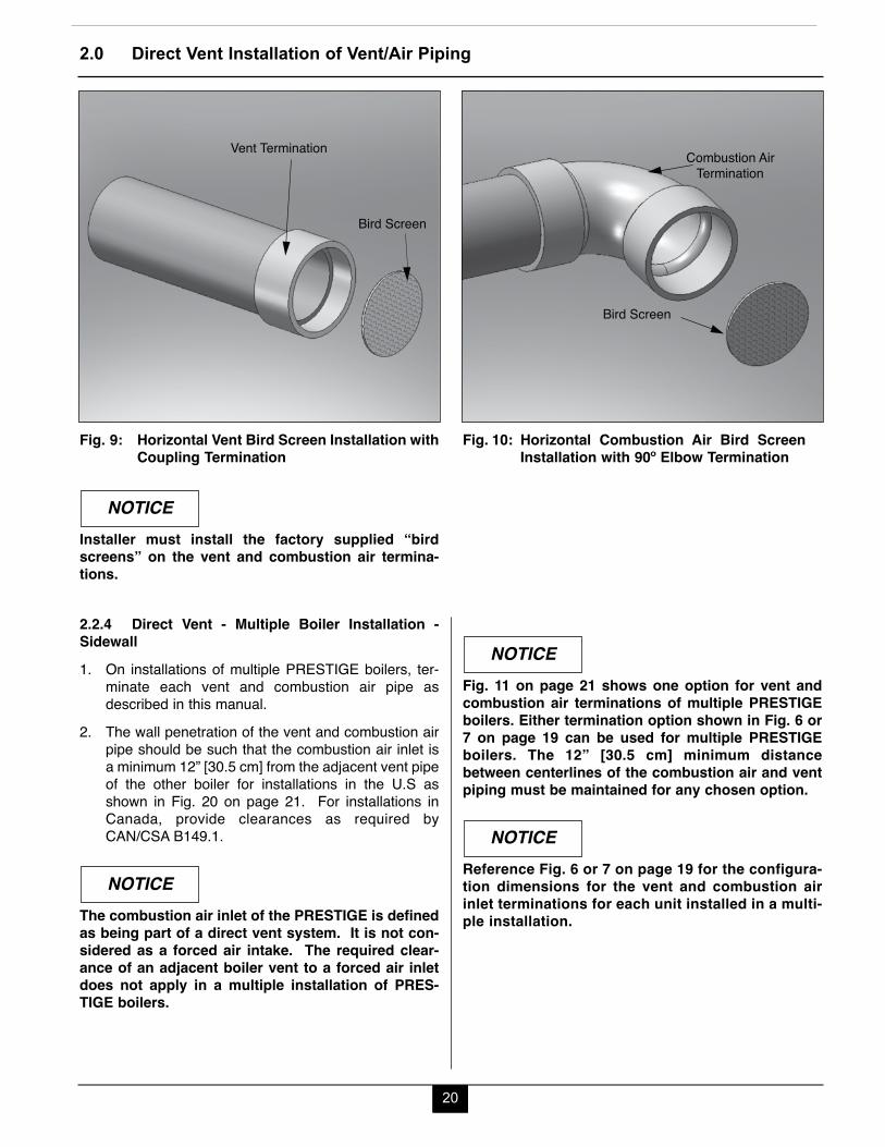
2.2.3 Termination Fittings - Sidewall1. The vent and combustion air terminations must
include a factory supplied “bird screen” installed asshown in Figs. 9 & 10 on page 20.
2. The combustion air pipe must terminate using a 90ºelbow as shown in Figs. 6 through 8 on page 19.
3. The vent pipe can terminate:- Using a 90º elbow as shown in Fig. 6 on page 19.- Using coupling as shown in Fig. 8 on page 19.
The vent termination must be installed 12” [30.5 cm]minimum above grade / highest anticipated snow level.
Do not extend the vent pipe outside the sidewallbeyond the dimensions shown in Figs. 6 through 8on page 19. Extended exposure of the vent pipecould cause condensate to freeze and block the ventpipe.
WARNING
2.0 Direct Vent Installation of Vent/Air Piping
19
2.0 Direct Vent Installation of Vent/Air Piping
12” Min. - 24” Max. [ 30.5 cm - 61 cm]From Wall To Vent
12" [
30.5
cm] M
in. A
bove
Gra
de /
High
est
Ant
icipa
ted
Snow
Lev
el
12" Max.
[30.5 cm]
12" Min.[30.5 cm]
12" Min. 24" Max.
[30.5 cm - 61 cm]
1" [2.5 cm] From Wall To Edge of Coupling - Air
Combustion AirTermination
Vent Termination
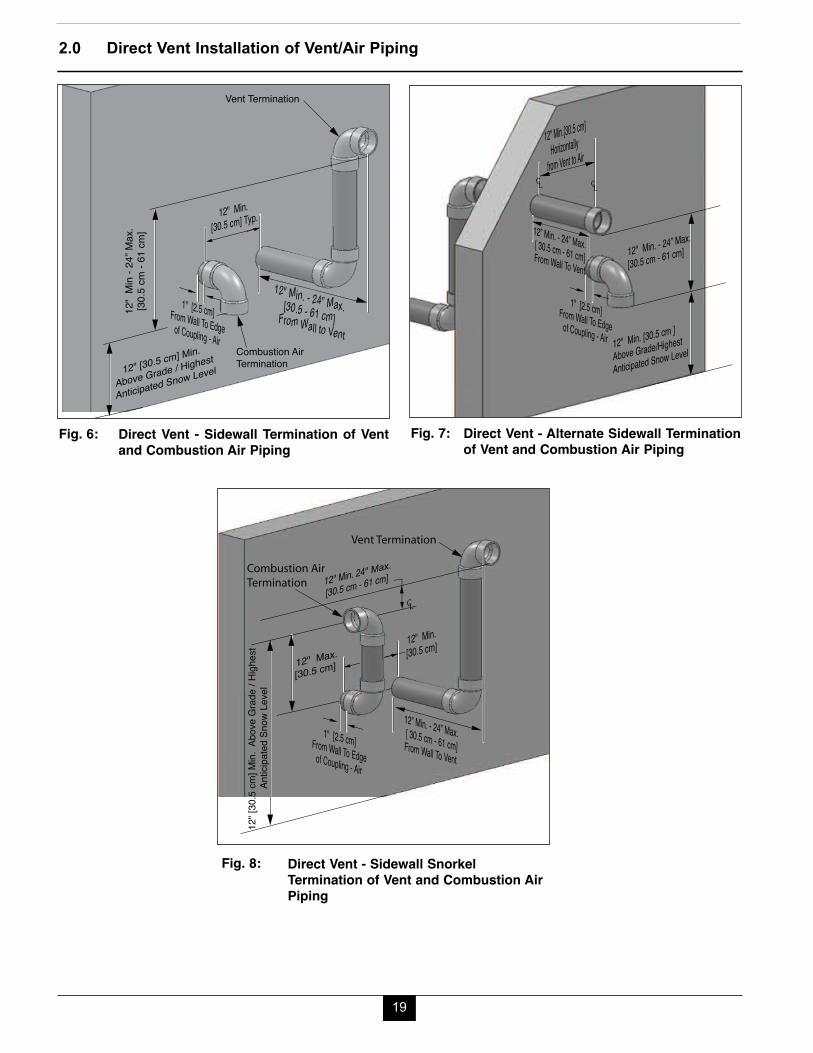
Direct Vent - Sidewall SnorkelTermination of Vent and Combustion AirPiping
Fig. 8:
Combustion AirTermination
12" Min. - 24” Max.[30.5 - 61 cm] From Wall to Vent
1" [2.5 cm] From Wall To Edge of Coupling - Air
12" [30.5 cm] Min.
Above Grade / Highest
Anticipated Snow Level
12" Min. [30.5 cm] Typ.
12"
Min
- 24”
Max
.[3
0.5
cm -
61 cm
]
Vent Termination
Direct Vent - Sidewall Termination of Ventand Combustion Air Piping
Fig. 6:
12" Min.[30.5 cm]Horizontally
from Vent to Air
1" [2.5 cm] From Wall To Edge of Coupling - Air
12” Min. - 24” Max. [ 30.5 cm - 61 cm] From Wall To Vent12" Min. - 24” Max.
[30.5 cm - 61 cm]
12" Min. [30.5 cm ]
Above Grade/Highest
Anticipated Snow Level
Direct Vent - Alternate Sidewall Terminationof Vent and Combustion Air Piping
Fig. 7:
20
2.0 Direct Vent Installation of Vent/Air Piping
2.2.4 Direct Vent - Multiple Boiler Installation -Sidewall1. On installations of multiple PRESTIGE boilers, ter-
minate each vent and combustion air pipe asdescribed in this manual.
2. The wall penetration of the vent and combustion airpipe should be such that the combustion air inlet isa minimum 12” [30.5 cm] from the adjacent vent pipeof the other boiler for installations in the U.S asshown in Fig. 20 on page 21. For installations inCanada, provide clearances as required byCAN/CSA B149.1.
The combustion air inlet of the PRESTIGE is definedas being part of a direct vent system. It is not con-sidered as a forced air intake. The required clear-ance of an adjacent boiler vent to a forced air inletdoes not apply in a multiple installation of PRES-TIGE boilers.
NOTICE
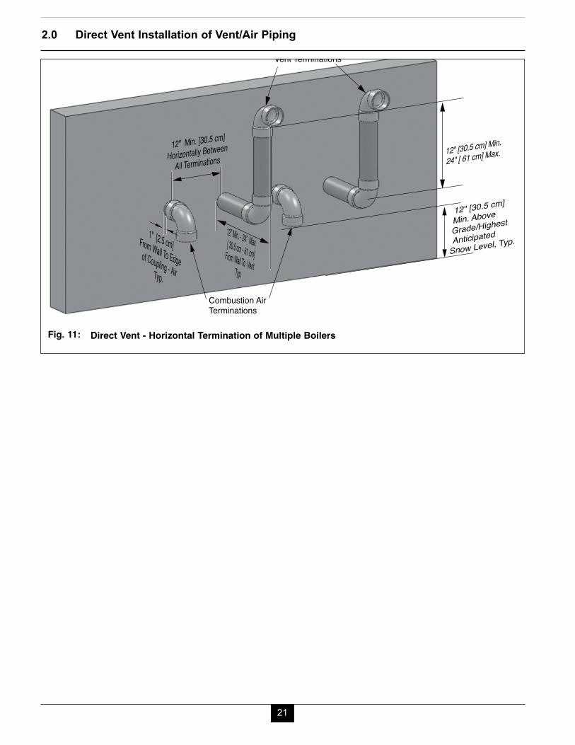
Fig. 11 on page 21 shows one option for vent andcombustion air terminations of multiple PRESTIGEboilers. Either termination option shown in Fig. 6 or7 on page 19 can be used for multiple PRESTIGEboilers. The 12” [30.5 cm] minimum distancebetween centerlines of the combustion air and ventpiping must be maintained for any chosen option.
Reference Fig. 6 or 7 on page 19 for the configura-tion dimensions for the vent and combustion airinlet terminations for each unit installed in a multi-ple installation.
NOTICE
NOTICE
Vent Termination
Bird Screen
Horizontal Vent Bird Screen Installation withCoupling Termination
Fig. 9:
Combustion Air Termination
Bird Screen
Horizontal Combustion Air Bird ScreenInstallation with 90º Elbow Termination
Fig. 10:
Installer must install the factory supplied “birdscreens” on the vent and combustion air termina-tions.
NOTICE
21
2.0 Direct Vent Installation of Vent/Air Piping
Combustion AirTerminations
Vent Terminations
24" [ 61 cm] Max. 12" [30.5 cm] Min.
12” Min. - 24” Max. [ 30.5 cm - 61 cm]From Wall To VentTyp.
1" [2.5 cm] From Wall To Edge of Coupling - AirTyp.
12" Min. [30.5 cm]
Horizontally Between All Terminations
12" [30.5 cm]
Min. Above Grade/Highest
Anticipated
Snow Level, Typ.
Direct Vent - Horizontal Termination of Multiple BoilersFig. 11:
22
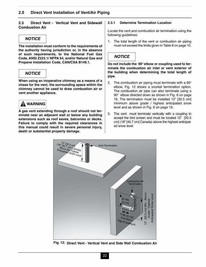
2.3 Direct Vent - Vertical Vent and SidewallCombustion Air
The installation must conform to the requirements ofthe authority having jurisdiction or, in the absenceof such requirements, to the National Fuel GasCode, ANSI Z223.1/ NFPA 54, and/or Natural Gas andPropane Installation Code, CAN/CSA B149.1.
When using an inoperative chimney as a means of achase for the vent, the surrounding space within thechimney cannot be used to draw combustion air orvent another appliance.
A gas vent extending through a roof should not ter-minate near an adjacent wall or below any buildingextensions such as roof eaves, balconies or decks.Failure to comply with the required clearances inthis manual could result in severe personal injury,death or substantial property damage.
NOTICE
NOTICE
WARNING
2.3.1 Determine Termination Location
Locate the vent and combustion air termination using thefollowing guidelines:1. The total length of the vent or combustion air piping
must not exceed the limits given in Table 8 on page 10.
Do not include the 90º elbow or coupling used to ter-minate the combustion air inlet or vent exterior ofthe building when determining the total length ofpipe.2. The combustion air piping must terminate with a 90º
elbow. Fig. 12 shows a snorkel termination option.The combustion air pipe can also terminate using a90º elbow directed down as shown in Fig. 6 on page19. The termination must be installed 12” [30.5 cm]minimum above grade / highest anticipated snowlevel and as shown in Fig. 6 on page 19.
3. The vent must terminate vertically with a coupling toaccept the bird screen and must be located 12” [30.5cm] (18” [45.7 cm] Canada) above the highest anticipat-ed snow level.
NOTICE
2.0 Direct Vent Installation of Vent/Air Piping
1" Min. [2.5 cm] From Wall To Edge of Coupling-Air
36" Max.[91.4 cm]
12"
[30.
5 cm
] Min.
Abo
ve
Grad
e / H
ighes
t A
ntici
pate
d Sn
ow L
evel
12" [30.5 cm] (18” [45.7 cm] Canada)Above the Highest
Anticipated Snow Level
Combustion Air Termination
Vent Termination
Direct Vent - Vertical Vent and Side Wall Combustion AirFig. 12:
23
2.0 Direct Vent Installation of Vent/Air Piping
4. The following should be considered when deter-mining the location of the vent and combustion airtermination:a. Locate the vent termination where flue vapors
will not damage surrounding shrubs, plants orair conditioning equipment or be objectionableto the homeowner.
b. The flue products will form a noticeable plume ofwater vapor as they condense in colder air.Avoid terminating the vent in areas where theplume could obstruct window views.
c. Prevailing winds could cause freezing of fluegas condensation and a buildup of water / ice onsurrounding plants, building surfaces or com-bustion air inlet.
d. Avoid locations where prevailing winds couldaffect the performance of the boiler or causerecirculation of the flue gases, such as insidecorners of buildings, near adjacent buildings,vertical surfaces, window wells, stairwells,alcoves, courtyards, or other recessed areas.
e. Do not terminate the vent above doors or win-dows: flue condensate could freeze causing iceformations.
f. Locate the vent termination to prevent possiblecondensate damage to exterior finishes.
g. Avoid locations of possible accidental contact offlue vapors with people or pets.
5. The vent termination must also maintain the follow-ing clearances; as shown in Fig. 2 on page 15.a. At least 3 feet [0.9 m] from adjacent wallsb. At least 3 feet [0.9 m] below roof over hangsc. At least 7 feet [2.1 m] above any public walk-
waysd. At least 3 feet [0.9 m] above any forced air
intake within 10 feet [3 m] (does not apply to thecombustion air inlet of a direct vent appliance).
e. No closer than 12” [30.5 cm] below or horizon-tally from any door or window or gravity air inlet.
f. Must be at least 4 feet [1.2 m] from any electricmeters, gas meters-regulators, relief valves orother equipment. Never terminate the ventabove or below any of these items within 4 feet[1.2 m] horizontally.
6. The edge of the combustion air termination couplingmust extend to 1” [2.5 cm] beyond the exterior wall,as shown in Fig. 12 page 22.
7. Locate the vent termination and combustion air inlet ina manner to protect from damage by foreign objects,such as stones, balls, or buildup of leaves or sediment.
8. Do not connect any other appliance to the vent pipeor multiple boilers to a common vent pipe.
2.3.2 Direct Vent - Vent Installation - Through theRoof1. Vent pipe penetration through combustible or non-
combustible wall material should maintain a mini-mum 1/4” [6 mm] clearance for 3” or 4” PVC/CPVCvents or 1” [2.5 cm] for 2” PVC/CPVC vents. Thediameter of the penetration hole should be 4” [10.2cm] minimum for 2” and 3” pipe or 5” [12.7 cm] min-imum for 4” pipe. When using Polypropylene orStainless Steel vent refer to the vent manufacture’sinstallation instructions, supplied with the vent forclearances.
2. The installer must use a galvanized metal thimble forthe vent pipe penetration.
3. The vent must terminate 12” [30.5 cm] (18” [45.7 cm]Canada) above the highest anticipated snow level.
4. The installer must comply with all local codes for iso-lating the vent pipe as it passes through floors, ceil-ings and roofs.
5. The installer should provide adequate flashing andsealing boots sized for the vent pipe.
2.3.3 Direct Vent - Combustion Air Installation -Sidewall1. Combustion air pipe penetration can maintain zero
clearance. The diameter of the penetration holeshould be 2 3/8” [6 cm] minimum for 2” pipe or 3 1/2”[8.9 cm] minimum for 3” pipe or 4 1/2” [11.4 cm] min-imum for 4” pipe.
2. The combustion air termination must be installed 12”[30.5 cm] minimum above grade / highest anticipat-ed snow level and as shown in Fig. 6 or 8 on page19.
3. The installer must comply with all local codes for iso-lating the combustion air pipe as it passes throughfloors and walls.
4. The installer should seal all exterior openingsaround penetration with an exterior silicon caulk.
24
2.0 Direct Vent Installation of Vent/Air Piping
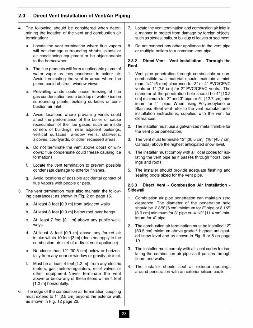
2.3.5 Direct Vent - Multiple Boiler Installation -Vertical Vent and Sidewall Combustion Air1. On installations of multiple PRESTIGE boilers, ter-
minate each vent and combustion air piping asdescribed in this manual.
2. Each vent and combustion air termination must be aminimum 12” [30.5 cm] from the adjacent termina-tion for installations in the U.S. as shown in Fig. 13.For installations in Canada, provide clearances asrequired by CAN/CSA B149.1.
The combustion air inlet of the PRESTIGE is definedas being part of a direct vent system. It is not con-sidered as a forced air intake. The required clear-ance of an adjacent boiler vent to a forced air inletdoes not apply in a multiple installation of PRES-TIGE boilers.
NOTICE
2.3.4 Termination Fittings - Vertical & Sidewall1. The vent and combustion air terminations must include
a factory supplied “bird screen” installed as shown inFig. 3 on page 16 & Fig. 10 on page 20.
2. The combustion air piping must terminate throughthe sidewall using a 90º elbow as shown in Fig. 6 or8 on page 19.
3. The vent piping must terminate vertically through theroof with a coupling to accept the bird screen andmust be located 12” [30.5 cm] (18” [45.7 cm]Canada) above the highest anticipated snow level.
Do not extend the vent pipe above the roof beyondthe dimension shown in Fig. 12 on page 22.Extended exposure of the vent pipe could causecondensate to freeze and block the vent pipe.
WARNING
12" Min.[30.5 cm]
36" Max. [91.4 cm]
12" Min.
[30.5 cm]
12" [3
0.5 cm
] Min.
Above
Grade
/ High
estAn
ticipat
ed Sn
ow Le
vel
12" [30.5 cm] (18” [45.7 cm] Canada) Above Highest Anticipated Snow Level Typ.
1" [2.5 cm]From Wall toEdge of Coupling-Air
Combustion Air Terminations
Vent Terminations
Direct Vent - Vertical Termination of Vent and SidewallTermination of Combustion Air of Multiple Boilers
Fig. 13:
25
3.0 Direct Vent Installation of Vent/Air Piping
SECTION III - CATEGORY IV (INDOOR AIR)INSTALLATION OF VENT/AIR PIPING
A Category IV appliance utilizes uncontaminated indoor oroutdoor air (surrounding the appliance) for combustion.
3.1 Category IV - Vertical - Through the Roofor Unused Chimney
The installation must conform to the requirements ofthe authority having jurisdiction or, in the absenceof such requirements, to the National Fuel GasCode, ANSI Z223.1/ NFPA 54, and/or Natural Gas andPropane Installation Code, CAN/CSA B149.1.
When using an inoperative chimney as a means of achase for the vent, the surrounding space within thechimney cannot be used to draw combustion air orvent another appliance.
A gas vent extending through a roof should not ter-minate near an adjacent wall or below any buildingextensions such as roof eaves, balconies or decks.Failure to comply with the required clearances inthis manual could result in severe personal injury,death or substantial property damage.
The information and diagrams outlining the fittingsand method of terminating the vent/combustion airare directly related to PVC/CPVC vent systems.When utilizing an AL 29-4C® or Polypropylene ventsystem there maybe some variations. Consult theappropriate vent manufacturer for recommenda-tions and clarifications.
3.1.1 Determine Termination Location
Locate the vent and combustion air termination using thefollowing guidelines:1. The total length of the vent must not exceed the limits
given in Table 8 on page 8.
WARNING
NOTICE
NOTICE
NOTICE
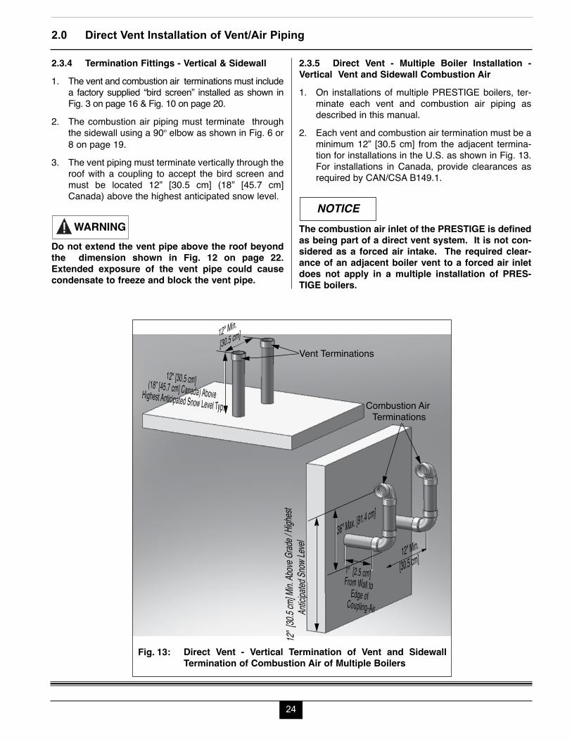
Do not include the coupling used to terminate thevent exterior of the building when determining thetotal length of pipe.2. The combustion air piping must terminate at the boil-
er with a 90º elbow.3. The vent must terminate vertically with a coupling
and must be located 12” [30.5 cm] (18” [45.7 cm]Canada) above the highest anticipated snow levelas shown in Fig. 14.
4. The following should be considered when determin-ing the location of the vent termination:a. Locate the vent termination where flue vapors
will not damage surrounding shrubs, plants orair conditioning equipment or be objectionableto the homeowner.
b. The flue products will form a noticeable plumeas they condense in colder air. Avoid terminat-ing the vent in areas where the plume couldobstruct window views.
c. Prevailing winds could cause freezing of fluecondensation and a buildup of water / ice on sur-rounding plants or building surfaces.
d. Avoid locations where prevailing winds couldaffect the performance of the boiler or causerecirculation of the flue gases, such as insidecorners of buildings or near adjacent buildingsor vertical surfaces, window wells, stairwells,alcoves, courtyards, or other recessed areas.
NOTICE
Vent Termination
12" [30.5 cm] (18” [45.7 cm] Canada)
Above the HighestAnticipated Snow Level
Category - IV - Vertical Termination ofVent Pipe
Fig. 14:
e. Do not terminate the vent above any doors orwindows: flue condensate could freeze causingice formations.
f. Locate the vent termination to prevent possiblecondensate damage to exterior finishes.
g. Avoid locations of possible accidental contact offlue vapors with people or pets.
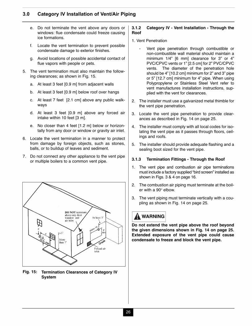
5. The vent termination must also maintain the follow-ing clearances; as shown in Fig. 15.a. At least 3 feet [0.9 m] from adjacent wallsb. At least 3 feet [0.9 m] below roof over hangsc. At least 7 feet [2.1 cm] above any public walk-
waysd. At least 3 feet [0.9 m] above any forced air
intake within 10 feet [3 m].e. No closer than 4 feet [1.2 m] below or horizon-
tally from any door or window or gravity air inlet.6. Locate the vent termination in a manner to protect
from damage by foreign objects, such as stones,balls, or to buildup of leaves and sediment.
7. Do not connect any other appliance to the vent pipeor multiple boilers to a common vent pipe.
3.1.2 Category IV - Vent Installation - Through theRoof1. Vent Penetration
- Vent pipe penetration through combustible ornon-combustible wall material should maintain aminimum 1/4” [6 mm] clearance for 3” or 4”PVC/CPVC vents or 1” [2.5 cm] for 2” PVC/CPVCvents. The diameter of the penetration holeshould be 4” [10.2 cm] minimum for 2” and 3” pipeor 5” [12.7 cm] minimum for 4” pipe. When usingPolypropylene or Stainless Steel Vent refer tovent manufactures installation instructions, sup-plied with the vent for clearances.
2. The installer must use a galvanized metal thimble forthe vent pipe penetration.
3. Locate the vent pipe penetration to provide clear-ances as described in Fig. 14 on page 25.
4. The installer must comply with all local codes for iso-lating the vent pipe as it passes through floors, ceil-ings and roofs.
5. The installer should provide adequate flashing and asealing boot sized for the vent pipe.
3.1.3 Termination Fittings - Through the Roof1. The vent pipe and combustion air pipe terminations
must include a factory supplied “bird screen” installed asshown in Figs. 3 & 4 on page 16.
2. The combustion air piping must terminate at the boil-er with a 90º elbow.
3. The vent piping must terminate vertically with a cou-pling as shown in Fig. 14 on page 25.
Do not extend the vent pipe above the roof beyondthe given dimensions shown in Fig. 14 on page 25.Extended exposure of the vent pipe could causecondensate to freeze and block the vent pipe.
WARNING
26
3.0 Category IV Installation of Vent/Air Piping
Termination Clearances of Category IVSystem
Fig. 15:
27
3.0 Category IV Installation of Vent/Air Piping
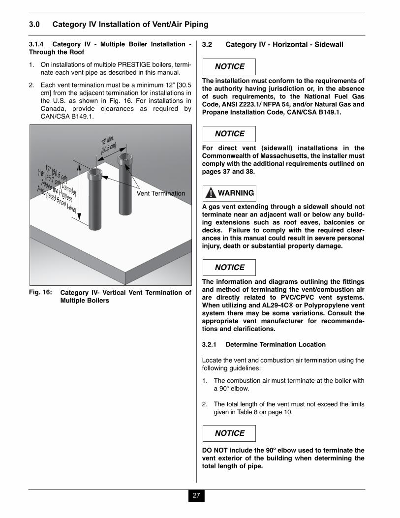
3.1.4 Category IV - Multiple Boiler Installation -Through the Roof1. On installations of multiple PRESTIGE boilers, termi-
nate each vent pipe as described in this manual.2. Each vent termination must be a minimum 12” [30.5
cm] from the adjacent termination for installations inthe U.S. as shown in Fig. 16. For installations inCanada, provide clearances as required byCAN/CSA B149.1.
3.2 Category IV - Horizontal - Sidewall
The installation must conform to the requirements ofthe authority having jurisdiction or, in the absenceof such requirements, to the National Fuel GasCode, ANSI Z223.1/ NFPA 54, and/or Natural Gas andPropane Installation Code, CAN/CSA B149.1.
For direct vent (sidewall) installations in theCommonwealth of Massachusetts, the installer mustcomply with the additional requirements outlined onpages 37 and 38.
A gas vent extending through a sidewall should notterminate near an adjacent wall or below any build-ing extensions such as roof eaves, balconies ordecks. Failure to comply with the required clear-ances in this manual could result in severe personalinjury, death or substantial property damage.
The information and diagrams outlining the fittingsand method of terminating the vent/combustion airare directly related to PVC/CPVC vent systems.When utilizing and AL29-4C® or Polypropylene ventsystem there may be some variations. Consult theappropriate vent manufacturer for recommenda-tions and clarifications.
3.2.1 Determine Termination Location
Locate the vent and combustion air termination using thefollowing guidelines:1. The combustion air must terminate at the boiler with
a 90º elbow.
2. The total length of the vent must not exceed the limitsgiven in Table 8 on page 10.
DO NOT include the 90º elbow used to terminate thevent exterior of the building when determining thetotal length of pipe.
NOTICE
NOTICE
WARNING
NOTICE
NOTICE
Vent Termination
12" [30.5 cm] (18” [45.7 cm] Canada)
Above the HighestAnticipated Snow Level
12" Min.
[30.5 cm]
Category IV- Vertical Vent Termination ofMultiple Boilers
Fig. 16:
28
3.0 Category IV Installation of Vent/Air Piping
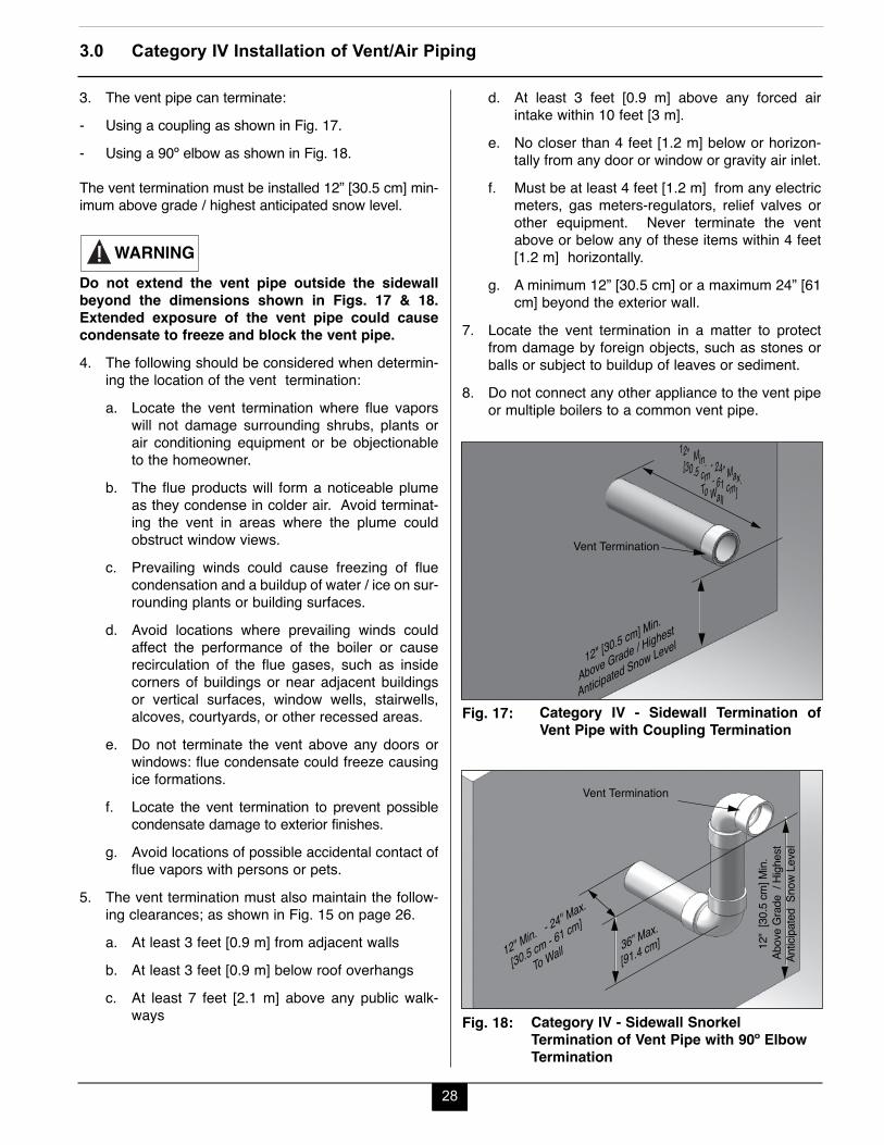
3. The vent pipe can terminate:- Using a coupling as shown in Fig. 17.- Using a 90º elbow as shown in Fig. 18.
The vent termination must be installed 12” [30.5 cm] min-imum above grade / highest anticipated snow level.
Do not extend the vent pipe outside the sidewallbeyond the dimensions shown in Figs. 17 & 18.Extended exposure of the vent pipe could causecondensate to freeze and block the vent pipe.4. The following should be considered when determin-
ing the location of the vent termination:a. Locate the vent termination where flue vapors
will not damage surrounding shrubs, plants orair conditioning equipment or be objectionableto the homeowner.
b. The flue products will form a noticeable plumeas they condense in colder air. Avoid terminat-ing the vent in areas where the plume couldobstruct window views.
c. Prevailing winds could cause freezing of fluecondensation and a buildup of water / ice on sur-rounding plants or building surfaces.
d. Avoid locations where prevailing winds couldaffect the performance of the boiler or causerecirculation of the flue gases, such as insidecorners of buildings or near adjacent buildingsor vertical surfaces, window wells, stairwells,alcoves, courtyards, or other recessed areas.
e. Do not terminate the vent above any doors orwindows: flue condensate could freeze causingice formations.
f. Locate the vent termination to prevent possiblecondensate damage to exterior finishes.
g. Avoid locations of possible accidental contact offlue vapors with persons or pets.
5. The vent termination must also maintain the follow-ing clearances; as shown in Fig. 15 on page 26.a. At least 3 feet [0.9 m] from adjacent wallsb. At least 3 feet [0.9 m] below roof overhangsc. At least 7 feet [2.1 m] above any public walk-
ways
WARNING
d. At least 3 feet [0.9 m] above any forced airintake within 10 feet [3 m].
e. No closer than 4 feet [1.2 m] below or horizon-tally from any door or window or gravity air inlet.
f. Must be at least 4 feet [1.2 m] from any electricmeters, gas meters-regulators, relief valves orother equipment. Never terminate the ventabove or below any of these items within 4 feet[1.2 m] horizontally.
g. A minimum 12” [30.5 cm] or a maximum 24” [61cm] beyond the exterior wall.
7. Locate the vent termination in a matter to protectfrom damage by foreign objects, such as stones orballs or subject to buildup of leaves or sediment.
8. Do not connect any other appliance to the vent pipeor multiple boilers to a common vent pipe.
12" Min. - 24” Max.[30.5 cm - 61 cm] To Wall
12" [30.5 cm] Min.
Above Grade / Highest
Anticipated Snow Level
Vent Termination
Category IV - Sidewall Termination ofVent Pipe with Coupling Termination
Fig. 17:
12"
[30.
5 cm
] Min.
Abo
ve G
rade
/ Hi
ghes
tAn
ticipa
ted
Sno
w Le
vel
12" Min. - 24" Max.
[30.5 cm - 61 cm]
To Wall 36” Max.
[91.4 cm]
Vent Termination
Category IV - Sidewall SnorkelTermination of Vent Pipe with 90º ElbowTermination
Fig. 18:
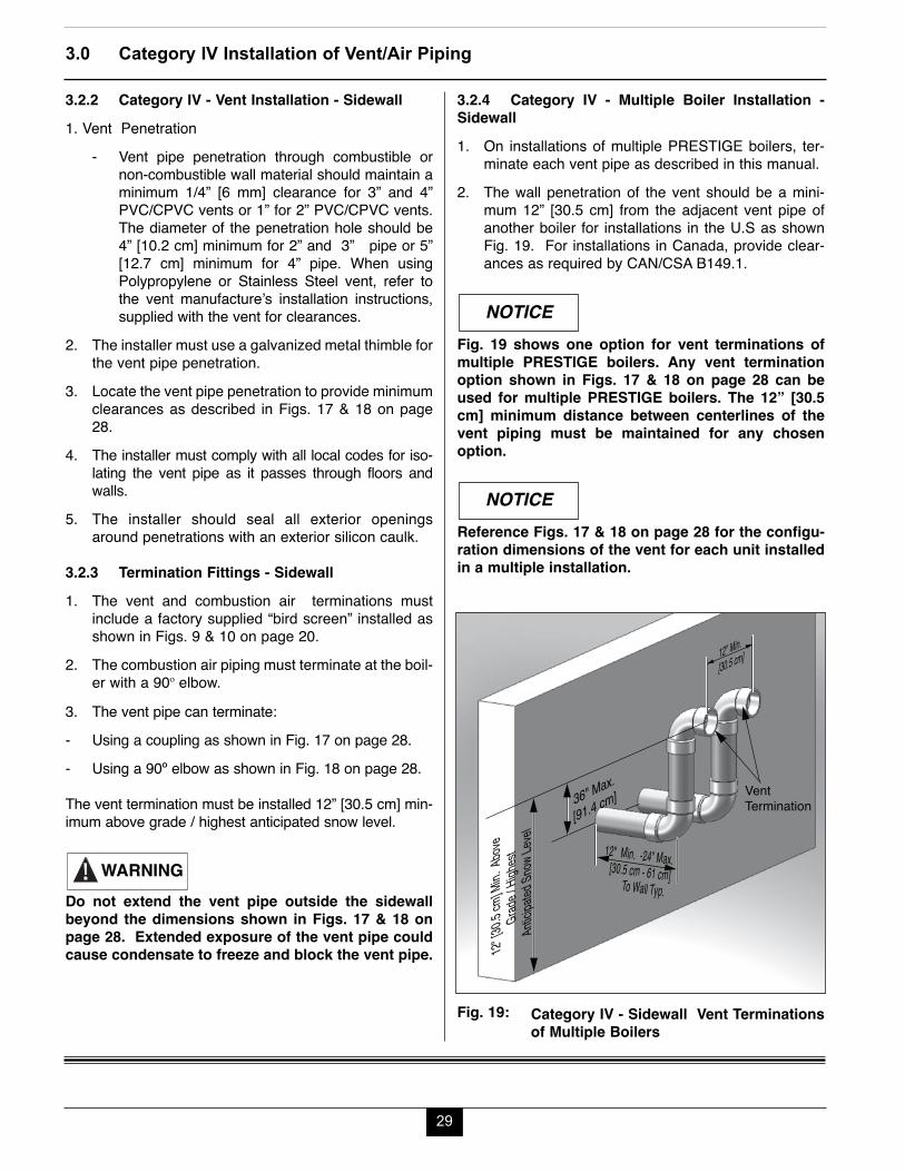
29
3.0 Category IV Installation of Vent/Air Piping
3.2.4 Category IV - Multiple Boiler Installation -Sidewall1. On installations of multiple PRESTIGE boilers, ter-
minate each vent pipe as described in this manual.2. The wall penetration of the vent should be a mini-
mum 12” [30.5 cm] from the adjacent vent pipe ofanother boiler for installations in the U.S as shownFig. 19. For installations in Canada, provide clear-ances as required by CAN/CSA B149.1.
Fig. 19 shows one option for vent terminations ofmultiple PRESTIGE boilers. Any vent terminationoption shown in Figs. 17 & 18 on page 28 can beused for multiple PRESTIGE boilers. The 12” [30.5cm] minimum distance between centerlines of thevent piping must be maintained for any chosenoption.
Reference Figs. 17 & 18 on page 28 for the configu-ration dimensions of the vent for each unit installedin a multiple installation.
NOTICE
NOTICE
3.2.2 Category IV - Vent Installation - Sidewall1. Vent Penetration
- Vent pipe penetration through combustible ornon-combustible wall material should maintain aminimum 1/4” [6 mm] clearance for 3” and 4”PVC/CPVC vents or 1” for 2” PVC/CPVC vents.The diameter of the penetration hole should be4” [10.2 cm] minimum for 2” and 3” pipe or 5”[12.7 cm] minimum for 4” pipe. When usingPolypropylene or Stainless Steel vent, refer tothe vent manufacture’s installation instructions,supplied with the vent for clearances.
2. The installer must use a galvanized metal thimble forthe vent pipe penetration.
3. Locate the vent pipe penetration to provide minimumclearances as described in Figs. 17 & 18 on page28.
4. The installer must comply with all local codes for iso-lating the vent pipe as it passes through floors andwalls.
5. The installer should seal all exterior openingsaround penetrations with an exterior silicon caulk.
3.2.3 Termination Fittings - Sidewall1. The vent and combustion air terminations must
include a factory supplied “bird screen” installed asshown in Figs. 9 & 10 on page 20.
2. The combustion air piping must terminate at the boil-er with a 90º elbow.
3. The vent pipe can terminate:- Using a coupling as shown in Fig. 17 on page 28.- Using a 90º elbow as shown in Fig. 18 on page 28.
The vent termination must be installed 12” [30.5 cm] min-imum above grade / highest anticipated snow level.
Do not extend the vent pipe outside the sidewallbeyond the dimensions shown in Figs. 17 & 18 onpage 28. Extended exposure of the vent pipe couldcause condensate to freeze and block the vent pipe.
WARNING
12" [3
0.5 cm
] Min.
Above
Grad
e / Hi
ghest
Antici
pated
Snow
Level
Vent Termination
12" Min.
[30.5 cm]
36" Max.
[91.4 cm]
12" Min. -24” Max.[30.5 cm - 61 cm] To Wall Typ.
Category IV - Sidewall Vent Terminationsof Multiple Boilers
Fig. 19:
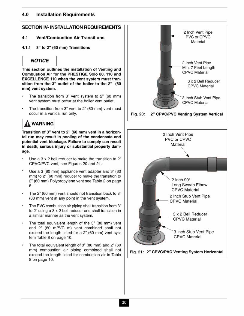
30
4.0 Installation Requirements
SECTION IV- INSTALLATION REQUIREMENTS
4.1 Vent/Combustion Air Transitions
4.1.1 3” to 2” (60 mm) Transitions
This section outlines the installation of Venting andCombustion Air for the PRESTIGE Solo 80, 110 andEXCELLENCE 110 when the vent system must tran-sition from the 3” outlet of the boiler to the 2” (60mm) vent system.• The transition from 3” vent system to 2” (60 mm)
vent system must occur at the boiler vent outlet.• The transition from 3” vent to 2” (60 mm) vent must
occur in a vertical run only.
Transition of 3” vent to 2” (60 mm) vent in a horizon-tal run may result in pooling of the condensate andpotential vent blockage. Failure to comply can resultin death, serious injury or substantial property dam-age.• Use a 3 x 2 bell reducer to make the transition to 2”
CPVC/PVC vent, see Figures 20 and 21.* Use a 3 (80 mm) appliance vent adapter and 3” (80
mm) to 2” (60 mm) reducer to make the transition to2” (60 mm) Polypropylene vent see Table 2 on page5.
• The 2” (60 mm) vent should not transition back to 3”(80 mm) vent at any point in the vent system.
• The PVC combustion air piping shall transition from 3”to 2” using a 3 x 2 bell reducer and shall transition ina similar manner as the vent system.
• The total equivalent length of the 3” (80 mm) ventand 2” (60 mPVC m) vent combined shall notexceed the length listed for a 2” (60 mm) vent sys-tem Table 8 on page 10.
• The total equivalent length of 3” (80 mm) and 2” (60mm) combustion air piping combined shall notexceed the length listed for combustion air in Table8 on page 10.
NOTICE
WARNING
2 Inch Vent PipePVC or CPVC
Material
2 Inch Vent PipeMin. 7 Feet LengthCPVC Material
3 x 2 Bell ReducerCPVC Material
3 Inch Stub Vent PipeCPVC Material
2” CPVC/PVC Venting System VerticalFig. 20:
2 Inch Vent PipePVC or CPVC
Material
2 Inch Stub Vent PipeCPVC Material
2 Inch 90º Long Sweep ElbowCPVC Material
3 x 2 Bell ReducerCPVC Material
3 Inch Stub Vent PipeCPVC Material
2” CPVC/PVC Venting System HorizontalFig. 21:

31
4.0 Installation Requirements
4.1.2 3” to 4” (100 mm) Transitions
This section outlines the installation of Venting andCombustion Air for the PRESTIGE Solo 80, 110, 155,175, 250 and EXCELLENCE 110 when the vent sys-tem must transition from the 3” outlet of the boiler tothe 4” (100 mm) vent system.• The transition from 3” vent system to 4” (100 mm) vent
system must occur within 5 feet [1.5 m] of the boilervent outlet.
• The transition from 3” vent to 4” (100 mm) vent mustoccur in a vertical run only.
Transition of 3” vent to 4” (100 mm) vent in a hori-zontal run may result in pooling of the condensateand potential vent blockage. Failure to comply canresult in death, serious injury or substantial propertydamage.• The 4” (100 mm) vent should not transition back to
3” (80 mm) vent at any point in the vent systemexcept when using ACV - Triangle Tube’s optionalPVC concentric vent termination kit, see kit instruc-tions for details.
• The combustion air piping shall transition from 3” to4” (100 mm) in the same manner as the vent sys-tem.
• The total equivalent length of the 3” (80 mm) ventand 4” (100 mm) vent combined shall not exceed thelength listed for a 4” (100 mm) vent system Table 8on page 10.
• The total equivalent length of 3” (80 mm) and 4”(100 mm) combustion air piping combined shall notexceed the length listed for combustion air in Table8 on page 10.
WARNING
NOTICE
4.2 Insert Piping to PRESTIGE Adapters1. The installer must clean, deburr and chamfer the
pipe ends.
The pipe ends must be smooth, free of sharp edgeschamfer and wiped clean to prevent possible dam-age to the sealing gasket in the vent and combustionair adapters. Failure to comply with this require-ment could result in leakage of flue products caus-ing possible severe personal injury or death.2. Prior to inserting the pipe, inspect the vent and com-
bustion air adapters to verify there are no obstruc-tions or packing material inside the adapters and thegaskets are in place.
3. Ensure the adapter banding strap is loose prior toinserting the pipe.
4. Apply a small amount of silicon grease or water tothe insertion end of the pipe to ease insertion intothe adapter.
5. Insert the pipe into the adapter until it is fully seated.
Do not apply excessive force, twist or bend theadapter or vent / combustion air pipe when insert-ing. The adapter gasket could be damaged resultingin possible flue gas leakage.
6. Secure the vent and combustion air pipe by tighten-ing the adapter banding strap. Do not over tightenthe strap. The seal is made with gasket inside theadapter.
WARNING
WARNING
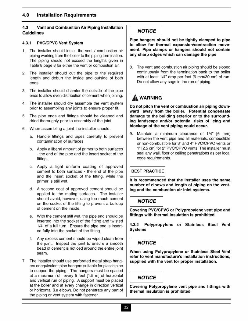
Pipe hangers should not be tightly clamped to pipeto allow for thermal expansion/contraction move-ment. Pipe clamps or hangers should not containany sharp edges which can damage the pipe
8. The vent and combustion air piping should be slopedcontinuously from the termination back to the boilerwith at least 1/4” drop per foot [6 mm/30 cm] of run.Do not allow any sags in the run of piping.
Do not pitch the vent or combustion air piping down-ward away from the boiler. Potential condensatedamage to the building exterior or to the surround-ing landscape and/or potential risks of icing andblockage of the vent piping could occur.9. Maintain a minimum clearance of 1/4” [6 mm]
between the vent pipe and all materials, combustibleor non-combustible for 3” and 4” PVC/CPVC vents or1” [2.5 cm] for 2” PVC/CPVC vents. The installer mustseal any wall, floor or ceiling penetrations as per localcode requirements.
It is recommended that the installer uses the samenumber of elbows and length of piping on the vent-ing and the combustion air inlet systems.
Covering PVC/CPVC or Polypropylene vent pipe andfittings with thermal insulation is prohibited.
4.3.2 Polypropylene or Stainless Steel VentSystems
When using Polypropylene or Stainless Steel Ventrefer to vent manufacture’s installation instructions,supplied with the vent for proper installation.
Covering Polypropylene vent pipe and fittings withthermal insulation is prohibited.
NOTICE
WARNING
BEST PRACTICE
NOTICE
NOTICE
NOTICE
32
4.3 Vent and Combustion Air Piping InstallationGuidelines
4.3.1 PVC/CPVC Vent System1. The installer should install the vent / combustion air
piping working from the boiler to the piping termination.The piping should not exceed the lengths given inTable 8 page 8 for either the vent or combustion air.
2. The installer should cut the pipe to the requiredlength and deburr the inside and outside of bothends.
3. The installer should chamfer the outside of the pipeends to allow even distribution of cement when joining.
4. The installer should dry assemble the vent systemprior to assembling any joints to ensure proper fit.
5. The pipe ends and fittings should be cleaned anddried thoroughly prior to assembly of the joint.
6. When assembling a joint the installer should:a. Handle fittings and pipes carefully to prevent
contamination of surfacesb. Apply a liberal amount of primer to both surfaces
- the end of the pipe and the insert socket of thefitting.
c. Apply a light uniform coating of approvedcement to both surfaces - the end of the pipeand the insert socket of the fitting, while theprimer is still wet.
d. A second coat of approved cement should beapplied to the mating surfaces. The installershould avoid, however, using too much cementon the socket of the fitting to prevent a buildupof cement on the inside.
e. With the cement still wet, the pipe end should beinserted into the socket of the fitting and twisted1/4 of a full turn. Ensure the pipe end is insert-ed fully into the socket of the fitting.
f. Any excess cement should be wiped clean fromthe joint. Inspect the joint to ensure a smoothbead of cement is noticed around the entire jointseam.
7. The installer should use perforated metal strap hang-ers or equivalent pipe hangers suitable for plastic pipeto support the piping. The hangers must be spacedat a maximum of every 5 feet [1.5 m] of horizontaland vertical run of piping. A support must be placedat the boiler and at every change in direction verticalor horizontal (i.e elbow). Do not penetrate any part ofthe piping or vent system with fastener.
4.0 Installation Requirements
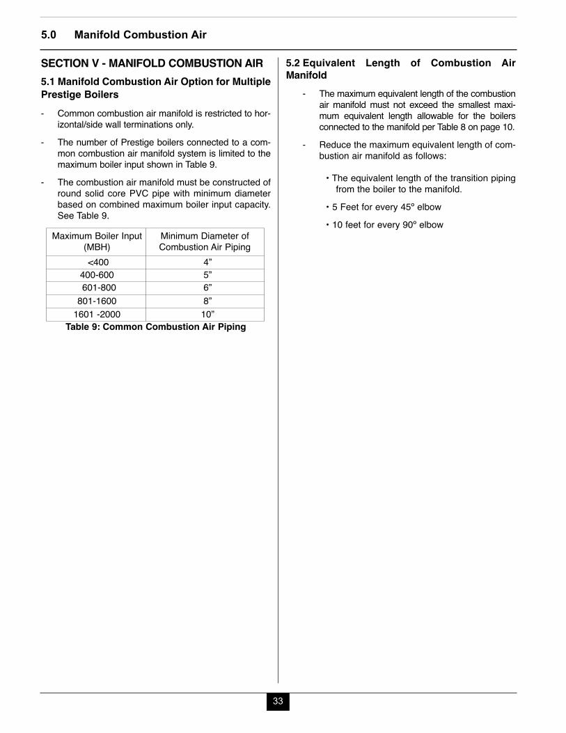
33
5.0 Manifold Combustion Air
SECTION V - MANIFOLD COMBUSTION AIR5.1 Manifold Combustion Air Option for MultiplePrestige Boilers- Common combustion air manifold is restricted to hor-
izontal/side wall terminations only.- The number of Prestige boilers connected to a com-
mon combustion air manifold system is limited to themaximum boiler input shown in Table 9.
- The combustion air manifold must be constructed ofround solid core PVC pipe with minimum diameterbased on combined maximum boiler input capacity.See Table 9.
Table 9: Common Combustion Air Piping
5.2 Equivalent Length of Combustion AirManifold
- The maximum equivalent length of the combustionair manifold must not exceed the smallest maxi-mum equivalent length allowable for the boilersconnected to the manifold per Table 8 on page 10.
- Reduce the maximum equivalent length of com-bustion air manifold as follows:
• The equivalent length of the transition pipingfrom the boiler to the manifold.
• 5 Feet for every 45º elbow• 10 feet for every 90º elbow
Maximum Boiler Input(MBH)
Minimum Diameter ofCombustion Air Piping
<400 4”400-600 5”601-800 6”
801-1600 8”1601 -2000 10”
34
5.0 Manifold Combustion Air
5.3 Horizontal Air Termination- The common combustion air manifold must termi-
nate on a horizontal/side wall using a 90 degreeelbow pointed downward.
- The inlet of the common combustion air terminationelbow must include a corrosion resistant field sup-plied bird screen.
- The edge of the combustion air termination cou-pling must extend 1” (2.5 cm) beyond the finishedexterior wall as shown in Fig. 6 on page 19.
- The bottom of the common combustion air termi-nation (inlet) must be located 12” (30.5 cm) mini-mum above grade/highest anticipated snow level.
- The common combustion air termination must be aminimum of 3 feet (0.9 m) below (vertically) anyappliance vent termination within 10 feet (3 m) hor-izontally.
- The common combustion air termination must be aminimum of 3 feet (0.9 m) horizontally from anyappliance vent termination.
- Avoid locating the common combustion air termi-nation in a location where prevailing winds couldaffect the performance of the boilers or cause recir-culation of flue gases, such as inside corners ofbuildings, near adjacent buildings, vertical surfaces,window wells, stairwells, alcoves, courtyards, orother recessed areas. The common air terminationmust be installed a minimum of 6 feet horizontallyfrom any such locations.
- Locate the combustion air termination in a mannerso as to protect from damage from foreign objects,such as stones, balls, buildup of leaves or sedi-ment.
5.4 Installation Guidelines- Use perforated metal strap hangers or equivalent
pipe hangers suitable for plastic pipe to support thecommon air manifold. Hangers must be placed at amaximum of every 5 ft [1.5 m] of horizontal and ver-tical run of piping. A support must be placed at everyboiler and at every change in direction vertically orhorizontally.
35
5.0 Manifold Combustion Air
5.5 Transition Boiler Air Piping to ManifoldGuidelines- The transitions piping from the boiler adapter to the
combustion air manifold must be 3 inch or 4 inchpipe.
- Reference Table 8 on page 10 for reductions inallowable equivalent lengths.
To maintain the maximum allowable equivalent lengthof the combustion air manifold, keep the boiler tran-sition vent piping to a minimum using the leastamount of fittings and pipe lengths as possible.
BEST PRACTICE
SECTION VI - COMMONWEALTH OFMASSACHUSETTS
6.1 Installations with the Direct VentTermination Elevation At or Below 4 feet ofGrade
The following instructions apply to the installation ofa direct vented appliance whose vent terminationand combustion air inlet are installed at or below afour foot elevation (above the grade).1. If not already present in the structure of the building,
a carbon monoxide detector and alarm must beinstalled in the living area outside the bedroom(s).The carbon monoxide detector and alarm is provid-ed by the installer.
The carbon monoxide detector and alarm installed inthe living space outside the bedrooms shall complywith NFPA 720 (2005 edition).2. A carbon monoxide detector and alarm shall be
installed in the mechanical room in which the directvent appliance is located. The carbon monoxidedetector and alarm shall:• Be installed on the same 120 volt service circuit
as the appliance such that only one serviceswitch services both the appliance and the car-bon monoxide detector.
• Provide battery back-up power in case of powerfailure
The carbon monoxide detector and alarm installedwithin the same room as the direct vent appliancemust meet ANSI/UL 2034 standards and comply withNFPA 720 (2005 edition). The carbon monoxidedetector and alarm must be tested, approved andlisted with a Nationally Recognized Testing Lab asrecognized under 527 cm.3. The direct vent termination must be approved for the
appliance and when applicable the combustion airinlet must be approved for the appliance.Installation of the vent termination and combustionair inlet shall be in strict compliance with the instal-lation instructions provided with the appliance.
NOTICE
NOTICE
NOTICE
36
6.0 Commonwealth of Massachusetts
The installer must leave the appliance installationmanual and any documentation regarding the instal-lation of the venting, vent termination and combus-tion air inlet with the appliance upon completion ofthe installation.4. A metal or plastic identification plate (provided by the
installer) must be mounted on the exterior wall of thebuilding 4 feet directly above the location of the venttermination and combustion air inlet. The identifica-tion plate shall read “Gas Vent Directly Below”.The size of the plate and lettering shall be of suffi-cient size to be easily read from a distance of 8 feet.
NOTICE
37
6.2 Installations with the Direct VentTermination Elevation Above 4 feet of Grade:
The following instructions apply to the installation ofa direct vented appliance whose vent terminationand combustion air inlet are installed above a fourfoot elevation above the grade.1. If not already present in the structure of the building,
a carbon monoxide detector and alarm must beinstalled in the living area outside the bedroom(s).The carbon monoxide detector and alarm is provid-ed by the installer.
The carbon monoxide detector and alarm installed inthe living space outside the bedrooms must complywith NFPA 720 (2005 edition).2. A carbon monoxide detector and alarm shall be
installed in the mechanical room in which the directvent appliance is located. The carbon monoxidedetector and alarm shall:• Be either hard wired or battery powered or both.
NOTICE
NOTICE
6.0 Commonwealth of Massachusetts
The carbon monoxide detector and alarm installedwithin the same room as the direct vent appliancemust comply with NFPA 720 (2005 edition).
3. The direct vent termination must be approved for theappliance and when applicable the combustion airinlet must be approved for the appliance.Installation of the vent termination and combustionair inlet shall be in strict compliance with the instal-lation instructions provided with the appliance.
The installer must leave the appliance installationmanual and any documentation regarding the instal-lation of the venting, vent termination and combus-tion air inlet with the appliance upon completion ofthe installation.
NOTICE
NOTICE
38
Notes:
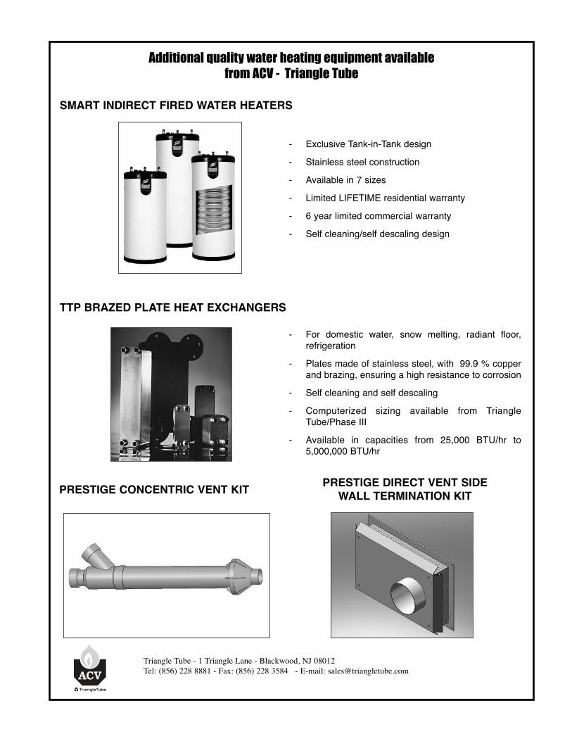
Additional quality water heating equipment available from ACV - Triangle Tube
SMART INDIRECT FIRED WATER HEATERS
TTP BRAZED PLATE HEAT EXCHANGERS
Triangle Tube - 1 Triangle Lane - Blackwood, NJ 08012Tel: (856) 228 8881 - Fax: (856) 228 3584 - E-mail: [email protected]
- For domestic water, snow melting, radiant floor,refrigeration
- Plates made of stainless steel, with 99.9 % copperand brazing, ensuring a high resistance to corrosion
- Self cleaning and self descaling- Computerized sizing available from Triangle
Tube/Phase III- Available in capacities from 25,000 BTU/hr to
5,000,000 BTU/hr
- Exclusive Tank-in-Tank design- Stainless steel construction- Available in 7 sizes - Limited LIFETIME residential warranty- 6 year limited commercial warranty- Self cleaning/self descaling design
PRESTIGE CONCENTRIC VENT KIT PRESTIGE DIRECT VENT SIDEWALL TERMINATION KIT