Embed Size (px)
Citation preview

1
PVE 4.0 Keurmerk Active and Passive
In-house materials Document name PVE Keurmerk v4.0 doc Document status Final
Project name Keurmerk Completion date 1 juli 2014
Classification Public Version no. V4.0
Author J.P. Cnossen NLkabel on behalf
of College of Experts
Number of pages 51
Location of File NLkabel
Lange Voorhout 90
2514 EJ Den Haag
Approved by R van Esch NLkabel
Signature
This document is the property of NLkabel and must not be reproduced or retransmitted in any form without express permission.
NLkabel does not accept responsibility for any errors or omissions within the document, or circulation of document updates information
2
Document information
Version control
Version Date Reason of update Initials
0.1 12-12-2007 First draft in document form. JL
0.2/b 07-02-2008 Adjustments in norm and specs JL
0.3 04-03-2008 Discussions at Veenendaal JL
0.4 12-03-2008 Last minor points JL
1.0 25-03-2008 Final version JL
1.1 07-05-2008 Additional information JW
1.2 08-05-2008 Appeal and use of logo JW
1.3 25-06-2008 Clarify some criteria JL
1.4 25-09-2008 Round one testing results JL/JW/JPC
1.5 01-12-2008 Remarks KEURMERKINSTITUUT (S. Stravers) inserted JPC
1.6 6-1-2009 Remarks CVD 12 December 2008 inserted JPC
2.0 23-2-2009 Correction page 17 footnote 10 inserted JPC
2.1 29-4-2009
Production change added in chapter 7 2nd
paragraph to make this article also applicable in
case of a new producer
3 dB relaxation allowance added as footnote 30
chapter 10.2
Clamping force F-connector changed footnote
81/82 in chapter 10.5
JPC
3.0 11-5-2010 General update and new products added JPC
3.1 15 -2-2011 Amendment process step added JPC
4.0 concept 24-5-2012 General update JPC
4.0 concept 2 20-9-2012 Update chapter 6,7,8 RdD
4.0 concept 3 13-2-2014 General update and review JPC
Reviewed by
Name Date Signature
“College van Deskundigen”:
Cok Arkestijn Ziggo
John Louwerse UPC NL
John Raeskin Technetix
Henk van Dok Hirschmann
Robert Schotman Hemmink
Arno Albright Teleste
Rogier den Dekker Keurmerkinstituut
Jelle Cnossen NLkabel
1-5-2014
p/o
3
Table of content
1 INTRODUCTION .................................................................................5
2 SCOPE ...............................................................................................6
3 DEFINITIONS AND NORMATIVE REFERENCES ......................................7 3.1 DEFINITIONS ......................................................................................... 7 3.2 NORMATIVE REFERENCES ........................................................................ 8
4 PROCEDURE: QUALIFYING FOR KABEL KEUR .......................................9 4.1 REQUIREMENTS ................................................................................... 11 4.2 APPLICATION ...................................................................................... 11 4.3 QUOTE .............................................................................................. 11 4.4 CERTIFICATION PROCEDURE ................................................................... 11 OPTION 1 .................................................................................................... 11 OPTION 2 .................................................................................................... 12 OPTION 3 .................................................................................................... 12 4.5 SAMPLES ............................................................................................ 12 4.6 PROTOTYPES ....................................................................................... 12 4.7 INTERMEDIATE RESULTS ........................................................................ 12 4.8 USE OF THE “KABEL KEUR” QUALITY MARK .............................................. 12 4.9 TRACE-ABILITY OF CERTIFIED PRODUCTS ................................................... 12 4.10 ANNUAL SURVEILLANCE ...................................................................... 12 4.11 RECERTIFICATION............................................................................... 13 4.12 LAYING AN APPEAL ............................................................................ 13
5 VALIDITY AND ABUSE ...................................................................... 14
6 ORGANISATION ............................................................................... 15
7 SPECIAL PRODUCTS ......................................................................... 17
8 GENERAL REQUIREMENTS, LABELING AND PACKAGING .................... 18 8.1 GENERAL REQUIREMENTS ..................................................................... 18 8.2 PRODUCT LABELING AND PACKAGING REQUIREMENTS ................................ 19
9 PASSIVE COMPONENTS.................................................................... 21 9.1 WALL OUTLET ..................................................................................... 21 9.2 TWO WAY SPLITTERS ............................................................................ 22 9.3 CABLE ................................................................................................ 23
9.3.1 Cable (equipment fly-lead) ...................................................... 23 9.3.2 Coax installation cable (indoor mounting cable) .................... 24 9.3.3 Coax 9 (indoor mounting cable) ............................................. 25
9.4 CONNECTORS AND ADAPTORS ................................................................ 27 9.4.1 IEC and F connectors and adaptors ........................................ 27
9.5 DIPLEX FILTER ..................................................................................... 27 9.6 PORT TERMINATOR .............................................................................. 28 9.7 HDMI CABLE ...................................................................................... 29 9.8 UTP PATCH CABLE ............................................................................... 30
10 ACTIVE COMPONENTS ................................................................... 31 10.1 AMPLIFIER ........................................................................................ 31

4
10.2 AMPLIFIER ........................................................................................ 33
11 SPECIAL PRODUCTS ....................................................................... 36
12 APPENDIX A: LOGO’S ..................................................................... 37
13 APPENDIX B: F-CONNECTORS ........................................................ 39
14 APPENDIX C: IEC-CONNECTORS ..................................................... 42
15 APPENDIX D: CABLE CLAMP ........................................................... 46
16 APPENDIX E: PULL FORCE IEC FEMALE CONNECTOR ........................ 49
17 APPENDIX F: MEASUREMENT PROTOCOL FERRITE HDMI CABLE ...... 50
18 APPENDIX G .................................................................................. 52
5
1 Introduction NLkabel, the association of Dutch cable providers, has issued a quality certification mark for in-house cabling
system components under the brand name “Kabel Keur”. Kabel Keur’s goal is to help consumers find and select
coaxial cables, splitters, connectors and amplifiers with a quality level that equals or exceeds specification
limits set by Kabel Keur. The specifications are set to enable subscribers to enjoy uninterrupted cable services
including state-of-the-art multimedia services offered by Dutch cable providers.
The growing number of services demands high performance in-house cabling-systems to meet the necessary
high quality of service. Frequently in-house cabling-systems, with components such as coaxial cables, splitters,
connectors and amplifiers have become obsolete and are a cause of a reduced quality of service to the
subscriber. The subscriber can perceive this as a poor quality of the service provided by the cable provider,
though the cause is mostly the subscriber’s poor quality in-home network.
To guide consumers to buy qualified products and materials within a broader market of (sometimes inferior)
products, the Dutch cable providers, united in NLkabel (their trade organization) have now introduced the
quality mark “Kabel Keur”. “Kabel Keur” identifies independently inspected and approved materials and
products. Only materials and products, which have passed approval tests successfully, get the qualification
mark “Kabel Keur”.
To create awareness of the Kabel Keur quality mark and its benefits, cable providers promote the certified
products by means of several promotional activities, amongst that the Internet site www.Kabelkeur.nl.
To qualify for certification a manufacturer or trader can ask the Keurmerkinstituut to investigate and test its
products. The Keurmerkinstituut is an independent accredited agency, selected by NLkabel, and well equipped
to ensure that the certification procedure is operated according to the “Kabel Keur” mark rules and
regulations. The requesting supplier hands over a completed application form. By handing over this form the
requesting supplier enters into consent with NLkabel and Keurmerkinstituut. This consent regulates the full
process of acquiring and applying the “Kabel Keur” certification mark. Requesting suppliers bear the costs
involved. Application forms can be downloaded from www.keurmerk.nl.
The PVE is a dynamic document. At least once a year a college of experts (CVD) and Keurmerkinstituut decide if
the document needs editing to assure that consumers get the quality of products to assure a high quality of
service. Proposed alterations are announced and discussed with the participating partners before becoming
operational. For all products, both for new products and for products that already received a “Kabel Keur”
certification mark, there is a 3-year transition period. It is preferred that new products comply with the latest
PVE requirements from the start.
In order to keep up with technical developments and respond to new requirements an amendment to the
current PVE can be issued by the college of Experts (CVD). This amendment will be published on the
Keurmerkinstituut website and will be distributed directly to the participating manufacturers and traders. The
legal impact of the amendment is equal to that of the corresponding PVE. The amendment is considered to be
an integral part of the current PVE.

6
2 Scope
Kabel Keur is a private quality mark for components for a multimedia network. Kabel Keur is applicable to
components defined in this document, meant for in-house home networks. A home network that meets the
Kabel Keur requirements is suitable for the Dutch cable market.
7
3 Definitions and normative references 3.1 Definitions
“Kabel Keur” “Kabel Keur” is a certification mark. Products carrying this mark as a label
enable, if applied properly, the construction of a high quality in-home
Multimedia network that consumers have no need to complain about.
Consumer packaging A packaging for end-user application.
Factory packaging A packaging for private label companies and installation contractors. Not
for end-user sale / resell purposes.
Coaxial cable Asymmetrical cable that is in this context the most suitable transport
medium for Multimedia signals of a broad frequency spectrum.
Wall outlet A device to connect the customer equipment to the fixed in-house
network.
Splitter A device that is a part of the connection between one source to two or
more destinations in a multimedia coaxial home network.
Connector A device that connects a coaxial cable to a source or a destination in a
multimedia home network.
Adaptor A device that enables matching between two connections.
Amplifier A device that is able to increase the signal level to cover larger distances
or/and to split the signal.
HDMI cable HDMI cable (High-Definition Multimedia Interface) is a compact cable for
transmitting uncompressed digital data.
Diplex filter A device that combines or separates frequency ranges.
Terminator A device that terminates a connection.
Special product A device specially designed for Dutch Cable Operators.
“Programma van Eisen”
(PVE-document)
Specifications that products have to meet to obtain the “Kabel Keur”
certification mark, as well as guidelines and instructions for the use of the
“Kabel Keur” Certification mark. The last version of the PVE is called the
current PVE.
Amendment Changes, additions to a PVE, being an integral part of the current PVE
Private label products Certified product that are sold under a different (private) label.
College of experts (CVD) Experts drafting the specifications (PVE document).
NLkabel The branch organization of Dutch cable providers.
Dutch Cable Operators Dutch Multi Service Operators (MSO’s) who are a member of NLkabel.
Participating partners Parties involved in Kabel Keur certification.
“Kabel Keur” certification
Agency
Independent institute contracted by NLkabel to execute the qualification
process.
Qualified product
certification agency
A qualified product certification agency is an institution accredited by the
Council of accreditation (Netherlands), or foreign sister organization, for
the concerned subject. The council of accreditation must be dovetailed to
the European Cooperation for Accreditation and/or international
Accreditation forum, INC.
Qualified lab or laboratory
A qualified lab or laboratory is an accredited organization by the
Netherlands Counsel of Accreditation or a foreign sister organization. The
Counsel of Accreditation, which looks after the accreditation, must be
dovetailed to the European Cooperation for Accreditation and/or the
International Accreditation Forum, INC. The laboratory must perceptible
8
have qualified its test activities in accordance with the quality system ISO
17025. If the test activities would probably not be within the scope of the
accreditation then the institute must in a different way show that the
activities are carried out within the existing IS0 17025-quality system.
Vendor statement A written statement that a product fulfils a requirement in the PVE.
Vefica The Dutch Society of Manufacturers and Suppliers to the Broadband
Industry.
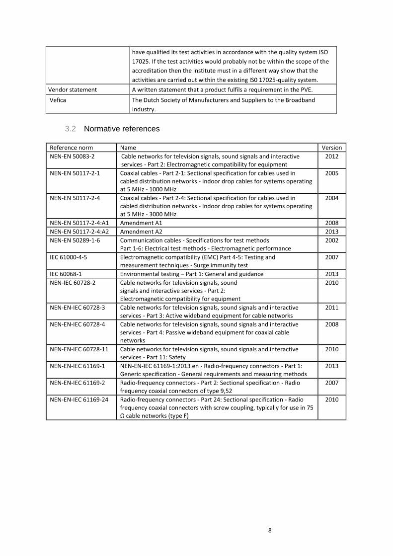
3.2 Normative references
Reference norm Name Version
NEN-EN 50083-2 Cable networks for television signals, sound signals and interactive services - Part 2: Electromagnetic compatibility for equipment
2012
NEN-EN 50117-2-1 Coaxial cables - Part 2-1: Sectional specification for cables used in cabled distribution networks - Indoor drop cables for systems operating at 5 MHz - 1000 MHz
2005
NEN-EN 50117-2-4
Coaxial cables - Part 2-4: Sectional specification for cables used in cabled distribution networks - Indoor drop cables for systems operating at 5 MHz - 3000 MHz
2004
NEN-EN 50117-2-4:A1 Amendment A1 2008
NEN-EN 50117-2-4:A2 Amendment A2 2013
NEN-EN 50289-1-6 Communication cables - Specifications for test methods Part 1-6: Electrical test methods - Electromagnetic performance
2002
IEC 61000-4-5 Electromagnetic compatibility (EMC) Part 4-5: Testing and measurement techniques - Surge immunity test
2007
IEC 60068-1 Environmental testing – Part 1: General and guidance 2013
NEN-IEC 60728-2 Cable networks for television signals, sound signals and interactive services - Part 2: Electromagnetic compatibility for equipment
2010
NEN-EN-IEC 60728-3 Cable networks for television signals, sound signals and interactive services - Part 3: Active wideband equipment for cable networks
2011
NEN-EN-IEC 60728-4 Cable networks for television signals, sound signals and interactive services - Part 4: Passive wideband equipment for coaxial cable networks
2008
NEN-EN-IEC 60728-11 Cable networks for television signals, sound signals and interactive services - Part 11: Safety
2010
NEN-EN-IEC 61169-1 NEN-EN-IEC 61169-1:2013 en - Radio-frequency connectors - Part 1: Generic specification - General requirements and measuring methods
2013
NEN-EN-IEC 61169-2 Radio-frequency connectors - Part 2: Sectional specification - Radio frequency coaxial connectors of type 9,52
2007
NEN-EN-IEC 61169-24 Radio-frequency connectors - Part 24: Sectional specification - Radio frequency coaxial connectors with screw coupling, typically for use in 75 Ω cable networks (type F)
2010

9
4 Procedure: Qualifying for Kabel Keur The flowchart in figure 1 shows the certification procedure for Kabel Keur. Certified kabel Keur products marketed under private labels need to be certified separately. Aspects that are not subject to difference from the originally certified product (original product), including technical specifications, may be excluded in the certification process for private label products.

10
Fig 1.

11
4.1 Requirements
This document describes the requirements products have to meet to qualify for the “Kabel Keur” certification
mark. The “Kabel Keur” certification mark is protected and registered by NLkabel. These requirements are
composed by a college of experts consisting of representatives of Dutch Cable Providers as well as leading
manufacturers.
4.2 Application
To apply for certification, requesting suppliers can obtain an application form from Keurmerkinstituut. Only
completed and signed forms will be considered. This includes the required attachments named on the application
form. By signing the form the requesting supplier declares to abide the rules and regulations for using the
certification “Kabel Keur” mark as stated in this PVE. After a completed entry form has been received,
Keurmerkinstituut will judge whether the products in the application are within the scope of the PVE. The NLkabel
members of the CVD will decide whether the products can be applied successfully in the Dutch cable operation
environment. The interoperability of products is a key decisive factor. If not, the certification procedure will be
stopped. Products omitted from the PVE are not covered.
4.3 Quote
After receipt of a completed and signed application form the Keurmerkinstituut shall offer a proposal for
examination and will charge the costs of application upfront. If the contract is granted, these application costs will
be deducted from the final bill.
4.4 Certification procedure
To be able to complete the certification procedure for original products, Keurmerkinstituut requires the following:
Product specification sheet
Representative product samples (see 6.5 for details)
Packaging samples, including any directions for use
Product marking (batch codes, product codes, logo’s, etc.)
CE-conformity declaration
Abstract Chamber of Commerce registration
Complaints procedure
Any other documents to show compliance with the requirements
For original products, Keurmerkinstituut also needs the following additional document:
An ISO 9001 certificate for the production process
For the purpose of the certification, a product includes any packaging, information and labeling as it is sold. If
factory-packaging is applicable the applier should indicate this.
Testing of compliance to technical requirements is reported to Keurmerkinstituut by a qualified laboratory. A
representative sample is tested in one of three ways.
Option 1 The applicant requests a qualified laboratory to test the product. The laboratory reports to Keurmerkinstituut and
all communication with the laboratory is through Keurmerkinstituut.
12
Option 2 Keurmerkinstituut boards testing of the product to a qualified laboratory. The laboratory reports to
Keurmerkinstituut and communication with the laboratory is through Keurmerkinstituut.
Option 3 The applicant arranges the product testing. Keurmerkinstituut has a qualified laboratory witness the testing and
this laboratory reports to Keurmerkinstituut.
Based on the laboratory report Keurmerkinstituut will evaluate validity of the tests and the compliance with
technical requirements. Keurmerkinstituut also evaluates the validity of the tested sample and the qualification of
the laboratory.
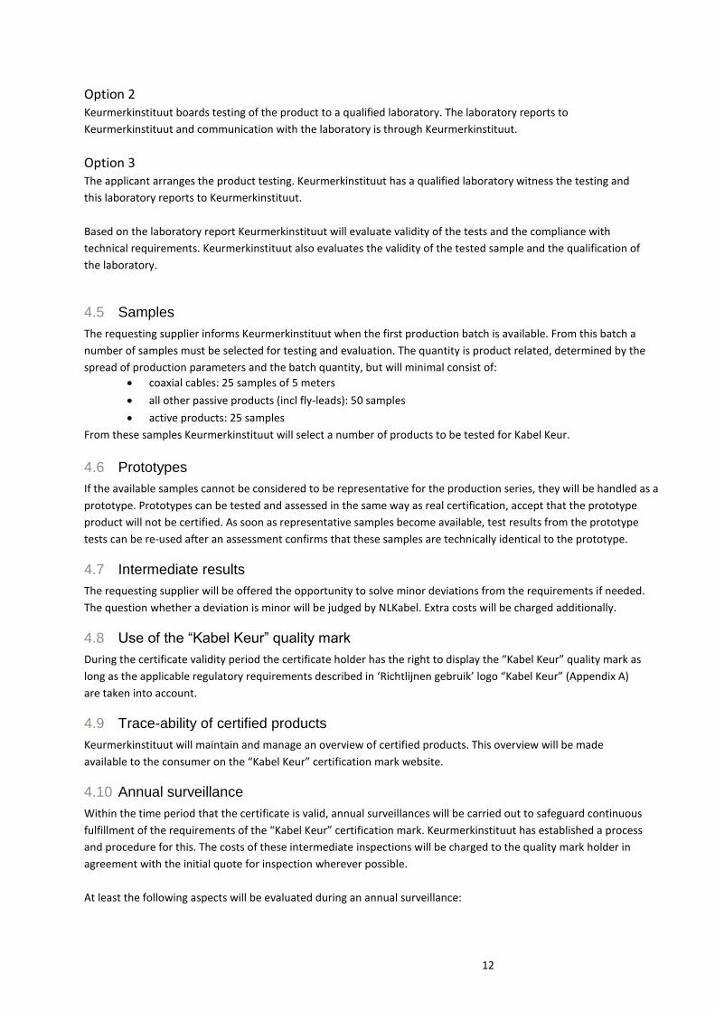
4.5 Samples
The requesting supplier informs Keurmerkinstituut when the first production batch is available. From this batch a
number of samples must be selected for testing and evaluation. The quantity is product related, determined by the
spread of production parameters and the batch quantity, but will minimal consist of:
coaxial cables: 25 samples of 5 meters
all other passive products (incl fly-leads): 50 samples
active products: 25 samples
From these samples Keurmerkinstituut will select a number of products to be tested for Kabel Keur.
4.6 Prototypes
If the available samples cannot be considered to be representative for the production series, they will be handled as a
prototype. Prototypes can be tested and assessed in the same way as real certification, accept that the prototype
product will not be certified. As soon as representative samples become available, test results from the prototype
tests can be re-used after an assessment confirms that these samples are technically identical to the prototype.
4.7 Intermediate results
The requesting supplier will be offered the opportunity to solve minor deviations from the requirements if needed.
The question whether a deviation is minor will be judged by NLKabel. Extra costs will be charged additionally.
4.8 Use of the “Kabel Keur” quality mark
During the certificate validity period the certificate holder has the right to display the “Kabel Keur” quality mark as
long as the applicable regulatory requirements described in ‘Richtlijnen gebruik’ logo “Kabel Keur” (Appendix A)
are taken into account.
4.9 Trace-ability of certified products
Keurmerkinstituut will maintain and manage an overview of certified products. This overview will be made
available to the consumer on the “Kabel Keur” certification mark website.
4.10 Annual surveillance
Within the time period that the certificate is valid, annual surveillances will be carried out to safeguard continuous
fulfillment of the requirements of the “Kabel Keur” certification mark. Keurmerkinstituut has established a process
and procedure for this. The costs of these intermediate inspections will be charged to the quality mark holder in
agreement with the initial quote for inspection wherever possible.
At least the following aspects will be evaluated during an annual surveillance:
13
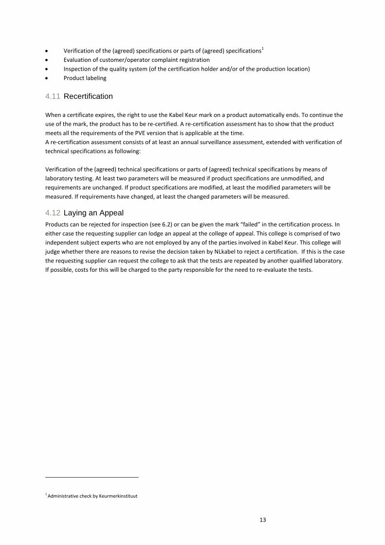
Verification of the (agreed) specifications or parts of (agreed) specifications1
Evaluation of customer/operator complaint registration
Inspection of the quality system (of the certification holder and/or of the production location)
Product labeling
4.11 Recertification
When a certificate expires, the right to use the Kabel Keur mark on a product automatically ends. To continue the
use of the mark, the product has to be re-certified. A re-certification assessment has to show that the product
meets all the requirements of the PVE version that is applicable at the time.
A re-certification assessment consists of at least an annual surveillance assessment, extended with verification of
technical specifications as following:
Verification of the (agreed) technical specifications or parts of (agreed) technical specifications by means of
laboratory testing. At least two parameters will be measured if product specifications are unmodified, and
requirements are unchanged. If product specifications are modified, at least the modified parameters will be
measured. If requirements have changed, at least the changed parameters will be measured.
4.12 Laying an Appeal
Products can be rejected for inspection (see 6.2) or can be given the mark “failed” in the certification process. In
either case the requesting supplier can lodge an appeal at the college of appeal. This college is comprised of two
independent subject experts who are not employed by any of the parties involved in Kabel Keur. This college will
judge whether there are reasons to revise the decision taken by NLkabel to reject a certification. If this is the case
the requesting supplier can request the college to ask that the tests are repeated by another qualified laboratory.
If possible, costs for this will be charged to the party responsible for the need to re-evaluate the tests.
1 Administrative check by Keurmerkinstituut
14
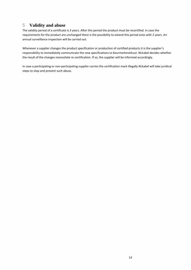
5 Validity and abuse The validity period of a certificate is 3 years. After this period the product must be recertified. In case the
requirements for the product are unchanged there is the possibility to extend this period ones with 2 years. An
annual surveillance inspection will be carried out.
Whenever a supplier changes the product specification or production of certified products it is the supplier’s
responsibility to immediately communicate the new specifications to Keurmerkinstituut. NLkabel decides whether
the result of the changes necessitate re-certification. If so, the supplier will be informed accordingly.
In case a participating or non-participating supplier carries the certification mark illegally NLkabel will take juridical
steps to stop and prevent such abuse.

15
6 Organisation NLkabel is assisted by a group of experts (“College van Deskundigen”, CVD). This CVD defines the
requirements for high performance components for In-house networks. These requirements are documented
in this document, called “Programma van Eisen”, abbreviated as PVE. The PVE document is public and, along
with other documents, published on NLkabel’s website via links to process partners who are responsible for
document distribution. New versions of the PVE documents also will be, as a standard process step,
distributed by mail to all participating partners in the “Kabel Keur” certification process. NLkabel has an
agreement with Keurmerkinstituut, in which is stated that Keurmerkinstituut will be responsible for all
operational activities. Keurmerkinstituut is in this context responsible for version control and distribution of all
process documentation and for all operational activities to enable requesting suppliers to obtain the
certification mark. All operational costs linked to obtaining the certification mark, such as the costs which
Keurmerkinstituut makes and the laboratory costs for the testing, are at the expense of the requesting
suppliers.
A requesting supplier who wants to acquire the certification mark for certain materials can submit a request
for this to Keurmerkinstituut. Materials can only be inspected if the requesting supplier agrees with the set of
rules and regulations that have been laid down by NLkabel in the PVE. This set of rules and regulations
indicates how the testing process is organized and what the general conditions are. Keurmerkinstituut boards
the testing to a qualified laboratory by default (see 4.4 for details).
The laboratory examines the material on behalf of Keurmerkinstituut according to the testing requirements
(PVE Active and Passive in-house materials) and reports the results to Keurmerkinstituut. Keurmerkinstituut
assesses the outcome and notifies to the requesting supplier on its findings. If the materials are approved then
Keurmerkinstituut, after being instructed to do so by NLkabel, will issue a certificate that allows the requesting
supplier to bear the certification mark for the examined material. On the certificate the type and validity
period of the inspected material is stated.
16
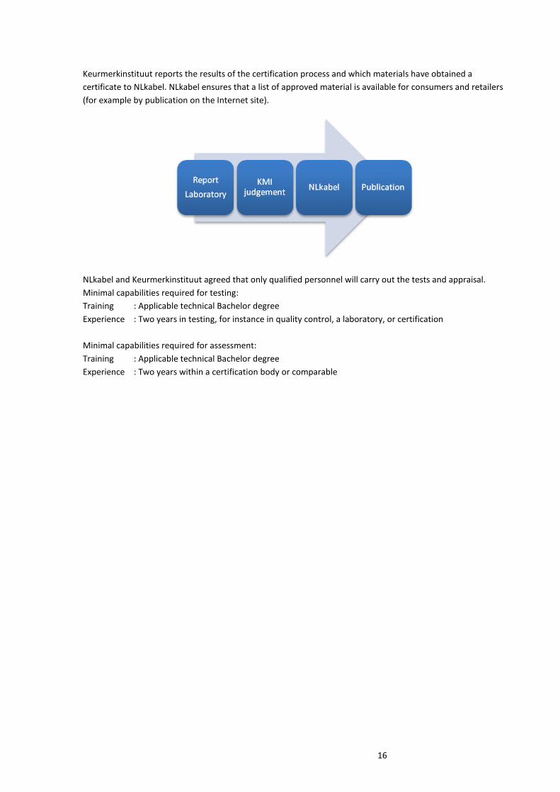
Keurmerkinstituut reports the results of the certification process and which materials have obtained a
certificate to NLkabel. NLkabel ensures that a list of approved material is available for consumers and retailers
(for example by publication on the Internet site).
NLkabel and Keurmerkinstituut agreed that only qualified personnel will carry out the tests and appraisal.
Minimal capabilities required for testing:
Training : Applicable technical Bachelor degree
Experience : Two years in testing, for instance in quality control, a laboratory, or certification
Minimal capabilities required for assessment:
Training : Applicable technical Bachelor degree
Experience : Two years within a certification body or comparable
17
7 Special products
Dutch Cable Operators prefer to certify all in home cable devices. This makes it easier for subscribers to
identify high quality approved products. Kabel Keur certified products are normally sold to the customer via a
retail shop for use in all Dutch Cable networks.
Special products are developed for a single Dutch Cable Operator or group of Dutch Cable Operators and are
not generally available via general retail stores. Distribution of these products takes place via installation kits
used by subscribers (“self install kits”) or via Dutch Cable Operator’s own retail shops.
Requirements for special products are normally not incorporated in this PVE. This is due to the competitor-
sensitivity of the specs. However the requirements of Kabel Keur products as specified in chapter 10 are
nonetheless also required for special products.
Special products must, apart from the Kabel Keur logo, contain a notification to which Dutch Cable operator
the product applies. Special products can also be common and be used by the majority of MSOs and, in this
case, the notification is not required.
At the request for certification of a Special Product to Keurmerkinstituut the requesting vendor will supply a
list of product requirements as specified by the Cable operator. On the basis of these requirements
Keurmerkinstituut will ask Telefication to test the product.
18
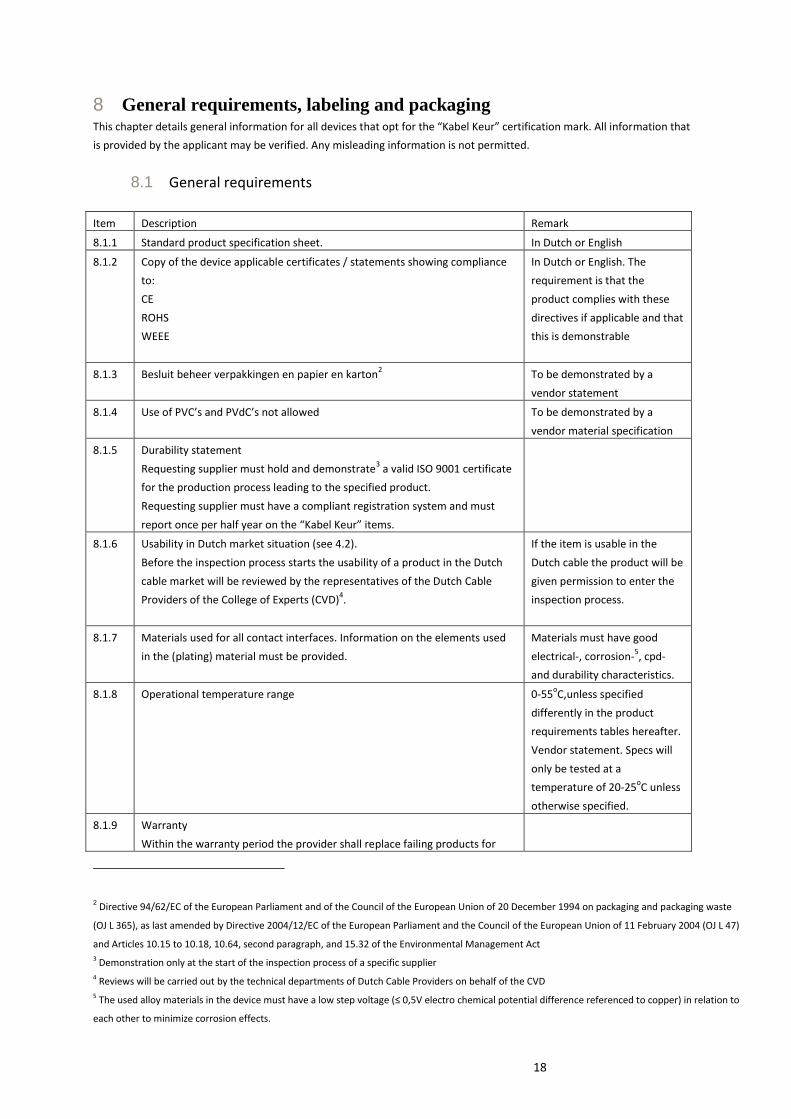
8 General requirements, labeling and packaging This chapter details general information for all devices that opt for the “Kabel Keur” certification mark. All information that
is provided by the applicant may be verified. Any misleading information is not permitted.
8.1 General requirements
Item Description Remark
8.1.1 Standard product specification sheet. In Dutch or English
8.1.2 Copy of the device applicable certificates / statements showing compliance
to:
CE
ROHS
WEEE
In Dutch or English. The
requirement is that the
product complies with these
directives if applicable and that
this is demonstrable
8.1.3 Besluit beheer verpakkingen en papier en karton2 To be demonstrated by a
vendor statement
8.1.4 Use of PVC’s and PVdC’s not allowed To be demonstrated by a
vendor material specification
8.1.5 Durability statement
Requesting supplier must hold and demonstrate3 a valid ISO 9001 certificate
for the production process leading to the specified product.
Requesting supplier must have a compliant registration system and must
report once per half year on the “Kabel Keur” items.
8.1.6 Usability in Dutch market situation (see 4.2).
Before the inspection process starts the usability of a product in the Dutch
cable market will be reviewed by the representatives of the Dutch Cable
Providers of the College of Experts (CVD)4.
If the item is usable in the
Dutch cable the product will be
given permission to enter the
inspection process.
8.1.7 Materials used for all contact interfaces. Information on the elements used
in the (plating) material must be provided.
Materials must have good
electrical-, corrosion-5, cpd-
and durability characteristics.
8.1.8 Operational temperature range 0-55oC,unless specified
differently in the product
requirements tables hereafter.
Vendor statement. Specs will
only be tested at a
temperature of 20-25oC unless
otherwise specified.
8.1.9 Warranty
Within the warranty period the provider shall replace failing products for
2 Directive 94/62/EC of the European Parliament and of the Council of the European Union of 20 December 1994 on packaging and packaging waste
(OJ L 365), as last amended by Directive 2004/12/EC of the European Parliament and the Council of the European Union of 11 February 2004 (OJ L 47)
and Articles 10.15 to 10.18, 10.64, second paragraph, and 15.32 of the Environmental Management Act 3 Demonstration only at the start of the inspection process of a specific supplier
4 Reviews will be carried out by the technical departments of Dutch Cable Providers on behalf of the CVD
5 The used alloy materials in the device must have a low step voltage (≤ 0,5V electro chemical potential difference referenced to copper) in relation to
each other to minimize corrosion effects.
19
free as long they are used in accordance with the instructions for use
provided. “Kabel Keur” products must have at least a 3-year warranty period.
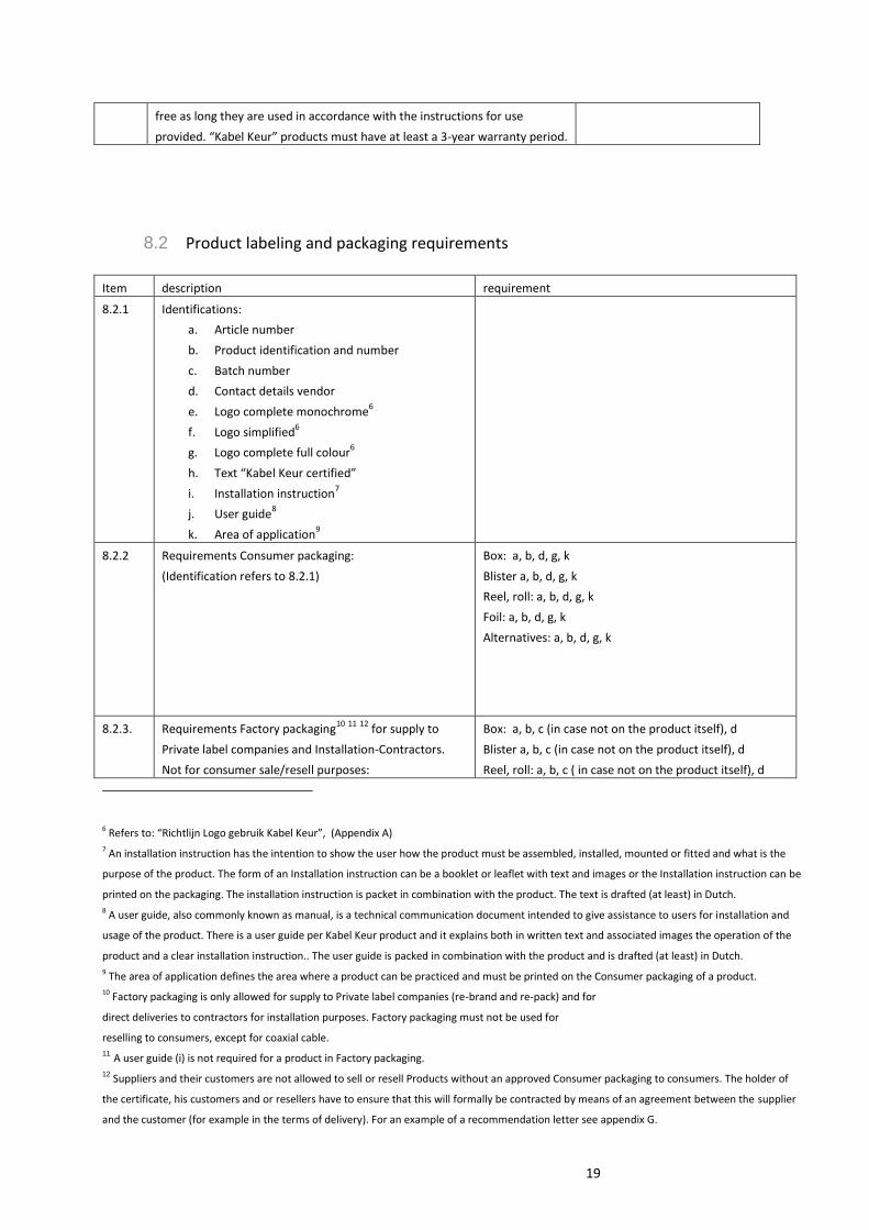
8.2 Product labeling and packaging requirements
Item description requirement
8.2.1 Identifications:
a. Article number
b. Product identification and number
c. Batch number
d. Contact details vendor
e. Logo complete monochrome6
f. Logo simplified6
g. Logo complete full colour6
h. Text “Kabel Keur certified”
i. Installation instruction7
j. User guide8
k. Area of application9
8.2.2 Requirements Consumer packaging:
(Identification refers to 8.2.1)
Box: a, b, d, g, k
Blister a, b, d, g, k
Reel, roll: a, b, d, g, k
Foil: a, b, d, g, k
Alternatives: a, b, d, g, k
8.2.3. Requirements Factory packaging10
11
12
for supply to
Private label companies and Installation-Contractors.
Not for consumer sale/resell purposes:
Box: a, b, c (in case not on the product itself), d
Blister a, b, c (in case not on the product itself), d
Reel, roll: a, b, c ( in case not on the product itself), d
6 Refers to: “Richtlijn Logo gebruik Kabel Keur”, (Appendix A) 7 An installation instruction has the intention to show the user how the product must be assembled, installed, mounted or fitted and what is the
purpose of the product. The form of an Installation instruction can be a booklet or leaflet with text and images or the Installation instruction can be
printed on the packaging. The installation instruction is packet in combination with the product. The text is drafted (at least) in Dutch. 8 A user guide, also commonly known as manual, is a technical communication document intended to give assistance to users for installation and
usage of the product. There is a user guide per Kabel Keur product and it explains both in written text and associated images the operation of the
product and a clear installation instruction.. The user guide is packed in combination with the product and is drafted (at least) in Dutch. 9 The area of application defines the area where a product can be practiced and must be printed on the Consumer packaging of a product. 10 Factory packaging is only allowed for supply to Private label companies (re-brand and re-pack) and for
direct deliveries to contractors for installation purposes. Factory packaging must not be used for
reselling to consumers, except for coaxial cable. 11 A user guide (i) is not required for a product in Factory packaging.
12 Suppliers and their customers are not allowed to sell or resell Products without an approved Consumer packaging to consumers. The holder of
the certificate, his customers and or resellers have to ensure that this will formally be contracted by means of an agreement between the supplier
and the customer (for example in the terms of delivery). For an example of a recommendation letter see appendix G.

20
(identification refers to 10.2.1)
Foil: a, b, c ( in case not on the product itself), d
Alternatives: a, b, c (in case not on the product itself), d
8.2.4 Requirements per product type
Wall Outlet
Two way splitter
Connector
Port terminator
Adaptor
Cable
Fly lead
Amplifier
HDMI cable
UTP cable
Diplex filter
Special product
b,c,f/g,i/j13
b,c,f/g,i
i
not applicable
not applicable
b, c13
, f/g/h
b, c13,
f/g/h
b, c, g, j
b, c, f/g/h
b, c, f/g/h
b, c, f/g, i
b, c, f/g, i/j
13 Batch number must be on the product or on the (factory) packaging of the product.
21
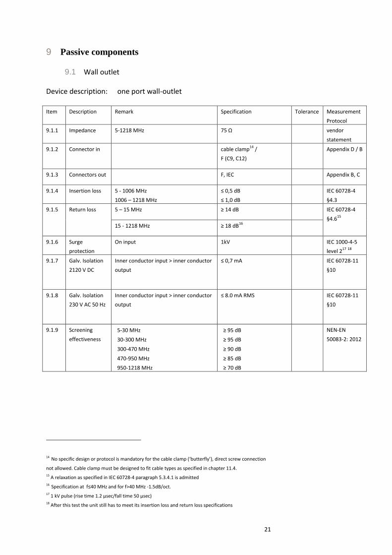
9 Passive components
9.1 Wall outlet Device description: one port wall-outlet
Item Description Remark Specification Tolerance Measurement
Protocol
9.1.1 Impedance 5-1218 MHz 75 Ω vendor
statement
9.1.2 Connector in cable clamp14
/
F (C9, C12)
Appendix D / B
9.1.3 Connectors out F, IEC Appendix B, C
9.1.4 Insertion loss 5 - 1006 MHz
1006 – 1218 MHz
≤ 0,5 dB
≤ 1,0 dB
IEC 60728-4
§4.3
9.1.5 Return loss 5 – 15 MHz ≥ 14 dB IEC 60728-4
§4.615
15 - 1218 MHz ≥ 18 dB
16
9.1.6 Surge
protection
On input 1kV IEC 1000-4-5
level 217
18
9.1.7 Galv. Isolation
2120 V DC
Inner conductor input > inner conductor
output
≤ 0,7 mA IEC 60728-11
§10
9.1.8 Galv. Isolation
230 V AC 50 Hz
Inner conductor input > inner conductor
output
≤ 8.0 mA RMS IEC 60728-11
§10
9.1.9 Screening
effectiveness
5-30 MHz
30-300 MHz
300-470 MHz
470-950 MHz
950-1218 MHz
≥ 95 dB
≥ 95 dB
≥ 90 dB
≥ 85 dB
≥ 70 dB
NEN-EN
50083-2: 2012
14 No specific design or protocol is mandatory for the cable clamp (‘butterfly’), direct screw connection
not allowed. Cable clamp must be designed to fit cable types as specified in chapter 11.4. 15 A relaxation as specified in IEC 60728-4 paragraph 5.3.4.1 is admitted 16 Specification at f≤40 MHz and for f>40 MHz -1.5dB/oct. 17 1 kV pulse (rise time 1.2 μsec/fall time 50 μsec) 18 After this test the unit still has to meet its insertion loss and return loss specifications

22
9.2 Two way Splitters Device description: two way splitter
item Description Remark Specification tolerance Measurement
Protocol
9.2.1 Impedance 5-1218 MHz 75 Ω
vendor statement
9.2.2 Connector in/out 19
F / IEC Appendix B, C
9.2.3 Insertion loss in >
out20
5 – 860 MHz ≤ 4,0 dB IEC 60728-4 §4.3
860 – 1006 MHz ≤ 4,3 dB
1006 - 1218 MHz ≤ 5.0 dB
9.2.4 Return loss 5 – 1218 MHz ≥ 18 dB21
IEC 60728-4 §4.6
9.2.5 Isolation out > out 5 – 15 MHz ≥ 20 dB
IEC 60728-4 §4.2
15 – 1218 MHz ≥ 26 dB21
9.2.6 Intermodulation -105 dBc
A minimum IMD of -105
dBc shall be measured
at the output(s) while
applying two carriers
(60 & 65 MHz), out to
out, @ 120 dBµV/60
dBmV, after 1kV
Combination Wave
(1,2µS rise time/50µS
duration) has been
applied at each port.
Test setup according to
IEC 60728-4 §4.8
9.2.7 Screening
effectiveness
5-30 MHz
30-300 MHz
300-470 MHz
470-950 MHz
950-1218 MHz
≥ 95 dB
≥ 95 dB
≥ 90 dB
≥ 85 dB
≥ 70 dB
NEN-EN 50083-2: 2012
19 Component may be equipped with either an IEC or F connector or a combination of both 20 A relaxation of 0,5 dB is allowed in case the two-splitter is equipped with special ingress- or high voltage protection features 21 Specification at f≤40 MHz and for f>40 MHz -1.5dB/oct.
23
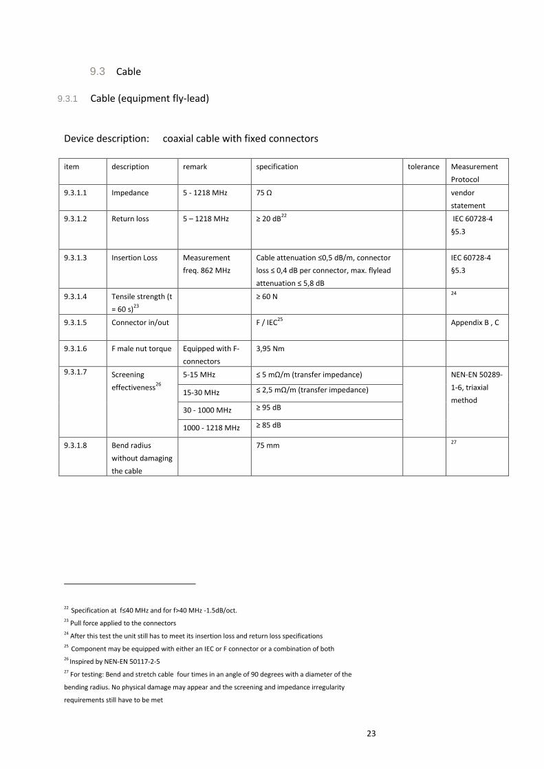
9.3 Cable
9.3.1 Cable (equipment fly-lead) Device description: coaxial cable with fixed connectors
item description remark specification tolerance Measurement
Protocol
9.3.1.1 Impedance 5 - 1218 MHz 75 Ω vendor
statement
9.3.1.2 Return loss 5 – 1218 MHz ≥ 20 dB22
IEC 60728-4
§5.3
9.3.1.3
Insertion Loss Measurement
freq. 862 MHz
Cable attenuation ≤0,5 dB/m, connector
loss ≤ 0,4 dB per connector, max. flylead
attenuation ≤ 5,8 dB
IEC 60728-4
§5.3
9.3.1.4 Tensile strength (t
= 60 s)23
≥ 60 N 24
9.3.1.5 Connector in/out F / IEC25
Appendix B , C
9.3.1.6 F male nut torque Equipped with F-
connectors
3,95 Nm
9.3.1.7 Screening
effectiveness26
5-15 MHz ≤ 5 mΩ/m (transfer impedance) NEN-EN 50289-
1-6, triaxial
method 15-30 MHz ≤ 2,5 mΩ/m (transfer impedance)
30 - 1000 MHz ≥ 95 dB
1000 - 1218 MHz ≥ 85 dB
9.3.1.8 Bend radius
without damaging
the cable
75 mm 27
22 Specification at f≤40 MHz and for f>40 MHz -1.5dB/oct. 23 Pull force applied to the connectors 24 After this test the unit still has to meet its insertion loss and return loss specifications 25 Component may be equipped with either an IEC or F connector or a combination of both 26 Inspired by NEN-EN 50117-2-5 27 For testing: Bend and stretch cable four times in an angle of 90 degrees with a diameter of the
bending radius. No physical damage may appear and the screening and impedance irregularity
requirements still have to be met
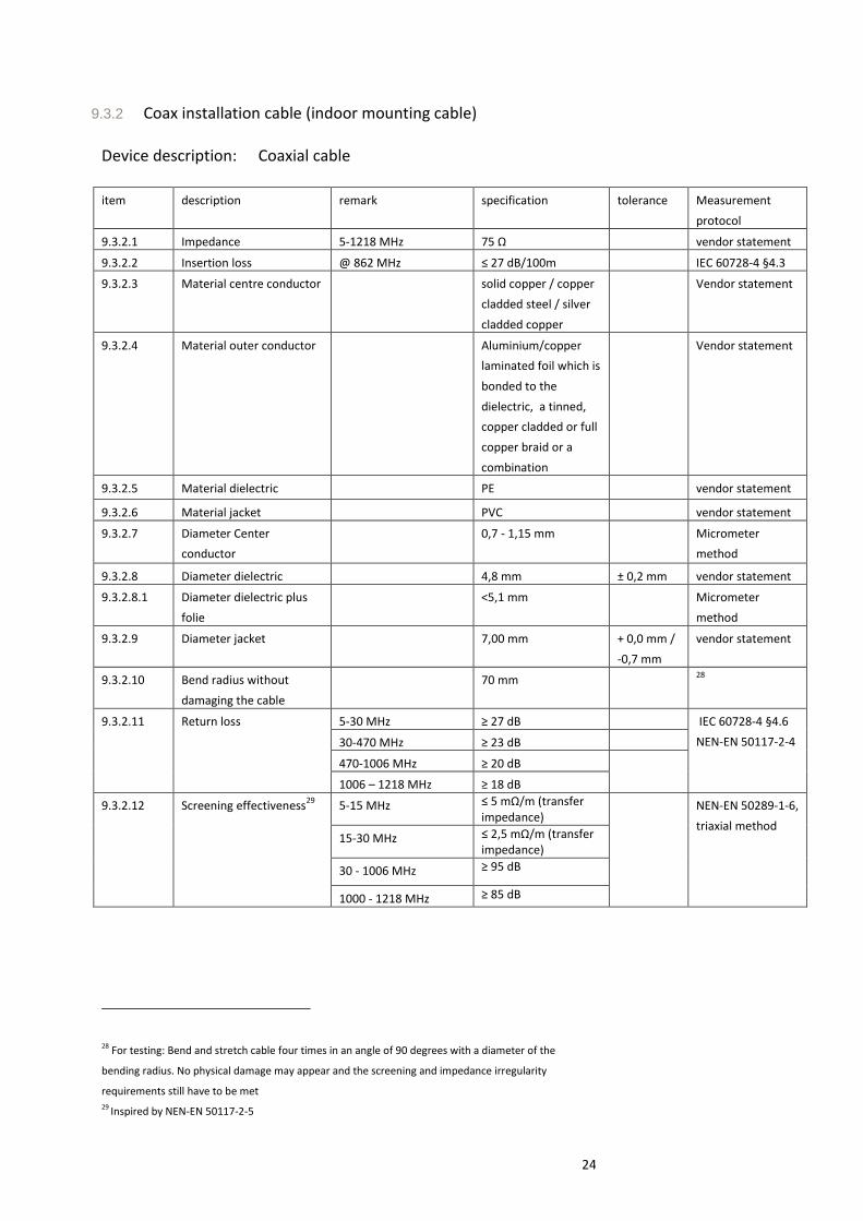
24
9.3.2 Coax installation cable (indoor mounting cable) Device description: Coaxial cable
item description remark specification tolerance Measurement
protocol
9.3.2.1 Impedance 5-1218 MHz 75 Ω vendor statement
9.3.2.2 Insertion loss @ 862 MHz ≤ 27 dB/100m IEC 60728-4 §4.3
9.3.2.3 Material centre conductor solid copper / copper
cladded steel / silver
cladded copper
Vendor statement
9.3.2.4 Material outer conductor Aluminium/copper
laminated foil which is
bonded to the
dielectric, a tinned,
copper cladded or full
copper braid or a
combination
Vendor statement
9.3.2.5 Material dielectric PE vendor statement
9.3.2.6 Material jacket PVC vendor statement
9.3.2.7 Diameter Center
conductor
0,7 - 1,15 mm Micrometer
method
9.3.2.8 Diameter dielectric 4,8 mm ± 0,2 mm vendor statement
9.3.2.8.1 Diameter dielectric plus
folie
<5,1 mm Micrometer
method
9.3.2.9 Diameter jacket 7,00 mm + 0,0 mm /
-0,7 mm
vendor statement
9.3.2.10 Bend radius without
damaging the cable
70 mm 28
9.3.2.11 Return loss 5-30 MHz ≥ 27 dB IEC 60728-4 §4.6
NEN-EN 50117-2-4 30-470 MHz ≥ 23 dB
470-1006 MHz ≥ 20 dB
1006 – 1218 MHz ≥ 18 dB
9.3.2.12 Screening effectiveness29
5-15 MHz ≤ 5 mΩ/m (transfer impedance)
NEN-EN 50289-1-6,
triaxial method 15-30 MHz ≤ 2,5 mΩ/m (transfer
impedance)
30 - 1006 MHz ≥ 95 dB
1000 - 1218 MHz ≥ 85 dB
28 For testing: Bend and stretch cable four times in an angle of 90 degrees with a diameter of the
bending radius. No physical damage may appear and the screening and impedance irregularity
requirements still have to be met 29 Inspired by NEN-EN 50117-2-5
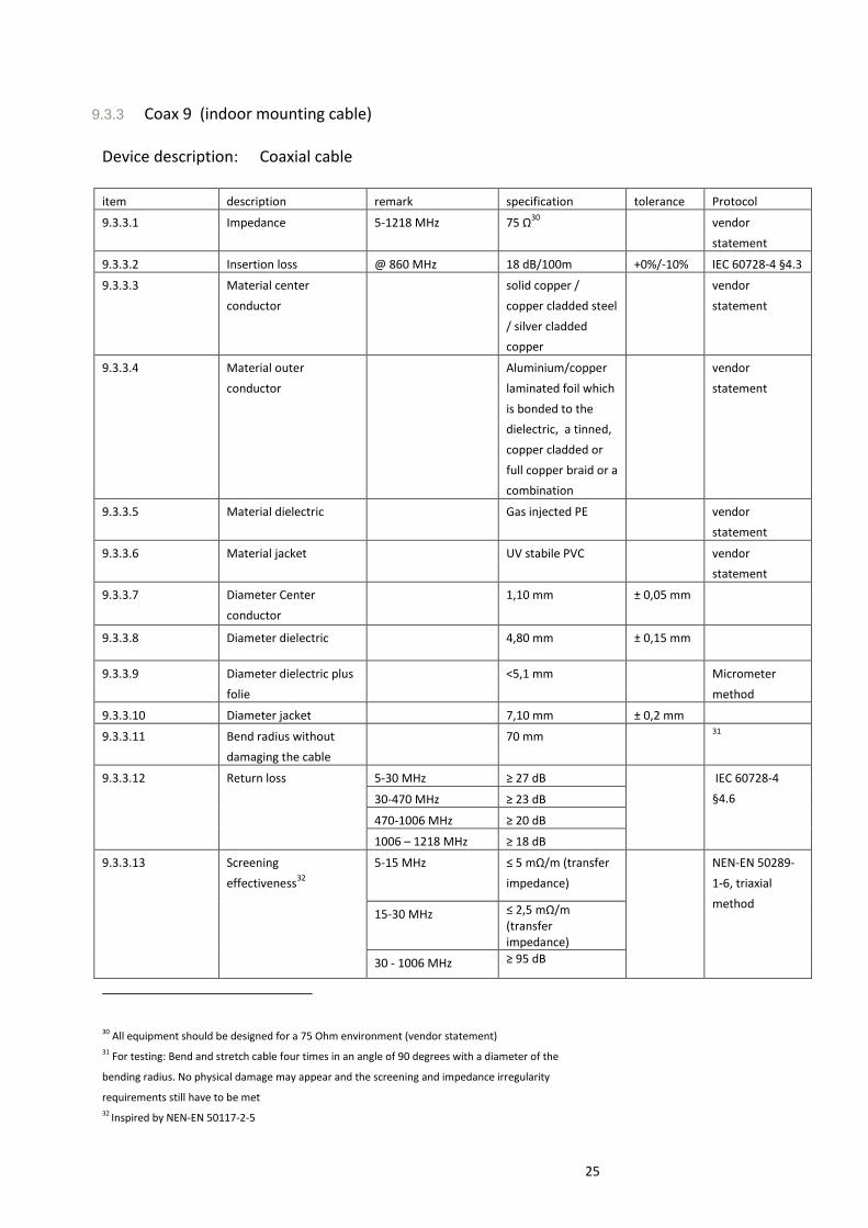
25
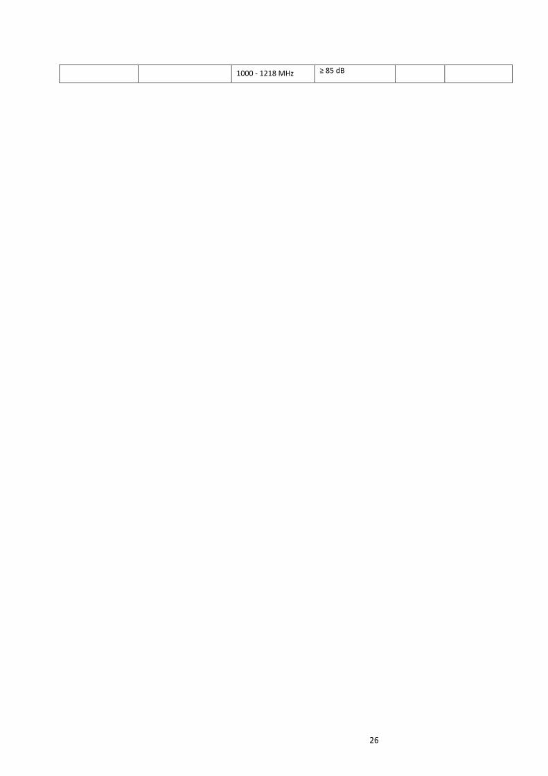
9.3.3 Coax 9 (indoor mounting cable) Device description: Coaxial cable
item description remark specification tolerance Protocol
9.3.3.1 Impedance 5-1218 MHz 75 Ω30
vendor
statement
9.3.3.2 Insertion loss @ 860 MHz 18 dB/100m +0%/-10% IEC 60728-4 §4.3
9.3.3.3 Material center
conductor
solid copper /
copper cladded steel
/ silver cladded
copper
vendor
statement
9.3.3.4 Material outer
conductor
Aluminium/copper
laminated foil which
is bonded to the
dielectric, a tinned,
copper cladded or
full copper braid or a
combination
vendor
statement
9.3.3.5 Material dielectric Gas injected PE vendor
statement
9.3.3.6 Material jacket UV stabile PVC vendor
statement
9.3.3.7 Diameter Center
conductor
1,10 mm ± 0,05 mm
9.3.3.8 Diameter dielectric 4,80 mm ± 0,15 mm
9.3.3.9 Diameter dielectric plus
folie
<5,1 mm Micrometer
method
9.3.3.10 Diameter jacket 7,10 mm ± 0,2 mm
9.3.3.11 Bend radius without
damaging the cable
70 mm 31
9.3.3.12 Return loss 5-30 MHz ≥ 27 dB
IEC 60728-4
§4.6 30-470 MHz ≥ 23 dB
470-1006 MHz ≥ 20 dB
1006 – 1218 MHz ≥ 18 dB
9.3.3.13 Screening
effectiveness32
5-15 MHz ≤ 5 mΩ/m (transfer
impedance)
NEN-EN 50289-
1-6, triaxial
method 15-30 MHz ≤ 2,5 mΩ/m
(transfer impedance)
30 - 1006 MHz ≥ 95 dB
30 All equipment should be designed for a 75 Ohm environment (vendor statement) 31 For testing: Bend and stretch cable four times in an angle of 90 degrees with a diameter of the
bending radius. No physical damage may appear and the screening and impedance irregularity
requirements still have to be met 32 Inspired by NEN-EN 50117-2-5
26
1000 - 1218 MHz ≥ 85 dB
27
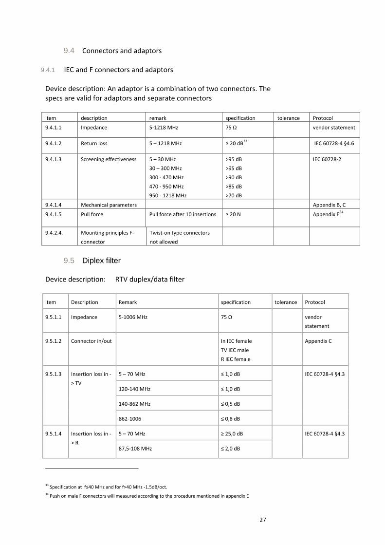
9.4 Connectors and adaptors
9.4.1 IEC and F connectors and adaptors Device description: An adaptor is a combination of two connectors. The specs are valid for adaptors and separate connectors
item description remark specification tolerance Protocol
9.4.1.1 Impedance 5-1218 MHz 75 Ω vendor statement
9.4.1.2 Return loss 5 – 1218 MHz ≥ 20 dB33
IEC 60728-4 §4.6
9.4.1.3 Screening effectiveness 5 – 30 MHz
30 – 300 MHz
300 - 470 MHz
470 - 950 MHz
950 - 1218 MHz
>95 dB
>95 dB
>90 dB
>85 dB
>70 dB
IEC 60728-2
9.4.1.4 Mechanical parameters Appendix B, C
9.4.1.5 Pull force Pull force after 10 insertions ≥ 20 N Appendix E34
9.4.2.4. Mounting principles F-
connector
Twist-on type connectors
not allowed
9.5 Diplex filter Device description: RTV duplex/data filter
item Description Remark specification tolerance Protocol
9.5.1.1 Impedance 5-1006 MHz 75 Ω vendor
statement
9.5.1.2 Connector in/out In IEC female
TV IEC male
R IEC female
Appendix C
9.5.1.3
Insertion loss in -
> TV
5 – 70 MHz ≤ 1,0 dB
IEC 60728-4 §4.3
120-140 MHz ≤ 1,0 dB
140-862 MHz ≤ 0,5 dB
862-1006 ≤ 0,8 dB
9.5.1.4
Insertion loss in -
> R
5 – 70 MHz ≥ 25,0 dB
IEC 60728-4 §4.3
87,5-108 MHz ≤ 2,0 dB
33 Specification at f≤40 MHz and for f>40 MHz -1.5dB/oct. 34 Push on male F connectors will measured according to the procedure mentioned in appendix E

28
9.5.1.5 Return loss TV 5- 70 MHz
120 – 1006 MHz
≥14 dB
≥14 dB
IEC 60728-4
§4.6
9.5.1.6 Return loss R 87,5-108 MHz ≥10 dB IEC 60728-4 §4.6
9.5.1.7.
Return loss In
5-70 MHz ≥14 dB
IEC 60728-4 §4.6
87,5-108 MHz ≥10 dB
120-1006 MHz ≥14 dB
9.5.1.8
Isolation TV-R
5 – 70 MHz ≥ 25 dB
IEC 60728-4 §4.2
87,5-108 MHz ≥16 dB
120 – 1006 MHz ≥ 25 dB
9.5.1.9 Screening
effectiveness
5-30 MHz
30-300 MHz
300-470 MHz
470-950 MHz
950-1006 MHz
≥ 95 dB
≥ 95 dB
≥ 90 dB
≥ 85 dB
≥ 70 dB
NEN-EN 50083-
2:2012
9.6 Port terminator Device description: Termination resistor
Item Description Remark Specification Tolerance Protocol
9.6.1.1 Impedance 5 - 1218 MHz 75 Ω vendor statement
9.6.1.2 Frequency range 5 - 1218 MHz
9.6.1.3 Return loss 5 – 1218 MHz ≥ 20 dB35
IEC 60728-4 §4.6
9.6.1.4 Torque (rotation) F
(if applicable)
≥5 Nm
9.6.1.5 Connector F/IEC-connector Appendix B, C
9.6.1.6 Screening effectiveness 5-30 MHz
30-300 MHz
300-470 MHz
470-950 MHz
950-1218 MHz
≥ 95 dB
≥ 95 dB
≥ 90 dB
≥ 85 dB
≥ 70 dB
NEN-EN 50083-2:2012
35 Specification at f≤40 MHz and for f>40 MHz -1.5dB/oct.

29
9.7 HDMI cable Device description: HDMI (High-Definition Multimedia Interface) is a compact
audio/video interface for transmitting uncompressed digital data. HDMI supports, on a single cable, any TV or PC video format, including standard, enhanced, and high-definition video, up to 8 channels of digital audio, and the Consumer Electronics Control signal.
item description Remark specification tolerance Protocol
9.7.1 Construction
Fully shielded cable. Molded ends.
Inner hood connected 360 degrees
to the connector for complete end
shielding.
HDMI Specification High
Speed (category 2 or
higher)
9.7.2 Interface HDMI-A Interface[1] HDMI Specification High
Speed (category 2 or
higher)
9.7.3 Ferrite Both sides of the
cable should
contain a ferrite
to prevent
unwanted e-gress
and ingress
(shortcut shielding
currents 0-1GHz).
Ferrite specification
Impedance ≥200 Ohm @ 1 GHz
See Appendix F
9.7.4 Marking “Kabel Keur certified” and HDMI
label must be printed on the cable
(label) or the connector36
9.7.5 HDMI
approved
The vendor must provide a
certificate of HDMI ATC compliance
and an ATC testing result
36 Label format corresponding to www.hdmi.org.
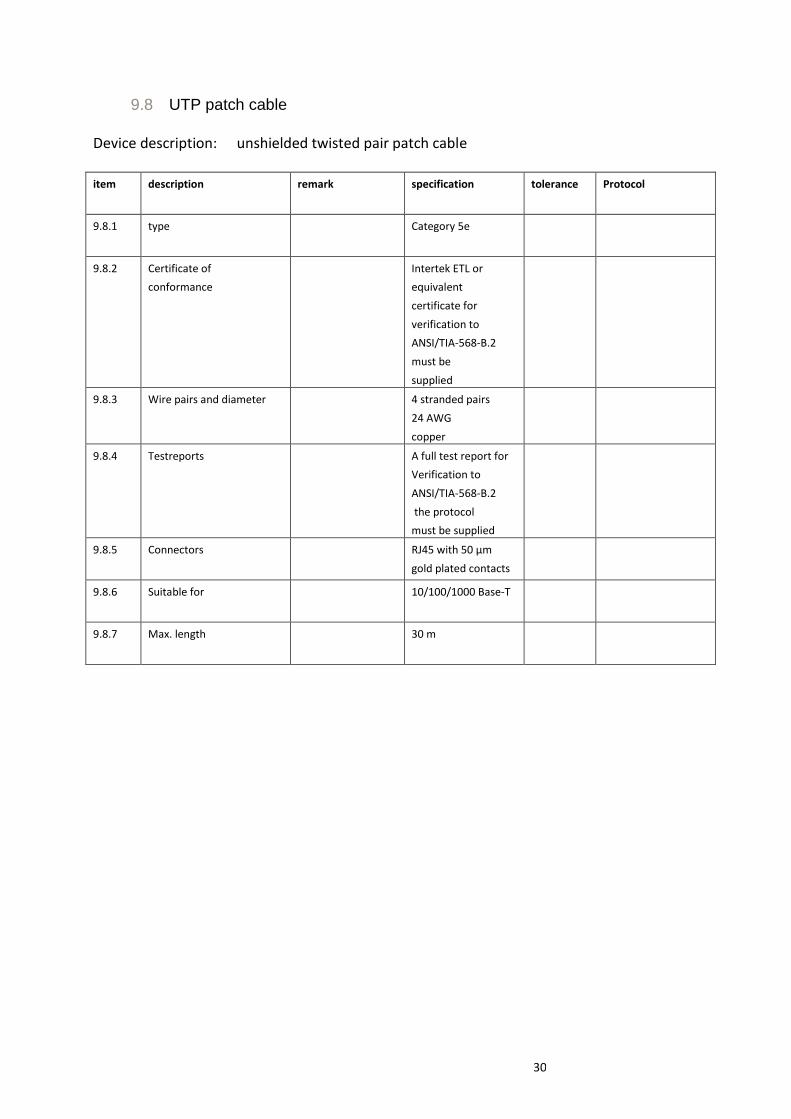
30
9.8 UTP patch cable Device description: unshielded twisted pair patch cable
item description remark specification tolerance Protocol
9.8.1 type Category 5e
9.8.2 Certificate of
conformance
Intertek ETL or
equivalent
certificate for
verification to
ANSI/TIA-568-B.2
must be
supplied
9.8.3 Wire pairs and diameter 4 stranded pairs
24 AWG
copper
9.8.4 Testreports A full test report for
Verification to
ANSI/TIA-568-B.2
the protocol
must be supplied
9.8.5 Connectors RJ45 with 50 µm
gold plated contacts
9.8.6 Suitable for 10/100/1000 Base-T
9.8.7 Max. length 30 m

31
10 Active components
10.1 Amplifier Device description: Amplifier (862 MHz) with one or multiple outputs, either wall mounted or push-on, (n-1) outputs must have a 75 ohm termination.
item description remark specification tolerance Protocol
10.1.1 Gain forward path (port – port) range 85 - 862 MHz 1 – 9 dB37
± 1,5 dB38
IEC60728-3 §5.6
10.1.2 Cable compensating slope 85 - 862 MHz ≤ 1,5 dB see
figure after this
table
10.1.3 Gain return path (port – port) range
- Forward gain ≥7 dB
- Forward gain <7 dB
- Gain ripple/error
5 - 65 MHz
0 - 5 dB
0 - 2 dB
± 1,0 dB
IEC60728-3 §5.6
10.1.4 Connectors in- out F, IEC Appendix B, C
10.1.5 Isolation RF-IN to Outputs 5 - 65 MHz ≥ 26 dB IEC 60728-4 §4.2
Outputs to RF-IN 85 - 862 MHz ≥ 26 dB
Outputs to Outputs 5 – 15 MHz ≥ 20 dB
Outputs to Outputs 15 - 65 MHz ≥ 30 dB
Outputs to Outputs 85 - 862 MHz ≥ 26 dB
10.1.6 Return loss input39
5 – 65 MHz ≥ 18 dB IEC60728-3 &5.5
85 – 862 MHz ≥ 18 dB
10.1.7 Return loss output 40
5 – 65 MHz ≥ 18 dB
85 – 862 MHz ≥ 18 dB
10.1.8 Noise figure 5-65 MHz ≤ 18 dB IEC 60728-3 §4.4
85-120 MHz ≤ 9 dB
120-862 MHz ≤ 8 dB
10.1.9 Nominal input level (PAL)41
≤ 77 dBuV
10.1.10 Forward path
distortion
CSO. @ (77+gain) dBuV output < - 64 dBc42
IEC 60728-3
§4.2.3
37 Unit may have either equal gain outputs or stepped gain outputs. Low gain amplifiers have preferable no adjustable gain. 38 Gain forward path tolerance including temperature variation and gain ripple are indicated in the figures on page 31. 39 Specification at f≤40 MHz and for f>40 MHz -1.5dB/oct with a minimum of 10 dB. Specification at f<40 MHz and -1,5/oct (f>40MHz) 40 Specification at f≤40 MHz and for f>40 MHz -1.5dB/oct with a minimum of 10 dB. Specification at f<40 MHz and -1,5/oct (f>40MHz) 41 Input channel load consists of 42 FM Channels, between 30-50 analogue (PAL) channels and 30-50 digital (QAM) signals 42 Measured at output level (output level = input level + gain)
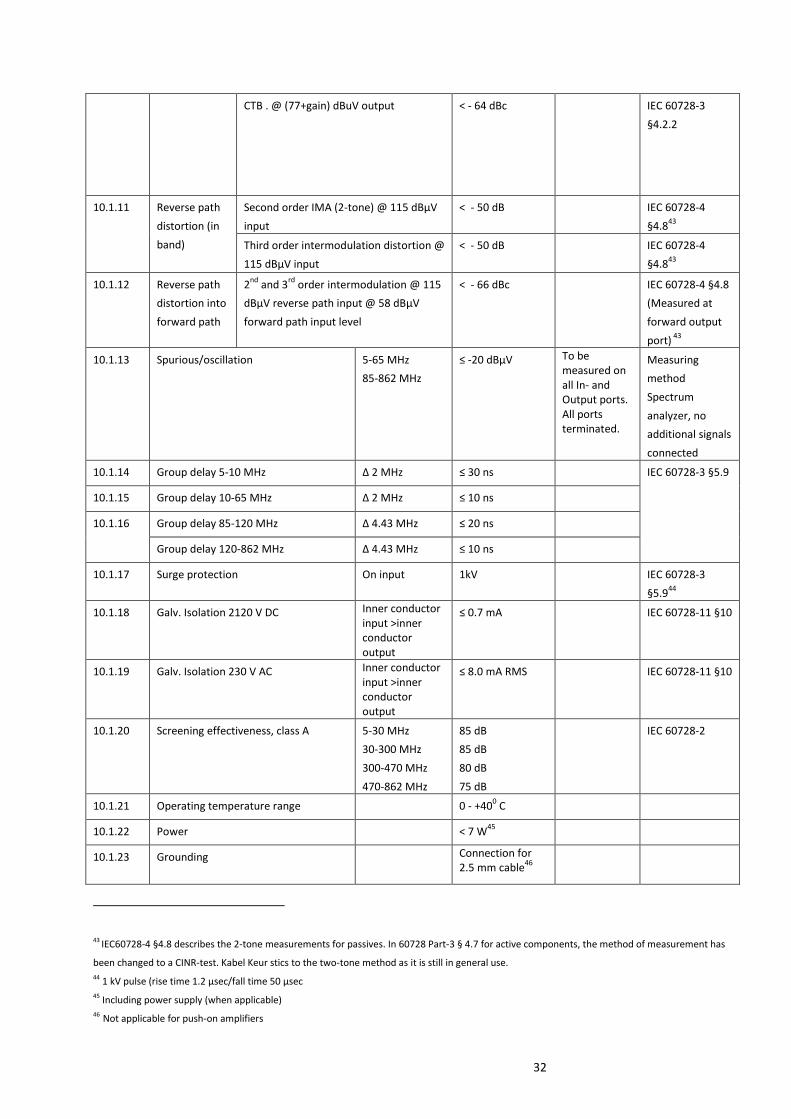
32
CTB . @ (77+gain) dBuV output < - 64 dBc IEC 60728-3
§4.2.2
10.1.11 Reverse path
distortion (in
band)
Second order IMA (2-tone) @ 115 dBμV
input
< - 50 dB IEC 60728-4
§4.843
Third order intermodulation distortion @
115 dBμV input
< - 50 dB IEC 60728-4
§4.843
10.1.12 Reverse path
distortion into
forward path
2nd
and 3rd
order intermodulation @ 115
dBμV reverse path input @ 58 dBμV
forward path input level
< - 66 dBc
IEC 60728-4 §4.8
(Measured at
forward output
port) 43
10.1.13 Spurious/oscillation 5-65 MHz
85-862 MHz
≤ -20 dBμV
To be measured on all In- and Output ports. All ports terminated.
Measuring
method
Spectrum
analyzer, no
additional signals
connected
10.1.14 Group delay 5-10 MHz ∆ 2 MHz ≤ 30 ns IEC 60728-3 §5.9
10.1.15 Group delay 10-65 MHz ∆ 2 MHz ≤ 10 ns
10.1.16 Group delay 85-120 MHz Δ 4.43 MHz ≤ 20 ns
Group delay 120-862 MHz Δ 4.43 MHz ≤ 10 ns
10.1.17 Surge protection On input 1kV IEC 60728-3
§5.944
10.1.18 Galv. Isolation 2120 V DC Inner conductor input >inner conductor output
≤ 0.7 mA IEC 60728-11 §10
10.1.19 Galv. Isolation 230 V AC Inner conductor input >inner conductor output
≤ 8.0 mA RMS IEC 60728-11 §10
10.1.20 Screening effectiveness, class A 5-30 MHz
30-300 MHz
300-470 MHz
470-862 MHz
85 dB
85 dB
80 dB
75 dB
IEC 60728-2
10.1.21 Operating temperature range 0 - +400 C
10.1.22 Power < 7 W45
10.1.23 Grounding Connection for 2.5 mm cable
46
43 IEC60728-4 §4.8 describes the 2-tone measurements for passives. In 60728 Part-3 § 4.7 for active components, the method of measurement has
been changed to a CINR-test. Kabel Keur stics to the two-tone method as it is still in general use. 44 1 kV pulse (rise time 1.2 μsec/fall time 50 μsec 45 Including power supply (when applicable) 46 Not applicable for push-on amplifiers
33
10.1.24 Port termination n-1 output must
have a 75 ohm
termination
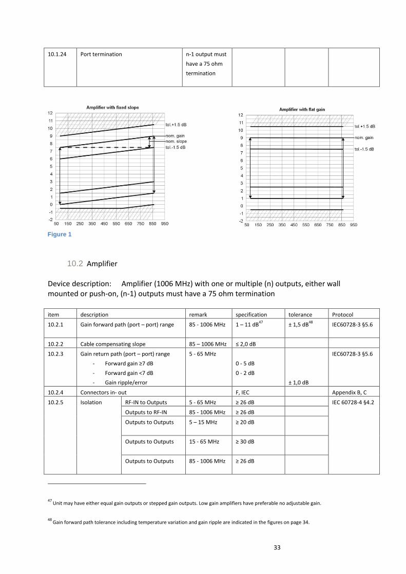
10.2 Amplifier
Device description: Amplifier (1006 MHz) with one or multiple (n) outputs, either wall mounted or push-on, (n-1) outputs must have a 75 ohm termination
item description remark specification tolerance Protocol
10.2.1 Gain forward path (port – port) range 85 - 1006 MHz 1 – 11 dB47
± 1,5 dB48
IEC60728-3 §5.6
10.2.2 Cable compensating slope 85 – 1006 MHz ≤ 2,0 dB
10.2.3 Gain return path (port – port) range
- Forward gain ≥7 dB
- Forward gain <7 dB
- Gain ripple/error
5 - 65 MHz
0 - 5 dB
0 - 2 dB
± 1,0 dB
IEC60728-3 §5.6
10.2.4 Connectors in- out F, IEC Appendix B, C
10.2.5 Isolation RF-IN to Outputs 5 - 65 MHz ≥ 26 dB IEC 60728-4 §4.2
Outputs to RF-IN 85 - 1006 MHz ≥ 26 dB
Outputs to Outputs 5 – 15 MHz ≥ 20 dB
Outputs to Outputs 15 - 65 MHz ≥ 30 dB
Outputs to Outputs 85 - 1006 MHz ≥ 26 dB
47
Unit may have either equal gain outputs or stepped gain outputs. Low gain amplifiers have preferable no adjustable gain. 48
Gain forward path tolerance including temperature variation and gain ripple are indicated in the figures on page 34.
Figure 1

34
10.2.6 Return loss input49
5 – 65 MHz ≥ 18 dB IEC60728-3 &5.5
85 – 1006 MHz ≥ 18 dB
10.2.7 Return loss output50
5 – 65 MHz ≥ 18 dB
85 – 1006 MHz ≥ 18 dB
10.2.8 Noise figure 5-65 MHz ≤ 18 dB IEC 60728-3 §4.4
85-120 MHz ≤ 9 dB
120-1006 MHz ≤ 8 dB
10.2.9 Nominal input level (PAL)51
≤ 77 dBuV
10.2.10 Forward path
distortion
CSO @ (77+gain) dBuV output < - 65 dBc52
IEC 60728-3
§4.2.3
CTB @ (77+gain) dBuV output < - 66 dBc
IEC 60728-3
§4.2.2
10.2.11 Reverse path
distortion (in
band)
Second order IMA (2-tone) @ 115 dBμV
input
< - 50 dB
IEC 60728-4
§4.853
Third order intermodulation distortion @
115 dBμV input
< - 50 dB
IEC 60728-4
§4.853
10.2.12 Reverse path
distortion into
forward path
2nd
and 3rd
order intermodulation @ 115
dBμV reverse path input @ 58 dBμV
forward path input level
< - 66 dBc
IEC 60728-4
§4.853
(measured at
forward output
port)
10.2.13 Spurious/oscil
lation
5-65 MHz
85-1006 MHz
≤ -20 dBμV
To be measured on all In- Output ports. All ports terminated.
Measuring
method
Spectrum
analyzer, no
additional signals
connected
10.2.14 Group delay
5-10 MHz
∆ 2 MHz ≤ 30 ns IEC 60728-3 §5.9
10.2.15 Group delay
10-65 MHz
∆ 2 MHz ≤ 10 ns
10.2.16 Group delay
85-120 MHz
Δ 4.43 MHz ≤ 20 ns
Group delay
120-1006
MHz
Δ 4.43 MHz ≤ 10 ns
49 Specification at f≤40 MHz and for f>40 MHz -1.5dB/oct with a minimum of 10 dB. Specification at f<40 MHz and -1,5/oct (f>40MHz) 50
Specification at f≤40 MHz and for f>40 MHz -1.5dB/oct with a minimum of 10 dB. Specification at f<40 MHz and -1,5/oct (f>40MHz) 51
Input channel load consists of 42 FM Channels, between 30-50 analogue (PAL) channels and 30-50 digital (QAM) signals 52
Measured at output level (output level = input level + gain) 53
IEC60728-4 §4.8 describes the 2-tone measurements for passives. In 60728 Part-3 § 4.7 for active components, the method of measurement has
been changed to a CINR-test. Kabel Keur sticks to the two-tone method as it is still in general use.

35
10.2.17 Surge
protection
On input 1kV IEC 60728-3
§5.954
10.2.18 Galv. Isolation
2120 V DC
Inner conductor input >inner conductor output
≤ 0.7 mA IEC 60728-11 §10
10.2.19 Galv. Isolation
230 V AC
Inner conductor input >inner conductor output
≤ 8.0 mA RMS IEC 60728-11 §10
10.2.20 Screening effectiveness, class A 5-30 MHz
30-300 MHz
300-470 MHz
470-1006 MHz
85 dB
85 dB
80 dB
75 dB
IEC 60728-2
10.2.21 Operating temperature range 0 - +400 C
10.2.22 Power < 7 W55
10.2.23 Grounding Connection for 2.5 mm cable
10.2.24 Port termination n-1 output must
have a 75 ohm
termination
Figure 2
54 1 kV pulse (rise time 1.2 μsec/fall time 50 μsec 55 Not applicable for push-on amplifiers
36
11 Special products Vendor confidential
Procedure: see chapter 7

37
12 Appendix A: Logo’s Note: For product labeling see article 8.2
The Kabel Keur logo uses the following colors:
Blue: pms 2935 Green: pms 375
Logo Complete Full Color, the original Kabel Keur logo, has a minimum width of 10 mm.
Logo Complete Monochrome. This logo offers the possibility to display a grayscale picture in newspapers.
Logo Simplified should only be used in cases where the original logo cannot be placed on the product due to
minimal format requirements. The Logo Simplified is only allowed on products and not on packaging. The Logo
Simplified has a minimum width of 5 mm .

38
The Kabel Keur logo can be used together with a theme. In this case the minimum dimension is 30 mm for the
logo.
The theme should be minimum corps 8 (centered). The theme line must never be smaller than the width of the
logo.
The Kabel Keur logo must always be placed on white background..
The Kabel Keur logo can also be placed deep. Mind: Strainer print for packaging materials on a dark or
transparent background.
High resultion Logo files will at request be provided by NLkabel
Address:
Lange Voorhout 90 2514 EJ Den Haag Telefoon: 070 - 305 33 33
’t Beste beeld heeft Kabel Keur
39
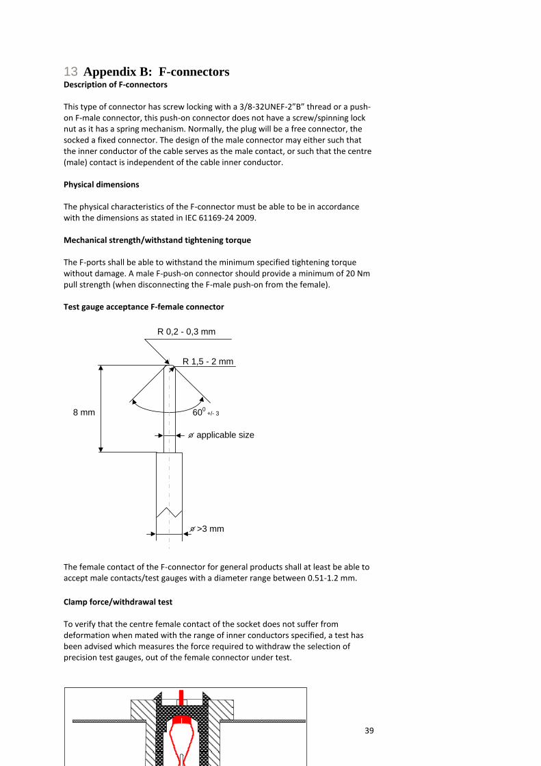
13 Appendix B: F-connectors Description of F-connectors This type of connector has screw locking with a 3/8-32UNEF-2”B” thread or a push-on F-male connector, this push-on connector does not have a screw/spinning lock nut as it has a spring mechanism. Normally, the plug will be a free connector, the socked a fixed connector. The design of the male connector may either such that the inner conductor of the cable serves as the male contact, or such that the centre (male) contact is independent of the cable inner conductor. Physical dimensions The physical characteristics of the F-connector must be able to be in accordance with the dimensions as stated in IEC 61169-24 2009. Mechanical strength/withstand tightening torque The F-ports shall be able to withstand the minimum specified tightening torque without damage. A male F-push-on connector should provide a minimum of 20 Nm pull strength (when disconnecting the F-male push-on from the female). Test gauge acceptance F-female connector
R 0,2 - 0,3 mm
8 mm
>3 mm
600
+/- 3
R 1,5 - 2 mm
applicable size
The female contact of the F-connector for general products shall at least be able to accept male contacts/test gauges with a diameter range between 0.51-1.2 mm.
Clamp force/withdrawal test To verify that the centre female contact of the socket does not suffer from deformation when mated with the range of inner conductors specified, a test has been advised which measures the force required to withdraw the selection of precision test gauges, out of the female connector under test.
40
Figure: Example of Clamp force test set up
General Products
Test sequence 1 2 3 4 5
Test gauge diameter (mm) 0.51 1.2 0.51 1.2 0.51
Clamping force min. (gram) 30 30
Clamping force tests must be performed with a duration of 10 seconds and at room temperature
Test gauge tolerance: +/- 0.01 mm
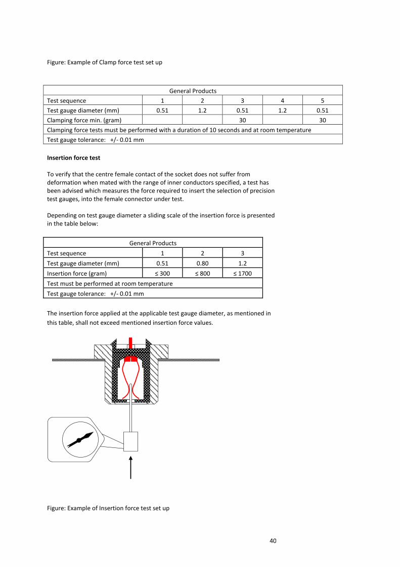
Insertion force test To verify that the centre female contact of the socket does not suffer from deformation when mated with the range of inner conductors specified, a test has been advised which measures the force required to insert the selection of precision test gauges, into the female connector under test. Depending on test gauge diameter a sliding scale of the insertion force is presented in the table below:
General Products
Test sequence 1 2 3
Test gauge diameter (mm) 0.51 0.80 1.2
Insertion force (gram) ≤ 300 ≤ 800 ≤ 1700
Test must be performed at room temperature
Test gauge tolerance: +/- 0.01 mm
The insertion force applied at the applicable test gauge diameter, as mentioned in
this table, shall not exceed mentioned insertion force values.
Figure: Example of Insertion force test set up

41

42
14 Appendix C: IEC-connectors Description of IEC type connectors (type 9,52) This type of connector has a push pull fitting without locking. Normally, the plug will be a free connector, the socked a fixed connector. The design of the plug may be such that the inner pin conductor serving as the male contact. Physical dimensions The physical characteristics of the IEC-connectors should be able to be in accordance with the dimensions as stated in IEC 61169-2, 2007. For moulded IEC-connectors there are following relaxations to the dimensions as stated in IEC-61169-2:
- For size “C” there is a relaxation from 8.5 mm min. to 7.9 mm min. due to tooling
angle.
- For size “D” there is a relaxation from 9.525 ± 0.05 mm (9.520 to 9.530 mm) to
9.45 - 9.57 mm (no tolerance).

43
IEC acceptance tests To verify the acceptable quality level the following test to ascertain the resilience of the conductor to insertion and withdrawal of a selection of precision test pins, into and out of the connector under test.
The tests are to determine:
A. Resilience of inner-pin
B. Resilience of outer-conductor
C. Torque resistance of inner-pin A. The test gauge dimensions for “resilience of inner-pin” are shown as follows:
Dimensions (mm)
Tolerance
Test gauge A Ø 2.438 0, -0.01
Test gauge B Ø 2.286 +0.01, 0
Weight of test gauge B should be 30 gram
In the first instance, use test gauge A with maximum diameter. This gauge must be inserted fully into the inner-pin of the IEC-female connector. Then insert fully the test gauge B with the minimum diameter. The test gauge B (minimum diameter) must not fall out after inserting the maximum diameter gauge A and sufficient clamping force should be left.
44
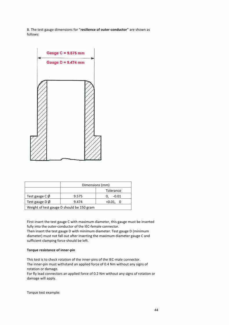
B. The test gauge dimensions for “resilience of outer-conductor” are shown as follows:
Dimensions (mm)
Tolerance
Test gauge C Ø 9.575 0, -0.01
Test gauge D Ø 9.474 +0.01, 0
Weight of test gauge D should be 150 gram
First insert the test gauge C with maximum diameter, this gauge must be inserted fully into the outer-conductor of the IEC-female connector. Then insert the test gauge D with minimum diameter. Test gauge D (minimum diameter) must not fall out after inserting the maximum diameter gauge C and sufficient clamping force should be left. Torque resistance of inner-pin This test is to check rotation of the inner-pins of the IEC-male connector. The inner-pin must withstand an applied force of 0.4 Nm without any signs of rotation or damage. For fly lead connectors an applied force of 0.2 Nm without any signs of rotation or damage will apply. Torque test example:
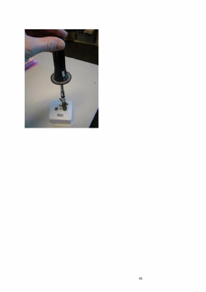
45

46
15 Appendix D: Cable clamp Description of centre conductor construction The type of the cable clamp and its centre conductor construction is depending on the manufacturer. The design of the centre conductor construction should be such that the inner conductor of the cable serves as the male contact. Physical dimensions Depending on supplier construction. Mechanical strength/withstand tightening torque N.a.. Test gauge acceptance cable clamp centre conductor construction The centre conductor construction of a cable clamp regarding Wall Outlets shall at least be able to accept male contacts/test gauges with a diameter range between 0.51-1.2 mm.
R 0,2 - 0,3 mm
8 mm
>3 mm
600
+/- 3
R 1,5 - 2 mm
applicable size
Clamp force/withdrawal test To verify that the centre conductor construction of the cable clamp does not suffer from deformation when mated with the range of inner conductors specified, a test has been advised which measures the force required to withdraw the selection of precision test gauges, out of the centre conductor under test.

47
Figure: Example of Clamp force test set up on F-connector
Spring construction only:
Wall Outlet centre conductor construction
Test sequence 1 2 3 4 5
Test gauge diameter (mm) 0.51 1.2 0.51 1.2 0.51
Clamping force min. (gram) 30 30
Clamping force tests must be performed with a duration of 10 seconds and at room temperature
Test gauge tolerance: +/- 0.01 mm
Spring construction in combination with fixing screw:
Wall Outlet centre conductor construction
Test sequence 1 2
Test gauge diameter (mm) 0.51 1.2
Clamping force min. (gram) 30 30
Clamping force tests must be performed with a duration of 10 seconds and at room temperature
Test gauge tolerance: +/- 0.01 mm
Insertion force test To verify that the centre conductor construction of the cable clamp does not suffer from deformation when mated with the range of inner conductors specified, a test has been advised which measures the force required to insert the selection of precision test gauges, into the centre conductor construction. Depending on test gauge diameter a sliding scale of the insertion force is presented in the table below:
48
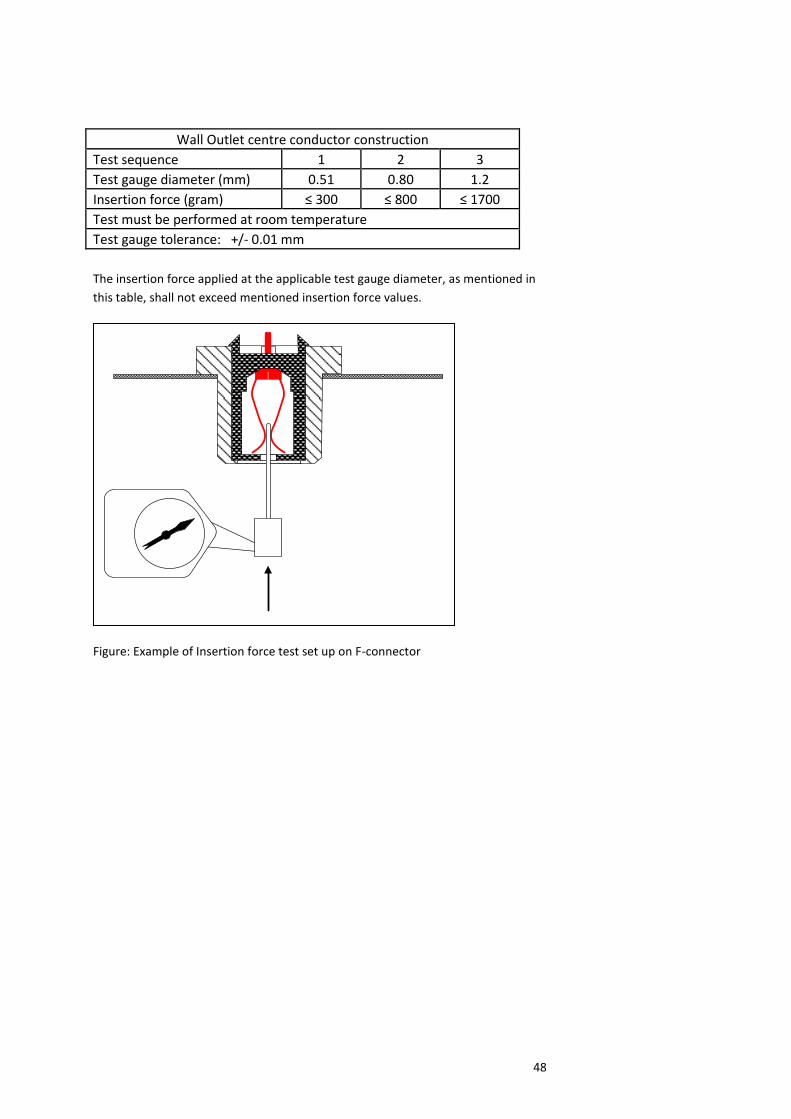
Wall Outlet centre conductor construction
Test sequence 1 2 3
Test gauge diameter (mm) 0.51 0.80 1.2
Insertion force (gram) ≤ 300 ≤ 800 ≤ 1700
Test must be performed at room temperature
Test gauge tolerance: +/- 0.01 mm
The insertion force applied at the applicable test gauge diameter, as mentioned in
this table, shall not exceed mentioned insertion force values.
Figure: Example of Insertion force test set up on F-connector

49
16 Appendix E: Pull force IEC female connector The pull force is the minimum force required to pull a IEC connector fully out without mechanical assistance. Pull force is deemed to be of primary importance in the measurement of the IEC connector. If too much force is required to remove the IEC connector then there is a greater possibility of damage to the wall outlet. If there is too little force required to remove the IEC connector then there is the risk of the plug just falling out or moving enough within for the signal to become intermittent. test procedure The Connector Under Test shall be new and unused. The extraction force testing should be undertaken after cycle testing. The ideal test uses a hardened steel mandrel conforming to the dimensions given in IEC 60169-2. No lubrication of the test mandrel is permitted for any of the tests listed.
Insert/Extract the test mandrel fully, co-axially with the jack, ensuring there is no side force applied.
Repeat for 10 insertion/extraction cycles.
Physically inspect the terminals and body of the CUT for wear, and test for electrical continuity.
If the CUT meets the pass/fail criteria, continue the test. Using a standard mandrel the extraction force is to be tested for the CUT.
Insert the test mandrel fully, co-axially with the jack, ensuring there is no side force applied.
Measure and record the extraction force. Pass/fail criteria:
The extraction force shall be within limits shown in clause 9.4.1.5.
Physically inspect the terminals and body of the CUT for wear, and test for electrical continuity.
50
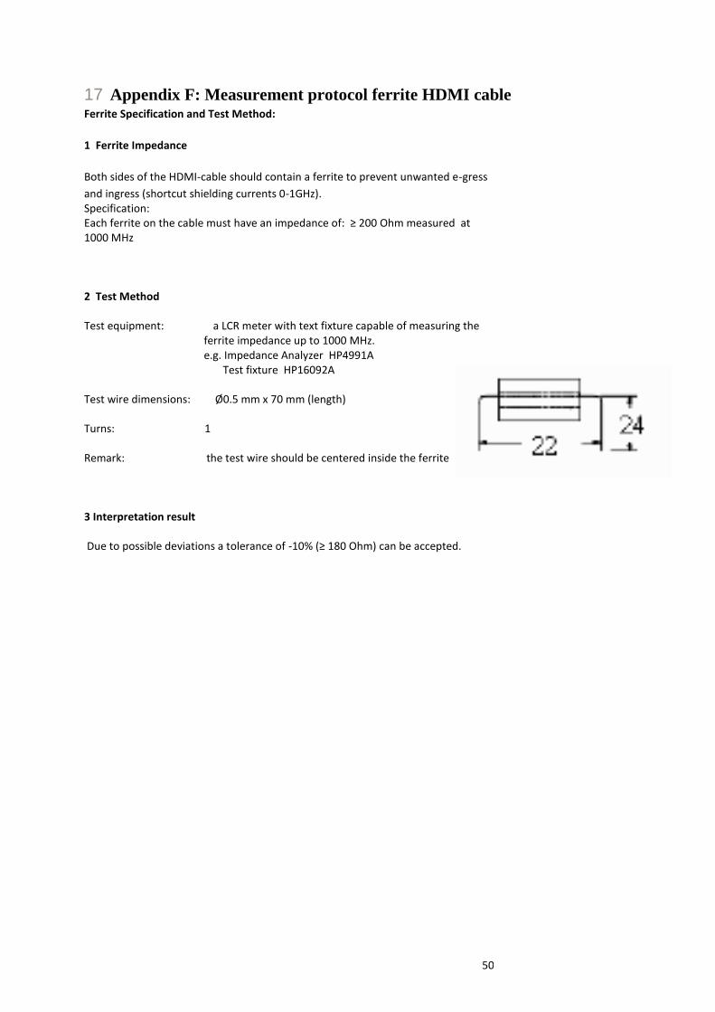
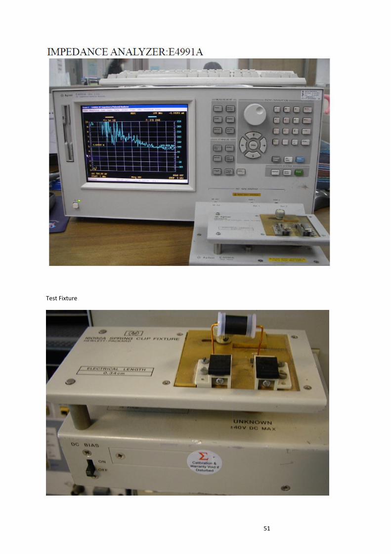
17 Appendix F: Measurement protocol ferrite HDMI cable Ferrite Specification and Test Method:
1 Ferrite Impedance
Both sides of the HDMI-cable should contain a ferrite to prevent unwanted e-gress
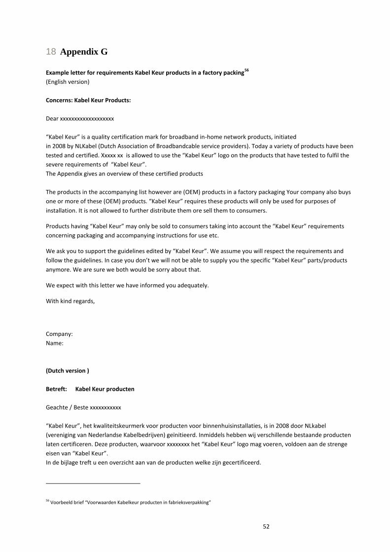
and ingress (shortcut shielding currents 0-1GHz). Specification: Each ferrite on the cable must have an impedance of: ≥ 200 Ohm measured at 1000 MHz 2 Test Method Test equipment: a LCR meter with text fixture capable of measuring the ferrite impedance up to 1000 MHz. e.g. Impedance Analyzer HP4991A Test fixture HP16092A Test wire dimensions: Ø0.5 mm x 70 mm (length) Turns: 1 Remark: the test wire should be centered inside the ferrite 3 Interpretation result Due to possible deviations a tolerance of -10% (≥ 180 Ohm) can be accepted.
51
Test Fixture
52
18 Appendix G
Example letter for requirements Kabel Keur products in a factory packing
56
(English version)
Concerns: Kabel Keur Products:
Dear xxxxxxxxxxxxxxxxxxx
“Kabel Keur” is a quality certification mark for broadband in-home network products, initiated
in 2008 by NLKabel (Dutch Association of Broadbandcable service providers). Today a variety of products have been
tested and certified. Xxxxx xx is allowed to use the “Kabel Keur” logo on the products that have tested to fulfil the
severe requirements of “Kabel Keur”.
The Appendix gives an overview of these certified products
The products in the accompanying list however are (OEM) products in a factory packaging Your company also buys
one or more of these (OEM) products. “Kabel Keur” requires these products will only be used for purposes of
installation. It is not allowed to further distribute them ore sell them to consumers.
Products having “Kabel Keur” may only be sold to consumers taking into account the “Kabel Keur” requirements
concerning packaging and accompanying instructions for use etc.
We ask you to support the guidelines edited by “Kabel Keur”. We assume you will respect the requirements and
follow the guidelines. In case you don’t we will not be able to supply you the specific “Kabel Keur” parts/products
anymore. We are sure we both would be sorry about that.
We expect with this letter we have informed you adequately.
With kind regards,
Company:
Name:
(Dutch version )
Betreft: Kabel Keur producten
Geachte / Beste xxxxxxxxxxx
“Kabel Keur”, het kwaliteitskeurmerk voor producten voor binnenhuisinstallaties, is in 2008 door NLkabel
(vereniging van Nederlandse Kabelbedrijven) geïnitieerd. Inmiddels hebben wij verschillende bestaande producten
laten certificeren. Deze producten, waarvoor xxxxxxxx het “Kabel Keur” logo mag voeren, voldoen aan de strenge
eisen van “Kabel Keur”.
In de bijlage treft u een overzicht aan van de producten welke zijn gecertificeerd.
56 Voorbeeld brief “Voorwaarden Kabelkeur producten in fabrieksverpakking”
53
De producten volgens bijgaande lijst zijn echter (OEM) producten in een fabrieksverpakking.
Ook uw bedrijf neemt een of meerdere van deze (OEM) producten af.
Volgens de voorwaarden die Kabel Keur stelt, mogen deze producten alleen gebruikt worden voor
installatiedoeleinden en is het niet toegestaan deze producten verder te distribueren c.q. te verkopen aan
consumenten en/of door te verkopen.
“Kabel Keur” producten die aan de consument worden geleverd, moeten voldoen aan de door NL Kabel in het kader
van het “Kabel Keur” gestelde eisen met betrekking tot de verpakking, gebruiksaanwijzing e.d.
Wij verzoeken u mee te werken aan de richtlijnen zoals Kabel Keur die heeft opgesteld.
Wij gaan er van uit dat u de voorwaarde zult respecteren en overeenkomstig zult handelen.
Het niet opvolgen hiervan zou anders inhouden dat wij de betreffende Kabel Keur producten niet meer aan u mogen
leveren. Voor alle partijen is dat uiteraard geen wenselijke situatie.
Wij vertrouwen erop u met deze brief op de juiste wijze op de hoogte te hebben gesteld.
Met vriendelijke groet,
xxxxxxxxxxxxxxxxx
Firma
Naam