Embed Size (px)
Citation preview
PVG 120Proportional Valves
Technical Information
2
Table of RevisionsDate Page Changed RevApr 2010 Various Layout, drawings and others HA
Sep 2010 29, 44 Drawing, new back cover HB
Sep 2011 All TOC moved all pages by one, Safety section, SD layout. IA
May 2012 22-23 Tables PVHC, PVE. IB
Jul 2012 42 PVM table data IC
Revision History, Contents
520L0356 • Rev IC • Jul 2012
PVG 120 Proportional ValveTechnical Information
© 2012 Sauer-Danfoss. All rights reserved.
Sauer-Danfoss accepts no responsibility for possible errors in catalogs, brochures and other printed material. Sauer -Danfoss reserves the right to alter its products without prior notice. This also applies to products already ordered provided that such alterations can be made without affecting agreed specifications. All trademarks in this material are properties of their respective owners. Sauer-Danfoss, the Sauer-Danfoss logotype, the Sauer-Danfoss S-icon, PLUS+1™, What really matters is inside® and Know-How in Motion™ are trademarks of the Sauer-Danfoss Group.
Frontpage: F301 112, F300 001, F300 009, F300 011, Drawing 155B569.eps
Contents
General Information
Function
Hydraulic Systems
Technical Data
Electrical Actuation
Valve system ..................................................................................................................................................... 4General characteristics ................................................................................................................................. 4Pump side module – PVP ............................................................................................................................ 4Basic module – PVB ....................................................................................................................................... 4Actuation modules ........................................................................................................................................ 4Remote controls units................................................................................................................................... 5Electronic accessories ................................................................................................................................... 5
PVG 120 with Open Centre PVP ................................................................................................................ 6PVG 120 with Closed Centre PVP .............................................................................................................. 6PVG 120 Sectional Drawing ........................................................................................................................ 7
Examples ........................................................................................................................................................... 8
PVG 120 Valve Group ..................................................................................................................................10Mechanical Actuation PVM .......................................................................................................................10Hydraulic Actuation PVH ...........................................................................................................................10PVE, Electrical Actuation ...........................................................................................................................11PVEO ..................................................................................................................................................................11PVEH ..................................................................................................................................................................11PVPE, Electrical Relief Valve, Normally Open ......................................................................................12
PVEO, ON-OFF ................................................................................................................................................13PVEH, Proportional High ............................................................................................................................13PVEH, LVDT-Transducer ..............................................................................................................................14PVEH, Pulse Width Modulation ................................................................................................................14PVEH, Fault Monitoring ..............................................................................................................................14Fault Monitoring Specification ................................................................................................................15PVEH, Connection to Fault Monitoring Output .................................................................................16
3520L0356 • Rev IC • Jul 2012
PVG 120 Proportional ValveTechnical InformationContents
PVP and PVPV, Pump Side Modules ......................................................................................................17PVP, Accessories for Open Centre Pump Side Modules .................................................................18PVB, Basic Modules ......................................................................................................................................19PVB, Accessories for Basic Modules ......................................................................................................20PVLP, Shock and Suction Valves for A and B Port Connections....................................................21PVLA, Suction Valve .....................................................................................................................................21PVBS, Main Spools ........................................................................................................................................22PVM, Mechanical Actuation ......................................................................................................................22PVMD, Cover for Mechanical Actuation ...............................................................................................22PVH, Hydraulic Actuation ..........................................................................................................................23PVH, High Current Actuator ......................................................................................................................23PVE, Electrical Actuation ............................................................................................................................23PVT, Tank Side Modul .................................................................................................................................24PVAS, Assembly Kit ......................................................................................................................................24Modules for Oil Flow Exceeding 180 l/min [47.6 US gal/min] ......................................................25
Pump with fixed displacement ..........................................................................................................25Pump with variable displacement ....................................................................................................25
General .............................................................................................................................................................26PVP, Pump Side Module .............................................................................................................................26PVB, Basic Module ........................................................................................................................................27PVLP, Shock Valve (Pressure Relief Valve in PVLP) .............................................................................29PVLP/PVLA, Suction Function ..................................................................................................................29
Valve Dimensions .........................................................................................................................................30General Dimensions ....................................................................................................................................31
PVM, Lever Positions ...................................................................................................................................32
Building in Safety .........................................................................................................................................33FMEA (Failure Mode and Effect Analysis) IEC EN 61508 ............................................................33Hazard and Risk Analysis ISO 12100-1 / 14121.............................................................................33
Control System Example ............................................................................................................................34PVG32 – Mainly used in system with fixed displacement pumps .........................................36PVG100 – Alternative LS dump or pilot supply disconnect .....................................................36PVG120 – Pump disconnect/block for variable pumps ............................................................36
Oil, Particle Content, Degree of Contamination ................................................................................38Mineral oil, Non-flammable fluids, Biodegradable oils .............................................................38
Filtering ............................................................................................................................................................39Conversion Factors ......................................................................................................................................39
Order Form .....................................................................................................................................................40Reordering .................................................................................................................................................41
Module Selection Chart .............................................................................................................................42
Modules and Code Numbers
Technical Characteristics
Dimensions
Lever Positions
Safety in Application
Other Operating Conditions
Order Specification
Module Selection Chart
4 520L0356 • Rev IC • Jul 2012
PVG 120 Proportional ValveTechnical Information
General
General Information
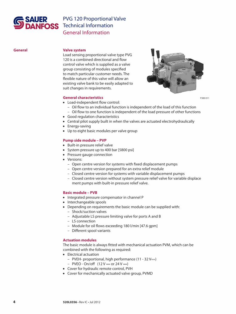
Valve systemLoad sensing proportional valve type PVG 120 is a combined directional and flow control valve which is supplied as a valve group consisting of modules specified to match particular customer needs. The flexible nature of this valve will allow an existing valve bank to be easily adapted to suit changes in requirements.
General characteristics• Load-independent flow control:
– Oil flow to an individual function is independent of the load of this function – Oil flow to one function is independent of the load pressure of other functions
• Good regulation characteristics• Central pilot supply built in when the valves are actuated electrohydraulically• Energy-saving• Up to eight basic modules per valve group
Pump side module – PVP• Built-in pressure relief valve• System pressure up to 400 bar [5800 psi]• Pressure gauge connection• Versions:
– Open centre version for systems with fixed displacement pumps – Open centre version prepared for an extra relief module – Closed centre version for systems with variable displacement pumps – Closed centre version without system pressure relief valve for variable displace
ment pumps with built-in pressure relief valve.
Basic module – PVB• Integrated pressure compensator in channel P• Interchangeable spools• Depending on requirements the basic module can be supplied with:
– Shock/suction valves – Adjustable LS pressure limiting valve for ports A and B – LS connection – Module for oil flows exceeding 180 l/min [47.6 gpm] – Different spool variants
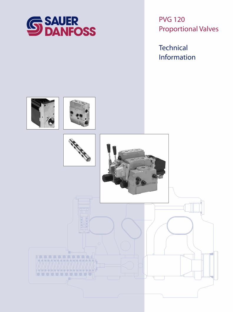
Actuation modulesThe basic module is always fitted with mechanical actuation PVM, which can be combined with the following as required:• Electrical actuation
– PVEH- proportional, high performance (11 - 32 V––__) – PVEO - On/off (12 V ––__ or 24 V ––__)
• Cover for hydraulic remote control, PVH• Cover for mechanically actuated valve group, PVMD
F300 011
5520L0356 • Rev IC • Jul 2012
PVG 120 Proportional ValveTechnical Information
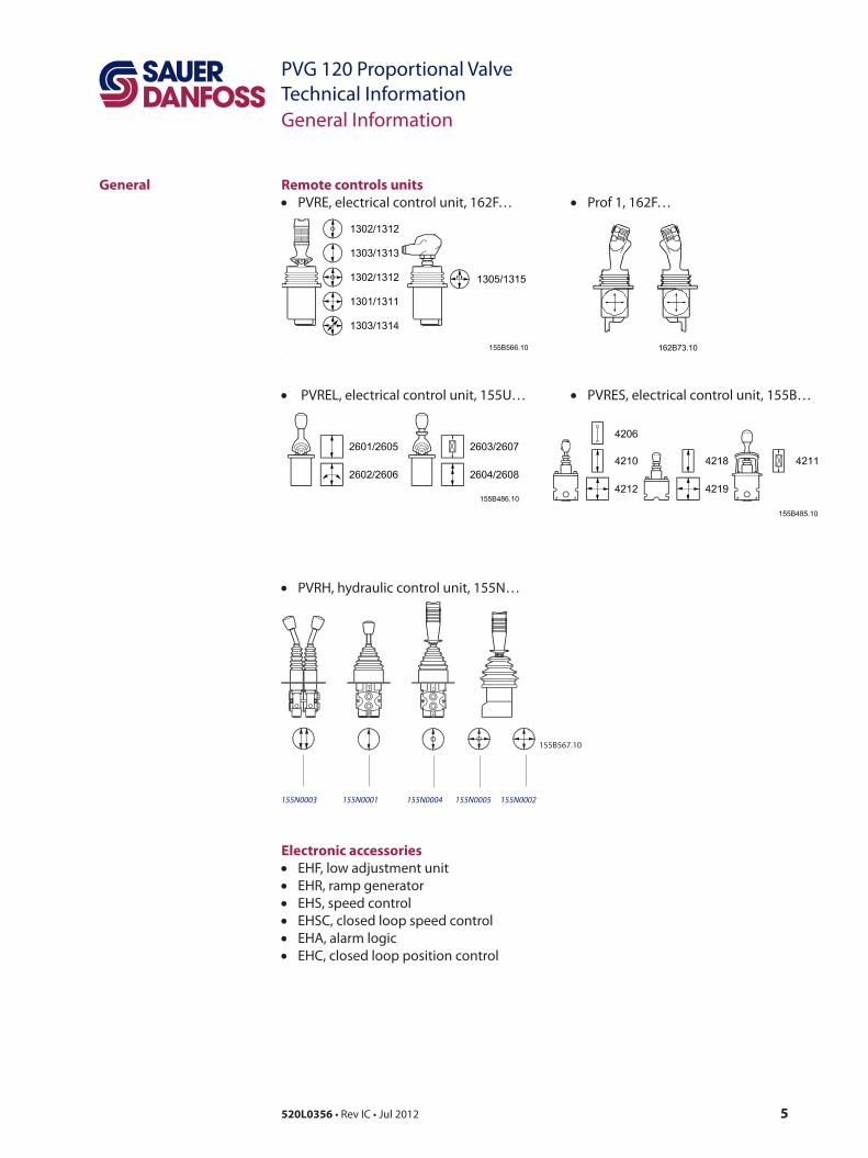
Remote controls units• PVRE, electrical control unit, 162F… • Prof 1, 162F…
• PVREL, electrical control unit, 155U… • PVRES, electrical control unit, 155B…
• PVRH, hydraulic control unit, 155N…
155N0003 155N0001 155N0004 155N0005 155N0002
Electronic accessories• EHF, low adjustment unit• EHR, ramp generator• EHS, speed control• EHSC, closed loop speed control• EHA, alarm logic• EHC, closed loop position control
General
General Information
155B567.10
6 520L0356 • Rev IC • Jul 2012
PVG 120 Proportional ValveTechnical Information
PVG 120 with Open Centre PVP
PVG 120 with Closed Centre PVP
Function
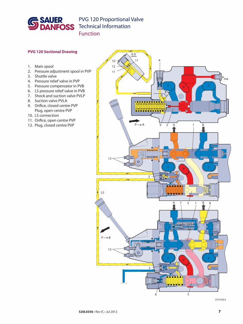
When the pump is started and the main spools (1) in the individual basic modules are in neutral position, oil flows from the pump, through connection P, across the pressure adjustment spool (2) to tank.The oil flow led across the pressure adjustment spool determines the pump pressure (stand-by pressure). If a reduced stand-by pressure is required, an extra relief valve PVPH or PVPE can be used in PVP (see characteristics for neutral flow pressure, page 25).
When the main spools are actuated the highest load pressure is distributed across the shuttle valve circuit (3) to the spring chamber behind the pressure adjustment spool (2) and completely or partly closes the connection to tank.
The pump pressure is applied to the right-hand side of the pressure adjustment spool (2). The pressure relief valve (4) opens when the load pressure exceeds the set value, allowing pump flow to be diverted back to tank.
In the basic module the compensator (5) maintains a constant pressure drop across the main spool – both when the load changes and when a module with a higher load pressure is activated.
Shock and suction valves with a fixed setting (7) and the suction valves (8) on ports A and B are used to protect individual working functions against overload.
In the basic module it is possible to build in an adjustable LS pressure relief valve (6) to limit the pressure from each working function. The LS pressure limiting valve saves energy:• Without LS pressure limiting valve all the oil flow to the working function will be led
across the combined shock and suction valves to tank if the pressure exceeds the fixed setting of the valves.
• With LS pressure limiting valve an oil flow of only about 2 l/min [0.5 US gal/min] will be led across the LS pressure limiting valve to tank if the pressure exceeds the valve setting.
In the closed centre version an orifice (9) has been fitted instead of the plug. This means that the pressure adjustment spool (2) will only open to tank when the pressure in channel P exceeds the pressure relief valve setting (4).
In load sensing systems the load pressure is led to the pump regulator via the LS connec-tion (10). So the orifices (11) have been removed, and a plug (12) has been fitted instead of one of the orifices.
In neutral position the pump regulator will set the displacement so that leakage in the system is just compensated for.
When a main spool is activated, the pump regulator will adjust the displacement so that the set differential pressure between P and LS is maintained.
The pressure relief valve (4) in PVP is set for a pressure of about 30 bar [435 psi] above maximum system pressure (set at the pump or an external pressure relief valve).If the system or the pump regulation has a pressure relief valve, it is possible to use a PVPV pump side module, without integrated pressure adjustment spool and pressure relief valve.
7520L0356 • Rev IC • Jul 2012
PVG 120 Proportional ValveTechnical InformationFunction
PVG 120 Sectional Drawing
410
12
11
11
X-X
XX
P A
V310100.A
9 2 1
T P T
pma
A B
A B
3
7 5 1 8
T P T
13
6 5
LS
T P T
3
13
P B
1. Main spool2. Pressure adjustment spool in PVP3. Shuttle valve4. Pressure relief valve in PVP5. Pressure compensator in PVB6. LS pressure relief valve in PVB7. Shock and suction valve PVLP8. Suction valve PVLA9. Orifice, closed centre PVP
Plug, open centre PVP10. LS connection11. Orifice, open centre PVP12. Plug, closed centre PVP
8 520L0356 • Rev IC • Jul 2012
PVG 120 Proportional ValveTechnical InformationHydraulic Systems
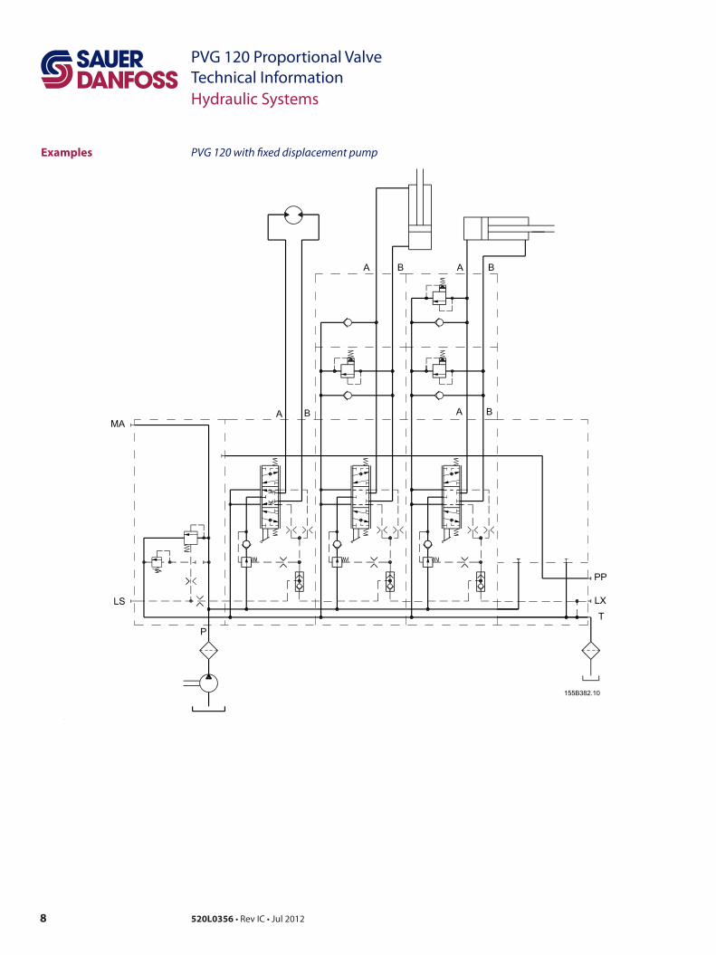
Examples PVG 120 with fixed displacement pump
9520L0356 • Rev IC • Jul 2012
PVG 120 Proportional ValveTechnical InformationHydraulic Systems
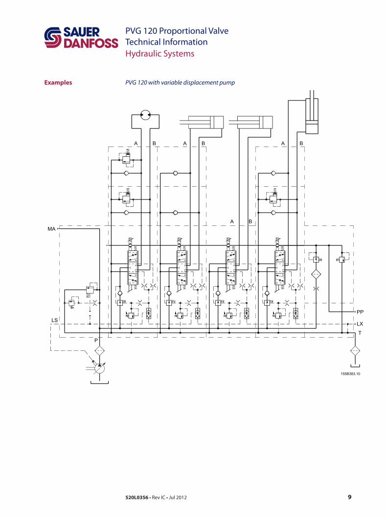
Examples PVG 120 with variable displacement pump
10 520L0356 • Rev IC • Jul 2012
PVG 120 Proportional ValveTechnical InformationTechnical Data
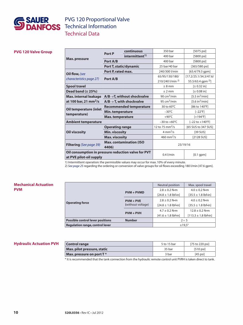
PVG 120 Valve Group
Mechanical Actuation PVM
Hydraulic Actuation PVH
Max. pressure
Port Pcontinuous 350 bar [5075 psi]
intermittent1) 400 bar [5800 psi]
Port A/B 400 bar [5800 psi]
Port T, static/dynamic 25 bar/40 bar [365/580 psi]
Oil flow, (see characteristics page 27)
Port P, rated max. 240/300 l/min [63.4/79.3 gpm]
Port A/B65/95/130/180/
210/240 l/min 2)
[17.2/25.1/34.3/47.6/
55.5/63.4 gpm 2)]
Spool travel ± 8 mm [± 0.32 in]
Dead band (± 25%) ± 2 mm [± 0.08 in]
Max. internal leakage at 100 bar, 21 mm2/s
A/B→T, without shockvalve 90 cm3/min [5.5 in3/min]
A/B→ T, with shockvalve 95 cm3/min [5.6 in3/min]
Oil temperature (inlet temperature)
Recommended temperature 30 to 60°C [86 to 140°F]
Min. temperature –30°C [–22°F]
Max. temperature +90°C [+194°F]
Ambient temperature –30 to +60°C [–22 to +140°F]
Oil viscosity
Operating range 12 to 75 mm2/s [65 SUS to 347 SUS]
Min. viscosity 4 mm2/s [39 SUS]
Max. viscosity 460 mm2/s [2128 SUS]
Filtering (See page 39)Max. contamination (ISO 4406)
23/19/16
Oil consumption in pressure reduction valve for PVT at PVE pilot-oil supply
0.4 l/min [0.1 gpm]
1) Intermittent operation: the permissible values may occur for max. 10% of every minute. 2) See page 25 regarding the ordering or conversion of valve groups for oil flows exceeding 180 l/min [47.6 gpm].
Neutral position Max. spool travel
Operating force
PVM + PVMD2.8 ± 0.2 N•m
[24.8 ± 1.8 lbf•in]4.0 ± 0.2 N•m
[35.5 ± 1.8 lbf•in]
PVM + PVE (without voltage)
2.8 ± 0.2 N•m[24.8 ± 1.8 lbf•in]
4.0 ± 0.2 N•m[35.5 ± 1.8 lbf•in]
PVM + PVH4.7 ± 0.2 N•m
[41.6 ± 1.8 lbf•in]12.8 ± 0.2 N•m
[113.3 ± 1.8 lbf•in]Possible control lever positions Number 2 × 5Regulation range, control lever ±19,5°
Control range 5 to 15 bar [75 to 220 psi]
Max. pilot pressure, static 35 bar [510 psi]
Max. pressure on port T * 3 bar [45 psi]
* It is recommended that the tank connection from the hydraulic remote control unit PVRH is taken direct to tank.
11520L0356 • Rev IC • Jul 2012
PVG 120 Proportional ValveTechnical InformationTechnical Data
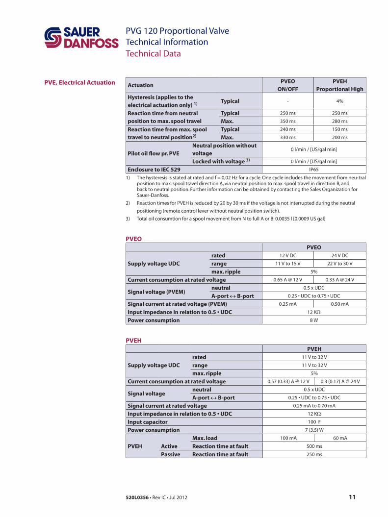
PVE, Electrical Actuation ActuationPVEO
ON/OFFPVEH
Proportional High
Hysteresis (applies to the electrical actuation only) 1) Typical - 4%
Reaction time from neutral position to
max. spool travel
Typical 250 ms 250 ms
Max. 350 ms 280 ms
Reaction time from max. spool travel to neutral position2)
Typical 240 ms 150 ms
Max. 330 ms 200 ms
Pilot oil flow pr. PVENeutral position without voltage
0 l/min / [US/gal min]
Locked with voltage 3) 0 l/min / [US/gal min]
Enclosure to IEC 529 IP65
1) The hysteresis is stated at rated and f = 0,02 Hz for a cycle. One cycle includes the movement from neu- tral position to max. spool travel direction A, via neutral position to max. spool travel in direction B, and back to neutral position. Further information can be obtained by contacting the Sales Organization for Sauer-Danfoss.
2) Reaction times for PVEH is reduced by 20 by 30 ms if the voltage is not interrupted during the neutral
positioning (remote control lever without neutral position switch).
3) Total oil consumtion for a spool movement from N to full A or B: 0.0035 l [0.0009 US gal]
PVEOPVEO
Supply voltage UDC
rated 12 V DC 24 V DC
range 11 V to 15 V 22 V to 30 V
max. ripple 5%
Current consumption at rated voltage 0.65 A @ 12 V 0.33 A @ 24 V
Signal voltage (PVEM)neutral 0.5 x UDC
A-port ↔ B-port 0.25 • UDC to 0.75 • UDC
Signal current at rated voltage (PVEM) 0.25 mA 0.50 mA
Input impedance in relation to 0.5 • UDC 12 KΩ
Power consumption 8 W
PVEHPVEH
Supply voltage UDC
rated 11 V to 32 V
range 11 V to 32 V
max. ripple 5%
Current consumption at rated voltage 0.57 (0.33) A @ 12 V 0.3 (0.17) A @ 24 V
Signal voltageneutral 0.5 x UDC
A-port ↔ B-port 0.25 • UDC to 0.75 • UDC
Signal current at rated voltage 0.25 mA to 0.70 mA
Input impedance in relation to 0.5 • UDC 12 KΩ
Input capacitor 100 ηF
Power consumption 7 (3.5) W
PVEH
Max. load 100 mA 60 mA
Active Reaction time at fault 500 ms
Passive Reaction time at fault 250 ms
12 520L0356 • Rev IC • Jul 2012
PVG 120 Proportional ValveTechnical InformationTechnical Data
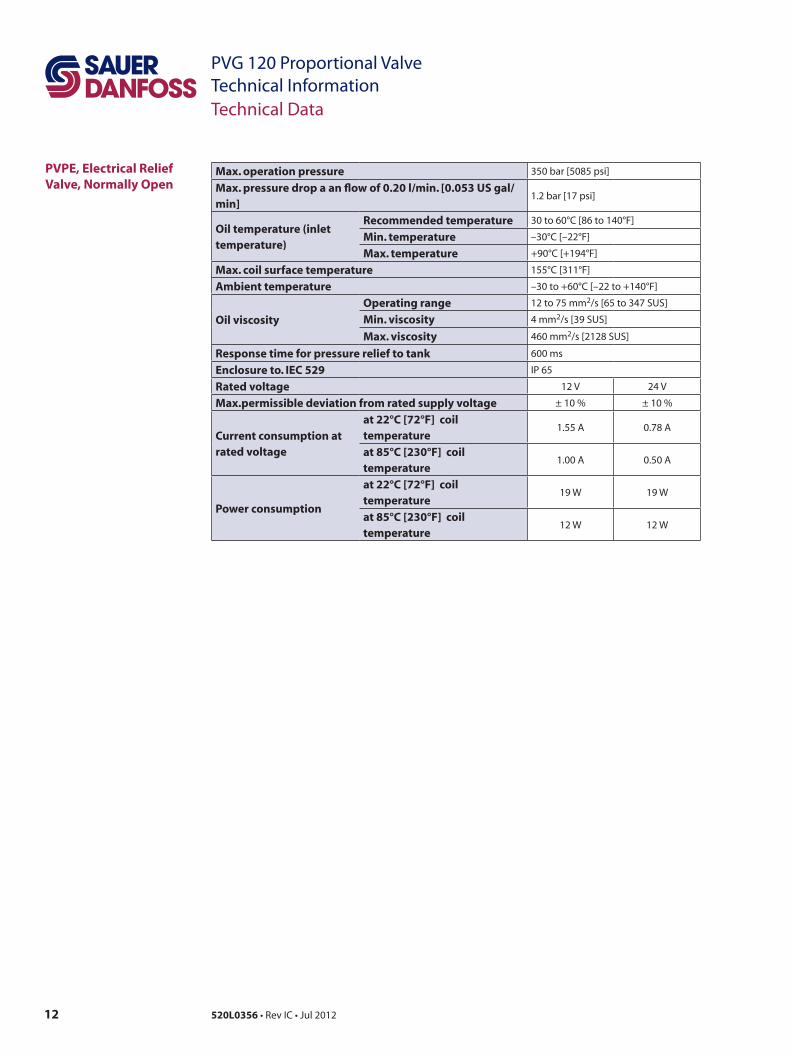
PVPE, Electrical Relief Valve, Normally Open
Max. operation pressure 350 bar [5085 psi]
Max. pressure drop a an flow of 0.20 l/min. [0.053 US gal/min]
1.2 bar [17 psi]
Oil temperature (inlet temperature)
Recommended temperature 30 to 60°C [86 to 140°F]
Min. temperature –30°C [–22°F]
Max. temperature +90°C [+194°F]
Max. coil surface temperature 155°C [311°F]
Ambient temperature –30 to +60°C [–22 to +140°F]
Oil viscosity
Operating range 12 to 75 mm2/s [65 to 347 SUS]
Min. viscosity 4 mm2/s [39 SUS]
Max. viscosity 460 mm2/s [2128 SUS]
Response time for pressure relief to tank 600 ms
Enclosure to. IEC 529 IP 65
Rated voltage 12 V 24 V
Max.permissible deviation from rated supply voltage ± 10 % ± 10 %
Current consumption at rated voltage
at 22°C [72°F] coil temperature
1.55 A 0.78 A
at 85°C [230°F] coil temperature
1.00 A 0.50 A
Power consumption
at 22°C [72°F] coil temperature
19 W 19 W
at 85°C [230°F] coil temperature
12 W 12 W
13520L0356 • Rev IC • Jul 2012
PVG 120 Proportional ValveTechnical Information
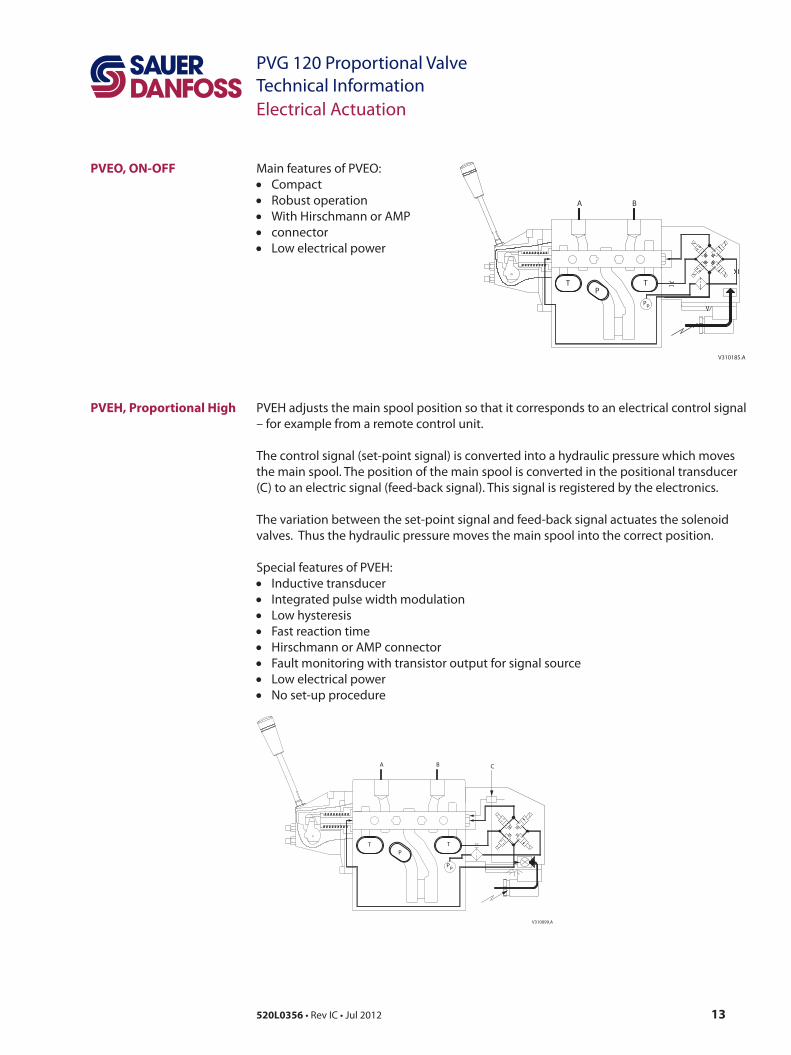
Main features of PVEO: • Compact• Robust operation• With Hirschmann or AMP • connector• Low electrical power
Electrical Actuation
PVEO, ON-OFF
PVEH, Proportional High
V310185.A
P
A
TP
T
p
B
V310099.A
P
A
TP
T
B
p
C
PVEH adjusts the main spool position so that it corresponds to an electrical control signal – for example from a remote control unit.
The control signal (set-point signal) is converted into a hydraulic pressure which moves the main spool. The position of the main spool is converted in the positional transducer (C) to an electric signal (feed-back signal). This signal is registered by the electronics.
The variation between the set-point signal and feed-back signal actuates the solenoid valves. Thus the hydraulic pressure moves the main spool into the correct position.
Special features of PVEH:• Inductive transducer• Integrated pulse width modulation• Low hysteresis• Fast reaction time• Hirschmann or AMP connector• Fault monitoring with transistor output for signal source• Low electrical power• No set-up procedure
14 520L0356 • Rev IC • Jul 2012
PVG 120 Proportional ValveTechnical Information
LVDT, Inductive transducer (Linear Variable Differential Transformer)When the main spool is moved a voltage is induced proportional to the spool position. The use of LVDT gives contact-free (proximity) registration of the main spool position. This means an extra-long working life and no limitation as regards the type of hydraulic fluid used. In addition, LVDT gives a precise position signal of high resolution.
Integrated pulse width modulationPositioning of the main spool in PVEH is based on the pulse width modulation principle. As soon as the main spool reaches the required position, modulation stops and the spool is locked in position.
A fault monitoring system is provided in all PVEA, PVEH and PVES modules. The system is available in two versions: • The active fault monitoring type, which provides a warning signal, deactivates the
solenoid valves and drives the spool in neutral. • The passive fault monitoring type, which provides a warning signal only. Both active and passive fault monitoring systems are triggered by three main events:
1. Input signal monitoringThe input signal voltage is continuously monitored. The permissible range is between 15% and 85% of the supply voltage. Outside this range the section will switch into an active error state. 2. Transducer supervisionIf one of the wires to the LVDT sensor is broken or short-circuited, the section will switch into an active error state.
3. Supervision of the closed loopThe actual position must always correspond to the demanded position (input signal). If the actual spool position is further than the demanded spool position (>12%, PVEA: >25%), the system detects an error and will switch into an active error state. On the other hand, a situation where the actual position is closer to neutral than that demanded will not cause an error state. This situation is considered “in control”.When an active error state occurs, the fault monitoring logic will be triggered:
Active fault monitoring• A delay of 500 ms (PVEA: 750 ms) before anything happens.• The solenoid valve bridge will be disabled and all solenoid valves will be released.• An alarm signal is sent out through the appropriate pin connection.• This state is memorized and continues until the system is actively reset (by turning off
the supply voltage).
Passive fault monitoring • A delay of 250 ms (PVEA: 750 ms) before anything happens. • The solenoid valve bridge will not be disabled but still control the main spool position.• An alarm signal is sent out through the appropriate pin connection.• This state is not memorized. When the erroneous state disappears, the alarm signal
will turn to passive again. However, the signal will always be active for a minimum of 100 ms when triggered.
PVEH, LVDT-Transducer
PVEH, Pulse Width Modulation
PVEH,Fault Monitoring
Electrical Actuation
15520L0356 • Rev IC • Jul 2012
PVG 120 Proportional ValveTechnical Information
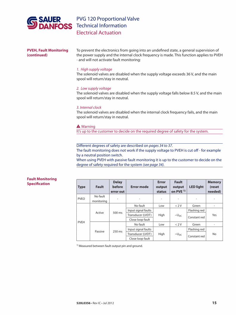
To prevent the electronics from going into an undefined state, a general supervision of the power supply and the internal clock frequency is made. This function applies to PVEH - and will not activate fault monitoring:
1. High supply voltageThe solenoid valves are disabled when the supply voltage exceeds 36 V, and the main spool will return/stay in neutral.
2. Low supply voltageThe solenoid valves are disabled when the supply voltage falls below 8.5 V, and the main spool will return/stay in neutral.
3. Internal clockThe solenoid valves are disabled when the internal clock frequency fails, and the main spool will return/stay in neutral.
WWarningIt’s up to the customer to decide on the required degree of safety for the system.
Different degrees of safety are described on pages 34 to 37. The fault monitoring does not work if the supply voltage to PVEH is cut off - for example by a neutral position switch. When using PVEH with passive fault monitoring it is up to the customer to decide on the degree of safety required for the system (see page 34).
Type FaultDelay
before error out
Error modeError
output status
Fault output
on PVE 1)LED light
Memory (reset
needed)
PVEONo fault
monitoring- - - - - -
PVEH
Active 500 ms
No fault Low < 2 V Green -
Input signal faults
High ∼UDC
Flashing red
YesTransducer (LVDT)Constant red
Close loop fault
Passive 250 ms
No fault Low < 2 V Green -
Input signal faults
High ~UDC
Flashing red
NoTransducer (LVDT)Constant red
Close loop fault
1) Measured between fault output pin and ground.
PVEH, Fault Monitoring (continued)
Fault Monitoring Specification
Electrical Actuation
16 520L0356 • Rev IC • Jul 2012
PVG 120 Proportional ValveTechnical Information
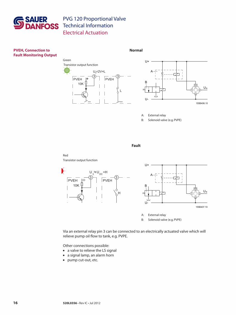
PVEH, Connection to Fault Monitoring Output
Electrical Actuation
Normal
Green
Transistor output function
Fault
Red
Transistor output function
A: External relay
B: Solenoid valve (e.g. PVPE)
A: External relay
B: Solenoid valve (e.g. PVPE)
Via an external relay pin 3 can be connected to an electrically actuated valve which will relieve pump oil flow to tank, e.g. PVPE.
Other connections possible:• a valve to relieve the LS signal• a signal lamp, an alarm horn• pump cut-out, etc.
17520L0356 • Rev IC • Jul 2012
PVG 120 Proportional ValveTechnical Information
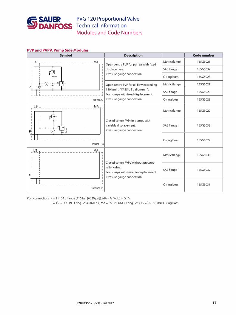
PVP and PVPV, Pump Side Modules Symbol Description Code number
Open centre PVP for pumps with fixed displacement. Pressure gauge connection.
Metric flange 155G5021
SAE flange 155G5037
O-ring boss 155G5023
Open centre PVP for oil flow exceeding 180 l/min. [47.55 US gallon/min]. For pumps with fixed displacement. Pressure gauge connection
Metric flange 155G5027
SAE flange 155G5029
O-ring boss 155G5028
Closed centre PVP for pumps with variable displacement. Pressure gauge connection.
Metric flange 155G5020
SAE flange 155G5038
O-ring boss 155G5022
Closed centre PVPV without pressure relief valve. For pumps with variable displacement. Pressure gauge connection
Metric flange 155G5030
SAE flange 155G5032
O-ring boss 155G5031
Port connections: P = 1 in SAE flange (415 bar [6020 psi]); MA = G 1/4; LS = G 3/8
P = 11/16 - 12 UN O-ring Boss 6020 psi; MA = 1/2 - 20 UNF O-ring Boss; LS = 3/4 - 16 UNF O-ring Boss
Modules and Code Numbers
18 520L0356 • Rev IC • Jul 2012
PVG 120 Proportional ValveTechnical Information
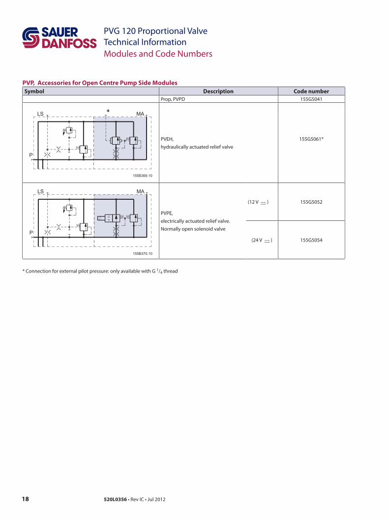
PVP, Accessories for Open Centre Pump Side ModulesSymbol Description Code number
Prop, PVPD 155G5041
PVEH, hydraulically actuated relief valve
155G5061*
PVPE, electrically actuated relief valve.Normally open solenoid valve
(12 V ––__ ) 155G5052
(24 V ––__ ) 155G5054
* Connection for external pilot pressure: only available with G 1/4 thread
Modules and Code Numbers
19520L0356 • Rev IC • Jul 2012
PVG 120 Proportional ValveTechnical InformationModules and Code Numbers
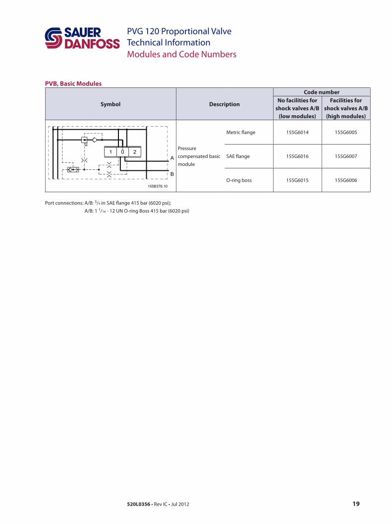
PVB, Basic Modules
Symbol Description
Code numberNo facilities for
shock valves A/B (low modules)
Facilities for shock valves A/B (high modules)
Pressure compensated basic module
Metric flange 155G6014 155G6005
SAE flange 155G6016 155G6007
O-ring boss 155G6015 155G6006
Port connections: A/B: 3/4 in SAE flange 415 bar (6020 psi); A/B: 1 1/16 - 12 UN O-ring Boss 415 bar (6020 psi)
20 520L0356 • Rev IC • Jul 2012
PVG 120 Proportional ValveTechnical Information
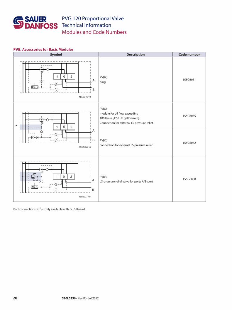
PVB, Accessories for Basic Modules Symbol Description Code number
PVBP, plug
155G6081
PVBU, module for oil flow exceeding 180 l/min [47.6 US gallon/min]. Connection for external LS pressure relief.
155G6035
PVBC, connection for external LS pressure relief.
155G6082
PVBR, LS-pressure relief valve for ports A/B-port
155G6080
Port connections: G 1/4: only available with G 1/4 thread
Modules and Code Numbers
21520L0356 • Rev IC • Jul 2012
PVG 120 Proportional ValveTechnical Information
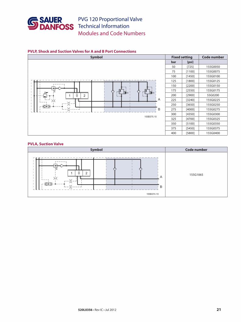
PVLP, Shock and Suction Valves for A and B Port ConnectionsSymbol Fixed setting Code number
bar [psi]50 [725] 155G005075 [1100] 155G0075
100 [1450] 155G0100125 [1800] 155G0125150 [2200] 155G0150175 [2550] 155G0175200 [2900] 55G0200225 [3240] 155G0225250 [3650] 155G0250275 [4000] 155G0275300 [4350] 155G0300325 [4700] 155G0325350 [5100] 155G0350375 [5450] 155G0375400 [5800] 155G0400
PVLA, Suction ValveSymbol Code number
155G1065
Modules and Code Numbers
22 520L0356 • Rev IC • Jul 2012
PVG 120 Proportional ValveTechnical Information
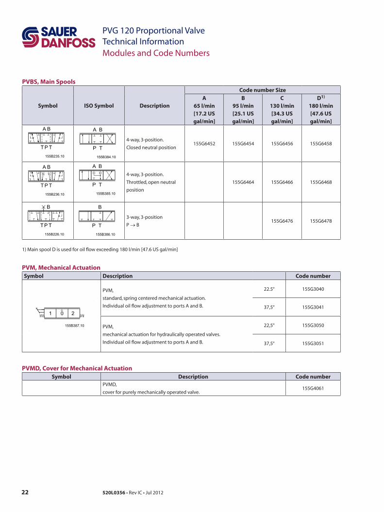
PVM, Mechanical ActuationSymbol Description Code number
PVM,
standard, spring centered mechanical actuation.
Individual oil flow adjustment to ports A and B.
22.5° 155G3040
37,5° 155G3041
PVM,
mechanical actuation for hydraulically operated valves.
Individual oil flow adjustment to ports A and B.
22,5° 155G3050
37,5° 155G3051
PVMD, Cover for Mechanical ActuationSymbol Description Code number
PVMD,
cover for purely mechanically operated valve. 155G4061
PVBS, Main Spools
Symbol ISO Symbol Description
Code number Size
A65 l/min[17.2 USgal/min]
B95 l/min[25.1 USgal/min]
C130 l/min[34.3 USgal/min]
D1)
180 l/min[47.6 USgal/min]
4-way, 3-position.
Closed neutral position155G6452 155G6454 155G6456 155G6458
4-way, 3-position.
Throttled, open neutral
position
155G6464 155G6466 155G6468
3-way, 3-position
P → B155G6476 155G6478
1) Main spool D is used for oil flow exceeding 180 l/min [47.6 US gal/min]
Modules and Code Numbers
23520L0356 • Rev IC • Jul 2012
PVG 120 Proportional ValveTechnical InformationModules and Code Numbers
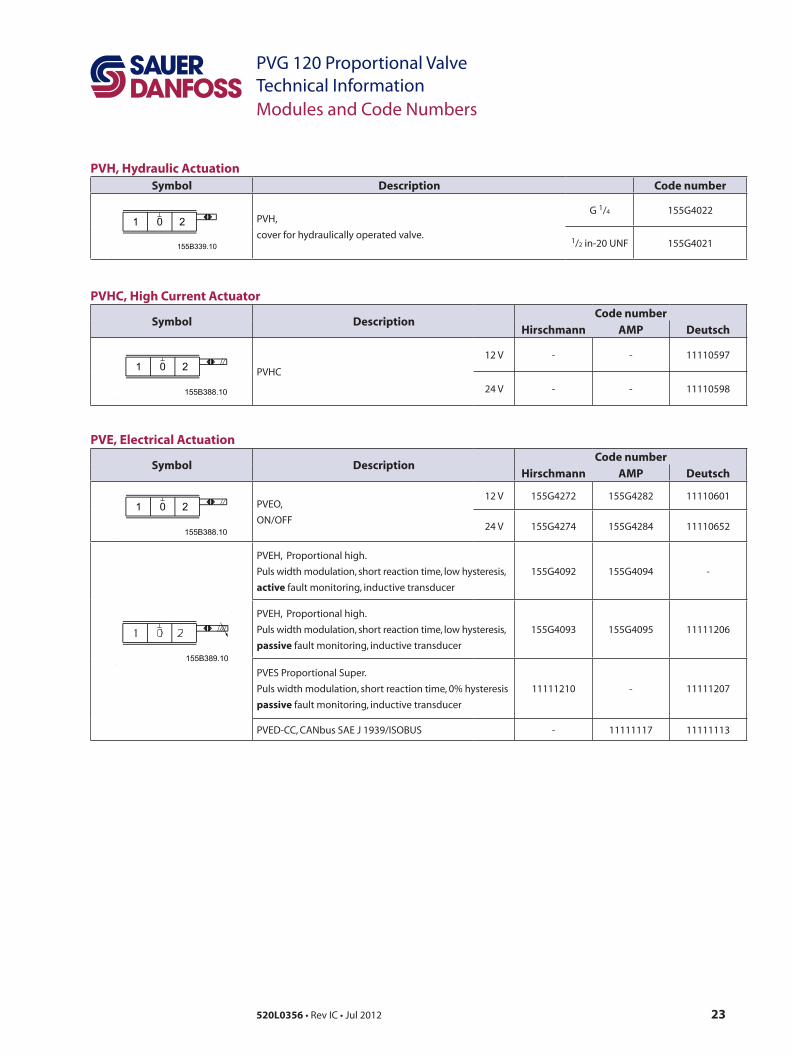
PVH, Hydraulic ActuationSymbol Description Code number
PVH,
cover for hydraulically operated valve.
G 1/4 155G4022
1/2 in-20 UNF 155G4021
PVHC, High Current Actuator
Symbol DescriptionCode number
Hirschmann AMP Deutsch
PVHC
12 V - - 11110597
24 V - - 11110598
PVE, Electrical Actuation
Symbol DescriptionCode number
Hirschmann AMP Deutsch
PVEO,
ON/OFF
12 V 155G4272 155G4282 11110601
24 V 155G4274 155G4284 11110652
PVEH, Proportional high.
Puls width modulation, short reaction time, low hysteresis,
active fault monitoring, inductive transducer
155G4092 155G4094 -
PVEH, Proportional high.
Puls width modulation, short reaction time, low hysteresis,
passive fault monitoring, inductive transducer
155G4093 155G4095 11111206
PVES Proportional Super.
Puls width modulation, short reaction time, 0% hysteresis
passive fault monitoring, inductive transducer
11111210 - 11111207
PVED-CC, CANbus SAE J 1939/ISOBUS - 11111117 11111113
24 520L0356 • Rev IC • Jul 2012
PVG 120 Proportional ValveTechnical Information
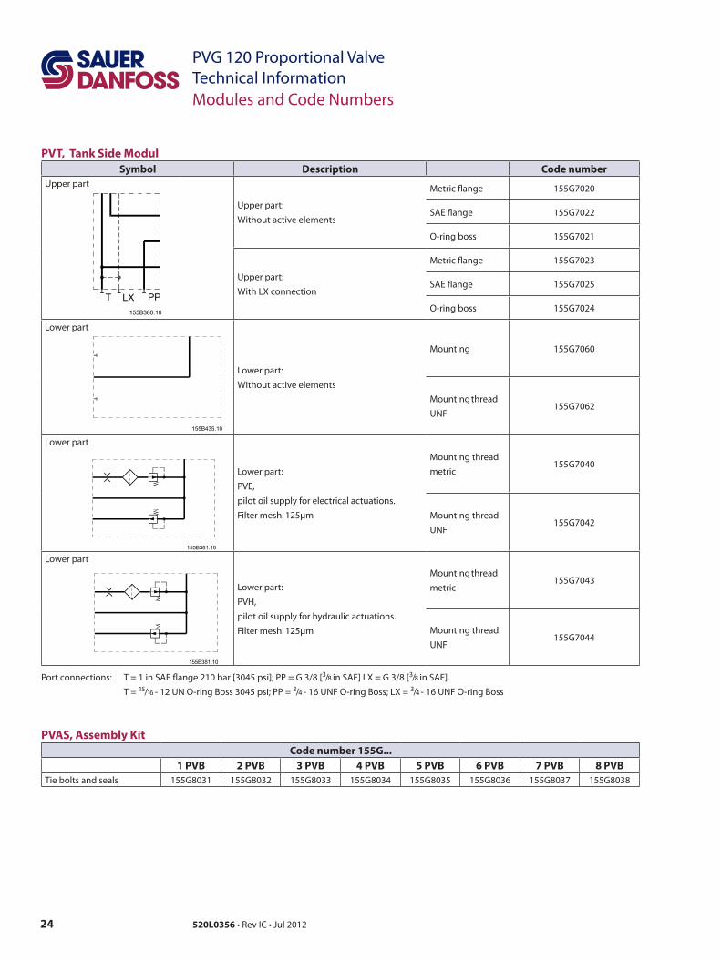
PVT, Tank Side ModulSymbol Description Code number
Upper part
Upper part:Without active elements
Metric flange 155G7020
SAE flange 155G7022
O-ring boss 155G7021
Upper part:With LX connection
Metric flange 155G7023
SAE flange 155G7025
O-ring boss 155G7024
Lower part
Lower part:Without active elements
Mounting 155G7060
Mounting thread
UNF155G7062
Lower part
Lower part:PVE, pilot oil supply for electrical actuations.
Filter mesh: 125µm
Mounting thread metric
155G7040
Mounting thread
UNF155G7042
Lower part
Lower part:PVH,
pilot oil supply for hydraulic actuations.
Filter mesh: 125µm
Mounting thread metric
155G7043
Mounting thread
UNF155G7044
Port connections: T = 1 in SAE flange 210 bar [3045 psi]; PP = G 3/8 [3/8 in SAE] LX = G 3/8 [3/8 in SAE]. T = 15/16 - 12 UN O-ring Boss 3045 psi; PP = 3/4 - 16 UNF O-ring Boss; LX = 3/4 - 16 UNF O-ring Boss
PVAS, Assembly KitCode number 155G...
1 PVB 2 PVB 3 PVB 4 PVB 5 PVB 6 PVB 7 PVB 8 PVBTie bolts and seals 155G8031 155G8032 155G8033 155G8034 155G8035 155G8036 155G8037 155G8038
Modules and Code Numbers
25520L0356 • Rev IC • Jul 2012
PVG 120 Proportional ValveTechnical Information
Modules for Oil Flow Exceeding 180 l/min [47.6 US gal/min]
Modules and Code Numbers
Pump with fixed displacement1. Ordering:
Order accessory module 155G6035, main spool D, and pump side modules 155G5027/155G5028/155G5029
2. Conversion: In open centre systems a max. oil flow exceeding 180 l/min [47.6 US gal/min] is achieved by changing the following parts in the pump side and basic modules:
– Open centre pump side modulea. Pressure adjustment spoolb. The springs behind the pressure adjustment spoolc. The plug behind the pressure adjustment spool
Parts from kit 155G5035 may be used. – Closed centre pump side module
A closed centre pump side module can be changed into an upgraded open centre pump side module by means of kit 155G5035.
– Basic moduled. Spring behind pressure compensator e. The plug behind the pressure compensator
Spring and plug with code number 155G6035 (PVBU, accessory module).
Pump with variable displacement1. Ordering: Order accessory module 155G6035 and main spool D.
2. Conversion: In closed centre systems a max. oil flow exceeding 180 l/min [47.6 US gal/min] can
be achieved by changing the following basic module parts: a) Spring behind pressure compensator b) The plug behind the pressure compensator The code number of the spring and plug is 155G6035 (PVBU, accessory module).
26 520L0356 • Rev IC • Jul 2012
PVG 120 Proportional ValveTechnical Information
General
PVP, Pump Side Module
Technical Characteristics
All characteristics and values in this Technical Information are typical measured results. For the hydraulic system a mineral based hydraulic oil with a viscosity of 21mm2/s [102 SUS] and a temperature of 50°C [122°F] was used.
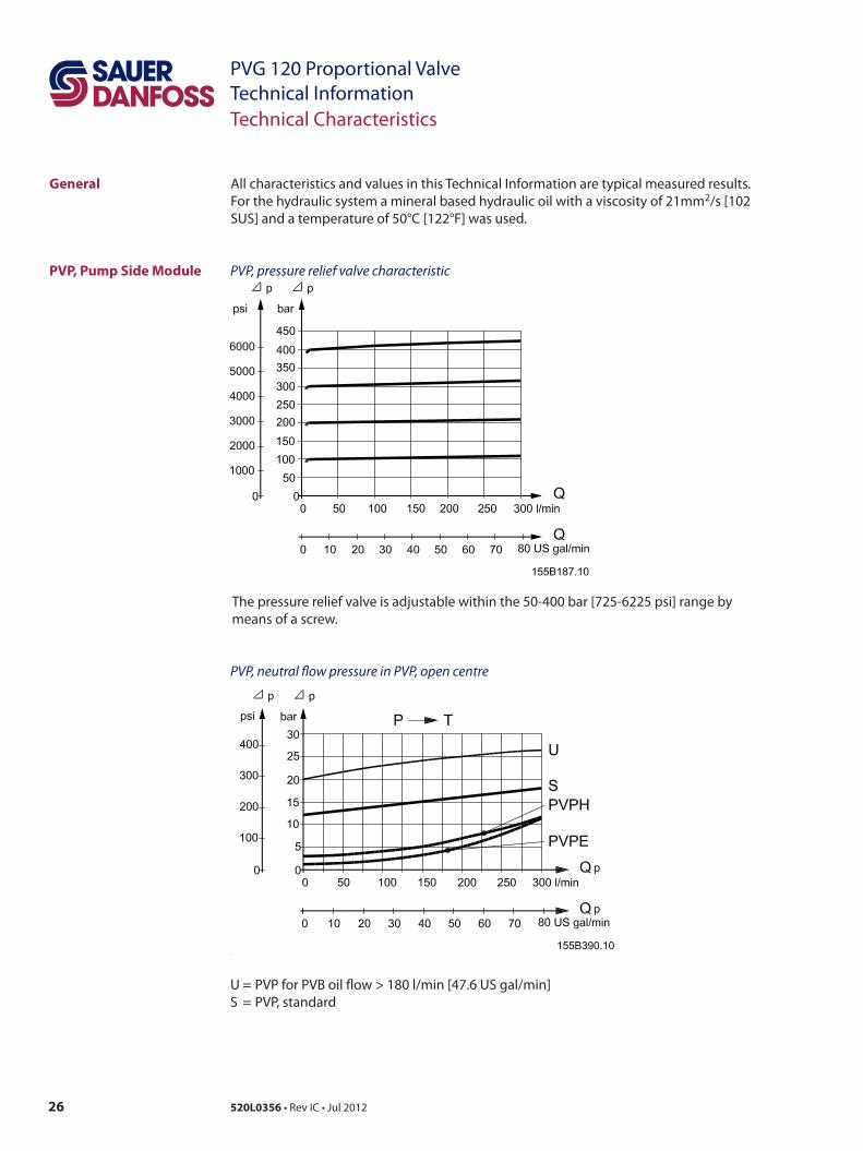
PVP, pressure relief valve characteristic
The pressure relief valve is adjustable within the 50-400 bar [725-6225 psi] range by means of a screw.
PVP, neutral flow pressure in PVP, open centre
U = PVP for PVB oil flow > 180 l/min [47.6 US gal/min]S = PVP, standard
27520L0356 • Rev IC • Jul 2012
PVG 120 Proportional ValveTechnical Information
PVB, Basic Module
Technical Characteristics
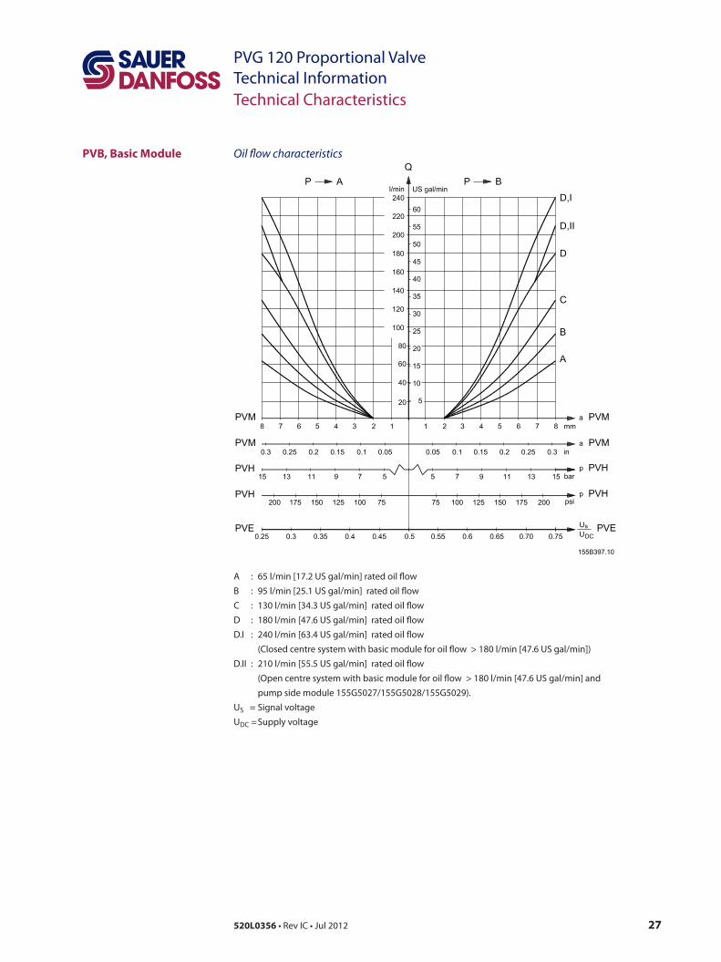
Oil flow characteristics
A : 65 l/min [17.2 US gal/min] rated oil flow B : 95 l/min [25.1 US gal/min] rated oil flow C : 130 l/min [34.3 US gal/min] rated oil flow D : 180 l/min [47.6 US gal/min] rated oil flow D.I : 240 l/min [63.4 US gal/min] rated oil flow (Closed centre system with basic module for oil flow > 180 l/min [47.6 US gal/min]) D.II : 210 l/min [55.5 US gal/min] rated oil flow (Open centre system with basic module for oil flow > 180 l/min [47.6 US gal/min] and pump side module 155G5027/155G5028/155G5029). US = Signal voltage UDC = Supply voltage
28 520L0356 • Rev IC • Jul 2012
PVG 120 Proportional ValveTechnical Information
PVB, Basic Module
Technical Characteristics
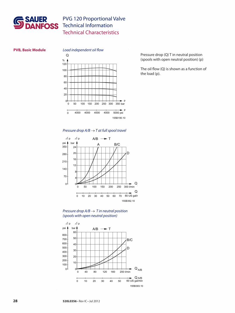
Load independent oil flowPressure drop (Q) T in neutral position (spools with open neutral position) (p)
The oil flow (Q) is shown as a function of the load (p).
Pressure drop A/B → T at full spool travel
Pressure drop A/B → T in neutral position (spools with open neutral position)
29520L0356 • Rev IC • Jul 2012
PVG 120 Proportional ValveTechnical Information
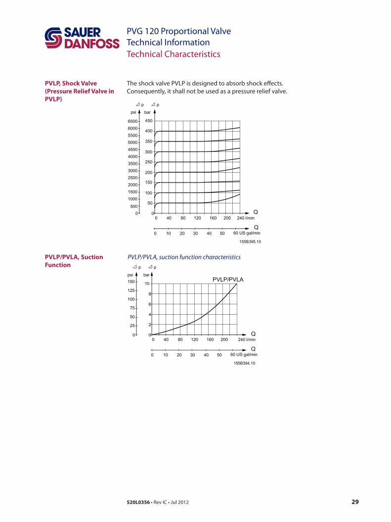
PVLP, Shock Valve (Pressure Relief Valve in PVLP)
PVLP/PVLA, Suction Function
Technical Characteristics
The shock valve PVLP is designed to absorb shock effects. Consequently, it shall not be used as a pressure relief valve.
PVLP/PVLA, suction function characteristics
30 520L0356 • Rev IC • Jul 2012
PVG 120 Proportional ValveTechnical Information
55.5[2.185]
T P
21.5[0.846]L42
[1.6
5] 120[
4.72
]14
7[5.
79]
220[
8.66
]
LL
21
185[
7.28
]14
7[5.
79]
95[3
.74]
68[2
.68]
10.5
[0.4
13]
38[1
.50]
52.4
[2.0
63] 50
.8
26.2[1.031]23.8[0.937]
27.8
66.5[2.618] 67[2.638] 73.5[2.893]36.5[1.437]
A A
BB
T P
DCJK
57.2
[2.2
52]
M
E
N F
H 33.5~165[6.50]
max.61[2.40]
69[2
.72]
37
44[1.73]
113.
5[4.
468]
28
G
105[4.13]
LX
T
33.5
PP
152[5.98]158[6.22]
PG 9 [on-o]PG 11 [prop.]DIN 43650
V310153.B
35.5
max. 262.5[10.335] 111[4.37]
25[0.98]
27[1.06]
15[0.59]
[1.4
6]
[1.398] [1.319] [1.319]
[1.10]
23.8[0.937]
[1.094]
38[1
.50]
[2.0
00]
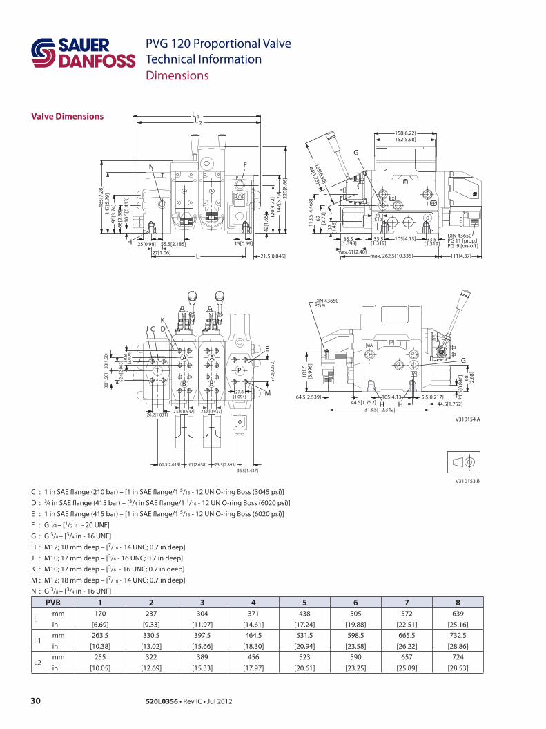
Valve Dimensions
Dimensions
C : 1 in SAE flange (210 bar) – [1 in SAE flange/1 5/16 - 12 UN O-ring Boss (3045 psi)] D : 3⁄4 in SAE flange (415 bar) – [3/4 in SAE flange/1 1/16 - 12 UN O-ring Boss (6020 psi)] E : 1 in SAE flange (415 bar) – [1 in SAE flange/1 5/16 - 12 UN O-ring Boss (6020 psi)] F : G 1⁄4 – [1/2 in - 20 UNF] G : G 3/8 – [3/4 in - 16 UNF] H : M12; 18 mm deep – [7/16 - 14 UNC; 0.7 in deep] J : M10; 17 mm deep – [3/8 - 16 UNC; 0.7 in deep] K : M10; 17 mm deep – [3/8 - 16 UNC; 0.7 in deep] M : M12; 18 mm deep – [7/16 - 14 UNC; 0.7 in deep] N : G 3/8 – [3/4 in - 16 UNF]
PVB 1 2 3 4 5 6 7 8
Lmm
in
170
[6.69]
237
[9.33]
304
[11.97]
371
[14.61]
438
[17.24]
505
[19.88]
572
[22.51]
639
[25.16]
L1mm
in
263.5
[10.38]
330.5
[13.02]
397.5
[15.66]
464.5
[18.30]
531.5
[20.94]
598.5
[23.58]
665.5
[26.22]
732.5
[28.86]
L2mm
in
255
[10.05]
322
[12.69]
389
[15.33]
456
[17.97]
523
[20.61]
590
[23.25]
657
[25.89]
724
[28.53]
64.5[2.539] 105[4.13] 5.5[0.217]
PMA
LS101.
5[3
.996
]
44.5[1.752]313.5[12.342]
44.5[1.752]
G
DIN 43650PG 9
68[2
.68]
21.5
[0.8
46]
HH
V310154.A
31520L0356 • Rev IC • Jul 2012
PVG 120 Proportional ValveTechnical Information
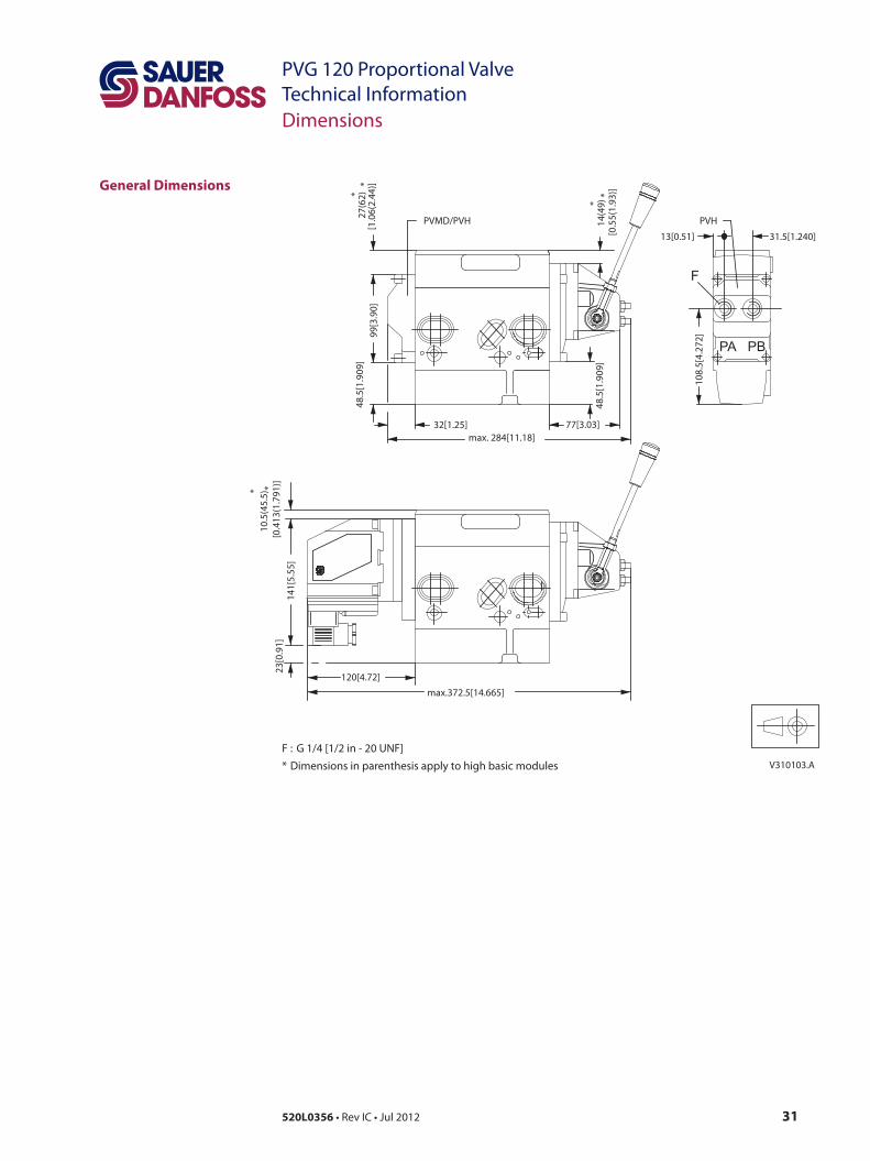
General Dimensions
Dimensions
31.5[1.240]
14(4
9)
32[1.25]
F
13[0.51]
108.
5[4.
272]
*
27(6
2)99
[3.9
0]
PVHPVMD/PVH
PBPA
*
120[4.72]
141[
5.55
]
max.372.5[14.665]
77[3.03]max. 284[11.18]
23[0
.91]
48.5
[1.9
09]
48.5
[1.9
09]
[1.0
6(2.
44)]*
[0.5
5(1.
93)]
*
V310103.A
* *
[0.4
13(1
.791
)]10
.5(4
5.5)
F : G 1/4 [1/2 in - 20 UNF] * Dimensions in parenthesis apply to high basic modules
32 520L0356 • Rev IC • Jul 2012
PVG 120 Proportional ValveTechnical InformationLever Positions
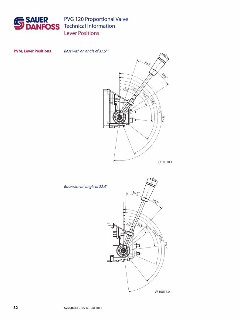
Base with an angle of 37.5°
37.5˚67.5˚
97.5˚ 127.5˚
157.5˚187.5˚
19.5˚
19.5˚
V310018.A
22.5˚ 52.5˚ 82.5˚ 112.5˚ 142.5˚ 172.5˚
19.5˚
19.5˚
V310014.A
PVM, Lever Positions
Base with an angle of 22.5°
33520L0356 • Rev IC • Jul 2012
PVG 120 Proportional ValveTechnical InformationSafety in Application
Building in Safety All makes and all types of control valves (incl. proportional valves) can fail. Thus the necessary protection against the serious consequences of function failure should always be built into the system. For each application an assessment should be made for the consequences of pressure failure and uncontrolled or blocked movements.
To determine the degree of protection that is required to be built into the application, system tools such an FMEA (Failure Mode and Effect Analysis) and Hazard and Risk Analysis can be used.
FMEA (Failure Mode and Effect Analysis) IEC EN 61508FMEA is a tool used for analyzing potential risks. This analytical technique is utilized to define, identify, and prioritize the elimination or reduction of known and/or potential failures from a given system before it is released for production.Please refer to IEC FMEA Standard 61508.
Hazard and Risk Analysis ISO 12100-1 / 14121This analysis is a tool used in new applications as it will indicate whether there are special safety considerations to be meet according to the machine directives EN 13849. Dependent on the determined levels conformety this analysis will detirmine if any extra requirements for the product design, development process, production process or maintenance, i.e. the complete product life cycle.
WWarningAll makes/brands and types of directional control valves – inclusive proportional valves – can fail and cause serious damage. It is therefore important to analyze all aspects of the application. Because the proportional valves are used in many different operation conditions and applications, the manufacturer of the application is alone responsible for making the final selection of the products – and assuring that all performance, safety and warning requirements of the application are met. The process of choosing the control system – and safety levels – is governed by the machine directives EN 13849 (Safety related requirements for control systems).
34 520L0356 • Rev IC • Jul 2012
PVG 120 Proportional ValveTechnical Information
SupplyControl
NeutralDetection
Signal Conditioning
FailureDetection
FaultMonitoring
PVE fault output
SignalConditioning
SupplyMain controller
Hydraulic deactivation
HMI / Joystick
ControlSignal
Emergency stop andMan present switch Motion detection sensor
PVE
Main control valve
Main power supply(battery)
Joystick neutral switch
P301 317
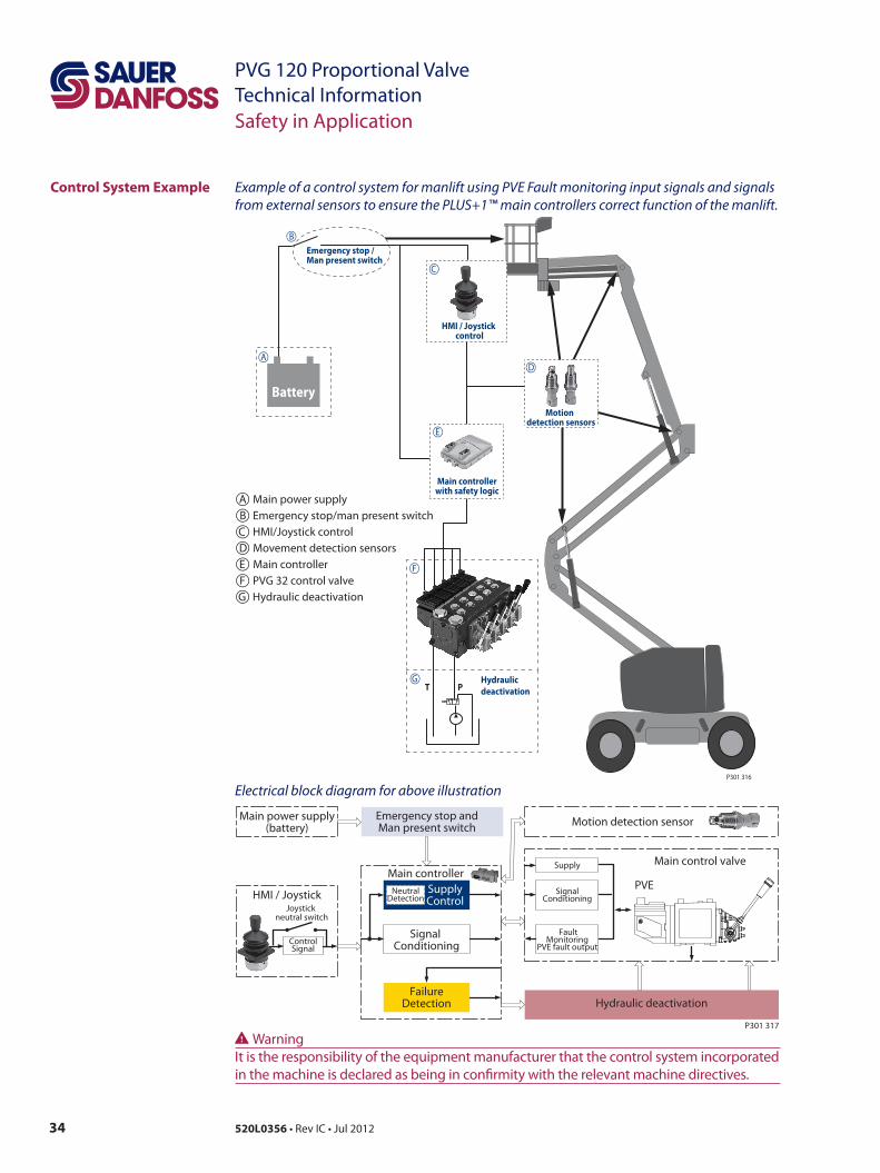
Control System Example
Safety in Application
Example of a control system for manlift using PVE Fault monitoring input signals and signals from external sensors to ensure the PLUS+1™ main controllers correct function of the manlift.
Electrical block diagram for above illustration
Emergency stop / Man present switch
T P
BatteryMotion
detection sensors
Main controller with safety logic
Hydraulic deactivation
HMI / Joystick control
A
B
C
D
E
F
G
P301 316
A Main power supplyB Emergency stop/man present switchC HMI/Joystick controlD Movement detection sensorsE Main controllerF PVG 32 control valveG Hydraulic deactivation
WWarningIt is the responsibility of the equipment manufacturer that the control system incorporated in the machine is declared as being in confirmity with the relevant machine directives.
35520L0356 • Rev IC • Jul 2012
PVG 120 Proportional ValveTechnical Information
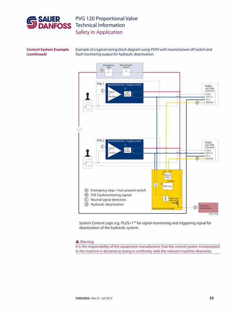
Example of a typical wiring block diagram using PVEH with neutral power off switch and fault monitoring output for hydraulic deactivation.
System Control Logic e.g. PLUS+1™ for signal monitoring and triggering signal for deactivation of the hydraulic system.
Fault detection output
high=onlow=o
Alarm logic
2)
Memory3)
E1 E2
Output
AN
D
OR
Neutral detection / Supply control
signal≠neutral
OFFDelay
1)
2(UDC2)3( )4(Error)
1(US)
PVEH with AMP connector
2(UDC2)3( )4(Error)
1(US)
PVEHwith AMP connector
Hydraulicdeactivation
Neutral detection / Supply control
signal≠neutral
OFFDelay
1)
PVE 1
PVE 2
Emergency stop
Man present switch
C
C
D
B
B
A
P301 318
Safety in Application
A Emergency stop / man present switchB PVE Faultmonitoring signalsC Neutral signal detection.D Hydraulic deactivation
Control System Example (continued)
WWarningIt is the responsibility of the equipment manufacturer that the control system incorporated in the machine is declared as being in confirmity with the relevant machine directives.
36 520L0356 • Rev IC • Jul 2012
PVG 120 Proportional ValveTechnical Information
Neutral detection / Supply control
signal≠neutral
OFFDelay
1)
Fault detection output
2(UDC2)3( )4(Error)
1(US)
2(DI-B)3( )
1(DI-A)
PVEH-DI AMP connector
4(UDC)
PVEH-DIAMP supply connector
2(UDC2)3( )4(Error)
1(US)
2(DI-B)3( )
1(DI-A)
PVEH-DI AMP connector
4(UDC)
PVEH-DIAMP supply connector
AN
D
Hydraulicdeactivation
high=onlow=o
Neutral detection / Supply control
signal≠neutral
OFFDelay
1)
PVE 1
PVE 2
Fault detection
DelayDILogic Memory
US
DI-ADI-B
2)4)3)
Output
Fault detection
DelayDILogic Memory
US
DI-ADI-B
2)4)3)
Output
OR
Emergency Stop
Man present switch
P301 319
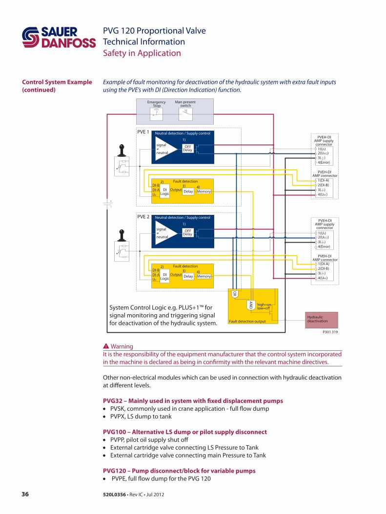
Example of fault monitoring for deactivation of the hydraulic system with extra fault inputs using the PVE’s with DI (Direction Indication) function.
System Control Logic e.g. PLUS+1™ for signal monitoring and triggering signal for deactivation of the hydraulic system.
Control System Example (continued)
Safety in Application
Other non-electrical modules which can be used in connection with hydraulic deactivation at different levels.
PVG32 – Mainly used in system with fixed displacement pumps• PVSK, commonly used in crane application - full flow dump• PVPX, LS dump to tank
PVG100 – Alternative LS dump or pilot supply disconnect• PVPP, pilot oil supply shut off• External cartridge valve connecting LS Pressure to Tank• External cartridge valve connecting main Pressure to Tank
PVG120 – Pump disconnect/block for variable pumps• PVPE, full flow dump for the PVG 120
WWarningIt is the responsibility of the equipment manufacturer that the control system incorporated in the machine is declared as being in confirmity with the relevant machine directives.

37520L0356 • Rev IC • Jul 2012
PVG 120 Proportional ValveTechnical InformationNotes
38 520L0356 • Rev IC • Jul 2012
PVG 120 Proportional ValveTechnical Information
Oil
Particle Content, Degree of Contamination
Other Operating Conditions
The main duty of the oil in a hydraulic system is to transfer energy; but it must also lubricate the moving parts in hydraulic components, protect them against corrosion, and transport dirt particles and heat out of the system. It is therefore important to choose the correct oil with the correct additives. This gives problem-free operation and long working life.
Mineral oilFor systems with PVG 120 valves Sauer-Danfoss recommends the use of mineral-based hydraulic oil containing additives: Type H-LP (DIN 51524) or HM (ISO 6743/4).
Non-flammable fluidsPhosphate-esters (HFDR fluids) can be used without special precautions. However, dynamic seals must be replaced with FPM (Viton) seals. Please contact the Sauer-Danfoss Sales Organisation if the PVG 120 valve is to be used with phosphate-esters.The following fluids should only be used according to agreement with the Sales Organisation for Sauer-Danfoss:• Water-glycol mixtures (HFC fluids)• Water-oil emulsions (HFB fluids)• Oil-water emulsions (HFAE fluids)
Biodegradable oilsPVG 120 valves can be used in systems using rape-seed oil. The use of rape-seed oil is conditional on• it complying with the demands on viscosity, temperature and filtration etc.
(see chapters below and technical data page 10).• the operating conditions being adapted to the recommendations of the oil supplier.
Before using other biodegradable fluids, please consult the Sauer-Danfoss Sales Organisation.
Oil filtration must prevent the particle content from exceeding an acceptable level, i.e. an acceptable degree of contamination.Maximum contamination for PVG 120 is 23/19/16 (see ISO 4406). Calibration in accordance with the ACFTD method.
In our experience a degree of contamination of 23/19/16 can be maintained by using a filter fineness as described in the next section.
39520L0356 • Rev IC • Jul 2012
PVG 120 Proportional ValveTechnical Information
Filtering
Conversion Factors
Other Operating Conditions
Effective filtration is the most important precondition in ensuring that a hydraulic system performs reliably and has a long working life. Filter manufacturers issue instructions and recommendations. It is advisable to follow them.
System filtersWhere demands for safety and reliability are very high a pressure filter with bypass and indicator is recommended. Experience shows that a 10 µm nominal filter (or finer) or a 20 µm absolute filter (or finer) is suitable.It is our experience that a return filter is adequate in a purely mechanically operated valve system.
The fineness of a pressure filter must be selected as described by the filter manufacturer so that a particle level of 23/19/16 is not exceeded. See “Particle content, degree of contami-nation”. The filter must be fitted with pressure gauge or dirt indicator to make it possible to check the condition of the filter.
In systems with differential cylinders or accumulators the return filter must be sized to suit the max. return oil flow. Pressure filters must be fitted to suit max. pump oil flow.
Internal filtersThe filters built into PVG 120 are not intended to filter the system but to protect important components against large particles.Such particles can appear in the system as a result of pump damage, hose fracture, use of quick-couplings, filter damage, starting up, contamination, etc.
The filter that protects the pilot supply in the tank side module has a mesh of 125 µm. It is obtainable as a spare part and is easy to replace.
The filter protecting the essential PVE parts has a mesh of 125 µm.
1 Nm = 885.1 lbf·in1 N = 22.48 lbf·in1 bar = 14.50 psi1 mm = 0.0394 in1 cm3 = 0.061 in3
1 l = 0.22 gallon, UK1 l = 0.264 gallon, US°F = 1.8 • °C + 32
40 520L0356 • Rev IC • Jul 2012
PVG 120 Proportional ValveTechnical Information
Order Form
Order Specification
An order form for Sauer-Danfoss PVG 120 hydraulic valve is shown on next page. The form can be obtained from the Sauer-Danfoss Sales Organisation.The module selection chart on the next page and the order form are divided into fields.
Each module has its own field:0: PVP, pump side modulesd: PVPD, PVPH and PVPE, accessory modules1-8: PVB, basic modulese: PVBS, main spoolsf: PVBP, PVBR, PVBU and PVBC, accessory modulesa: PVM, mechanical actuationc: PVMD, cover for mechanical operation PVH, cover for hydraulic operation PVEO and PVEH, electrical actuations b: PVLP, shock and suction valve PVLA, suction valve9: PVT, tank side module10: PVAS, assembly kit
Please state:• Code numbers of all modules required• Required setting (p) for pump side module• Required setting of LSA/B pressure relief valves, if accessory module PVBR is ordered.
41520L0356 • Rev IC • Jul 2012
PVG 120 Proportional ValveTechnical Information
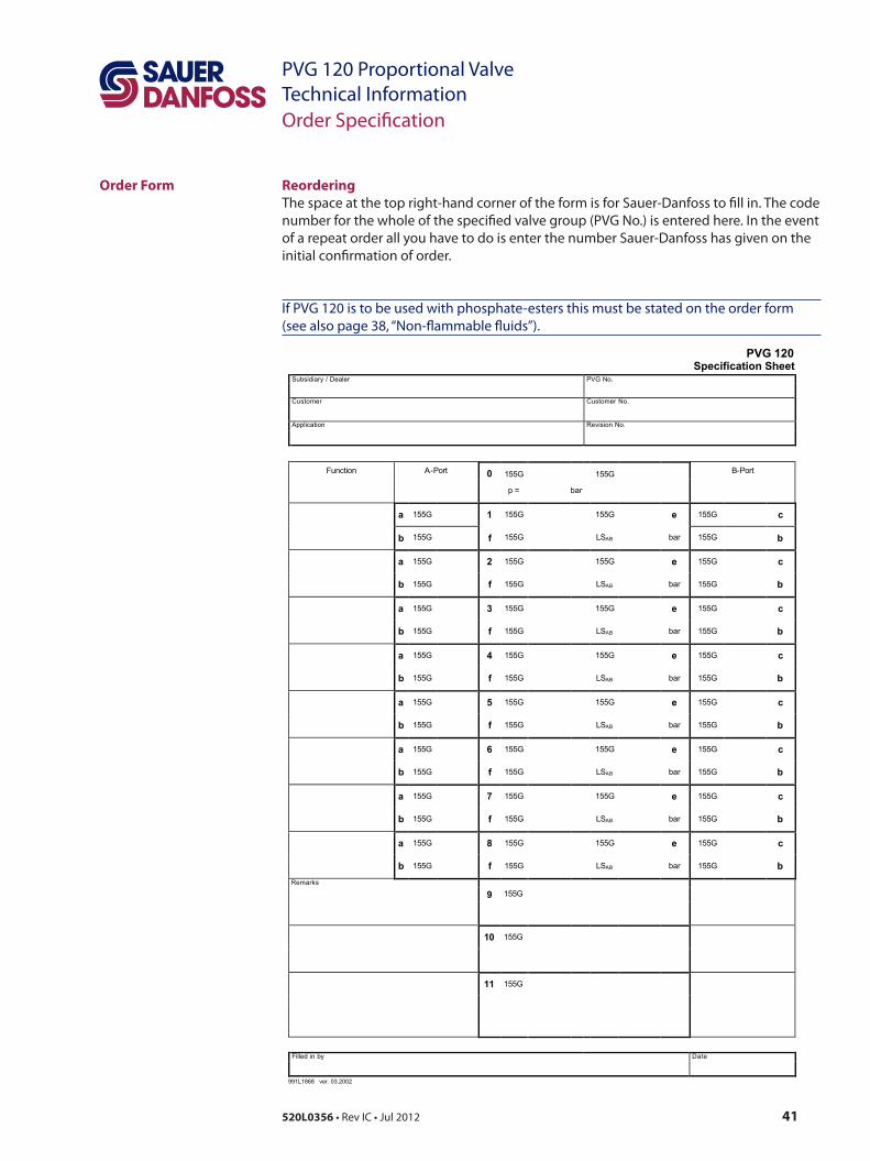
ReorderingThe space at the top right-hand corner of the form is for Sauer-Danfoss to fill in. The code number for the whole of the specified valve group (PVG No.) is entered here. In the event of a repeat order all you have to do is enter the number Sauer-Danfoss has given on the initial confirmation of order.
If PVG 120 is to be used with phosphate-esters this must be stated on the order form (see also page 38, “Non-flammable fluids”).
Order Form
Order Specification
PVG 120 Specification Sheet
Subsidiary / Dealer PVG No.
Customer Customer No.
Application Revision No.
Function A-Port 0 155G 155G B-Port
p = bar
a 155G 1 155G 155G e 155G c
b 155G f 155G LSAB bar 155G b
a 155G 2 155G 155G e 155G c
b 155G f 155G LSAB bar 155G b
a 155G 3 155G 155G e 155G c
b 155G f 155G LSAB bar 155G b
a 155G 4 155G 155G e 155G c
b 155G f 155G LSAB bar 155G b
a 155G 5 155G 155G e 155G c
b 155G f 155G LSAB bar 155G b
a 155G 6 155G 155G e 155G c
b 155G f 155G LSAB bar 155G b
a 155G 7 155G 155G e 155G c
b 155G f 155G LSAB bar 155G b
a 155G 8 155G 155G e 155G c
b 155G f 155G LSAB bar 155G bRemarks
9 155G
10 155G
11 155G
Filled in by Date
991L1868 ver. 03.2002
42 520L0356 • Rev IC • Jul 2012
PVG 120 Proportional ValveTechnical Information
P
LS
P
T
fe
a
0
1-8
d
10 9
11c
b
V310173.A
Module Selection Chart
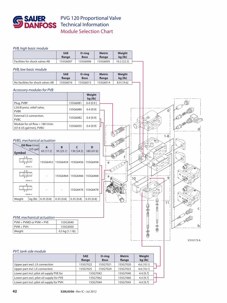
PVB, low basic moduleSAE
flangeO-ring
BossMetric flange
Weightkg [lb]
No facilities for shock valves AB 155G6016 155G6015 155G6014 8.9 [19.6]
Accessory modules for PVBWeightkg [lb]
Plug, PVBP 155G6081 0.4 [0.9 ]LSA/B press. relief valve, PVBR
155G6080 0.4 [0.9]
External LS connection, PVBC
155G6082 0.4 [0.9]
Module for oil flow > 180 l/min [47.6 US gal/min], PVBU
155G6035 0.4 [0.9]
PVT, tank side moduleSAE
flangeO-ring
BossMetricflange
Weightkg [lb]
Upper part excl. LX connection 155G7022 155G7021 155G7020 4.6 [10.1]Upper part incl. LX connection 155G7025 155G7024 155G7023 4.6 [10.1]Lower part incl. pilot oil supply PVE for 155G7042 155G7040 4.4 [9.7]Lower part excl. pilot oil supply for PVE 155G7062 155G7060 4.4 [9.7]Lower part incl. pilot oil supply for PVH 155G7044 155G7043 4.4 [9.7]
PVBS, mechanical actuationOil flow l/min
[US gal]Symbol
A65 [17.2]
B95 [25.1]
C130 [34.3]
D180 [47.6]
155G6452 155G6454 155G6456 155G6458
- 155G6464 155G6466 155G6468
- - 155G6476 155G6478
Weight kg [lb] 0.35 [0.8] 0.35 [0.8] 0.35 [0.8] 0.35 [0.8]
PVM, mechanical actuationPVM + PVMD or PVM + PVE 155G3040PVM + PVH 155G3050Weight 0.5 kg [1.1 lb]
PVB, high basic moduleSAE
flangeO-ring
BossMetric flange
Weightkg [lb]
Facilities for shock valves AB 155G6007 155G6006 155G6005 10.2 [22.5]
43520L0356 • Rev IC • Jul 2012
PVG 120 Proportional ValveTechnical InformationModule Selection Chart
P
LS
P
T
fe
a
0
1-8
d
10 9
11c
b
V310173.A
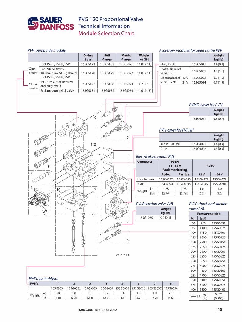
Electrical actuation PVEConnector PVEH
11 - 32 VFault monitoring
PVEO
Active Passive 12 V 24 VHirschmann 155G4092 155G4093 155G4272 155G4274AMP 155G4094 155G4095 155G4282 155G4284
Weightkg 1.25 1.25 1.0 1.0[lb] [2.76] [2.76] [2.2] [2.2]
PVLP, shock and suction valve A/B
Pressure setting bar [psi]50 725 155G005075 1100 155G0075
100 1450 155G0100125 1800 155G0125150 2200 155G0150175 2550 155G0175200 2900 155G0200225 3250 155G0225250 3650 155G0250275 4000 155G0275300 4350 155G0300325 4700 155G0325350 5100 155G0350375 5400 155G0375400 5800 155G0400
Weightkg[lb]
0.175[0.386]
PVLA suction valve A/BWeightkg [lb]
155G1065 0.2 [0.4]
PVAS, assembly kitPVB’s 1 2 3 4 5 6 7 8
155G8031 155G8032 155G8033 155G8034 155G8035 155G8036 155G8037 155G8038
Weightkg 0.8 1.0 1.1 1.2 1.4 1.7 1.9 2.1[lb] [1.8] [2.2] [2.4] [2.6] [3.1] [3.7] [4.2] [4.6]
PVH, cover for PVRHHWeightkg [lb]
1/2 in - 20 UNF 155G4021 0.4 [0.9]G 1/4 155G4022 0.4 [0.9]
PVMD, cover for PVMWeightkg [lb]
155G4061 0.3 [0.7]
PVP, pump side moduleO-ring
BossSAE
flangeMetric flange
Weightkg [lb]
Open centre
Excl. PVPD, PVPH, PVPE 155G5023 155G5037 155G5021 10.0 [22.1]For PVB-oil flow > 180 l/min [47.6 US gal/min]Excl. PVPD, PVPH, PVPE
155G5028 155G5029 155G5027 10.0 [22.1]
Closed centre
Incl. pressure relief valve and plug PVPD
155G5022 155G5038 155G5020 10.2 [22.5]
Excl. pressure relief valve 155G5031 155G5032 155G5030 11.0 [24.3]
Accessory modules for open centre PVPWeightkg [lb]
Plug, PVPD 155G5041 0.4 [0.9]Hydraulic relief valve, PVH
155G5061 0.5 [1.1]
Electrical relief valve, PVPE
12 V 155G5052 0.7 [1.5]24 V 155G5054 0.7 [1.5]
Local address:
Sauer-Danfoss GmbH & Co. OHGPostfach 2460, D-24531 NeumünsterKrokamp 35, D-24539 Neumünster, GermanyPhone: +49 4321 871 0Fax: +49 4321 871 122
Sauer-Danfoss ApSDK-6430 Nordborg, DenmarkPhone: +45 7488 4444Fax: +45 7488 4400
Sauer-Danfoss is a global manufacturer and supplier of high-quality hydraulic and electronic components. We specialize in providing state-of-the-art technology and solutions that excel in the harsh operating conditions of the mobile o -highway market. Building on our extensive applications expertise, we work closely with our customers to ensure exceptional performance for a broad range of o -highway vehicles.
We help OEMs around the world speed up system development, reduce costs and bring vehicles to market faster. Sauer-Danfoss – Your Strongest Partner in Mobile Hydraulics.
Go to www.sauer-danfoss.com for further product information.
Wherever o -highway vehicles are at work, so is Sauer-Danfoss.
We o er expert worldwide support for our customers, ensuring the best possible solutions for outstanding performance. And with an extensive network of Global Service Partners, we also provide comprehensive global service for all of our components.
Please contact the Sauer-Danfoss representative nearest you.
Products we o er:
• Bent Axis Motors
• Closed Circuit Axial Piston Pumps and Motors
• Displays
• Electrohydraulic Power Steering
• Electrohydraulics
• Hydraulic Power Steering
• Integrated Systems
• Joysticks and Control Handles
• Microcontrollers and Software
• Open Circuit Axial Piston Pumps
• Orbital Motors
• PLUS+1™ GUIDE
• Proportional Valves
• Sensors
• Steering
• Transit Mixer Drives
Members of the Sauer-Danfoss Group:
Comatrolwww.comatrol.com
Schwarzmüller-Inverterwww.schwarzmueller-inverter.com
Turolla www.turollaocg.com
Valmovawww.valmova.com
Hydro-Gear www.hydro-gear.com
Sauer-Danfoss-Daikinwww.sauer-danfoss-daikin.com
Sauer-Danfoss (US) Company2800 East 13th StreetAmes, IA 50010, USAPhone: +1 515 239 6000Fax: +1 515 239 6618
Sauer-Danfoss-Daikin LTD.Shin-Osaka TERASAKI 3rd Bldg. 6F1-5-28 Nishimiyahara, Yodogawa-kuOsaka 532-0004, JapanPhone: +81 6 6395 6066Fax: +81 6 6395 8585
w w w . s a u e r - d a n f o s s . c o m520L0356 • Rev IC • Jul 2012