Embed Size (px)
Citation preview

PVG 32Proportional Valves
Specifications
PVG 32
Specification Sheet
PHYD-PV
G32-3
Subsidiary/Dealer
PVG No.
Customer
Customer No.
Application
Revision No.
0157B
157B
Function
A-Port p =
bar157B
B-Port
a157B
1
157B
157B
13157B
c
b157B
LSA
barLSB
bar
157B b
a157B
2
157B
157B
13157B
c
b157B
LSA
barLSB
bar
157B b
a157B
3
157B
157B
13157B
c
b157B
LSA
barLSB
bar
157B b
a157B
4
157B
157B
13157B
c
b157B
LSA
barLSB
bar
157B b
a157B
5
157B
157B
13157B
c
b157B
LSA
barLSB
bar
157B b
a157B
6
157B
157B
13157B
c
b157B
LSA
barLSB
bar
157B b
a157B
7
157B
157B
13157B
c
b157B
LSA
barLSB
bar
157B b
a157B
8
157B
157B
13157B
c
b157B
LSA
barLSB
bar
157B b
a157B
9
157B
157B
13157B
c
b157B
LSA
barLSB
bar
157B b
a157B
10
157B
157B
13157B
c
b157B
LSA
barLSB
bar
157B b
11157B
12157B
Remarks
Filled in by
Date
PVG 32Specification Sheet
PHYD-PVG32-3
Subsidiary/Dealer PVG No.
Customer
Customer No.
Application
Revision No.
0 157B 157B
FunctionA-Port
p = bar 157B
B-Port
a 157B 1 157B 157B 13 157B c
b 157B LSA bar LSB bar 157B b
a 157B 2 157B 157B 13 157B c
b 157B LSA bar LSB bar 157B b
a 157B 3 157B 157B 13 157B c
b 157B LSA bar LSB bar 157B b
a 157B 4 157B 157B 13 157B c
b 157B LSA bar LSB bar 157B b
a 157B 5 157B 157B 13 157B c
b 157B LSA bar LSB bar 157B b
a 157B 6 157B 157B 13 157B c
b 157B LSA bar LSB bar 157B b
a 157B 7 157B 157B 13 157B c
b 157B LSA bar LSB bar 157B b
a 157B 8 157B 157B 13 157B c
b 157B LSA bar LSB bar 157B b
a 157B 9 157B 157B 13 157B c
b 157B LSA bar LSB bar 157B b
a 157B 10 157B 157B 13 157B c
b 157B LSA bar LSB bar 157B b
11 157B
12 157B Remarks
Filled in by
Date
PVG 32Specification Sheet
PHYD-PVG32-3
Subsidiary/Dealer
PVG No.
Customer
Customer No.
Application
Revision No.
0157B
157B
Function
A-Port
p = bar
157B B-Port
a157B 1
157B 157B
13157B
c
b157B
LSA bar
LSB bar
157B b
a157B 2
157B 157B
13157B
c
b157B
LSA bar
LSB bar
157B b
a157B 3
157B 157B
13157B
c
b157B
LSA bar
LSB bar
157B b
a157B 4
157B 157B
13157B
c
b157B
LSA bar
LSB bar
157B b
a157B 5
157B 157B
13157B
c
b157B
LSA bar
LSB bar
157B b
a157B 6
157B 157B
13157B
c
b157B
LSA bar
LSB bar
157B b
a157B 7
157B 157B
13157B
c
b157B
LSA bar
LSB bar
157B b
a157B 8
157B 157B
13157B
c
b157B
LSA bar
LSB bar
157B b
a157B 9
157B 157B
13157B
c
b157B
LSA bar
LSB bar
157B b
a157B 10
157B 157B
13157B
c
b157B
LSA bar
LSB bar
157B b
11157B 12
157B
Remarks
Filled in by
Date

2 520L0515 • Rev JB • Dec 2010
PVG 32 Proportional ValveSpecification
© 2010 Sauer-Danfoss. All rights reserved.
Sauer-Danfoss accepts no responsibility for possible errors in catalogs, brochures and other printed material. Sauer -Danfoss reserves the right to alter its products without prior notice. This also applies to products already ordered provided that such alterations can be made without affecting agreed specifications. All trademarks in this material are properties of their respective owners. Sauer-Danfoss, the Sauer-Danfoss logotype, the Sauer-Danfoss S-icon, PLUS+1™, What really matters is inside® and Know-How in Motion™ are trademarks of the Sauer-Danfoss Group.
Order Specification
Order Specification PVG 32Specification Sheet
PHYD-PVG32-3
Subsidiary/Dealer PVG No.
Customer Customer No.
Application Revision No.
0 157B 157B Function A-Port
p = bar 157B
B-Port
a 157B 1 157B 157B 13 157B c
b 157B LSA bar LSB bar 157B b
a 157B 2 157B 157B 13 157B c
b 157B LSA bar LSB bar 157B b
a 157B 3 157B 157B 13 157B c
b 157B LSA bar LSB bar 157B b
a 157B 4 157B 157B 13 157B c
b 157B LSA bar LSB bar 157B b
a 157B 5 157B 157B 13 157B c
b 157B LSA bar LSB bar 157B b
a 157B 6 157B 157B 13 157B c
b 157B LSA bar LSB bar 157B b
a 157B 7 157B 157B 13 157B c
b 157B LSA bar LSB bar 157B b
a 157B 8 157B 157B 13 157B c
b 157B LSA bar LSB bar 157B b
a 157B 9 157B 157B 13 157B c
b 157B LSA bar LSB bar 157B b
a 157B 10 157B 157B 13 157B c
b 157B LSA bar LSB bar 157B b
11 157B
12 157B
Remarks
Filled in by
Date

3520L0515 • Rev JB • Dec 2010
PVG 32 Proportional ValveSpecification
Both the module selection chart on the previous pages and the order form are divided into fields 0, 1-10, 11, 12, 13, a, b, and c.
Each module has its own field:0: - Pump side module PVP - Plug for external pilot oil supply PVPC - Electrical LS unloading valve PVPX1-10: Basic valves PVB13: Main spool PVBS a: Mechanical actuator PVM (or PVE when option mounted)c: - Cover for mechanical actuation PVMD - Cover for hydraulic actuation PVH - Electrical actuators PVE (or PVE when option mounted)b: - Shock and suction valve PVLP - Suction valve PVLA 11: End plate PVS/PVSI 12: Assembly kit PVAS
Please state- Code numbers of all modules required- Required setting (P) for pump side module- Required setting of LSA/B pressure limiting valves, see pressure setting guidance
below.
Standard and option assemblyThe PVG 32 valve group is assembled the way the module selection chart shows if the code number for PVM is written in field a, and the code number for PVMD, PVE or PVH in field c.The valve group is assembled so that the mechanical actuator is mounted on the opposite end of the basic module, if the code number for PVM is written in field c of the order form and the code numbers for PVMD, PVE or PVH in field a.
Pressure setting limitsThe maximum setting pressure for the pressure limiting valves LSA or LSB depends on the chosen pressure setting for shock valve PVLP. The maximum values recommended to avoid interaction can be read in the following table.The figures in the table have been calculated according to the following expressions:- PVLP ≤150 bar: LSA/B ≤ 0.8 × PPVLP
- PVLP >150 bar: PPVLP - LSA/B ≥ 30 bar.
Max. pressure setting of LSA and LSB valves relative to PVLP shock valve
Order Specification
Order Specification
Setting pressure for PVLP
bar 32 50 63 80 100 125 140 150 160 175 190 210 230 240 250 265 280 300 320 350 380 400
[psi] 460 725 914 1160 1450 1813 2031 2175 2320 2838 2755 3045 3335 3480 3625 3843 4061 4351 4641 5075 5510 5800
Max. setting pressure for LSA/B
bar - 40 50 64 80 100 112 120 130 145 160 180 200 210 220 235 250 270 290 320 350 370
[psi] - 580 720 930 1160 1450 1625 1740 1885 2100 2320 2610 2900 3045 3190 3408 3625 3915 4205 4641 5075 5366
Min. setting pressurefor LSA/B
bar 30
[psi] 435
4 520L0515 • Rev JB • Dec 2010
PVG 32 Proportional ValveSpecification
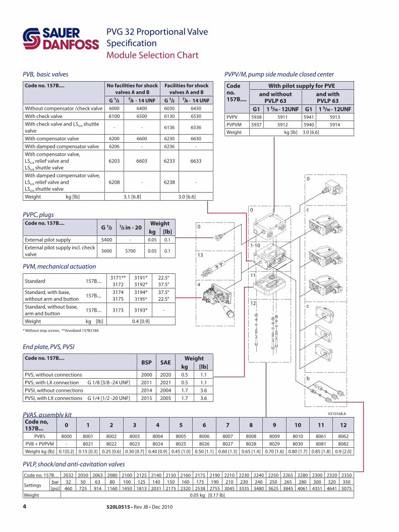
End plate, PVS, PVSI
Code no. 157B....BSP SAE
Weightkg [lb]
PVS, without connections 2000 2020 0.5 1.1PVS, with LX connection G 1/8 [3/8 -24 UNF] 2011 2021 0.5 1.1PVSI, without connections 2014 2004 1.7 3.6PVSI, with LX connections G 1/4 [1/2 -20 UNF] 2015 2005 1.7 3.6
V310168.A
0
13
a
0
11
12
0
c
c
b
1-10
Module Selection Chart
PVAS, assembly kitCode no, 157B... 0 1 2 3 4 5 6 7 8 9 10 11 12
PVB’s 8000 8001 8002 8003 8004 8005 8006 8007 8008 8009 8010 8061 8062
PVB + PVPVM - 8021 8022 8023 8024 8025 8026 8027 8028 8029 8030 8081 8082
Weight kg [lb] 0.1[0.2] 0.15 [0.3] 0.25 [0.6] 0.30 [0.7] 0.40 [0.9] 0.45 [1.0] 0.50 [1.1] 0.60 [1.3] 0.65 [1.4] 0.70 [1.6] 0.80 [1.7] 0.85 [1.8] 0.9 [2.0]
PVPV/M, pump side module closed center
Code no. 157B....
With pilot supply for PVEand without
PVLP 63and with PVLP 63
G1 1 5/16 - 12UNF G1 1 5/16 - 12UNFPVPV 5938 5911 5941 5913
PVPVM 5937 5912 5940 5914
Weight kg [lb] 3.0 [6.6]
PVLP, shock/and anti-cavitation valves
Code no. 157B… 2032 2050 2063 2080 2100 2125 2140 2150 2160 2175 2190 2210 2230 2240 2250 2265 2280 2300 2320 2350
Settingsbar 32 50 63 80 100 125 140 150 160 175 190 210 230 240 250 265 280 300 320 350[psi] 460 725 914 1160 1450 1813 2031 2175 2320 2538 2755 3045 3335 3480 3625 3845 4061 4351 4641 5075
Weight 0.05 kg [0.17 lb]
PVB, basic valves
Code no. 157B.... No facilities for shock valves A and B
Facilities for shock valves A and B
G 1/2 7/8 - 14 UNF G 1/2 7/8 - 14 UNFWithout compensator /check valve 6000 6400 6030 6430
With check valve 6100 6500 6130 6530
With check valve and LSA/B shuttle valve
- - 6136 6536
With compensator valve 6200 6600 6230 6630
With damped compensator valve 6206 - 6236 -
With compensator valve, LSA/B relief valve and LSA/B shuttle valve
6203 6603 6233 6633
With damped compensator valve, LSA/B relief valve and LSA/B shuttle valve
6208 - 6238 -
Weight kg [lb] 3.1 [6.8] 3.0 [6.6]
PVPC, plugsCode no. 157B....
G 1/2 1/2 in - 20Weight
kg [lb]External pilot supply 5400 - 0.05 0.1
External pilot supply incl. check valve
5600 5700 0.05 0.1
PVM, mechanical actuation
Standard 157B....3171**3172
3191*3192*
22.5°37.5°
Standard, with base, without arm and button
157B....31743175
3194*3195*
37.5°22.5°
Standard, without base, arm and button
157B.... 3173 3193* -
Weight kg [lb] 0.4 [0.9]
* Without stop screws. **Anodized 157B3184

5520L0515 • Rev JB • Dec 2010
PVG 32 Proportional ValveSpecificationModule Selection Chart
PVMD, PVH, PVMR, PVMF covers
Code no. 157B....Code No.
Weightkg [lb]
PVMR (frict. detent) 0004 0.3 0.6PVMF (mech. float position) 0005 0.3 0.6Cover for PVM 0001 0.1 0.2Hydraulic actuation PVH9/16 - 18 UNF
0007 0.9 2.0
Hydraulic actuation PVH G 1/4
0008 0.2 0.4
V310168.A
0
13
a
0
11
12
0
c
c
b
1-10
PVP, pump side module
Code no. 157B.... Without pilot supply With pilot supplyfor PVE for PVE
with facilit. for PVPX
for PVE for PVE and facilit. for
PVPX
for PVE and pilot oil
pressure take-off
for PVH and pilot
oil pressure take-off
Open centre
P = G 1/2, T = G 3/4 5000 - 5010 5012 - -P = 7/8 in - 14, T = 1 1/16 in - 12 5200 - 5210 5212 - -P = G 3/4, T = G 3/4 5100 5102 5110 5112 5180 5190P = 1 1/16 in - 12, T = 1 1/16 in - 12 5300 - 5310 5312 5380 5390
Closed centre
P = G 1/2 , T = G 3/4, 5001 - 5011 5013 - -
P = 7/8 in - 14, T = 1 1/16 in - 12 5201 - 5211 5213 - -P = G 3/4, T = G 3/4, 5101 5103 5111 5113 5181 5191P = 1 1/16 in - 12, T = 1 1/16 in - 12 5301 - 5311 5313 5381 5391
Weight kg [lb] 3.0 [6.6] 3.0 [6.6] 3.0 [6.6] 3.0 [6.6] 3.0 [6.6] 3.0 [6.6]
PVPX, electrical LS pressure relief valvesCode no. 157B.... Code
No.Weight
kg [lb]
Normally open12 V 4236 0.3 0.724 V 4238 0.3 0.7
Normally closed12 V 4246 0.3 0.724 V 4248 0.3 0.7
Normally open withmanual override
12 V 4256 0.3 0.724 V 4258 0.3 0.726 V 4260 0.3 0.7
Plug 5601 0.06 0.13
PVE, electrical actuationCode no. 157B.... Code No. Weight
Hir. AMP Deut. kg [lb]
PVEO, on-off12 V 4216 4901 4291 0.6 [1.3]
24 V 4228 4902 4292 0.6 [1.3]
PVEO-R, on/off12 V 4217 4903 - 0.6 [1.3]
24 V 4229 4904 - 0.6 [1.3]
PVEM, prop. medium – Standard
12 V 4116 - - 0.9 [2.0]
24 V 4128 - - 0.9 [2.0]
PVEM, prop. medium – Float -> B
12 V 4416 - - 1.0 [2.2]
24 V 4428 - - 1.0 [2.2]
PVEA, active fault mon.PVEA, passive fault mon.
--
47344735
4792-
0.9 [2.0]0.9 [2.0]
PVEA-DI, active fault mon.PVEA-DI, passive fault mon.
--
47364737
4796-
0.9 [2.0]0.9 [2.0]
PVEH active fault mon.PVEH passive fault mon.
40324033
40344035
40924093
1.0 [2.2]1.0 [2.2]
PVEH float -> B, act. faultPVEH float -> A, act. fault
4332-
-4338
4392-
1.0 [2.2]1.0 [2.2]
PVEH- DI active fault mon. PVEH - DI passive fault mon.
--
40364037
4096-
1.0 [2.2]1.0 [2.2]
PVES, active fault mon. PVES, passive fault mon.
48324833
48344835
4892-
1.0 [2.2]1.0 [2.2]
PVLA, anti-cavitation valveCode no. 157B.... Code No. Weight
kg [lb]Plug A or B 2002 0.04 0.09Valve A or B 2001 0.05 0.1
6 520L0515 • Rev JB • Dec 2010
PVG 32 Proportional ValveSpecification
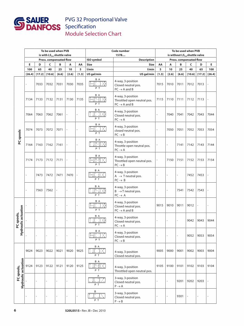
To be used when PVB is with LSA/B shuttle valve
Code number157B....
To be used when PVB is without LSA/B shuttle valve
Press. compensated flow ISO symbol Description Press. compensated flow
E D C B A AA Size Size AA A B C D E
100 65 40 25 10 5 l/min l/min 5 10 25 40 65 100
[26.4] [17.2] [10.6] [6.6] [2.6] [1.3] US gal/min US gal/min [1.3] [2.6] [6.6] [10.6] [17.2] [26.4]
PC s
pool
s
- 7033 7032 7031 7030 70354-way, 3-position Closed neutral pos. PC → A and B
7015 7010 7011 7012 7013 -
7134 7133 7132 7131 7130 71354-way, 3-position Throttled open neutral pos. PC → A and B
7115 7110 7111 7112 7113 -
7064 7063 7062 7061 - -4-way, 3-position Closed neutral pos. PC → A
- 7040 7041 7042 7043 7044
7074 7073 7072 7071 - -4-way, 3-position closed neutral pos.PC → B
- 7050 7051 7052 7053 7054
7164 7163 7162 7161 - -4-way, 3-position Throttle open neutral pos.PC → A
- - 7141 7142 7143 7144
7174 7173 7172 7171 - -4-way, 3-position Throttled open neutral pos. PC → B
- 7150 7151 7152 7153 7154
- 7473 7472 7471 7470 -4-way, 3-positionA → T neutral pos.PC → B
- - - 7452 7453 -
- 7563 7562 - - -4-way, 3-position B → T neutral pos. PC → A
- - 7541 7542 7543 -
PC s
pool
s,
Hyd
raul
ic a
ctua
tion
- - - - - -4-way, 3-position Closed neutral pos.PC → A and B
9015 9010 9011 9012 - -
- - - - - -4-way, 3-position Closed neutral pos.PC → A
- - - 9042 9043 9044
- - - - - -4-way, 3-positionClosed neutral pos. PC → B
- - - 9052 9053 9054
FC s
pool
s,
Hyd
raul
ic a
ctua
tion
9024 9023 9022 9021 9020 9025 4-way, 3-position Closed neutral pos.
9005 9000 9001 9002 9003 9004
9124 9123 9122 9121 9120 9125 4-way, 3-position Throttled open neutral pos.
9105 9100 9101 9102 9103 9104
- - - - - -3-way, 3-positionClosed neutral pos.P → A
- - 9201 9202 9203 -
- - - - - -3-way, 3-position Closed neutral pos. P → B
- - 9301 - - -
Module Selection Chart
7520L0515 • Rev JB • Dec 2010
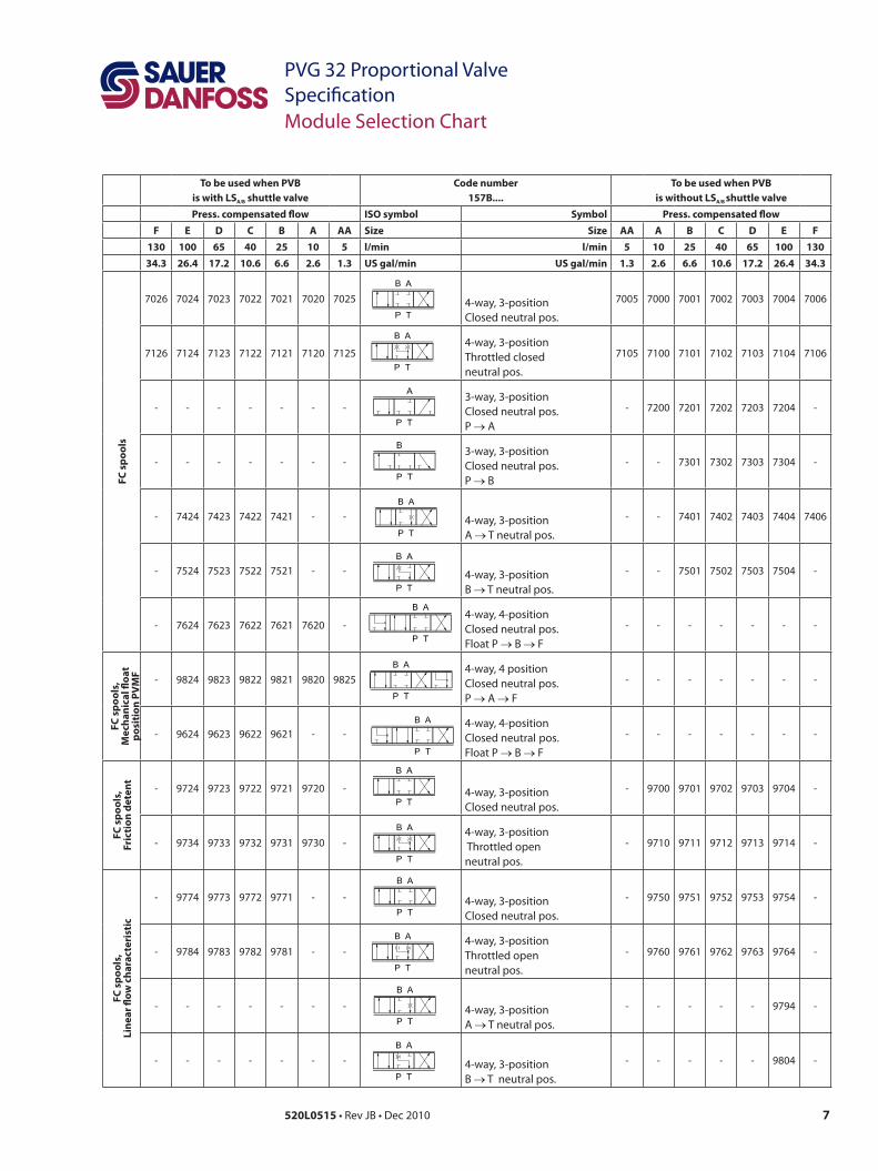
PVG 32 Proportional ValveSpecificationModule Selection Chart
To be used when PVB is with LSA/B shuttle valve
Code number157B....
To be used when PVB is without LSA/B shuttle valve
Press. compensated flow ISO symbol Symbol Press. compensated flowF E D C B A AA Size Size AA A B C D E F
130 100 65 40 25 10 5 l/min l/min 5 10 25 40 65 100 13034.3 26.4 17.2 10.6 6.6 2.6 1.3 US gal/min US gal/min 1.3 2.6 6.6 10.6 17.2 26.4 34.3
FC s
pool
s
7026 7024 7023 7022 7021 7020 7025 4-way, 3-position Closed neutral pos.
7005 7000 7001 7002 7003 7004 7006
7126 7124 7123 7122 7121 7120 71254-way, 3-position Throttled closedneutral pos.
7105 7100 7101 7102 7103 7104 7106
- - - - - - -3-way, 3-position Closed neutral pos.P → A
- 7200 7201 7202 7203 7204 -
- - - - - - -3-way, 3-positionClosed neutral pos. P → B
- - 7301 7302 7303 7304 -
- 7424 7423 7422 7421 - - 4-way, 3-position A → T neutral pos.
- - 7401 7402 7403 7404 7406
- 7524 7523 7522 7521 - - 4-way, 3-position B → T neutral pos.
- - 7501 7502 7503 7504 -
- 7624 7623 7622 7621 7620 -4-way, 4-position Closed neutral pos.Float P → B → F
- - - - - - -
FC s
pool
s,M
echa
nica
l floa
tpo
siti
on P
VM
F - 9824 9823 9822 9821 9820 98254-way, 4 position Closed neutral pos.P → A → F
- - - - - - -
- 9624 9623 9622 9621 - -4-way, 4-position Closed neutral pos.Float P → B → F
- - - - - - -
FC s
pool
s,Fr
icti
on d
eten
t
- 9724 9723 9722 9721 9720 - 4-way, 3-position Closed neutral pos.
- 9700 9701 9702 9703 9704 -
- 9734 9733 9732 9731 9730 -4-way, 3-position Throttled openneutral pos.
- 9710 9711 9712 9713 9714 -
FC s
pool
s,Li
near
flow
cha
ract
eris
tic
- 9774 9773 9772 9771 - - 4-way, 3-position Closed neutral pos.
- 9750 9751 9752 9753 9754 -
- 9784 9783 9782 9781 - -4-way, 3-position Throttled openneutral pos.
- 9760 9761 9762 9763 9764 -
- - - - - - - 4-way, 3-positionA → T neutral pos.
- - - - - 9794 -
- - - - - - - 4-way, 3-positionB → T neutral pos.
- - - - - 9804 -

Local address:
Sauer-Danfoss GmbH & Co. OHGPostfach 2460, D-24531 NeumünsterKrokamp 35, D-24539 Neumünster, GermanyPhone: +49 4321 871 0Fax: +49 4321 871 122
Sauer-Danfoss ApSDK-6430 Nordborg, DenmarkPhone: +45 7488 4444Fax: +45 7488 4400
Sauer-Danfoss is a global manufacturer and supplier of high-quality hydraulic and electronic components. We specialize in providing state-of-the-art technology and solutions that excel in the harsh operating conditions of the mobile off -highway market. Building on our extensive applications expertise, we work closely with our customers to ensure exceptional performance for a broad range of off -highway vehicles.
We help OEMs around the world speed up system development, reduce costs and bring vehicles to market faster. Sauer-Danfoss – Your Strongest Partner in Mobile Hydraulics.
Go to www.sauer-danfoss.com for further product information.
Wherever off -highway vehicles are at work, so is Sauer-Danfoss.
We off er expert worldwide support for our customers, ensuring the best possible solutions for outstanding performance. And with an extensive network of Global Service Partners, we also provide comprehensive global service for all of our components.
Please contact the Sauer-Danfoss representative nearest you.
Products we off er:
• Bent Axis Motors
• Closed Circuit Axial Piston Pumps and Motors
• Displays
• Electrohydraulic Power Steering
• Electrohydraulics
• Hydraulic Power Steering
• Integrated Systems
• Joysticks and Control Handles
• Microcontrollers and Software
• Open Circuit Axial Piston Pumps
• Orbital Motors
• PLUS+1™ GUIDE
• Proportional Valves
• Sensors
• Steering
• Transit Mixer Drives
Members of the Sauer-Danfoss Group:
Comatrolwww.comatrol.com
Schwarzmüller-Inverterwww.schwarzmueller-inverter.com
Turolla www.turollaocg.com
Hydro-Gear www.hydro-gear.com
Sauer-Danfoss-Daikinwww.sauer-danfoss-daikin.com
Sauer-Danfoss (US) Company2800 East 13th StreetAmes, IA 50010, USAPhone: +1 515 239 6000Fax: +1 515 239 6618
Sauer-Danfoss-Daikin LTD.Shin-Osaka TERASAKI 3rd Bldg. 6F1-5-28 Nishimiyahara, Yodogawa-kuOsaka 532-0004, JapanPhone: +81 6 6395 6066Fax: +81 6 6395 8585
w w w . s a u e r - d a n f o s s . c o m520L0515 • Rev JB • Dec 2010

![PVG 32 Proportional Valve Group Installation Guide€¦ · LSB B A LSA P109135 Product Rated Pressure PVG 32 w. PVS 300 bar [4351 psi] PVG 32 w. PVSI 350 bar [5076 psi] PVG 32 w](https://img.pdfslide.net/doc/110x75/6061ebbf8add853ee82334b4/pvg-32-proportional-valve-group-installation-guide-lsb-b-a-lsa-p109135-product-rated.jpg)