Embed Size (px)
Citation preview

BODY EXTERIOR, DOORS, ROOF & VEHICLE SECURITY
C
D
E
SECTION PWCA
B
POWER WINDOW CONTROL SYSTEM
F
G
H
I
J
L
M
WC
N
O
P
CONTENTS
P
BASIC INSPECTION .................................... 4
DIAGNOSIS AND REPAIR WORK FLOW ......... 4Work Flow .................................................................4
INSPECTION AND ADJUSTMENT ..................... 5
ADDITIONAL SERVICE WHEN REMOVING BAT-TERY NEGATIVE TERMINAL .....................................5
ADDITIONAL SERVICE WHEN REMOVING BATTERY NEGATIVE TERMINAL : Description ......5ADDITIONAL SERVICE WHEN REMOVING BATTERY NEGATIVE TERMINAL : Special Re-pair Requirement .......................................................5
ADDITIONAL SERVICE WHEN REPLACING CONTROL UNIT ..........................................................5
ADDITIONAL SERVICE WHEN REPLACING CONTROL UNIT : Description ..................................6ADDITIONAL SERVICE WHEN REPLACING CONTROL UNIT : Special Repair Requirement .......6
FUNCTION DIAGNOSIS ............................... 7
POWER WINDOW SYSTEM ............................... 7System Diagram .......................................................7System Description ...................................................7Component Parts Location ....................................10Component Description ...........................................10
DIAGNOSIS SYSTEM (BCM) ............................12
COMMON ITEM .........................................................12COMMON ITEM : CONSULT-III Function (BCM - COMMON ITEM) .....................................................12
RETAINED PWR .......................................................13RETAINED PWR : CONSULT-III Function (BCM - RETAINED PWR) ...................................................13
COMPONENT DIAGNOSIS .........................14
POWER SUPPLY AND GROUND CIRCUIT ......14
BCM ...........................................................................14BCM : Diagnosis Procedure ....................................14
POWER WINDOW MAIN SWITCH ............................14POWER WINDOW MAIN SWITCH : Diagnosis Procedure ................................................................14
POWER WINDOW SUB-SWITCH .............................15POWER WINDOW SUB-SWITCH : Diagnosis Procedure ................................................................15
POWER WINDOW MOTOR ..............................17
DRIVER SIDE .............................................................17DRIVER SIDE : Description .....................................17DRIVER SIDE : Component Function Check ..........17DRIVER SIDE : Diagnosis Procedure .....................17DRIVER SIDE : Component Inspection ...................18
PASSENGER SIDE ....................................................18PASSENGER SIDE : Description ............................18PASSENGER SIDE : Component Function Check
....18PASSENGER SIDE : Diagnosis Procedure ............18PASSENGER SIDE : Component Inspection ..........19
ENCODER .........................................................21
DRIVER SIDE .............................................................21DRIVER SIDE : Description .....................................21DRIVER SIDE : Component Function Check ..........21DRIVER SIDE : Diagnosis Procedure .....................21
PASSENGER SIDE ....................................................23PASSENGER SIDE : Description ............................23PASSENGER SIDE : Component Function Check
....23PASSENGER SIDE : Diagnosis Procedure ............23
POWER WINDOW SERIAL LINK .....................26
POWER WINDOW MAIN SWITCH ............................26POWER WINDOW MAIN SWITCH : Description ....26
PWC-1Revision: 2008 October 2009 370Z

POWER WINDOW MAIN SWITCH : Component Function Check ....................................................... 26POWER WINDOW MAIN SWITCH : Diagnosis Procedure ............................................................... 26
POWER WINDOW SUB-SWITCH ............................ 27POWER WINDOW SUB-SWITCH : Description ..... 27POWER WINDOW SUB-SWITCH : Component Function Check ....................................................... 27POWER WINDOW SUB-SWITCH : Diagnosis Procedure ............................................................... 28
ECU DIAGNOSIS ........................................ 30
BCM (BODY CONTROL MODULE) .................. 30Reference Value ..................................................... 30Wiring Diagram - BCM - ......................................... 53Fail-safe .................................................................. 58DTC Inspection Priority Chart .............................. 61DTC Index .............................................................. 62
POWER WINDOW MAIN SWITCH .................... 65Reference Value ..................................................... 65Wiring Diagram - POWER WINDOW CONTROL SYSTEM - ............................................................... 67Fail-Safe ................................................................. 70
POWER WINDOW SUB-SWITCH ..................... 72Reference Value ..................................................... 72Wiring Diagram - POWER WINDOW CONTROL SYSTEM - ............................................................... 74Fail-Safe ................................................................. 77
SYMPTOM DIAGNOSIS ............................. 79
POWER WINDOWS DO NOT OPERATE WITH ANY POWER WINDOW SWITCHES ...... 79
Description .............................................................. 79Diagnosis Procedure .............................................. 79
DRIVER SIDE POWER WINDOW ALONE DOES NOT OPERATE ...................................... 80
Description .............................................................. 80Diagnosis Procedure .............................................. 80
PASSENGER SIDE POWER WINDOW ALONE DOES NOT OPERATE ......................... 81
WHEN POWER WINDOW MAIN SWITCH IS OP-ERATED .................................................................... 81
WHEN POWER WINDOW MAIN SWITCH IS OP-ERATED : Description ............................................ 81WHEN POWER WINDOW MAIN SWITCH IS OP-ERATED : Diagnosis Procedure ............................. 81
WHEN POWER WINDOW SUB-SWITCH IS OP-ERATED .................................................................... 81
WHEN POWER WINDOW SUB-SWITCH IS OP-ERATED : Description ............................................ 81WHEN POWER WINDOW SUB-SWITCH IS OP-ERATED : Diagnosis Procedure ............................. 81
WITH BOTH POWER WINDOW MAIN SWITCH AND POWER WINDOW SUB-SWITCH .................... 81
WITH BOTH POWER WINDOW MAIN SWITCH AND POWER WINDOW SUB-SWITCH : Descrip-tion .......................................................................... 81WITH BOTH POWER WINDOW MAIN SWITCH AND POWER WINDOW SUB-SWITCH : Diagno-sis Procedure .......................................................... 82
ANTI-PINCH FUNCTION DOES NOT OPER-ATE .................................................................... 83
DRIVER SIDE ............................................................ 83DRIVER SIDE : Description .................................... 83DRIVER SIDE : Diagnosis Procedure ..................... 83
PASSENGER SIDE ................................................... 83PASSENGER SIDE : Description ........................... 83PASSENGER SIDE : Diagnosis Procedure ............ 83
AUTO OPERATION DOES NOT OPERATE BUT MANUAL OPERATES NORMALLY ......... 84
DRIVER SIDE ............................................................ 84DRIVER SIDE : Diagnosis Procedure ..................... 84
PASSENGER SIDE ................................................... 84PASSENGER SIDE : Diagnosis Procedure ............ 84
POWER WINDOW RETAINED POWER FUNCTION DOES NOT OPERATE NORMAL-LY ....................................................................... 85
Description .............................................................. 85Diagnosis Procedure ............................................... 85
DOOR KEY CYLINDER SWITCH DOES NOT OPERATE POWER WINDOWS ........................ 86
Description .............................................................. 86Diagnosis Procedure ............................................... 86
KEYLESS POWER WINDOW DOWN DOES NOT OPERATE ................................................. 87
Description .............................................................. 87Diagnosis Procedure ............................................... 87
POWER WINDOW LOCK SWITCH DOES NOT FUNCTION ................................................ 88
Diagnosis Procedure ............................................... 88
POWER WINDOW SWITCH ILLUMINATION DOES NOT ILLUMINATE .................................. 89
DRIVER SIDE ............................................................ 89DRIVER SIDE : Diagnosis Procedure ..................... 89
PASSENGER SIDE ................................................... 89PASSENGER SIDE : Diagnosis Procedure ............ 89
AUTOMATIC WINDOW ADJUSTING FUNC-TION DOES NOT OPERATE ............................ 90
DRIVER SIDE ............................................................ 90
PWC-2Revision: 2008 October 2009 370Z
C
D
E
F
G
H
I
J
L
M
A
B
WC
N
O
P
P
DRIVER SIDE : Diagnosis Procedure .....................90
PASSENGER SIDE ...................................................90PASSENGER SIDE : Diagnosis Procedure ............90
PRECAUTION ..............................................92
PRECAUTIONS ..................................................92
Precaution for Supplemental Restraint System (SRS) "AIR BAG" and "SEAT BELT PRE-TEN-SIONER" .................................................................92Precaution for Battery Service .................................92
ON-VEHICLE REPAIR .................................93
POWER WINDOW MAIN SWITCH ...................93Removal and Installation .........................................93
PWC-3Revision: 2008 October 2009 370Z

DIAGNOSIS AND REPAIR WORK FLOW
< BASIC INSPECTION >BASIC INSPECTIONDIAGNOSIS AND REPAIR WORK FLOW
Work Flow INFOID:0000000004460993
DETAILED FLOW
1.OBTAIN INFORMATION ABOUT SYMPTOM
Interview the customer to obtain as much malfunction information (conditions and environment when the mal-function occurs) as possible when the customer brings the vehicle in.
>> GO TO 2.
2.REPRODUCE THE MALFUNCTION INFORMATION
Check the malfunction on the vehicle that the customer describes.Inspect the relation of the symptoms and the conditions when the symptoms occur.
>> GO TO 3.
3.IDENTIFY THE MALFUNCTIONING SYSTEM WITH “SYMPTOM DIAGNOSIS”
Use “Symptom diagnosis” from the symptom inspection result in step 2 and then identify where to start per-forming the diagnosis based on possible causes and symptoms.
>> GO TO 4.
4.IDENTIFY THE MALFUNCTIONING PARTS WITH “COMPONENT DIAGNOSIS”
Diagnose with “Component diagnosis” of the applicable system.
>> GO TO 5.
5.REPAIR OR REPLACE THE MALFUNCTIONING PARTS
Repair or replace the specified malfunctioning parts.
>> GO TO 6.
6.FINAL CHECK
Check that malfunctions are not reproduced when obtaining the malfunction information from the customer,referring to the symptom inspection result in step 2.Are the malfunctions corrected?YES >> INSPECTION ENDNO >> GO TO 3.
PWC-4Revision: 2008 October 2009 370Z
INSPECTION AND ADJUSTMENT
C
D
E
F
G
H
I
J
L
M
A
B
WC
N
O
P
< BASIC INSPECTION >
P
INSPECTION AND ADJUSTMENTADDITIONAL SERVICE WHEN REMOVING BATTERY NEGATIVE TERMINAL
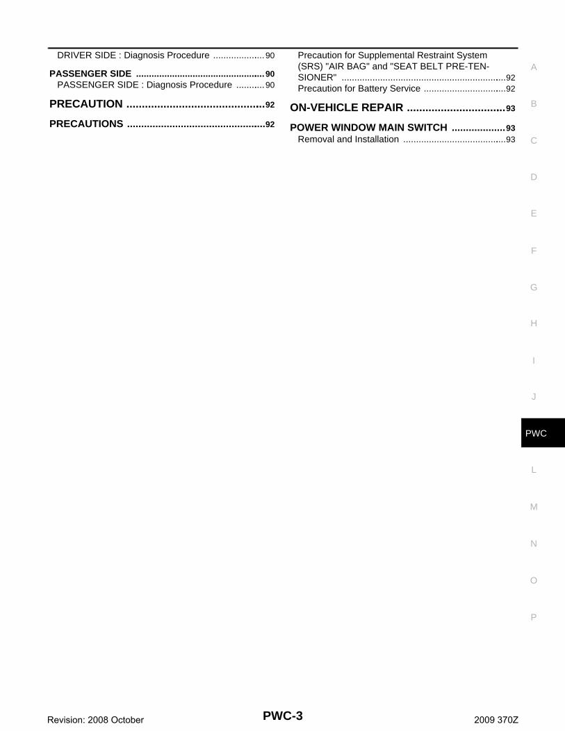
ADDITIONAL SERVICE WHEN REMOVING BATTERY NEGATIVE TERMINAL : De-scription INFOID:0000000004460994
When the battery negative terminal is disconnected, the initialization is necessary.If any of the following operations are performed, the initialization is necessary as well as when the negativebattery terminal is disconnected.• Power supply to the power window switch or power window motor is cut off by removal of battery terminal or
if the battery fuse is blown.• Disconnection and connection of power window switch harness connector.• Removal and installation of motor from regulator assembly.• Operation of regulator assembly as an independent unit.• Removal and installation of door glass or door glass run.The following specified operations cannot be performed under the non initialized condition.• Auto-up operation• Anti-pinch function• Key cylinder switch power window function• Automatic window adjusting function
ADDITIONAL SERVICE WHEN REMOVING BATTERY NEGATIVE TERMINAL : Spe-cial Repair Requirement INFOID:0000000004460995
INITIALIZATION PROCEDURE1. Disconnect battery negative terminal or power window switch connector. Reconnect it after a minute or
more. 2. Door switch is OFF (close).3. Turn ignition switch ON.4. Operate power window switch to fully open the window. (This operation is unnecessary if the window is
already fully open.)5. Continue pulling the power window switch AUTO-UP. Even after glass stops at the fully closed position,
keep pulling the switch for 3 seconds or more. 6. Initializing procedure is completed.7. Inspect anti-pinch function.CAUTION:When initialization is not complete, power window UP does not operate while door is open.
CHECK ANTI-PINCH FUNCTION1. Fully open the door window.2. Place a piece of wood near the fully closed position.3. Close door glass completely with AUTO-UP.• Check that glass lowers for approximately 150 mm (5.9 in) without pinching piece of wood and stops.• Check that glass does not rise when operating the power window main switch while lowering.CAUTION:• Never check with hands and other part of body because they may be pinched. Never get pinched.• Check that AUTO-UP operates before inspection when system initialization is performed.• It may switch to fail-safe mode if open/close operation is performed continuously. Perform initial
setting in that situation. Refer to PWC-70, "Fail-Safe"• Perform initial setting when auto-up operation or anti-pinch function does not operate normally.• Finish initial setting. Otherwise, next operation cannot be performed.1. Auto-up operation2. Anti-pinch function3. Key cylinder switch power window function4. Automatic window adjusting function5. Auto-up, manual-up does not operate when door is open ADDITIONAL SERVICE WHEN REPLACING CONTROL UNIT
PWC-5Revision: 2008 October 2009 370Z

INSPECTION AND ADJUSTMENT
< BASIC INSPECTION >ADDITIONAL SERVICE WHEN REPLACING CONTROL UNIT : DescriptionINFOID:0000000004460996
When the control unit is replaced, the initialization is necessary.If any of the following operations are performed, the initialization is necessary and the control unit must be dis-connected.• Power supply to the power window switch or power window motor is cut off by removal of battery terminal or
if the battery fuse is blown.• Disconnection and connection of power window switch harness connector.• Removal and installation of motor from regulator assembly.• Operation of regulator assembly as an independent unit.• Removal and installation of door glass or door glass run.The following specified operations cannot be performed under the non initialized condition.• Auto-up operation• Anti-pinch function• Key cylinder switch power window function• Automatic window adjusting function
ADDITIONAL SERVICE WHEN REPLACING CONTROL UNIT : Special Repair Re-quirement INFOID:0000000004460997
INITIALIZATION PROCEDURE1. Disconnect battery negative terminal or power window switch connector. Reconnect it after a minute or
more. 2. Door switch is OFF (close).3. Turn ignition switch ON.4. Operate power window switch to fully open the window. (This operation is unnecessary if the window is
already fully open.)5. Continue pulling the power window switch AUTO-UP. Even after glass stops at the fully closed position,
keep pulling the switch for 3 seconds or more. 6. Initializing procedure is completed.7. Inspect anti-pinch function.CAUTION:When initialization is not complete, power window UP does not operate while door is open.
CHECK ANTI-PINCH FUNCTION1. Fully open the door window.2. Place a piece of wood near the fully closed position.3. Close door glass completely with AUTO-UP.• Check that glass lowers for approximately 150 mm (5.9 in) without pinching piece of wood and stops.• Check that glass does not rise when operating the power window switch while lowering.CAUTION:• Never check with hands and other part of body because they may be pinched. Never get pinched.• Check that AUTO-UP operates before inspection when system initialization is performed.• It may switch to fail-safe mode if open/close operation is performed continuously. Perform initial
setting in that situation. Refer to PWC-70, "Fail-Safe"• Perform initial setting when auto-up operation or anti-pinch function does not operate normally.• Finish initial setting. Otherwise, next operation cannot be performed.1. Auto-up operation2. Anti-pinch function3. Key cylinder switch power window function4. Automatic window adjusting function5. Auto-up, manual-up does not operate when door is open
PWC-6Revision: 2008 October 2009 370Z

POWER WINDOW SYSTEM
C
D
E
F
G
H
I
J
L
M
A
B
WC
N
O
P
< FUNCTION DIAGNOSIS >
P
FUNCTION DIAGNOSISPOWER WINDOW SYSTEM
System Diagram INFOID:0000000004460998
System Description INFOID:0000000004460999
POWER WINDOW SYSTEM• Power window system is activated by power window switch operation when ignition switch is turned ON and
during the retained power operation, after ignition switch turned OFF.• Power window main switch can open/close all windows.• Power window sub-switch can open/close the passenger side windows.• AUTO operation can be activated by operating the power window switch once.• It transmits and receives the signal between BCM and power window main switch or power window sub
switch, via serial communication.• When pressing power window lock switch, operation other than power window main switch becomes impos-
sible.• When detecting the pinching resistance of foreign materials, etc. during power window AUTO UP operation,
it lowers door glass to the specified value.• When opening driver side or passenger side door while door glass is being fully closed, it lowers door glass
of the door a little from the closed position. When closing the door, it return door glass to the fully closedposition.
• All power windows open or close when Intelligent Key unlock button is pressed for 3seconds.• Hold the door key cylinder to the LOCK or UNLOCK direction for 1 second or more to OPEN or CLOSE all
power windows when ignition switch OFF.
POWER WINDOW AUTO-OPERATION• AUTO UP/DOWN operation can be performed when power window main switch turns to AUTO.• Encoder continues detecting the movement of power window motor and transmits to power window switch
as the encoder pulse signal while power window motor is operating.• Power window switch reads the changes of encoder signal and stops AUTO operation when door glass is at
the fully open/closed position.• Auto function is inoperable if encoder is malfunctioning.
JMKIA3418GB
PWC-7Revision: 2008 October 2009 370Z
POWER WINDOW SYSTEM
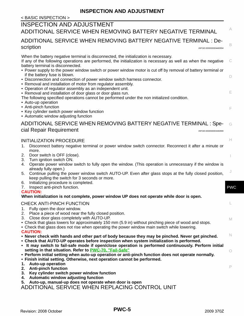
< FUNCTION DIAGNOSIS >POWER WINDOW SERIAL LINKPower window main switch, power window sub-switch and BCM transmit and receive the signal by power win-dow serial link.The under mentioned signal is transmitted from BCM to power window main switch.• Driver side door switch signal.• Keyless power window down signal.• Retained power operation signal. The under mentioned signal is transmitted from BCM to power window sub-switch.• Passenger side door switch signal.• Keyless power window down signal.• Retained power operation signal. The following signal is transmitted from power window main switch to power window sub-switch.• Passenger side door window operation signal.• Power window lock signal.• Power window control by key cylinder switch signal.
RETAINED POWER OPERATIONRetained power operation is an additional power supply function that enables power window system to oper-ate for 45 seconds after ignition switch turns OFF.RETAINED POWER FUNCTION CANCEL CONDITIONS• Front door CLOSED (door switch OFF) → OPEN (door switch ON).• When ignition switch turns ON again.• When timer times out. (45 seconds)
POWER WINDOW LOCK FUNCTIONGround circuit inside power window main switch shuts off when power window lock switch is ON. This inhibitspower window switch operation except with the power window main switch.
ANTI-PINCH FUNCTION• The anti-pinch function detects foreign matter being pinched in the door glass, during AUTO-UP operation,
and lowers the door glass 150 mm (5.9in).• Encoder continues detecting the movement of power window motor and transmits to power window switch
as the encoder pulse signal while power window motor is operating.• Resistance is applied to the power window motor rotation that changes the frequency of encoder pulse sig-
nal if foreign material is trapped in the door glass.• Power window switch controls to lower the door glass for 150 mm (5.9in) after it detects encoder pulse signal
frequency change.OPERATION CONDITION• When all door glass AUTO-UP operation is performed (anti-pinch function does not operate just before the
door glass closes and is fully closed.)NOTE:Depending on environment and driving conditions, if a similar impact or load is applied to the door glass, itmay lower.
AUTOMATIC WINDOW ADJUSTING FUNCTIONWhen the driver/passenger door(s) is open, the window of the opened door is lowered approximately 10 mm(0.39 in).When the door is closed, the window is raised to the fully closed position.Automatic window adjusting function system (opening operation) does not operate when the following itemoccurs.• The window is 10 mm (0.39 in) or more open from the fully closed position.Automatic window adjusting function system (closing operation) does not operate when the following itemoccurs.• The automatic window adjusting function system (opening operation) operation.
DOOR KEY CYLINDER SWITCH POWER WINDOW FUNCTIONHold the door key cylinder to the LOCK or UNLOCK position for 1 second or more to OPEN or CLOSE allpower windows when ignition switch is OFF. In addition, it stops when the key position is NEUTRAL whenoperating.OPERATION CONDITION• Ignition switch OFF.• Hold door key cylinder to the LOCK position for 1 second or more to perform CLOSE operation of the door
glass.
PWC-8Revision: 2008 October 2009 370Z

POWER WINDOW SYSTEM
C
D
E
F
G
H
I
J
L
M
A
B
WC
N
O
P
< FUNCTION DIAGNOSIS >
P
• Hold door key cylinder in the UNLOCK position for 1 second or more to perform OPEN operation of the doorglass.
KEYLESS POWER WINDOW DOWN FUNCTIONAll power windows open when the unlock button on Intelligent Key is activated and pressed and held for morethan 3* seconds with the ignition switch OFF. The windows keep opening if the unlock button is continuouslypressed.The power window opening function stops when the following operations are performed.• When the unlock button is pressed and held for more than 15 seconds.• When the ignition switch is turned ON while the power window opening is operated.• When the unlock button is released.While retained power operation activates, keyless power window down function cannot be operated.Keyless power window down operation mode can be changed by “PW DOWN SET” mode in “WORK SUP-PORT”. Refer to DLK-49, "INTELLIGENT KEY : CONSULT-III Function (BCM - INTELLIGENT KEY)".NOTE:Use CONSULT-III to change settings.MODE 1 (3 sec) / MODE 2 (OFF) / MODE 3 (5 sec)
POWER CONSUMPTION CONTROL SYSTEMPower window switch incorporates a power consumption control function that reduces the power consumptionaccording the vehicle status.LOW POWER CONSUMPTION MODE• Ignition switch OFF.• Power window main switch and power window sub-switch do not receive a signal from serial link.• Power window motor does not move.If any of the following conditions are satisfied, the low power consumption mode is released.• Ignition switch ON.• When door key cylinder switch signal is received.• When door lock signal is received.• When the signal is received from serial link.
PWC-9Revision: 2008 October 2009 370Z

POWER WINDOW SYSTEM
< FUNCTION DIAGNOSIS >Component Parts Location INFOID:0000000004461000
Component Description INFOID:0000000004461001
1. BCM M118, M119, M122, M123BCS-8, "Component Parts Location"
2. Remote keyless entry receiver M104DLK-30, "REMOTE KEYLESS EN-TRY FUNCTION : Component Parts Location"
3. Driver side door lock assembly(door key cylinder switch) D15
4. Driver side power window motor D10 5. Driver side door switch B16 6. Power window main switch D8
A. View with door finisher removed
JMKIA3417GB
Component Function
BCM• Supplies power to power window switches.• Controls retained power function
Power window main switch• Directly controls all power window motors in all doors.• Controls anti-pinch operation of power window.
Power window sub-switch• Controls anti-pinch operation of power window.• Controls power window motor of passenger door.
Power window motor• Integrates the encoder and window motor.• Starts operating with signals from each power window switch.• Transmits power window motor rotation as a pulse signal to power window switch.
PWC-10Revision: 2008 October 2009 370Z

POWER WINDOW SYSTEM
C
D
E
F
G
H
I
J
L
M
A
B
WC
N
O
P
< FUNCTION DIAGNOSIS >
P
Driver side door lock assembly (door key cylinder switch)
Transmits operation condition of key cylinder switch to power window main switch.
Remote keyless entry receiver Receives lock/unlock signal from intelligent key, and then transmits to BCM.
Door switch Detects door open/close condition and transmits to BCM.
Component Function
PWC-11Revision: 2008 October 2009 370Z
DIAGNOSIS SYSTEM (BCM)
< FUNCTION DIAGNOSIS >DIAGNOSIS SYSTEM (BCM)COMMON ITEM
COMMON ITEM : CONSULT-III Function (BCM - COMMON ITEM) INFOID:0000000004555918
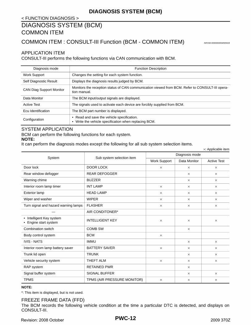
APPLICATION ITEMCONSULT-III performs the following functions via CAN communication with BCM.
SYSTEM APPLICATIONBCM can perform the following functions for each system.NOTE:It can perform the diagnosis modes except the following for all sub system selection items.
×: Applicable item
NOTE:
*: This item is displayed, but is not used.
FREEZE FRAME DATA (FFD)The BCM records the following vehicle condition at the time a particular DTC is detected, and displays onCONSULT-III.
Diagnosis mode Function Description
Work Support Changes the setting for each system function.
Self Diagnostic Result Displays the diagnosis results judged by BCM.
CAN Diag Support MonitorMonitors the reception status of CAN communication viewed from BCM. Refer to CONSULT-III opera-tion manual.
Data Monitor The BCM input/output signals are displayed.
Active Test The signals used to activate each device are forcibly supplied from BCM.
Ecu Identification The BCM part number is displayed.
Configuration• Read and save the vehicle specification.• Write the vehicle specification when replacing BCM.
System Sub system selection itemDiagnosis mode
Work Support Data Monitor Active Test
Door lock DOOR LOCK × × ×
Rear window defogger REAR DEFOGGER × ×
Warning chime BUZZER × ×
Interior room lamp timer INT LAMP × × ×
Exterior lamp HEAD LAMP × × ×
Wiper and washer WIPER × × ×
Turn signal and hazard warning lamps FLASHER × × ×
— AIR CONDITONER*
• Intelligent Key system• Engine start system
INTELLIGENT KEY × × ×
Combination switch COMB SW ×
Body control system BCM ×
IVIS - NATS IMMU × ×
Interior room lamp battery saver BATTERY SAVER × × ×
Trunk lid open TRUNK × ×
Vehicle security system THEFT ALM × × ×
RAP system RETAINED PWR ×
Signal buffer system SIGNAL BUFFER × ×
TPMS TPMS (AIR PRESSURE MONITOR) × × ×
PWC-12Revision: 2008 October 2009 370Z
DIAGNOSIS SYSTEM (BCM)
C
D
E
F
G
H
I
J
L
M
A
B
WC
N
O
P
< FUNCTION DIAGNOSIS >
P
RETAINED PWR
RETAINED PWR : CONSULT-III Function (BCM - RETAINED PWR) INFOID:0000000004747508
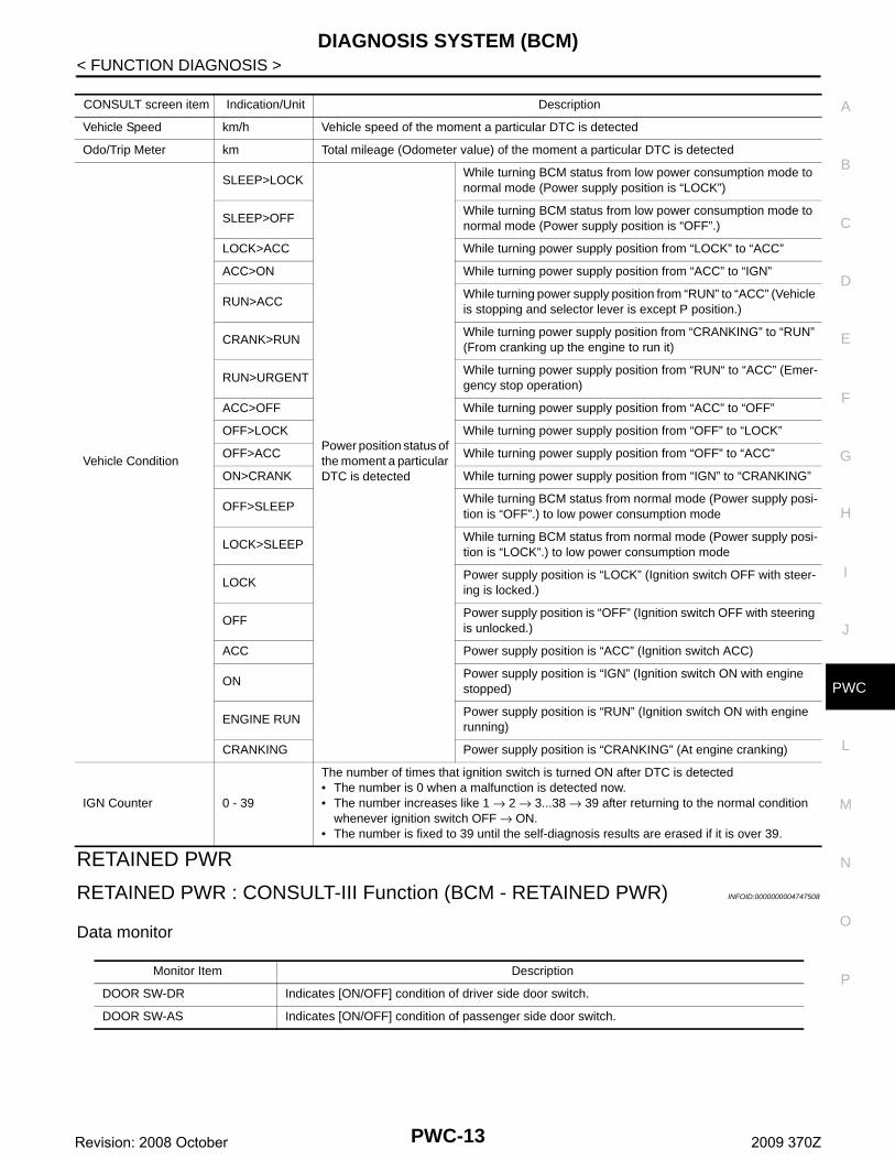
Data monitor
CONSULT screen item Indication/Unit Description
Vehicle Speed km/h Vehicle speed of the moment a particular DTC is detected
Odo/Trip Meter km Total mileage (Odometer value) of the moment a particular DTC is detected
Vehicle Condition
SLEEP>LOCK
Power position status of the moment a particular DTC is detected
While turning BCM status from low power consumption mode to normal mode (Power supply position is “LOCK”)
SLEEP>OFFWhile turning BCM status from low power consumption mode to normal mode (Power supply position is “OFF”.)
LOCK>ACC While turning power supply position from “LOCK” to “ACC”
ACC>ON While turning power supply position from “ACC” to “IGN”
RUN>ACCWhile turning power supply position from “RUN” to “ACC” (Vehicle is stopping and selector lever is except P position.)
CRANK>RUNWhile turning power supply position from “CRANKING” to “RUN” (From cranking up the engine to run it)
RUN>URGENTWhile turning power supply position from “RUN“ to “ACC” (Emer-gency stop operation)
ACC>OFF While turning power supply position from “ACC” to “OFF”
OFF>LOCK While turning power supply position from “OFF” to “LOCK”
OFF>ACC While turning power supply position from “OFF” to “ACC”
ON>CRANK While turning power supply position from “IGN” to “CRANKING”
OFF>SLEEPWhile turning BCM status from normal mode (Power supply posi-tion is “OFF”.) to low power consumption mode
LOCK>SLEEPWhile turning BCM status from normal mode (Power supply posi-tion is “LOCK”.) to low power consumption mode
LOCKPower supply position is “LOCK” (Ignition switch OFF with steer-ing is locked.)
OFFPower supply position is “OFF” (Ignition switch OFF with steering is unlocked.)
ACC Power supply position is “ACC” (Ignition switch ACC)
ONPower supply position is “IGN” (Ignition switch ON with engine stopped)
ENGINE RUNPower supply position is “RUN” (Ignition switch ON with engine running)
CRANKING Power supply position is “CRANKING” (At engine cranking)
IGN Counter 0 - 39
The number of times that ignition switch is turned ON after DTC is detected• The number is 0 when a malfunction is detected now.• The number increases like 1 → 2 → 3...38 → 39 after returning to the normal condition
whenever ignition switch OFF → ON.• The number is fixed to 39 until the self-diagnosis results are erased if it is over 39.
Monitor Item Description
DOOR SW-DR Indicates [ON/OFF] condition of driver side door switch.
DOOR SW-AS Indicates [ON/OFF] condition of passenger side door switch.
PWC-13Revision: 2008 October 2009 370Z

POWER SUPPLY AND GROUND CIRCUIT
< COMPONENT DIAGNOSIS >COMPONENT DIAGNOSISPOWER SUPPLY AND GROUND CIRCUITBCM
BCM : Diagnosis Procedure INFOID:0000000004461002
1.CHECK FUSE AND FUSIBLE LINK
Check that the following fuse and fusible link are not blown.
Is the fuse fusing?YES >> Replace the blown fuse or fusible link after repairing the affected circuit if a fuse or fusible link is
blown.NO >> GO TO 2.
2.CHECK POWER SUPPLY CIRCUIT
1. Turn ignition switch OFF.2. Disconnect BCM connectors.3. Check voltage between BCM harness connector and ground.
Is the measurement value normal?YES >> GO TO 3.NO >> Repair or replace harness.
3.CHECK GROUND CIRCUIT
Check continuity between BCM harness connector and ground.
Does continuity exist?YES >> INSPECTION ENDNO >> Repair harness or connector.
POWER WINDOW MAIN SWITCH
POWER WINDOW MAIN SWITCH : Diagnosis Procedure INFOID:0000000004461003
1.CHECK POWER SUPPLY CIRCUIT 1
1. Turn ignition switch OFF.2. Disconnect power window main switch connector.3. Turn ignition switch ON.4. Check voltage between power window main switch harness connector and ground.
Terminal No. Signal name Fuse and fusible link No.
1Battery power supply
K (40A)
11 10 (10A)
(+)
(−)Voltage
(Approx.)BCM
Connector Terminal
M118 1Ground Battery voltage
M119 11
BCM
GroundContinuity
Connector Terminal
M119 13 Existed
PWC-14Revision: 2008 October 2009 370Z

POWER SUPPLY AND GROUND CIRCUIT
C
D
E
F
G
H
I
J
L
M
A
B
WC
N
O
P
< COMPONENT DIAGNOSIS >
P
Is the measurement value within the specification?YES >> GO TO 3.NO >> GO TO 2.
2.CHECK POWER SUPPLY CIRCUIT 2
1. Turn ignition switch OFF.2. Disconnect BCM connector.3. Check continuity between BCM harness connector and power window main switch harness connector.
4. Check continuity between BCM harness connector and ground.
Is the inspection result normal?YES >> Replace BCM. Refer to BCS-84, "Exploded View".NO >> Repair or replace harness.
3.CHECK GROUND CIRCUIT
1. Turn ignition switch OFF.2. Check continuity between power window main switch harness connector and ground.
Is the inspection result normal?YES >> INSPECTION ENDNO >> Repair or replace harness.
POWER WINDOW SUB-SWITCH
POWER WINDOW SUB-SWITCH : Diagnosis Procedure INFOID:0000000004461004
1.CHECK POWER SUPPLY CIRCUIT 1
1. Turn ignition switch OFF.2. Disconnect power window sub-switch connector.3. Check voltage between power window sub-switch harness connector and ground.
(+)
(–)Voltage (V)(Approx.)
Power window main switch
Connector Terminal
D8 1
Ground Battery voltage10
BCM Power window main switchContinuity
Connector Terminal Connector Terminal
M1182
D81
Existed3 10
BCM
Ground
Continuity Connector Terminal
M1182
Not existed3
Power window main switch
GroundContinuity
Connector Terminal
D8 15 Existed
(+)
(–)Voltage (V)(Approx.)
Power window sub-switch
Connector Terminal
D38 10 Ground Battery voltage
PWC-15Revision: 2008 October 2009 370Z
POWER SUPPLY AND GROUND CIRCUIT
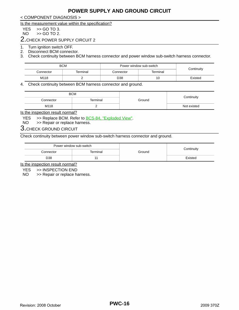
< COMPONENT DIAGNOSIS >Is the measurement value within the specification?YES >> GO TO 3.NO >> GO TO 2.2.CHECK POWER SUPPLY CIRCUIT 2
1. Turn ignition switch OFF.2. Disconnect BCM connector.3. Check continuity between BCM harness connector and power window sub-switch harness connector.
4. Check continuity between BCM harness connector and ground.
Is the inspection result normal?YES >> Replace BCM. Refer to BCS-84, "Exploded View".NO >> Repair or replace harness.
3.CHECK GROUND CIRCUIT
Check continuity between power window sub-switch harness connector and ground.
Is the inspection result normal?YES >> INSPECTION ENDNO >> Repair or replace harness.
BCM Power window sub-switchContinuity
Connector Terminal Connector Terminal
M118 2 D38 10 Existed
BCM
GroundContinuity
Connector Terminal
M118 2 Not existed
Power window sub-switch
GroundContinuity
Connector Terminal
D38 11 Existed
PWC-16Revision: 2008 October 2009 370Z

POWER WINDOW MOTOR
C
D
E
F
G
H
I
J
L
M
A
B
WC
N
O
P
< COMPONENT DIAGNOSIS >
P
POWER WINDOW MOTORDRIVER SIDE
DRIVER SIDE : Description INFOID:0000000004461005
Door glass moves UP/DOWN by receiving the signal from power window main switch.
DRIVER SIDE : Component Function Check INFOID:0000000004461006
1.CHECK POWER WINDOW MOTOR CIRCUIT
Check driver side power window motor operation with power window main switch.Is the inspection result normal?YES >> Driver side power window motor is OK.NO >> Refer to PWC-17, "DRIVER SIDE : Diagnosis Procedure".
DRIVER SIDE : Diagnosis Procedure INFOID:0000000004461007
1.CHECK POWER WINDOW MAIN SWITCH OUTPUT SIGNAL
1. Turn ignition switch OFF.2. Disconnect driver side power window motor connector.3. Turn ignition switch ON.4. Check voltage between driver side power window motor harness connector and ground.
Is the measurement value within the specification?YES >> GO TO 2.NO >> GO TO 3.
2.CHECK POWER WINDOW MOTOR
Check driver side power window motor.Refer to PWC-18, "DRIVER SIDE : Component Inspection".Is the inspection result normal?YES >> GO TO 4.NO >> Replace driver side power window motor. Refer to GW-21, "Removal and Installation".
3.CHECK POWER WINDOW MOTOR CIRCUIT
1. Turn ignition switch OFF.2. Disconnect power window main switch connector.3. Check continuity between power window main switch harness connector and driver side power window
motor harness connector.
4. Check continuity between power window main switch harness connector and ground.
(+)
(–) ConditionVoltage (V)(Approx.)
Driver side power window motor
Connector Terminal
D10
6
GroundPower window main switch
UP Battery voltage
DOWN 0
3UP 0
DOWN Battery voltage
Power window main switch Driver side power window motorContinuity
Connector Terminal Connector Terminal
D88
D106
Existed11 3
PWC-17Revision: 2008 October 2009 370Z

POWER WINDOW MOTOR
< COMPONENT DIAGNOSIS >Is the inspection result normal?YES >> Replace power window main switch. Refer to PWC-93, "Removal and Installation".NO >> Repair or replace harness.
4.CHECK INTERMITTENT INCIDENT
Refer to GI-39, "Intermittent Incident".
>> INSPECTION END
DRIVER SIDE : Component Inspection INFOID:0000000004461008
COMPONENT INSPECTION
1.CHECK DRIVER SIDE POWER WINDOW MOTOR
1. Turn ignition switch OFF.2. Disconnect driver side power window motor connector.3. Check motor operation by connecting the battery voltage directly to driver side power window motor con-
nector.
Is the inspection result normal?YES >> Driver side power window motor is OK.NO >> Replace driver side power window motor. Refer to GW-21, "Removal and Installation".
PASSENGER SIDE
PASSENGER SIDE : Description INFOID:0000000004461009
Door glass moves UP/DOWN by receiving the signal power window main switch or power window sub-switch .
PASSENGER SIDE : Component Function Check INFOID:0000000004461010
1. CHECK POWER WINDOW MOTOR CIRCUIT
Check passenger side power window motor operation with power window main switch or power window subswitch.Is the inspection result normal?YES >> Passenger side power window motor is OK.NO >> Refer to PWC-18, "PASSENGER SIDE : Diagnosis Procedure".
PASSENGER SIDE : Diagnosis Procedure INFOID:0000000004461011
1.CHECK POWER WINDOW SUB-SWITCH OUTPUT SIGNAL
1. Turn ignition switch OFF.2. Disconnect passenger side power window motor connector.3. Turn ignition switch ON.4. Check voltage between passenger side power window motor harness connector and ground.
Power window main switch
Ground
ContinuityConnector Terminal
D88
Not existed11
Driver side power window mo-tor connector
TerminalMotor operation
(+) (–)
D103 6 DOWN
6 3 UP
PWC-18Revision: 2008 October 2009 370Z

POWER WINDOW MOTOR
C
D
E
F
G
H
I
J
L
M
A
B
WC
N
O
P
< COMPONENT DIAGNOSIS >
P
Is the measurement value within the specification?YES >> GO TO 2.NO >> GO TO 3.
2.CHECK PASSENGER SIDE POWER WINDOW MOTOR
Check passenger side power window motor. Refer to PWC-19, "PASSENGER SIDE : Component Inspection".Is the inspection result normal?YES >> GO TO 4.NO >> Replace passenger side power window motor. Refer to GW-21, "Removal and Installation".
3.CHECK POWER WINDOW MOTOR CIRCUIT
1. Turn ignition switch OFF.2. Disconnect power window sub-switch connector.3. Check continuity between power window sub-switch harness connector and passenger side power win-
dow motor harness connector.
4. Check continuity between power window sub-switch connector and ground.
Is the inspection result normal?YES >> Replace power window sub-switch. Refer to PWC-93, "Removal and Installation".NO >> Repair or replace harness.
4.CHECK INTERMITTENT INCIDENT
Refer to GI-39, "Intermittent Incident".
>> INSPECTION END
PASSENGER SIDE : Component Inspection INFOID:0000000004461012
COMPONENT INSPECTION
1.CHECK PASSENGER SIDE POWER WINDOW MOTOR
1. Turn ignition switch OFF.2. Disconnect passenger side power window motor connector.3. Check motor operation by connecting the battery voltage directly to passenger side power window motor
connector.
(+)(–)
ConditionVoltage (V)(Approx.)
Passenger side power window motor
Connector Terminal
D40
6
GroundPower window sub- switch
UP Battery voltage
DOWN 0
3UP 0
DOWN Battery voltage
Power window sub-switch Passenger side power window motorContinuity
Connector Terminal Connector Terminal
D389
D403
Existed8 6
Power window sub-switch
Ground
ContinuityConnector Terminal
D388
Not existed9
PWC-19Revision: 2008 October 2009 370Z

POWER WINDOW MOTOR
< COMPONENT DIAGNOSIS >Is the inspection result normal?YES >> Passenger side power window motor is OK.NO >> Replace passenger side power window motor. Refer to GW-21, "Removal and Installation".
Passenger side power window motor connector
TerminalMotor condition
(+) (–)
D403 6 DOWN
6 3 UP
PWC-20Revision: 2008 October 2009 370Z

ENCODER
C
D
E
F
G
H
I
J
L
M
A
B
WC
N
O
P
< COMPONENT DIAGNOSIS >
P
ENCODERDRIVER SIDE
DRIVER SIDE : Description INFOID:0000000004461013
Detects condition of the driver side power window motor operation and transmits to power window main switchas the pulse signal.
DRIVER SIDE : Component Function Check INFOID:0000000004461014
1.CHECK ENCODER OPERATION
Check that driver side door glass performs AUTO open/close operation normally with power window mainswitch.Is the inspection result normal?YES >> Encoder operation is OK.NO >> Refer to PWC-21, "DRIVER SIDE : Diagnosis Procedure".
DRIVER SIDE : Diagnosis Procedure INFOID:0000000004461015
1.CHECK ENCODER OPERATION
1. Turn ignition switch ON.2. Check signal between power window main switch harness connector and ground with oscilloscope.
Is the inspection result normal?YES >> Replace power window main switch. Refer to PWC-93, "Removal and Installation". NO >> GO TO 2.
2.CHECK ENCODER SIGNAL CIRCUIT
1. Turn ignition switch OFF.2. Disconnect power window main switch connector and driver side power window motor connector.3. Check continuity between power window main switch harness connector and driver side power window
motor harness connector.
4. Check continuity between power window main switch harness connector and ground.
(+)
(–)Signal
(Reference value) Power window main switch
Connector Terminal
D89
Ground Refer to the following signal13
JMKIA2682GB
Power window main switch Driver side power window motorContinuity
Connector Terminal Connector Terminal
D89
D105
Existed13 2
PWC-21Revision: 2008 October 2009 370Z

ENCODER
< COMPONENT DIAGNOSIS >Is the inspection result normal?YES >> GO TO 3.NO >> Repair or replace harness.
3.CHECK ENCODER POWER SUPPLY CIRCUIT 1
1. Connect power window main switch connector.2. Turn ignition switch ON.3. Check voltage between driver side power window motor harness connector and ground.
Is the measurement value within the specification?YES >> GO TO 5.NO >> GO TO 4.
4.CHECK ENCODER POWER SUPPLY CIRCUIT 2
1. Turn ignition switch OFF.2. Disconnect power window main switch connector.3. Check continuity between power window main switch harness connector and driver side power window
motor harness connector.
4. Check continuity between power window main switch harness connector and ground.
Is the inspection result normal?YES >> Replace power window main switch. Refer to PWC-93, "Removal and Installation". NO >> Repair or replace harness.
5.CHECK GROUND CIRCUIT 1
1. Turn ignition switch OFF.2. Disconnect power window main switch connector.3. Check continuity between power window main switch harness connector and driver side power window
motor harness connector.
Is the inspection result normal?YES >> GO TO 6.NO >> Repair or replace harness.
6.CHECK GROUND CIRCUIT 2
Power window main switch
Ground
Continuity Connector Terminal
D89
Not existed13
(+)
(–)Voltage (V)(Approx.)
Driver side power window motor
Connector Terminal
D10 4 Ground Battery voltage
Power window main switch Driver side power window motorContinuity
Connector Terminal Connector Terminal
D8 5 D10 4 Existed
Power window main switch
GroundContinuity
Connector Terminal
D8 5 Not existed
Power window main switch Driver side power window motorContinuity
Connector Terminal Connector Terminal
D8 14 D10 1 Existed
PWC-22Revision: 2008 October 2009 370Z
ENCODER
C
D
E
F
G
H
I
J
L
M
A
B
WC
N
O
P
< COMPONENT DIAGNOSIS >
P
1. Connect power window main switch connector.2. Check continuity between power window main switch harness connector and ground.
Is the inspection result normal?YES >> Replace driver side power window motor. Refer to PWC-93, "Removal and Installation". NO >> Replace power window main switch. Refer to PWC-93, "Removal and Installation".
PASSENGER SIDE
PASSENGER SIDE : Description INFOID:0000000004461016
Detects condition of the passenger side power window motor operation and transmits to power window sub-switch as the pulse signal.
PASSENGER SIDE : Component Function Check INFOID:0000000004461017
1.CHECK ENCODER OPERATION
Check that passenger side door glass performs AUTO open operation normally with power window mainswitch or power window sub-switch.Is the inspection result normal?YES >> Encoder operation is OK.NO >> Refer to PWC-23, "PASSENGER SIDE : Diagnosis Procedure".
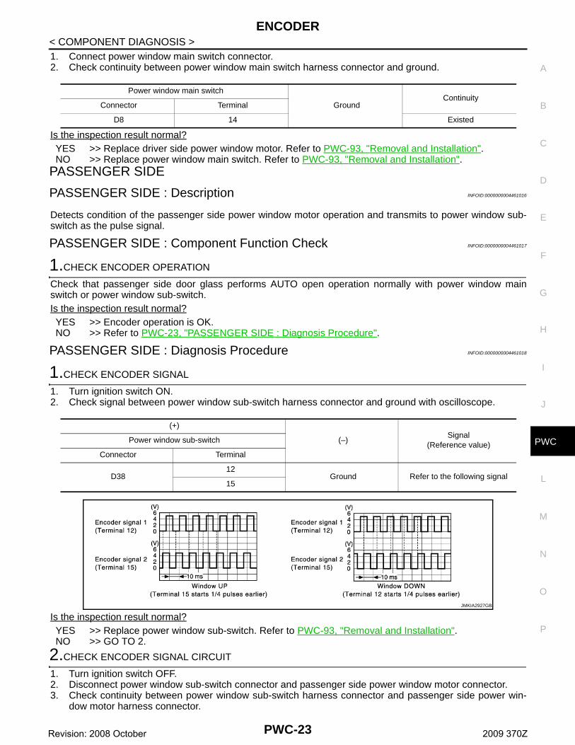
PASSENGER SIDE : Diagnosis Procedure INFOID:0000000004461018
1.CHECK ENCODER SIGNAL
1. Turn ignition switch ON.2. Check signal between power window sub-switch harness connector and ground with oscilloscope.
Is the inspection result normal?YES >> Replace power window sub-switch. Refer to PWC-93, "Removal and Installation". NO >> GO TO 2.
2.CHECK ENCODER SIGNAL CIRCUIT
1. Turn ignition switch OFF.2. Disconnect power window sub-switch connector and passenger side power window motor connector.3. Check continuity between power window sub-switch harness connector and passenger side power win-
dow motor harness connector.
Power window main switch
GroundContinuity
Connector Terminal
D8 14 Existed
(+)
(–)Signal
(Reference value)Power window sub-switch
Connector Terminal
D3812
Ground Refer to the following signal15
JMKIA2927GB
PWC-23Revision: 2008 October 2009 370Z
ENCODER
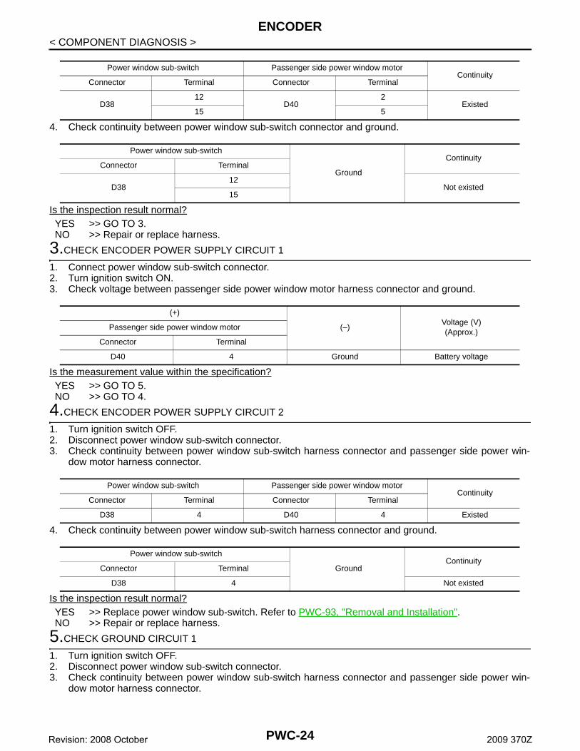
< COMPONENT DIAGNOSIS >4. Check continuity between power window sub-switch connector and ground.
Is the inspection result normal?YES >> GO TO 3.NO >> Repair or replace harness.
3.CHECK ENCODER POWER SUPPLY CIRCUIT 1
1. Connect power window sub-switch connector.2. Turn ignition switch ON.3. Check voltage between passenger side power window motor harness connector and ground.
Is the measurement value within the specification?YES >> GO TO 5.NO >> GO TO 4.
4.CHECK ENCODER POWER SUPPLY CIRCUIT 2
1. Turn ignition switch OFF.2. Disconnect power window sub-switch connector.3. Check continuity between power window sub-switch harness connector and passenger side power win-
dow motor harness connector.
4. Check continuity between power window sub-switch harness connector and ground.
Is the inspection result normal?YES >> Replace power window sub-switch. Refer to PWC-93, "Removal and Installation". NO >> Repair or replace harness.
5.CHECK GROUND CIRCUIT 1
1. Turn ignition switch OFF.2. Disconnect power window sub-switch connector.3. Check continuity between power window sub-switch harness connector and passenger side power win-
dow motor harness connector.
Power window sub-switch Passenger side power window motorContinuity
Connector Terminal Connector Terminal
D3812
D402
Existed15 5
Power window sub-switch
Ground
Continuity Connector Terminal
D3812
Not existed15
(+)
(–)Voltage (V)(Approx.)
Passenger side power window motor
Connector Terminal
D40 4 Ground Battery voltage
Power window sub-switch Passenger side power window motorContinuity
Connector Terminal Connector Terminal
D38 4 D40 4 Existed
Power window sub-switch
GroundContinuity
Connector Terminal
D38 4 Not existed
PWC-24Revision: 2008 October 2009 370Z

ENCODER
C
D
E
F
G
H
I
J
L
M
A
B
WC
N
O
P
< COMPONENT DIAGNOSIS >
P
Is the inspection result normal?YES >> GO TO 6.NO >> Repair or replace harness.
6.CHECK GROUND CIRCUIT 2
1. Connect power window sub-switch connector.2. Check continuity between power window sub-switch harness connector and ground.
Is the inspection result normal?YES >> Replace passenger side power window motor. Refer to PWC-93, "Removal and Installation". NO >> Replace power window sub-switch. Refer to PWC-93, "Removal and Installation".
Power window sub-switch Passenger side power window motorContinuity
Connector Terminal Connector Terminal
D38 3 D40 1 Existed
Power window sub-switch
GroundContinuity
Connector Terminal
D38 3 Existed
PWC-25Revision: 2008 October 2009 370Z
POWER WINDOW SERIAL LINK
< COMPONENT DIAGNOSIS >POWER WINDOW SERIAL LINKPOWER WINDOW MAIN SWITCH
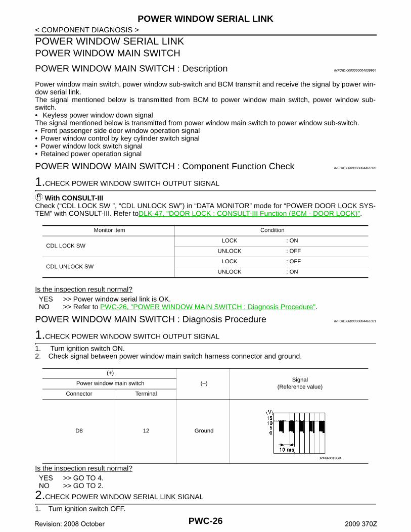
POWER WINDOW MAIN SWITCH : Description INFOID:0000000004639964
Power window main switch, power window sub-switch and BCM transmit and receive the signal by power win-dow serial link.The signal mentioned below is transmitted from BCM to power window main switch, power window sub-switch.• Keyless power window down signalThe signal mentioned below is transmitted from power window main switch to power window sub-switch.• Front passenger side door window operation signal• Power window control by key cylinder switch signal• Power window lock switch signal• Retained power operation signal
POWER WINDOW MAIN SWITCH : Component Function Check INFOID:0000000004461020
1.CHECK POWER WINDOW SWITCH OUTPUT SIGNAL
With CONSULT-IIICheck (“CDL LOCK SW ”, “CDL UNLOCK SW”) in “DATA MONITOR” mode for “POWER DOOR LOCK SYS-TEM” with CONSULT-III. Refer toDLK-47, "DOOR LOCK : CONSULT-III Function (BCM - DOOR LOCK)".
Is the inspection result normal?YES >> Power window serial link is OK.NO >> Refer to PWC-26, "POWER WINDOW MAIN SWITCH : Diagnosis Procedure".
POWER WINDOW MAIN SWITCH : Diagnosis Procedure INFOID:0000000004461021
1.CHECK POWER WINDOW SWITCH OUTPUT SIGNAL
1. Turn ignition switch ON.2. Check signal between power window main switch harness connector and ground.
Is the inspection result normal?YES >> GO TO 4.NO >> GO TO 2.
2.CHECK POWER WINDOW SERIAL LINK SIGNAL
1. Turn ignition switch OFF.
Monitor item Condition
CDL LOCK SW LOCK : ON
UNLOCK : OFF
CDL UNLOCK SW LOCK : OFF
UNLOCK : ON
(+)
(–)Signal
(Reference value)Power window main switch
Connector Terminal
D8 12 Ground
JPMIA0013GB
PWC-26Revision: 2008 October 2009 370Z

POWER WINDOW SERIAL LINK
C
D
E
F
G
H
I
J
L
M
A
B
WC
N
O
P
< COMPONENT DIAGNOSIS >
P
2. Disconnect power window main switch connector.3. Turn ignition switch ON.4. Check voltage between power window main switch harness connector and ground.
Is the inspection result normal?YES >> Replace power window main switch. Refer to PWC-93, "Removal and Installation". NO >> GO TO 3.
3.CHECK POWER WINDOW SERIAL LINK CIRCUIT
1. Turn ignition switch OFF.2. Disconnect BCM connector.3. Check continuity between BCM connector and power window main switch connector.
4. Check continuity between BCM connector and ground.
Is the inspection result normal?YES >> Replace BCM. Refer to BCS-84, "Removal and Installation". NO >> Repair or replace harness.
4.CHECK INTERMITTENT INCIDENT
Refer to GI-39, "Intermittent Incident".
>> INSPECTION END POWER WINDOW SUB-SWITCH
POWER WINDOW SUB-SWITCH : Description INFOID:0000000004639967
Power window main switch, power window sub-switch and BCM transmit and receive the signal by power win-dow serial link.The signal mentioned below is transmitted from BCM to power window main switch, power window sub-switch.• Keyless power window down signalThe signal mentioned below is transmitted from power window main switch to power window sub-switch.• Front passenger side door window operation signal• Power window control by key cylinder switch signal• Power window lock switch signal• Retained power operation signal
POWER WINDOW SUB-SWITCH : Component Function Check INFOID:0000000004461023
1.CHECK POWER WINDOW SWITCH OUTPUT SIGNAL
With CONSULT-IIICheck (“CDL LOCK SW ”, “CDL UNLOCK SW”) in “DATA MONITOR” mode for “POWER DOOR LOCK SYS-TEM” with CONSULT-III. Refer toDLK-47, "DOOR LOCK : CONSULT-III Function (BCM - DOOR LOCK)" .
(+)
(–)Voltage (V)(Approx.)
Power window main switch
Connector Terminal
D8 12 Ground Battery voltage
BCM Power window main switchContinuity
Connector Terminal Connector Terminal
M123 132 D8 12 Existed
BCM
GroundContinuity
Connector Terminal
M123 132 Not existed
PWC-27Revision: 2008 October 2009 370Z

POWER WINDOW SERIAL LINK
< COMPONENT DIAGNOSIS >Is the inspection result normal?YES >> Power window serial link is OK.NO >> Refer to PWC-28, "POWER WINDOW SUB-SWITCH : Diagnosis Procedure".
POWER WINDOW SUB-SWITCH : Diagnosis Procedure INFOID:0000000004461024
1.CHECK POWER WINDOW SWITCH OUTPUT SIGNAL
1. Turn ignition switch ON.2. Check signal between power window sub-switch harness connector and ground.
Is the inspection result normal?YES >> Replace power window sub-switch. Refer to PWC-93, "Removal and Installation". NO >> GO TO 2.
2.CHECK POWER WINDOW SERIAL LINK SIGNAL
1. Turn ignition switch OFF.2. Disconnect power window sub-switch connector.3. Turn ignition switch ON.4. Check voltage between power window sub-switch harness connector and ground.
Is the inspection result normal?YES >> Replace power window main switch. Refer to PWC-93, "Removal and Installation". NO >> GO TO 3.
3.CHECK POWER WINDOW SERIAL LINK CIRCUIT
1. Turn ignition switch OFF.2. Disconnect BCM connector and power window sub-switch connector.3. Check continuity between BCM connector and power window sub-switch connector.
Monitor item Condition
CDL LOCK SW LOCK : ON
UNLOCK : OFF
CDL UNLOCK SW LOCK : OFF
UNLOCK : ON
(+)
(−)Signal
(Reference value)Power window sub-switch
Connector Terminal
D38 16 Ground
JPMIA0013GB
(+)
(–)Voltage (V)(Approx.)
Power window sub-switch
Connector Terminal
D38 16 Ground Battery voltage
BCM Power window sub-switchContinuity
Connector Terminal Connector Terminal
M123 132 D38 16 Existed
PWC-28Revision: 2008 October 2009 370Z

POWER WINDOW SERIAL LINK
C
D
E
F
G
H
I
J
L
M
A
B
WC
N
O
P
< COMPONENT DIAGNOSIS >
P
4. Check continuity between BCM connector and ground.
Is the inspection result normal?YES >> Replace BCM. Refer to BCS-84, "Removal and Installation". NO >> Repair or replace harness.
BCM
GroundContinuity
Connector Terminal
M123 132 Not existed
PWC-29Revision: 2008 October 2009 370Z
BCM (BODY CONTROL MODULE)
< ECU DIAGNOSIS >ECU DIAGNOSISBCM (BODY CONTROL MODULE)
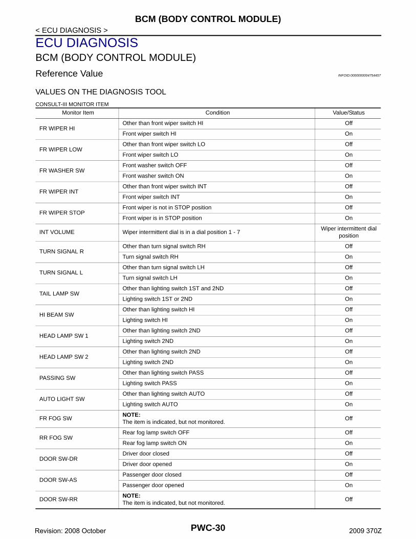
Reference Value INFOID:0000000004754457
VALUES ON THE DIAGNOSIS TOOL
CONSULT-III MONITOR ITEM
Monitor Item Condition Value/Status
FR WIPER HIOther than front wiper switch HI Off
Front wiper switch HI On
FR WIPER LOWOther than front wiper switch LO Off
Front wiper switch LO On
FR WASHER SWFront washer switch OFF Off
Front washer switch ON On
FR WIPER INTOther than front wiper switch INT Off
Front wiper switch INT On
FR WIPER STOPFront wiper is not in STOP position Off
Front wiper is in STOP position On
INT VOLUME Wiper intermittent dial is in a dial position 1 - 7Wiper intermittent dial
position
TURN SIGNAL ROther than turn signal switch RH Off
Turn signal switch RH On
TURN SIGNAL LOther than turn signal switch LH Off
Turn signal switch LH On
TAIL LAMP SWOther than lighting switch 1ST and 2ND Off
Lighting switch 1ST or 2ND On
HI BEAM SWOther than lighting switch HI Off
Lighting switch HI On
HEAD LAMP SW 1Other than lighting switch 2ND Off
Lighting switch 2ND On
HEAD LAMP SW 2Other than lighting switch 2ND Off
Lighting switch 2ND On
PASSING SWOther than lighting switch PASS Off
Lighting switch PASS On
AUTO LIGHT SWOther than lighting switch AUTO Off
Lighting switch AUTO On
FR FOG SWNOTE:The item is indicated, but not monitored.
Off
RR FOG SWRear fog lamp switch OFF Off
Rear fog lamp switch ON On
DOOR SW-DRDriver door closed Off
Driver door opened On
DOOR SW-ASPassenger door closed Off
Passenger door opened On
DOOR SW-RRNOTE:The item is indicated, but not monitored.
Off
PWC-30Revision: 2008 October 2009 370Z

BCM (BODY CONTROL MODULE)
C
D
E
F
G
H
I
J
L
M
A
B
WC
N
O
P
< ECU DIAGNOSIS >
P
DOOR SW-RLNOTE:The item is indicated, but not monitored.
Off
DOOR SW-BKBack door closed Off
Back door opened On
CDL LOCK SWOther than door lock and unlock switch LOCK Off
Door lock and unlock switch LOCK On
CDL UNLOCK SWOther than door lock and unlock switch UNLOCK Off
Door lock and unlock switch UNLOCK On
KEY CYL LK-SWOther than driver door key cylinder LOCK position Off
Driver door key cylinder LOCK position On
KEY CYL UN-SWOther than driver door key cylinder UNLOCK position Off
Driver door key cylinder UNLOCK position On
KEY CYL SW-TRNOTE:The item is indicated, but not monitored.
Off
HAZARD SWHazard switch is OFF Off
Hazard switch is ON On
REAR DEF SWNOTE:At models with NAVI this item is not monitored.
Rear window defogger switch OFF Off
Rear window defogger switch ON On
H/L WASH SWNOTE:The item is indicated, but not monitored.
Off
TR CANCEL SWNOTE:The item is indicated, but not monitored.
Off
TR/BD OPEN SWBack door opener switch OFF Off
While the back door opener switch is turned ON On
TRNK/HAT MNTRNOTE:The item is indicated, but not monitored.
Off
RKE-LOCKLOCK button of the Intelligent Key is not pressed Off
LOCK button of the Intelligent Key is pressed On
RKE-UNLOCKUNLOCK button of the Intelligent Key is not pressed Off
UNLOCK button of the Intelligent Key is pressed On
RKE-TR/BDNOTE:The item is indicated, but not monitored.
Off
RKE-PANICPANIC button of the Intelligent Key is not pressed Off
PANIC button of the Intelligent Key is pressed On
RKE-P/W OPENUNLOCK button of the Intelligent Key is not pressed Off
UNLOCK button of the Intelligent Key is pressed and held On
RKE-MODE CHG
LOCK/UNLOCK button of the Intelligent Key is not pressed and held simul-taneously
Off
LOCK/UNLOCK button of the Intelligent Key is pressed and held simulta-neously
On
OPTICAL SENSORBright outside of the vehicle Close to 5 V
Dark outside of the vehicle Close to 0 V
REQ SW -DRDriver door request switch is not pressed Off
Driver door request switch is pressed On
REQ SW -ASPassenger door request switch is not pressed Off
Passenger door request switch is pressed On
Monitor Item Condition Value/Status
PWC-31Revision: 2008 October 2009 370Z
BCM (BODY CONTROL MODULE)
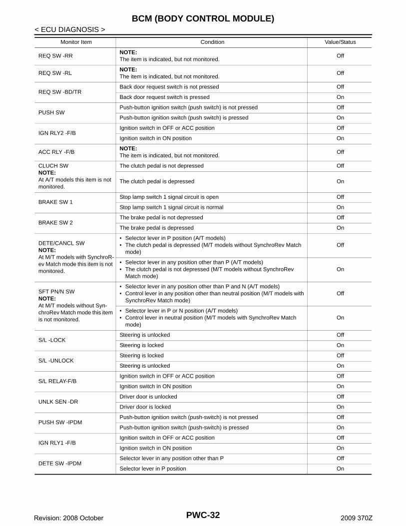
< ECU DIAGNOSIS >REQ SW -RRNOTE:The item is indicated, but not monitored.
Off
REQ SW -RLNOTE:The item is indicated, but not monitored.
Off
REQ SW -BD/TRBack door request switch is not pressed Off
Back door request switch is pressed On
PUSH SWPush-button ignition switch (push switch) is not pressed Off
Push-button ignition switch (push switch) is pressed On
IGN RLY2 -F/BIgnition switch in OFF or ACC position Off
Ignition switch in ON position On
ACC RLY -F/BNOTE:The item is indicated, but not monitored.
Off
CLUCH SWNOTE:At A/T models this item is not monitored.
The clutch pedal is not depressed Off
The clutch pedal is depressed On
BRAKE SW 1Stop lamp switch 1 signal circuit is open Off
Stop lamp switch 1 signal circuit is normal On
BRAKE SW 2The brake pedal is not depressed Off
The brake pedal is depressed On
DETE/CANCL SWNOTE:At M/T models with SynchroR-ev Match mode this item is not monitored.
• Selector lever in P position (A/T models)• The clutch pedal is depressed (M/T models without SynchroRev Match
mode)Off
• Selector lever in any position other than P (A/T models)• The clutch pedal is not depressed (M/T models without SynchroRev
Match mode)On
SFT PN/N SWNOTE:At M/T models without Syn-chroRev Match mode this item is not monitored.
• Selector lever in any position other than P and N (A/T models)• Control lever in any position other than neutral position (M/T models with
SynchroRev Match mode)Off
• Selector lever in P or N position (A/T models)• Control lever in neutral position (M/T models with SynchroRev Match
mode)On
S/L -LOCKSteering is unlocked Off
Steering is locked On
S/L -UNLOCKSteering is locked Off
Steering is unlocked On
S/L RELAY-F/BIgnition switch in OFF or ACC position Off
Ignition switch in ON position On
UNLK SEN -DRDriver door is unlocked Off
Driver door is locked On
PUSH SW -IPDMPush-button ignition switch (push-switch) is not pressed Off
Push-button ignition switch (push-switch) is pressed On
IGN RLY1 -F/BIgnition switch in OFF or ACC position Off
Ignition switch in ON position On
DETE SW -IPDMSelector lever in any position other than P Off
Selector lever in P position On
Monitor Item Condition Value/Status
PWC-32Revision: 2008 October 2009 370Z

BCM (BODY CONTROL MODULE)
C
D
E
F
G
H
I
J
L
M
A
B
WC
N
O
P
< ECU DIAGNOSIS >
P
SFT PN -IPDM
• Selector lever in any position other than P and N (A/T models)• The clutch pedal is not depressed (M/T models)
Off
• Selector lever in P or N position (A/T models)• The clutch pedal is depressed (M/T models)
On
SFT P -METSelector lever in any position other than P Off
Selector lever in P position On
SFT N -METSelector lever in any position other than N Off
Selector lever in N position On
ENGINE STATE
Engine stopped Stop
While the engine stalls Stall
At engine cranking Crank
Engine running Run
S/L LOCK-IPDMSteering is unlocked Off
Steering is locked On
S/L UNLK-IPDMSteering is locked Off
Steering is unlocked On
S/L RELAY-REQ
Steering lock system is not the LOCK condition and the changing condition from LOCK to UNLOCK
Off
Steering lock system are not the LOCK condition or the changing condition from LOCK to UNLOCK
On
VEH SPEED 1 While drivingEquivalent to speedom-
eter reading
VEH SPEED 2 While drivingEquivalent to speedom-
eter reading
DOOR STAT-DR
Driver door is locked LOCK
Wait with selective UNLOCK operation (60 seconds) READY
Driver door is unlocked UNLOCK
DOOR STAT-AS
Passenger door is locked LOCK
Wait with selective UNLOCK operation (60 seconds) READY
Passenger door is unlocked UNLOCK
ID OK FLAGSteering is locked Reset
Steering is unlocked Set
PRMT ENG STRTThe engine start is prohibited Reset
The engine start is permitted Set
PRMT RKE STRTNOTE:The item is indicated, but not monitored.
Reset
KEY SW -SLOTThe Intelligent Key is not inserted into key slot Off
The Intelligent Key is inserted into key slot On
RKE OPE COUN1 During the operation of the Intelligent KeyOperation frequency of
the Intelligent Key
RKE OPE COUN2NOTE:The item is indicated, but not monitored.
—
CONFRM ID ALL
The key ID that the key slot receives is not recognized by any key ID regis-tered to BCM.
Yet
The key ID that the key slot receives is recognized by any key ID registered to BCM.
Done
Monitor Item Condition Value/Status
PWC-33Revision: 2008 October 2009 370Z
BCM (BODY CONTROL MODULE)
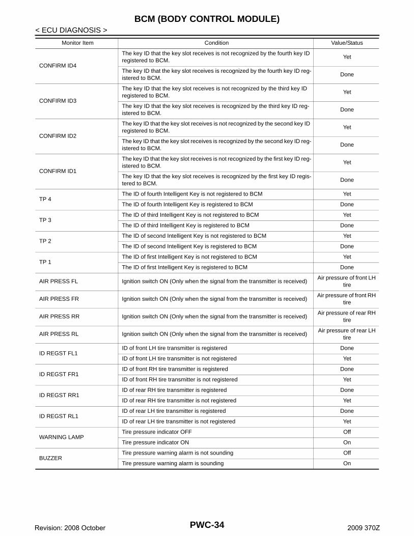
< ECU DIAGNOSIS >CONFIRM ID4
The key ID that the key slot receives is not recognized by the fourth key ID registered to BCM.
Yet
The key ID that the key slot receives is recognized by the fourth key ID reg-istered to BCM.
Done
CONFIRM ID3
The key ID that the key slot receives is not recognized by the third key ID registered to BCM.
Yet
The key ID that the key slot receives is recognized by the third key ID reg-istered to BCM.
Done
CONFIRM ID2
The key ID that the key slot receives is not recognized by the second key ID registered to BCM.
Yet
The key ID that the key slot receives is recognized by the second key ID reg-istered to BCM.
Done
CONFIRM ID1
The key ID that the key slot receives is not recognized by the first key ID reg-istered to BCM.
Yet
The key ID that the key slot receives is recognized by the first key ID regis-tered to BCM.
Done
TP 4The ID of fourth Intelligent Key is not registered to BCM Yet
The ID of fourth Intelligent Key is registered to BCM Done
TP 3The ID of third Intelligent Key is not registered to BCM Yet
The ID of third Intelligent Key is registered to BCM Done
TP 2The ID of second Intelligent Key is not registered to BCM Yet
The ID of second Intelligent Key is registered to BCM Done
TP 1The ID of first Intelligent Key is not registered to BCM Yet
The ID of first Intelligent Key is registered to BCM Done
AIR PRESS FL Ignition switch ON (Only when the signal from the transmitter is received)Air pressure of front LH
tire
AIR PRESS FR Ignition switch ON (Only when the signal from the transmitter is received)Air pressure of front RH
tire
AIR PRESS RR Ignition switch ON (Only when the signal from the transmitter is received)Air pressure of rear RH
tire
AIR PRESS RL Ignition switch ON (Only when the signal from the transmitter is received)Air pressure of rear LH
tire
ID REGST FL1ID of front LH tire transmitter is registered Done
ID of front LH tire transmitter is not registered Yet
ID REGST FR1ID of front RH tire transmitter is registered Done
ID of front RH tire transmitter is not registered Yet
ID REGST RR1ID of rear RH tire transmitter is registered Done
ID of rear RH tire transmitter is not registered Yet
ID REGST RL1ID of rear LH tire transmitter is registered Done
ID of rear LH tire transmitter is not registered Yet
WARNING LAMPTire pressure indicator OFF Off
Tire pressure indicator ON On
BUZZERTire pressure warning alarm is not sounding Off
Tire pressure warning alarm is sounding On
Monitor Item Condition Value/Status
PWC-34Revision: 2008 October 2009 370Z

BCM (BODY CONTROL MODULE)
C
D
E
F
G
H
I
J
L
M
A
B
WC
N
O
P
< ECU DIAGNOSIS >
P
TERMINAL LAYOUT
PHYSICAL VALUES
JPMIA0062ZZ
PWC-35Revision: 2008 October 2009 370Z

BCM (BODY CONTROL MODULE)
< ECU DIAGNOSIS >Terminal No.(Wire color)
Description
ConditionValue
(Approx.)Signal nameInput/ Output+ –
1(W)
Ground Battery power supply Input Ignition switch OFF Battery voltage
2(W)
GroundP/W power supply (BAT)
Output Ignition switch OFF 12 V
3(Y)
GroundP/W power supply (RAP)
Output Ignition switch ON 12 V
4(R)
GroundInterior room lamp power supply
Output
Interior room lamp battery saver is activated.(Cuts the interior room lamp power supply)
0 V
Interior room lamp battery saver is not acti-vated.(Outputs the interior room lamp power sup-ply)
12 V
5(G)
GroundPassenger door UN-LOCK
OutputPassenger door
UNLOCK (Actuator is acti-vated)
12 V
Other than UNLOCK (Ac-tuator is not activated)
0 V
8(V)
GroundAll doors, fuel lid LOCK
OutputAll doors, fuel lid
LOCK(Actuator is activated)
12 V
Other than LOCK(Actuator is not activated)
0 V
9(G)
GroundDriver door, fuel lid UNLOCK
OutputDriver door, fuel lid
UNLOCK(Actuator is activated)
12 V
Other than UNLOCK(Actuator is not activated)
0 V
11(BR)
Ground Battery power supply Input Ignition switch OFF Battery voltage
13(B)
Ground Ground — Ignition switch ON 0 V
14(R)
GroundPush-button ignition switch illumination ground
Output Tail lamp
OFF 0 V
ON
NOTE:When the illumination brighten-
ing/dimming level is in the neutral position.
15(Y)
Ground ACC indicator lamp Output Ignition switch
OFF (LOCK indicator is not illuminated)
Battery voltage
ACC 0 V
JSNIA0010GB
PWC-36Revision: 2008 October 2009 370Z

BCM (BODY CONTROL MODULE)
C
D
E
F
G
H
I
J
L
M
A
B
WC
N
O
P
< ECU DIAGNOSIS >
P
17(W)
GroundTurn signal RH (Front and side)
OutputIgnition switch ON
Turn signal switch OFF 0 V
Turn signal switch RH
6.5 V
18(O)
GroundTurn signal LH (Front and side)
OutputIgnition switch ON
Turn signal switch OFF 0 V
Turn signal switch LH
6.5 V
19(V)
GroundRoom lamp timer control
OutputInterior room lamp
OFF 12 V
ON 0 V
20(V)
Ground Turn signal RH (Rear) OutputIgnition switch ON
Turn signal switch OFF 0 V
Turn signal switch RH
6.5 V
23(L)
Ground Back door open Output Back door
OPEN(Back door opener actua-tor is activated)
12 V
Other than OPEN(Back door opener actua-tor is not activated)
0 V
24*1
(O)Ground Rear fog lamp Output Rear fog lamp
OFF 0 V
ON 12 V
25(LG)
Ground Turn signal LH (Rear) OutputIgnition switch ON
Turn signal switch OFF 0 V
Turn signal switch LH
6.5 V
30(R)
Ground Luggage room lamp OutputLuggage room lamp
ON 0 V
OFF 12 V
Terminal No.(Wire color)
Description
ConditionValue
(Approx.)Signal nameInput/ Output+ –
PKID0926E
PKID0926E
PKID0926E
PKID0926E
PWC-37Revision: 2008 October 2009 370Z

BCM (BODY CONTROL MODULE)
< ECU DIAGNOSIS >34(G)
GroundLuggage room anten-na (−)
OutputIgnition switch OFF
When Intelligent Key is in the passenger compart-ment
When Intelligent Key is not in the passenger compart-ment
35(R)
GroundLuggage room anten-na (+)
OutputIgnition switch OFF
When Intelligent Key is in the passenger compart-ment
When Intelligent Key is not in the passenger compart-ment
38(B)
GroundRear bumper anten-na (−)
Output
When the back door request switch is oper-ated with igni-tion switch OFF
When Intelligent Key is in the antenna detection area
When Intelligent Key is not in the antenna detection area
Terminal No.(Wire color)
Description
ConditionValue
(Approx.)Signal nameInput/ Output+ –
JMKIA0062GB
JMKIA0063GB
JMKIA0062GB
JMKIA0063GB
JMKIA0062GB
JMKIA0063GB
PWC-38Revision: 2008 October 2009 370Z

BCM (BODY CONTROL MODULE)
C
D
E
F
G
H
I
J
L
M
A
B
WC
N
O
P
< ECU DIAGNOSIS >
P
39(W)
GroundRear bumper anten-na (+)
Output
When the back door request switch is oper-ated with igni-tion switch OFF
When Intelligent Key is in the antenna detection area
When Intelligent Key is not in the antenna detection area
47(V)
GroundIgnition relay (IPDM E/R) control
Output Ignition switchOFF or ACC 12 V
ON 0 V
52(SB)
Ground Starter relay control Output
Ignition switch ON (A/T mod-els)
When selector lever is in P or N position
12 V
When selector lever is not in P or N position
0 V
Ignition switch ON (M/T mod-els)
When the clutch pedal is depressed
Battery voltage
When the clutch pedal is not depressed
0 V
61(W)
GroundBack door request switch
InputBack door re-quest switch
ON (Pressed) 0 V
OFF (Not pressed)
1.0 V
64(G)
GroundIntelligent Key warn-ing buzzer
OutputIntelligent Key warning buzzer
Sounding 0 V
Not sounding 12 V
66(R)
Ground Back door switch InputBack door switch
OFF (Door close)
11.8 V
ON (Door open) 0 V
Terminal No.(Wire color)
Description
ConditionValue
(Approx.)Signal nameInput/ Output+ –
JMKIA0062GB
JMKIA0063GB
JPMIA0016GB
JPMIA0011GB
PWC-39Revision: 2008 October 2009 370Z
BCM (BODY CONTROL MODULE)
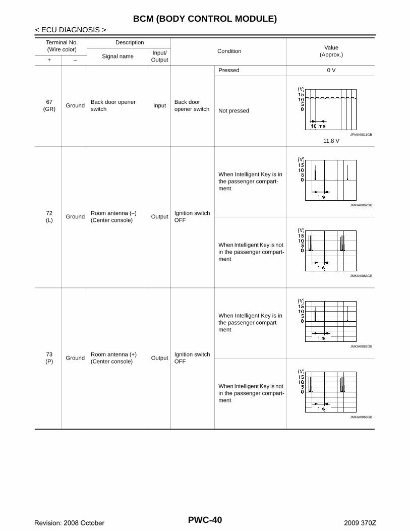
< ECU DIAGNOSIS >67(GR)
GroundBack door opener switch
InputBack door opener switch
Pressed 0 V
Not pressed
11.8 V
72(L)
GroundRoom antenna (−) (Center console)
OutputIgnition switch OFF
When Intelligent Key is in the passenger compart-ment
When Intelligent Key is not in the passenger compart-ment
73(P)
GroundRoom antenna (+) (Center console)
OutputIgnition switch OFF
When Intelligent Key is in the passenger compart-ment
When Intelligent Key is not in the passenger compart-ment
Terminal No.(Wire color)
Description
ConditionValue
(Approx.)Signal nameInput/ Output+ –
JPMIA0011GB
JMKIA0062GB
JMKIA0063GB
JMKIA0062GB
JMKIA0063GB
PWC-40Revision: 2008 October 2009 370Z

BCM (BODY CONTROL MODULE)
C
D
E
F
G
H
I
J
L
M
A
B
WC
N
O
P
< ECU DIAGNOSIS >
P
74(SB)
GroundPassenger door an-tenna (−)
Output
When the pas-senger door re-quest switch is operated with ignition switch OFF
When Intelligent Key is in the antenna detection area
When Intelligent Key is not in the antenna detection area
75(BR)
GroundPassenger door an-tenna (+)
Output
When the pas-senger door re-quest switch is operated with ignition switch OFF
When Intelligent Key is in the antenna detection area
When Intelligent Key is not in the antenna detection area
76(V)
GroundDriver door antenna (−)
Output
When the driv-er door request switch is oper-ated with igni-tion switch OFF
When Intelligent Key is in the antenna detection area
When Intelligent Key is not in the antenna detection area
Terminal No.(Wire color)
Description
ConditionValue
(Approx.)Signal nameInput/ Output+ –
JMKIA0062GB
JMKIA0063GB
JMKIA0062GB
JMKIA0063GB
JMKIA0062GB
JMKIA0063GB
PWC-41Revision: 2008 October 2009 370Z

BCM (BODY CONTROL MODULE)
< ECU DIAGNOSIS >77(LG)
GroundDriver door antenna (+)
Output
When the driv-er door request switch is oper-ated with igni-tion switch OFF
When Intelligent Key is in the antenna detection area
When Intelligent Key is not in the antenna detection area
80(GR)
GroundNATS antenna amp (Built in key slot)
Input/Output
During waitingIgnition switch is pressed while inserting the Intelli-gent Key into the key slot.
Just after pressing ignition switch. Pointer of tester should
move.
81(W)
GroundNATS antenna amp (Built in key slot)
Input/Output
During waitingIgnition switch is pressed while inserting the Intelli-gent Key into the key slot.
Just after pressing ignition switch. Pointer of tester should
move.
82(R)
GroundIgnition relay [Fuse block (J/B)] control
Output Ignition switchOFF or ACC 0 V
ON 12 V
83(GR)
GroundRemote keyless entry receiver communica-tion
Input/Output
During waiting
When operating either button on the Intelli-gent Key
Terminal No.(Wire color)
Description
ConditionValue
(Approx.)Signal nameInput/ Output+ –
JMKIA0062GB
JMKIA0063GB
JMKIA0064GB
JMKIA0065GB
PWC-42Revision: 2008 October 2009 370Z

BCM (BODY CONTROL MODULE)
C
D
E
F
G
H
I
J
L
M
A
B
WC
N
O
P
< ECU DIAGNOSIS >
P
87(BR)
GroundCombination switch INPUT 5
InputCombination switch
All switches OFF(Wiper intermittent dial 4)
1.4 V
Rear fog lamp switch ON(Wiper intermittent dial 4)
1.3 V
Any of the conditions be-low with all switches OFF• Wiper intermittent dial 1• Wiper intermittent dial 2• Wiper intermittent dial 6• Wiper intermittent dial 7
1.3 V
Terminal No.(Wire color)
Description
ConditionValue
(Approx.)Signal nameInput/ Output+ –
JPMIA0041GB
JPMIA0038GB
JPMIA0040GB
PWC-43Revision: 2008 October 2009 370Z

BCM (BODY CONTROL MODULE)
< ECU DIAGNOSIS >88(V)
GroundCombination switch INPUT 3
InputCombination switch
All switches OFF(Wiper intermittent dial 4)
1.4 V
Lighting switch HI(Wiper intermittent dial 4)
1.3 V
Lighting switch 2ND(Wiper intermittent dial 4)
1.3 V
Any of the conditions be-low with all switches OFF• Wiper intermittent dial 1• Wiper intermittent dial 2• Wiper intermittent dial 3
1.3 V
89(BR)
GroundPush-button ignition switch (Push switch)
InputPush-button ig-nition switch (push switch)
Pressed 0 V
Not pressed Battery voltage
90(P)
Ground CAN-LInput/ Output
— —
91(L)
Ground CAN-HInput/ Output
— —
92(LG)
Ground Key slot illumination OutputKey slot illumi-nation
OFF 0 V
Blinking
6.5 V
ON 12 V
Terminal No.(Wire color)
Description
ConditionValue
(Approx.)Signal nameInput/ Output+ –
JPMIA0041GB
JPMIA0036GB
JPMIA0037GB
JPMIA0040GB
JPMIA0015GB
PWC-44Revision: 2008 October 2009 370Z
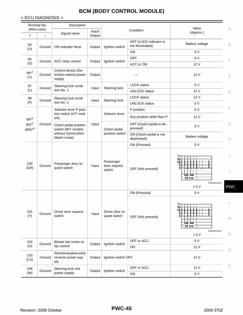
BCM (BODY CONTROL MODULE)
C
D
E
F
G
H
I
J
L
M
A
B
WC
N
O
P
< ECU DIAGNOSIS >
P
93(V)
Ground ON indicator lamp Output Ignition switch
OFF (LOCK indicator is not illuminated)
Battery voltage
ON 0 V
95(O)
Ground ACC relay control Output Ignition switchOFF 0 V
ACC or ON 12 V
96*2
(Y)Ground
Control device (De-tention switch) power supply
Output — 12 V
97(L)
GroundSteering lock condi-tion No. 1
Input Steering lockLOCK status 0 V
UNLOCK status 12 V
98(P)
GroundSteering lock condi-tion No. 2
Input Steering lockLOCK status 12 V
UNLOCK status 0 V
99*3
(R)*2
(BR)*4
Ground
Selector lever P posi-tion switch (A/T mod-els)
Input
Selector leverP position 0 V
Any position other than P 12 V
Clutch pedal position switch (M/T models without SynchroRev Match mode)
Clutch pedal position switch
OFF (Clutch pedal is de-pressed)
0 V
ON (Clutch pedal is not depressed)
Battery voltage
100(GR)
GroundPassenger door re-quest switch
InputPassenger door request switch
ON (Pressed) 0 V
OFF (Not pressed)
1.0 V
101(Y)
GroundDriver door request switch
InputDriver door re-quest switch
ON (Pressed) 0 V
OFF (Not pressed)
1.0 V
102(O)
GroundBlower fan motor re-lay control
Output Ignition switchOFF or ACC 0 V
ON 12 V
103(LG)
GroundRemote keyless entry receiver power sup-ply
Output Ignition switch OFF 12 V
106(W)
GroundSteering lock unit power supply
Output Ignition switchOFF or ACC 12 V
ON 0 V
Terminal No.(Wire color)
Description
ConditionValue
(Approx.)Signal nameInput/ Output+ –
JPMIA0016GB
JPMIA0016GB
PWC-45Revision: 2008 October 2009 370Z

BCM (BODY CONTROL MODULE)
< ECU DIAGNOSIS >107(LG)
GroundCombination switch INPUT 1
Input
Combination switch(Wiper intermit-tent dial 4)
All switches OFF
1.4 V
Turn signal switch LH
1.3 V
Turn signal switch RH
1.3 V
Front wiper switch LO
1.3 V
Front washer switch ON
1.3 V
Terminal No.(Wire color)
Description
ConditionValue
(Approx.)Signal nameInput/ Output+ –
JPMIA0041GB
JPMIA0037GB
JPMIA0036GB
JPMIA0038GB
JPMIA0039GB
PWC-46Revision: 2008 October 2009 370Z
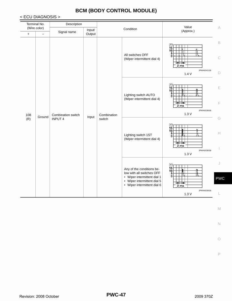
BCM (BODY CONTROL MODULE)
C
D
E
F
G
H
I
J
L
M
A
B
WC
N
O
P
< ECU DIAGNOSIS >
P
108(R)
GroundCombination switch INPUT 4
InputCombination switch
All switches OFF(Wiper intermittent dial 4)
1.4 V
Lighting switch AUTO(Wiper intermittent dial 4)
1.3 V
Lighting switch 1ST(Wiper intermittent dial 4)
1.3 V
Any of the conditions be-low with all switches OFF• Wiper intermittent dial 1• Wiper intermittent dial 5• Wiper intermittent dial 6
1.3 V
Terminal No.(Wire color)
Description
ConditionValue
(Approx.)Signal nameInput/ Output+ –
JPMIA0041GB
JPMIA0038GB
JPMIA0036GB
JPMIA0039GB
PWC-47Revision: 2008 October 2009 370Z

BCM (BODY CONTROL MODULE)
< ECU DIAGNOSIS >109(Y)
GroundCombination switch INPUT 2
Input
Combination switch(Wiper intermit-tent dial 4)
All switches OFF
1.4 V
Lighting switch PASS
1.3 V
Lighting switch 2ND
1.3 V
Front wiper switch INT
1.3 V
Front wiper switch HI
1.3 V
110(P)
Ground Hazard switch Input Hazard switch
ON 0 V
OFF
1.1 V
Terminal No.(Wire color)
Description
ConditionValue
(Approx.)Signal nameInput/ Output+ –
JPMIA0041GB
JPMIA0037GB
JPMIA0036GB
JPMIA0038GB
JPMIA0040GB
JPMIA0012GB
PWC-48Revision: 2008 October 2009 370Z

BCM (BODY CONTROL MODULE)
C
D
E
F
G
H
I
J
L
M
A
B
WC
N
O
P
< ECU DIAGNOSIS >
P
111(Y)
GroundSteering lock unit communication
Input/Output
Steering lock
LOCK status 12 V
LOCK or UNLOCK
For 15 seconds after UN-LOCK
12 V
15 seconds or later after UNLOCK
0 V
113(O)
Ground Optical sensor InputIgnition switch ON
When bright outside of the vehicle
Close to 5 V
When dark outside of the vehicle
Close to 0 V
114*5
(R)Ground
Clutch interlock switch
InputClutch interlock switch
OFF (Clutch pedal is not depressed)
0 V
ON (Clutch pedal is de-pressed)
Battery voltage
116(SB)
Ground Stop lamp switch 1 Input — Battery voltage
118(P)
Ground Stop lamp switch 2 InputStop lamp switch
OFF (Brake pedal is not depressed)
0 V
ON (Brake pedal is de-pressed)
Battery voltage
119(SB)
GroundDriver side door lock assembly (Unlock sensor)
Input Driver door
LOCK status(Unlock sensor switch OFF)
1.1 V
UNLOCK status(Unlock switch sensor ON)
0 V
121(R)
Ground Key slot switch Input
When the Intelligent Key is inserted into key slot
12 V
When the Intelligent Key is not inserted into key slot
0 V
123(W)
Ground IGN feedback Input Ignition switchOFF or ACC 0 V
ON Battery voltage
Terminal No.(Wire color)
Description
ConditionValue
(Approx.)Signal nameInput/ Output+ –
JMKIA0066GB
JPMIA0012GB
PWC-49Revision: 2008 October 2009 370Z
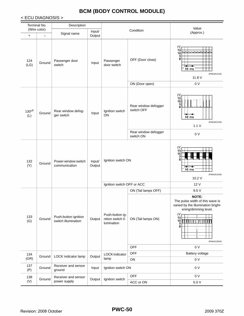
BCM (BODY CONTROL MODULE)
< ECU DIAGNOSIS >124(LG)
GroundPassenger door switch
InputPassenger door switch
OFF (Door close)
11.8 V
ON (Door open) 0 V
130*6
(L)Ground
Rear window defog-ger switch
InputIgnition switch ON
Rear window defogger switch OFF
1.1 V
Rear window defogger switch ON
0 V
132(Y)
GroundPower window switch communication
Input/Output
Ignition switch ON
10.2 V
Ignition switch OFF or ACC 12 V
133(G)
GroundPush-button ignition switch illumination
OutputPush-button ig-nition switch il-lumination
ON (Tail lamps OFF) 9.5 V
ON (Tail lamps ON)
NOTE:The pulse width of this wave is
varied by the illumination bright-ening/dimming level.
OFF 0 V
134(GR)
Ground LOCK indicator lamp OutputLOCK indicator lamp
OFF Battery voltage
ON 0 V
137(P)
GroundReceiver and sensor ground
Input Ignition switch ON 0 V
138(V)
GroundReceiver and sensor power supply
Output Ignition switchOFF 0 V
ACC or ON 5.0 V
Terminal No.(Wire color)
Description
ConditionValue
(Approx.)Signal nameInput/ Output+ –
JPMIA0011GB
JPMIA0012GB
JPMIA0013GB
JPMIA0159GB
PWC-50Revision: 2008 October 2009 370Z

BCM (BODY CONTROL MODULE)
C
D
E
F
G
H
I
J
L
M
A
B
WC
N
O
P
< ECU DIAGNOSIS >
P
139(L)
GroundTire pressure receiv-er communication
Input/Output
Ignition switch ON
Standby state
When receiving the signal from the transmitter
140*7
(G)Ground
Selector lever P/N position (A/T models)
Input
Selector leverP or N position 12 V
Except P and N positions 0 V
Park/neutral position switch (M/T models with SynchroRev Match mode)
Ignition switch ON
Control lever in neutral po-sition
Battery voltage
Control lever in any posi-tion other than neutral
0 V
141(Y)
Ground Security indicator OutputSecurity indica-tor
ON 0 V
Blinking
11.3 V
OFF 12 V
142(O)
GroundCombination switch OUTPUT 5
Output
Combination switch(Wiper intermit-tent dial 4)
All switches OFF 0 V
Lighting switch 1ST
10.7 V
Lighting switch HI
Lighting switch 2ND
Turn signal switch RH
143(P)
GroundCombination switch OUTPUT 1
OutputCombination switch
All switches OFF(Wiper intermittent dial 4)
0 V
Front wiper switch HI(Wiper intermittent dial 4)
10.7 V
Any of the conditions be-low with all switches OFF• Wiper intermittent dial 1• Wiper intermittent dial 2• Wiper intermittent dial 3• Wiper intermittent dial 6• Wiper intermittent dial 7
Terminal No.(Wire color)
Description
ConditionValue
(Approx.)Signal nameInput/ Output+ –
OCC3881D
OCC3880D
JPMIA0014GB
JPMIA0031GB
JPMIA0032GB
PWC-51Revision: 2008 October 2009 370Z

BCM (BODY CONTROL MODULE)
< ECU DIAGNOSIS >• *1: For Canada
• *2: A/T models
• *3: Except M/T models with SynchroRev Match mode
• *4: M/T models without SynchroRev Match mode
• *5: M/T models
• *6: Without NAVI
• *7: Except M/T models without SynchroRev Match mode
144(G)
GroundCombination switch OUTPUT 2
OutputCombination switch
All switches OFF(Wiper intermittent dial 4)
0 V
Front washer switch ON(Wiper intermittent dial 4)
10.7 V
Any of the conditions be-low with all switches OFF• Wiper intermittent dial 1• Wiper intermittent dial 5• Wiper intermittent dial 6
145(L)
GroundCombination switch OUTPUT 3
Output
Combination switch(Wiper intermit-tent dial 4)
All switches OFF 0 V
Front wiper switch INT
10.7 V
Front wiper switch LO
Lighting switch AUTO
Rear fog lamp switch ON
146(SB)
GroundCombination switch OUTPUT 4
Output
Combination switch(Wiper intermit-tent dial 4)
All switches OFF 0 V
Lighting switch 2ND
10.7 V
Lighting switch PASS
Turn signal switch LH
149(W)
GroundTire pressure warning check switch
Input — 12 V
150(GR)
Ground Driver door switch InputDriver door switch
OFF (Door close)
11.8 V
ON (Door open) 0 V
151(G)
GroundRear window defog-ger relay control
OutputRear window defogger
Active 0 V
Not activated Battery voltage
Terminal No.(Wire color)
Description
ConditionValue
(Approx.)Signal nameInput/ Output+ –
JPMIA0033GB
JPMIA0034GB
JPMIA0035GB
JPMIA0011GB
PWC-52Revision: 2008 October 2009 370Z

BCM (BODY CONTROL MODULE)
C
D
E
F
G
H
I
J
L
M
A
B
WC
N
O
P
< ECU DIAGNOSIS >
P
Wiring Diagram - BCM - INFOID:0000000004754458
JCMWA3235GB
PWC-53Revision: 2008 October 2009 370Z

BCM (BODY CONTROL MODULE)
< ECU DIAGNOSIS >JCMWA3236GB
PWC-54Revision: 2008 October 2009 370Z

BCM (BODY CONTROL MODULE)
C
D
E
F
G
H
I
J
L
M
A
B
WC
N
O
P
< ECU DIAGNOSIS >
P
JCMWA3237GB
PWC-55Revision: 2008 October 2009 370Z

BCM (BODY CONTROL MODULE)
< ECU DIAGNOSIS >JCMWA3238GB
PWC-56Revision: 2008 October 2009 370Z

BCM (BODY CONTROL MODULE)
C
D
E
F
G
H
I
J
L
M
A
B
WC
N
O
P
< ECU DIAGNOSIS >
P
JCMWA3239GB
PWC-57Revision: 2008 October 2009 370Z

BCM (BODY CONTROL MODULE)
< ECU DIAGNOSIS >Fail-safe INFOID:0000000004754459
FAIL-SAFE CONTROL BY DTCBCM performs fail-safe control when any DTC are detected.
JCMWA3240GB
PWC-58Revision: 2008 October 2009 370Z

BCM (BODY CONTROL MODULE)
C
D
E
F
G
H
I
J
L
M
A
B
WC
N
O
P
< ECU DIAGNOSIS >
P
Display contents of CONSULT Fail-safe Cancellation
B2013: ID DISCORD BCM-S/L Inhibit engine cranking Erase DTC
B2014: CHAIN OF S/L-BCM Inhibit engine cranking Erase DTC
B2190: NATS ANTENNA AMP Inhibit engine cranking Erase DTC
B2191: DIFFERENCE OF KEY Inhibit engine cranking Erase DTC
B2192: ID DISCORD BCM-ECM Inhibit engine cranking Erase DTC
B2193: CHAIN OF BCM-ECM Inhibit engine cranking Erase DTC
B2195: ANTI SCANNING Inhibit engine cranking Ignition switch ON → OFF
B2557: VEHICLE SPEED Inhibit steering lockWhen normal vehicle speed signals are received from ABS actua-tor and electric unit (control unit) for 500 ms
B2560: STARTER CONT RELAY Inhibit engine cranking
500 ms after the following CAN signal communication status be-comes consistent• Starter control relay signal• Starter relay status signal
B2601: SHIFT POSITION Inhibit steering lock
500 ms after the following signal reception status becomes consis-tent• Selector lever P position switch signal• P range signal (CAN)
B2602: SHIFT POSITION Inhibit steering lock
5 seconds after the following BCM recognition conditions are ful-filled• Ignition switch is in the ON position• Selector lever P position switch signal: Except P position (battery
voltage)• Vehicle speed: 4 km/h (2.5 MPH) or more
B2603: SHIFT POSI STATUS Inhibit steering lock
500 ms after the following BCM recognition conditions are fulfilled• Ignition switch is in the ON position• Selector lever P position switch signal: Except P position (battery
voltage)• Selector lever P/N position signal: Except P and N positions (0 V)
B2604: PNP SW Inhibit steering lock
500 ms after any of the following BCM recognition conditions are fulfilled• Status 1- Ignition switch is in the ON position- Selector lever P/N position signal: P and N position (battery volt-
age)- P range signal or N range signal (CAN): ON• Status 2- Ignition switch is in the ON position- Selector lever P/N position signal: Except P and N positions (0 V)- P range signal and N range signal (CAN): OFF
B2605: PNP SW Inhibit steering lock
500 ms after any of the following BCM recognition conditions are fulfilled• Status 1- Ignition switch is in the ON position- Selector lever P/N position signal: Except P and N positions (0 V)- Interlock/PNP switch signal (CAN): OFF• Status 2- Ignition switch is in the ON position- Selector lever P/N position signal: P or N position (battery volt-
age)- PNP switch signal (CAN): ON
B2606: S/L RELAY Inhibit engine cranking
500 ms after the following CAN signal communication status be-comes consistent• Steering lock relay signal (Request signal)• Steering lock relay signal (Condition signal)
PWC-59Revision: 2008 October 2009 370Z

BCM (BODY CONTROL MODULE)
< ECU DIAGNOSIS >HIGH FLASHER OPERATIONBCM detects the turn signal lamp circuit status by the current value.BCM increases the turn signal lamp blinking speed if the bulb or harness open is detected with the turn signallamp operating.NOTE:The blinking speed is normal while activating the hazard warning lamp.
FAIL-SAFE CONTROL BY RAIN SENSOR MALFUNCTION• BCM judges the rain sensor serial link error by the rain sensor serial link condition and detects the rain sen-
sor malfunction by rain sensor malfunction signal.• When BCM detects the rain sensor serial link error or the rain sensor malfunction while front wiper AUTO
operation, BCM operates a fail-safe control.NOTE:If rain sensor malfunction is detected when ignition switch is turned OFF ⇒ ON and front wiper switch is INTposition, BCM operates a fail-safe control.
B2607: S/L RELAY Inhibit engine cranking
500 ms after the following CAN signal communication status has becomes consistent• Steering lock relay signal (Request signal)• Steering lock relay signal (Condition signal)
B2608: STARTER RELAY Inhibit engine cranking
500 ms after the following signal communication status becomes consistent• Starter motor relay control signal• Starter relay status signal (CAN)
B2609: S/L STATUS• Inhibit engine cranking• Inhibit steering lock
When the following steering lock conditions agree• BCM steering lock control status• Steering lock condition No. 1 signal status• Steering lock condition No. 2 signal status
B260A: IGNITION RELAY Inhibit engine cranking
500 ms after the following conditions are fulfilled• IGN relay (IPDM E/R) control signal: OFF (Battery voltage)• Ignition ON signal (CAN to IPDM E/R): OFF (Request signal)• Ignition ON signal (CAN from IPDM E/R): OFF (Condition signal)
B260F: ENG STATE SIG LOSTMaintains the power supply position attained at the time of DTC detection
When any of the following conditions are fulfilled• Power position changes to ACC• Receives engine status signal (CAN)
B2612: S/L STATUS• Inhibit engine cranking• Inhibit steering lock
When any of the following conditions are fulfilled• Steering lock unit status signal (CAN) is received normally• The BCM steering lock control status matches the steering lock
status recognized by the steering lock unit status signal (CAN from IPDM E/R)
B2617: STARTER RELAY CIRC Inhibit engine cranking1 second after the starter motor relay control inside BCM becomes normal
B2618: BCM Inhibit engine cranking1 second after the ignition relay (IPDM E/R) control inside BCM be-comes normal
B2619: BCM Inhibit engine cranking1 second after the steering lock unit power supply output control in-side BCM becomes normal
B261E: VEHICLE TYPE Inhibit engine cranking BCM initialization
B26E8: CLUTCH SW Inhibit engine cranking
When any of the following BCM recognition conditions are fulfilled• Status 1- Clutch switch signal (CAN from ECM): ON- Clutch interlock switch signal: OFF (0 V)• Status 2- Clutch switch signal (CAN from ECM): OFF- Clutch interlock switch signal: ON (Battery voltage)
B26E9: S/L STATUS• Inhibit engine cranking• Inhibit steering lock
When BCM transmits the LOCK request signal to steering lock unit, and receives LOCK response signal from steering lock unit, the fol-lowing conditions are fulfilled• Steering condition No. 1 signal: LOCK (0 V)• Steering condition No. 2 signal: LOCK (Battery voltage)
Display contents of CONSULT Fail-safe Cancellation
PWC-60Revision: 2008 October 2009 370Z

BCM (BODY CONTROL MODULE)
C
D
E
F
G
H
I
J
L
M
A
B
WC
N
O
P
< ECU DIAGNOSIS >
P
DTC Inspection Priority Chart INFOID:0000000004754460
If some DTCs are displayed at the same time, perform inspections one by one based on the following prioritychart.
Priority DTC
1 B2562: LOW VOLTAGE
2• U1000: CAN COMM CIRCUIT• U1010: CONTROL UNIT (CAN)
3
• B2190: NATS ANTENNA AMP• B2191: DIFFERENCE OF KEY• B2192: ID DISCORD BCM-ECM• B2193: CHAIN OF BCM-ECM• B2195: ANTI SCANNING
4
• B2013: ID DISCORD BCM-S/L• B2014: CHAIN OF S/L-BCM• B2553: IGNITION RELAY• B2555: STOP LAMP • B2556: PUSH-BTN IGN SW• B2557: VEHICLE SPEED• B2560: STARTER CONT RELAY• B2601: SHIFT POSITION• B2602: SHIFT POSITION• B2603: SHIFT POSI STATUS• B2604: PNP SW• B2605: PNP SW• B2606: S/L RELAY• B2607: S/L RELAY• B2608: STARTER RELAY• B2609: S/L STATUS• B260A: IGNITION RELAY• B260B: STEERING LOCK UNIT• B260C: STEERING LOCK UNIT• B260D: STEERING LOCK UNIT• B260F: ENG STATE SIG LOST• B2612: S/L STATUS• B2614: ACC RELAY CIRC• B2615: BLOWER RELAY CIRC• B2616: IGN RELAY CIRC• B2617: STARTER RELAY CIRC• B2618: BCM• B2619: BCM• B261A: PUSH-BTN IGN SW• B261E: VEHICLE TYPE• B26E8: CLUTCH SW• B26E9: S/L STATUS• B26EA: KEY REGISTRATION• C1729: VHCL SPEED SIG ERR• U0415: VEHICLE SPEED SIG
PWC-61Revision: 2008 October 2009 370Z

BCM (BODY CONTROL MODULE)
< ECU DIAGNOSIS >DTC Index INFOID:0000000004754461
NOTE:The details of time display are as follows.• CRNT: A malfunction is detected now.• PAST: A malfunction was detected in the past.IGN counter is displayed on Freeze Frame Data. For details of Freeze Frame Data, refer to BCS-17, "COM-MON ITEM : CONSULT-III Function (BCM - COMMON ITEM)".
5
• C1704: LOW PRESSURE FL• C1705: LOW PRESSURE FR• C1706: LOW PRESSURE RR• C1707: LOW PRESSURE RL• C1708: [NO DATA] FL• C1709: [NO DATA] FR• C1710: [NO DATA] RR• C1711: [NO DATA] RL• C1712: [CHECKSUM ERR] FL• C1713: [CHECKSUM ERR] FR• C1714: [CHECKSUM ERR] RR• C1715: [CHECKSUM ERR] RL• C1716: [PRESSDATA ERR] FL• C1717: [PRESSDATA ERR] FR• C1718: [PRESSDATA ERR] RR• C1719: [PRESSDATA ERR] RL• C1720: [CODE ERR] FL• C1721: [CODE ERR] FR• C1722: [CODE ERR] RR• C1723: [CODE ERR] RL• C1724: [BATT VOLT LOW] FL• C1725: [BATT VOLT LOW] FR• C1726: [BATT VOLT LOW] RR• C1727: [BATT VOLT LOW] RL• C1734: CONTROL UNIT
6• B2621: INSIDE ANTENNA • B2622: INSIDE ANTENNA • B2623: INSIDE ANTENNA
Priority DTC
CONSULT display Fail-safe
Freeze Frame Data•Vehicle Speed•Odo/Trip Meter
•Vehicle condition
Intelligent Key warning lamp ON
Tire pressure monitor warning
lamp ON
Refer-ence page
No DTC is detected.further testingmay be required.
— — — — —
U1000: CAN COMM CIRCUIT — — — — BCS-38
U1010: CONTROL UNIT (CAN) — — — — BCS-39
U0415: VEHICLE SPEED SIG — — — — BCS-40
B2013: ID DISCORD BCM-S/L × × — — SEC-50
B2014: CHAIN OF S/L-BCM × × — — SEC-51
B2190: NATS ANTENNA AMP × — — — SEC-42
B2191: DIFFERENCE OF KEY × — — — SEC-45
B2192: ID DISCORD BCM-ECM × — — — SEC-46
B2193: CHAIN OF BCM-ECM × — — — SEC-48
B2195: ANTI SCANNING × — — — SEC-49
B2553: IGNITION RELAY — × — — PCS-48
B2555: STOP LAMP — × — — SEC-54
PWC-62Revision: 2008 October 2009 370Z

BCM (BODY CONTROL MODULE)
C
D
E
F
G
H
I
J
L
M
A
B
WC
N
O
P
< ECU DIAGNOSIS >
P
B2556: PUSH-BTN IGN SW — × × — SEC-56
B2557: VEHICLE SPEED × × × — SEC-58
B2560: STARTER CONT RELAY × × × — SEC-59
B2562: LOW VOLTAGE — × — — BCS-41
B2601: SHIFT POSITION × × × — SEC-60
B2602: SHIFT POSITION × × × — SEC-63
B2603: SHIFT POSI STATUS × × × — SEC-66
B2604: PNP SW × × × — SEC-69
B2605: PNP SW × × × — SEC-71
B2606: S/L RELAY × × × — SEC-73
B2607: S/L RELAY × × × — SEC-74
B2608: STARTER RELAY × × × — SEC-76
B2609: S/L STATUS × × × — SEC-78
B260A: IGNITION RELAY × × × — PCS-50
B260B: STEERING LOCK UNIT — × × — SEC-82
B260C: STEERING LOCK UNIT — × × — SEC-83
B260D: STEERING LOCK UNIT — × × — SEC-84
B260F: ENG STATE SIG LOST × × × — SEC-85
B2612: S/L STATUS × × × — SEC-90
B2614: ACC RELAY CIRC — × × — PCS-52
B2615: BLOWER RELAY CIRC — × × — PCS-55
B2616: IGN RELAY CIRC — × × — PCS-58
B2617: STARTER RELAY CIRC × × × — SEC-94
B2618: BCM × × × — PCS-61
B2619: BCM × × × — SEC-96
B261A: PUSH-BTN IGN SW — × × — PCS-62
B261E: VEHICLE TYPE × × × (Turn ON for 15 seconds)
— SEC-97
B2622: INSIDE ANTENNA — × — — DLK-55
B2623: INSIDE ANTENNA — × — — DLK-57
B26E8: CLUTCH SW × × × — SEC-86
B26E9: S/L STATUS × × × (Turn ON for 15 seconds)
— SEC-88
B26EA: KEY REGISTRATION — × × (Turn ON for 15 seconds)
— SEC-89
C1704: LOW PRESSURE FL — — — ×
WT-15C1705: LOW PRESSURE FR — — — ×
C1706: LOW PRESSURE RR — — — ×
C1707: LOW PRESSURE RL — — — ×
C1708: [NO DATA] FL — — — ×
WT-17C1709: [NO DATA] FR — — — ×
C1710: [NO DATA] RR — — — ×
C1711: [NO DATA] RL — — — ×
CONSULT display Fail-safe
Freeze Frame Data•Vehicle Speed•Odo/Trip Meter
•Vehicle condition
Intelligent Key warning lamp ON
Tire pressure monitor warning
lamp ON
Refer-ence page
PWC-63Revision: 2008 October 2009 370Z
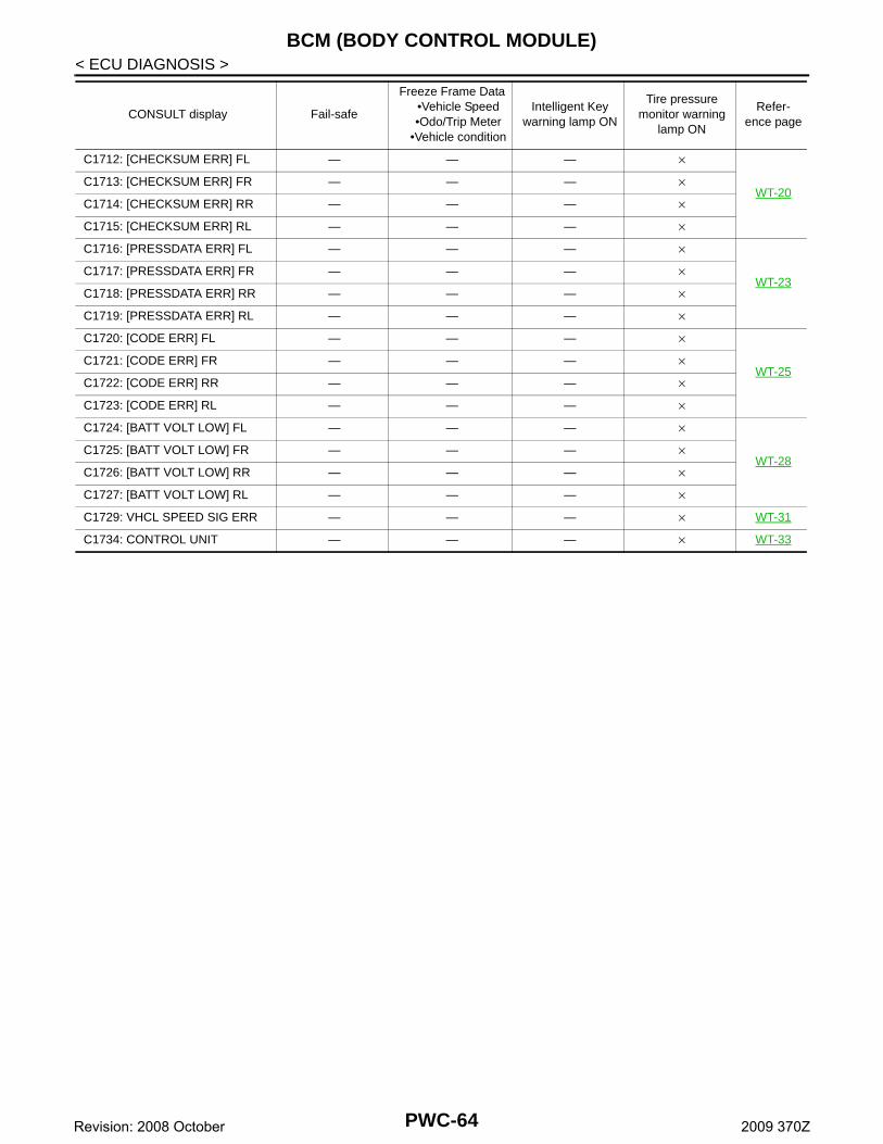
BCM (BODY CONTROL MODULE)
< ECU DIAGNOSIS >C1712: [CHECKSUM ERR] FL — — — ×
WT-20C1713: [CHECKSUM ERR] FR — — — ×
C1714: [CHECKSUM ERR] RR — — — ×
C1715: [CHECKSUM ERR] RL — — — ×
C1716: [PRESSDATA ERR] FL — — — ×
WT-23C1717: [PRESSDATA ERR] FR — — — ×
C1718: [PRESSDATA ERR] RR — — — ×
C1719: [PRESSDATA ERR] RL — — — ×
C1720: [CODE ERR] FL — — — ×
WT-25C1721: [CODE ERR] FR — — — ×
C1722: [CODE ERR] RR — — — ×
C1723: [CODE ERR] RL — — — ×
C1724: [BATT VOLT LOW] FL — — — ×
WT-28C1725: [BATT VOLT LOW] FR — — — ×
C1726: [BATT VOLT LOW] RR — — — ×
C1727: [BATT VOLT LOW] RL — — — ×
C1729: VHCL SPEED SIG ERR — — — × WT-31
C1734: CONTROL UNIT — — — × WT-33
CONSULT display Fail-safe
Freeze Frame Data•Vehicle Speed•Odo/Trip Meter
•Vehicle condition
Intelligent Key warning lamp ON
Tire pressure monitor warning
lamp ON
Refer-ence page
PWC-64Revision: 2008 October 2009 370Z

POWER WINDOW MAIN SWITCH
C
D
E
F
G
H
I
J
L
M
A
B
WC
N
O
P
< ECU DIAGNOSIS >
P
POWER WINDOW MAIN SWITCH
Reference Value INFOID:0000000004461030
TERMINAL LAYOUT
PHYSICAL VALUES
POWER WINDOW MAIN SWITCH
JMKIA1191ZZ
Terminal No.(Wire color)
Description
ConditionVoltage [V](Approx.)
+ - Signal name Input/Output
1(W)
Ground Battery power supply Input — Battery voltage
5(O)
Ground Encoder power supply OutputWhen ignition switch ON or automatic window ad-justing operates
Battery voltage
6(GR)
GroundDoor key cylinder switch LOCK signal
InputKey position
(Neutral → Locked)5 → 0
7(V)
GroundDoor key cylinder switch UN-
LOCK signalInput
Key position(Neutral → Unlocked)
5 → 0
8(L)
GroundDriver side power window motor UP signal
OutputWhen power window main switch (Driver side) is op-erated UP
Battery voltage
9(LG)
Ground Encoder pulse signal 2 InputWhen power window mo-tor operates
10(Y)
Ground Ignition switch power signal InputIGN SW ON Battery voltage
IGN SW OFF 0
11(BR)
GroundDriver side power window motor DOWN signal
OutputWhen power window main switch (Driver side) is op-erated DOWN
Battery voltage
12(SB)
Ground Power window serial linkInput/Output
Ignition switch ON
JMKIA0070GB
JPMIA0013GB
PWC-65Revision: 2008 October 2009 370Z
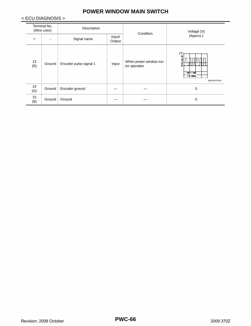
POWER WINDOW MAIN SWITCH
< ECU DIAGNOSIS >13(R)
Ground Encoder pulse signal 1 InputWhen power window mo-tor operates
14(G)
Ground Encoder ground — — 0
15(B)
Ground Ground — — 0
Terminal No.(Wire color)
Description
ConditionVoltage [V](Approx.)
+ - Signal name Input/Output
JMKIA0070GB
PWC-66Revision: 2008 October 2009 370Z

POWER WINDOW MAIN SWITCH
C
D
E
F
G
H
I
J
L
M
A
B
WC
N
O
P
< ECU DIAGNOSIS >
P
Wiring Diagram - POWER WINDOW CONTROL SYSTEM - INFOID:0000000004461031
JCKWA2035GB
PWC-67Revision: 2008 October 2009 370Z

POWER WINDOW MAIN SWITCH
< ECU DIAGNOSIS >JCKWA2036GB
PWC-68Revision: 2008 October 2009 370Z

POWER WINDOW MAIN SWITCH
C
D
E
F
G
H
I
J
L
M
A
B
WC
N
O
P
< ECU DIAGNOSIS >
P
JCKWA2037GB
PWC-69Revision: 2008 October 2009 370Z

POWER WINDOW MAIN SWITCH
< ECU DIAGNOSIS >Fail-Safe INFOID:0000000004461032
FAIL-SAFE CONTROLSwitches to fail-safe control when malfunction is detected in encoder signal that detects up/down speed anddirection of door glass. Switches to fail-safe control when a signal that is out of the specified value is detectedbetween the fully closed position and the actual position of the glass.
JCKWA2038GB
PWC-70Revision: 2008 October 2009 370Z

POWER WINDOW MAIN SWITCH
C
D
E
F
G
H
I
J
L
M
A
B
WC
N
O
P
< ECU DIAGNOSIS >
P
In fail-safe control, the system changes to a non-initialized condition and the following functions do not oper-ate.• AUTO UP operation• Anti-pinch function• Automatic window adjusting function
When fail-safe control is activated, perform initializing operation to recover. If a malfunction is detected inpower window switch, fail-safe control is activated again.
Malfunction Malfunction condition
Pulse sensor malfunctionWhen one pulse signals that is the specified value or more is detected continuously for the specified time or more, while door glass is being operated UP or DOWN.
Both pulse sensor mal-function
When both pulse signal are not detected continuously for the specified time or more, while door glass is being operated UP or DOWN.
Pulse direction malfunc-tion
When a pulse indicating that the window is moving in the opposite direction against the power win-dow motor is detected for the specified value or more, while door glass is being operated UP or DOWN.
Glass recognition position malfunction 1
When the actual door glass position that is out of the specified value is detected compared to the door glass fully closed position memorized in module, while door is being operated UP or DOWN.
Glass recognition position malfunction 2
When pulse count that is out of door glass full stroke value or more is detected, while door glass is being operated UP or DOWN.
PWC-71Revision: 2008 October 2009 370Z

POWER WINDOW SUB-SWITCH
< ECU DIAGNOSIS >POWER WINDOW SUB-SWITCH
Reference Value INFOID:0000000004461033
TERMINAL LAYOUT
PHYSICAL VALUES
JMKIA0134ZZ
Terminal No.(Wire color)
Description
ConditionVoltage [V](Approx.)
+ - Signal nameInput/Output
3(G)
Ground Encoder ground — — 0
4(O)
Ground Encoder power supply OutputWhen ignition switch ON or automatic window operates adjusting
Battery voltage
8(L)
GroundPower window motorUP signal
OutputWhen power window motor isoperated UP
Battery voltage
9(BR)
GroundPower window motor DOWN signal
OutputWhen power window motor isoperated DOWN
Battery voltage
10(W)
Ground Battery power supply Input — Battery voltage
11(B)
Ground Ground — — 0
12(R)
Ground Encoder pulse signal 1 InputWhen power window motor operates
JMKIA0070GB
PWC-72Revision: 2008 October 2009 370Z

POWER WINDOW SUB-SWITCH
C
D
E
F
G
H
I
J
L
M
A
B
WC
N
O
P
< ECU DIAGNOSIS >
P
15(LG)
Ground Encoder pulse signal 2 InputWhen power window motor operates
16(Y)
Ground Power window serial linkInput/Output
Ignition switch ON
Terminal No.(Wire color)
Description
ConditionVoltage [V](Approx.)
+ - Signal nameInput/Output
JMKIA0070GB
JPMIA0013GB
PWC-73Revision: 2008 October 2009 370Z

POWER WINDOW SUB-SWITCH
< ECU DIAGNOSIS >Wiring Diagram - POWER WINDOW CONTROL SYSTEM - INFOID:0000000004461034
JCKWA2035GB
PWC-74Revision: 2008 October 2009 370Z

POWER WINDOW SUB-SWITCH
C
D
E
F
G
H
I
J
L
M
A
B
WC
N
O
P
< ECU DIAGNOSIS >
P
JCKWA2036GB
PWC-75Revision: 2008 October 2009 370Z

POWER WINDOW SUB-SWITCH
< ECU DIAGNOSIS >JCKWA2037GB
PWC-76Revision: 2008 October 2009 370Z

POWER WINDOW SUB-SWITCH
C
D
E
F
G
H
I
J
L
M
A
B
WC
N
O
P
< ECU DIAGNOSIS >
P
Fail-Safe INFOID:0000000004461035
FAIL-SAFE CONTROLSwitches to fail-safe control when malfunction is detected in encoder signal that detects up/down speed anddirection of door glass. Switches to fail-safe control when a signal that is out of the specified value is detectedbetween the fully closed position and the actual position of the glass.
JCKWA2038GB
PWC-77Revision: 2008 October 2009 370Z
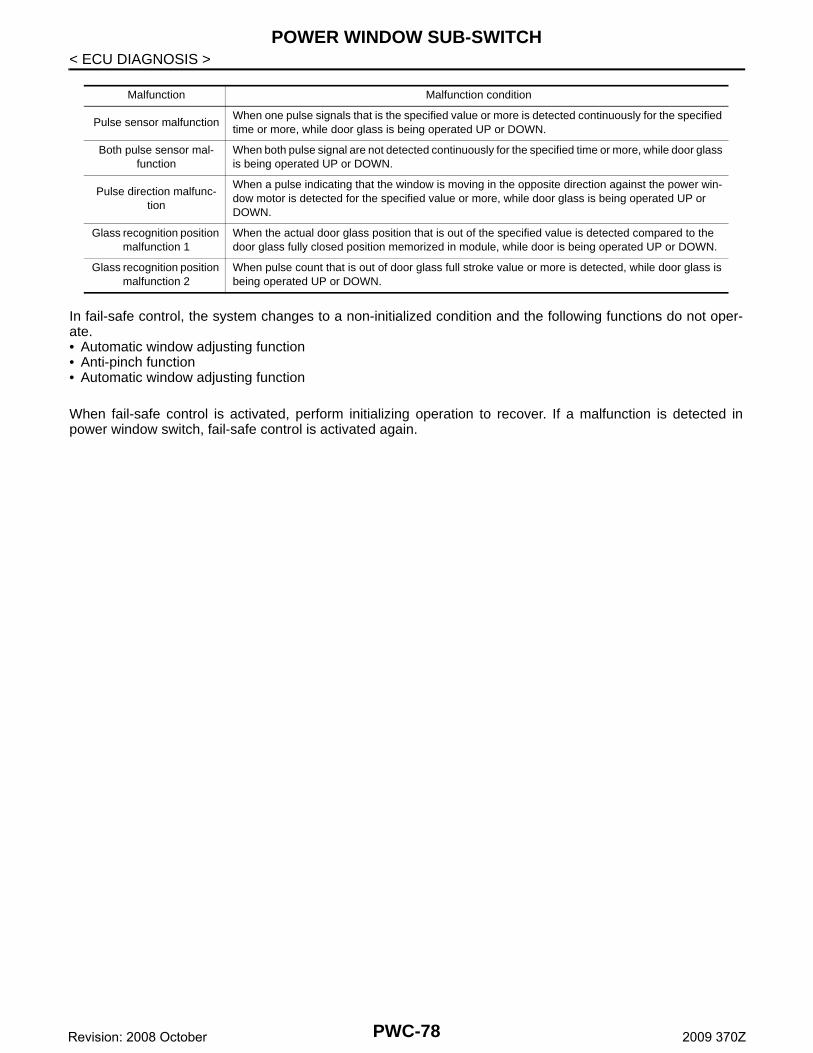
POWER WINDOW SUB-SWITCH
< ECU DIAGNOSIS >In fail-safe control, the system changes to a non-initialized condition and the following functions do not oper-ate.• Automatic window adjusting function• Anti-pinch function• Automatic window adjusting function
When fail-safe control is activated, perform initializing operation to recover. If a malfunction is detected inpower window switch, fail-safe control is activated again.
Malfunction Malfunction condition
Pulse sensor malfunctionWhen one pulse signals that is the specified value or more is detected continuously for the specified time or more, while door glass is being operated UP or DOWN.
Both pulse sensor mal-function
When both pulse signal are not detected continuously for the specified time or more, while door glass is being operated UP or DOWN.
Pulse direction malfunc-tion
When a pulse indicating that the window is moving in the opposite direction against the power win-dow motor is detected for the specified value or more, while door glass is being operated UP or DOWN.
Glass recognition position malfunction 1
When the actual door glass position that is out of the specified value is detected compared to the door glass fully closed position memorized in module, while door is being operated UP or DOWN.
Glass recognition position malfunction 2
When pulse count that is out of door glass full stroke value or more is detected, while door glass is being operated UP or DOWN.
PWC-78Revision: 2008 October 2009 370Z

POWER WINDOWS DO NOT OPERATE WITH ANY POWER WINDOW SWITCH-ES
C
D
E
F
G
H
I
J
L
M
A
B
WC
N
O
P
< SYMPTOM DIAGNOSIS >
P
SYMPTOM DIAGNOSISPOWER WINDOWS DO NOT OPERATE WITH ANY POWER WINDOWSWITCHES
Description INFOID:0000000004471838
All power windows do not operate via power window main switch and power window sub-switch.
Diagnosis Procedure INFOID:0000000004461036
1.CHECK BCM POWER SUPPLY AND GROUND CIRCUIT
Check BCM power supply and ground circuit.Refer to PWC-14, "BCM : Diagnosis Procedure".Is the inspection result normal?YES >> GO TO 2.NO >> Repair or replace the malfunctioning parts.
2.CONFIRM THE OPERATION
Confirm the operation again.Is the result normal?YES >> Check intermittent incident. Refer to GI-39, "Intermittent Incident".NO >> GO TO 1.
PWC-79Revision: 2008 October 2009 370Z

DRIVER SIDE POWER WINDOW ALONE DOES NOT OPERATE
< SYMPTOM DIAGNOSIS >DRIVER SIDE POWER WINDOW ALONE DOES NOT OPERATE
Description INFOID:0000000004471840
Driver side power window does not operate using power window main switch.
Diagnosis Procedure INFOID:0000000004461037
1.CHECK POWER WINDOW MAIN SWITCH POWER SUPPLY AND GROUND CIRCUIT
Check power window main switch power supply and ground circuit.Refer to PWC-14, "POWER WINDOW MAIN SWITCH : Diagnosis Procedure".Is the inspection result normal?YES >> GO TO 2.NO >> Repair or replace the malfunctioning parts.
2.CHECK DRIVER SIDE POWER WINDOW MOTOR
Check driver side power window motor. Refer to PWC-17, "DRIVER SIDE : Component Function Check".Is the measurement value within the specification?YES >> GO TO 3.NO >> Repair or replace the malfunctioning parts.
3.CONFIRM THE OPERATION
Confirm the operation again.Is the result normal?YES >> Check intermittent incident. Refer to GI-39, "Intermittent Incident".NO >> GO TO 1.
PWC-80Revision: 2008 October 2009 370Z
PASSENGER SIDE POWER WINDOW ALONE DOES NOT OPERATE
C
D
E
F
G
H
I
J
L
M
A
B
WC
N
O
P
< SYMPTOM DIAGNOSIS >
P
PASSENGER SIDE POWER WINDOW ALONE DOES NOT OPERATEWHEN POWER WINDOW MAIN SWITCH IS OPERATED
WHEN POWER WINDOW MAIN SWITCH IS OPERATED : Description INFOID:0000000004471847
Passenger side power window operates using power window sub-switch but does not operate using powerwindow main switch.
WHEN POWER WINDOW MAIN SWITCH IS OPERATED : Diagnosis ProcedureINFOID:0000000004461038
1.CHECK POWER WINDOW SUB-SWITCH POWER SUPPLY AND GROUND CIRCUIT
Check power window sub-switch power supply and ground circuit. Refer to PWC-15, "POWER WINDOW SUB-SWITCH : Diagnosis Procedure".Is the inspection result normal?YES >> GO TO 2.NO >> Repair or replace the malfunctioning parts.
2.CHECK POWER WINDOW SUB-SWITCH SERIAL LINK CIRCUIT
Check power window sub-switch serial link circuit. Refer to PWC-27, "POWER WINDOW SUB-SWITCH : Component Function Check".Is the inspection result normal?YES >> GO TO 3.NO >> Repair or replace the malfunctioning parts.
3.CONFIRM THE OPERATION
Confirm the operation again.Is the result normal?YES >> Check intermittent incident. Refer to GI-39, "Intermittent Incident".NO >> GO TO 1.
WHEN POWER WINDOW SUB-SWITCH IS OPERATED
WHEN POWER WINDOW SUB-SWITCH IS OPERATED : Description INFOID:0000000004471846
Passenger side power window operates using power window main switch but not using power window sub-switch.
WHEN POWER WINDOW SUB-SWITCH IS OPERATED : Diagnosis ProcedureINFOID:0000000004471849
1.CHECK POWER WINDOW SUB-SWITCH POWER SUPPLY AND GROUND CIRCUIT
Check power window sub-switch power supply and ground circuit. Refer to PWC-15, "POWER WINDOW SUB-SWITCH : Diagnosis Procedure".Is the inspection result normal?YES >> GO TO 2.NO >> Repair or replace the malfunctioning parts.
2.CONFIRM THE OPERATION
Confirm the operation again.Is the result normal?YES >> Check intermittent incident. Refer to GI-39, "Intermittent Incident".NO >> GO TO 1.
WITH BOTH POWER WINDOW MAIN SWITCH AND POWER WINDOW SUB-SWITCH
WITH BOTH POWER WINDOW MAIN SWITCH AND POWER WINDOW SUB-
PWC-81Revision: 2008 October 2009 370Z

PASSENGER SIDE POWER WINDOW ALONE DOES NOT OPERATE
< SYMPTOM DIAGNOSIS >SWITCH : Description INFOID:0000000004471848
Passenger side power window operates using power window main switch and power window sub-switch.
WITH BOTH POWER WINDOW MAIN SWITCH AND POWER WINDOW SUB-SWITCH : Diagnosis Procedure INFOID:0000000004471850
1.CHECK PASSENGER SIDE POWER WINDOW MOTOR
Check passenger side power window motor. Refer to PWC-18, "PASSENGER SIDE : Component Function Check".Is the measurement value within the specification?YES >> GO TO 2.NO >> Repair or replace the malfunctioning parts.
2.CONFIRM THE OPERATION
Confirm the operation again.Is the result normal?YES >> Check intermittent incident. Refer to GI-39, "Intermittent Incident".NO >> GO TO 1.
PWC-82Revision: 2008 October 2009 370Z

ANTI-PINCH FUNCTION DOES NOT OPERATE
C
D
E
F
G
H
I
J
L
M
A
B
WC
N
O
P
< SYMPTOM DIAGNOSIS >
P
ANTI-PINCH FUNCTION DOES NOT OPERATEDRIVER SIDE
DRIVER SIDE : Description INFOID:0000000004471851
Anti-pinch function does not operate when power window up operated.
DRIVER SIDE : Diagnosis Procedure INFOID:0000000004461039
1.CHECK AUTO UP OPERATION
Check AUTO UP operation.Is the inspection result normal?YES >> GO TO 2.NO >> Refer to PWC-84, "DRIVER SIDE : Diagnosis Procedure".
2.CONFIRM THE OPERATION
Confirm the operation again.Is the result normal?YES >> Check intermittent incident. Refer to GI-39, "Intermittent Incident".NO >> GO TO 1.
PASSENGER SIDE
PASSENGER SIDE : Description INFOID:0000000004471852
Anit-pinch function does not operate when power window up operated.
PASSENGER SIDE : Diagnosis Procedure INFOID:0000000004471854
1.CHECK AUTO UP OPERATION
Check AUTO UP operation.Is the inspection result normal?YES >> GO TO 2.NO >> Refer to PWC-84, "PASSENGER SIDE : Diagnosis Procedure".
2.CONFIRM THE OPERATION
Confirm the operation again.Is the result normal?YES >> Check intermittent incident. Refer to GI-39, "Intermittent Incident".NO >> GO TO 1.
PWC-83Revision: 2008 October 2009 370Z
AUTO OPERATION DOES NOT OPERATE BUT MANUAL OPERATES NORMAL-LY
< SYMPTOM DIAGNOSIS >
AUTO OPERATION DOES NOT OPERATE BUT MANUAL OPERATESNORMALLYDRIVER SIDE
DRIVER SIDE : Diagnosis Procedure INFOID:0000000004461040
1.PERFORM INITIALIZATION PROCEDURE
Initialization procedure is performed and operation is confirmed.Refer to PWC-5, "ADDITIONAL SERVICE WHEN REMOVING BATTERY NEGATIVE TERMINAL : SpecialRepair Requirement".Is the inspection result normal?YES >> INSPECTION ENDNO >> GO TO 2.
2.CHECK ENCODER (DRIVER SIDE) CIRCUIT
Check encoder (driver side) circuit. Refer to PWC-21, "DRIVER SIDE : Component Function Check".Is the inspection result normal?YES >> GO TO 3.NO >> Repair or replace the malfunctioning parts.
3.CONFIRM THE OPERATION
Confirm the operation again.Is the result normal?YES >> Check intermittent incident. Refer to GI-39, "Intermittent Incident".NO >> GO TO 1.
PASSENGER SIDE
PASSENGER SIDE : Diagnosis Procedure INFOID:0000000004461041
1.PERFORM INITIALIZATION PROCEDURE
Initialization procedure is performed and operation is confirmed.Refer to PWC-5, "ADDITIONAL SERVICE WHEN REMOVING BATTERY NEGATIVE TERMINAL : SpecialRepair Requirement".Is the inspection result normal?YES >> INSPECTION ENDNO >> GO TO 2.
2.CHECK ENCODER (PASSENGER SIDE) CIRCUIT
Check encoder (passenger side) circuit. Refer to PWC-23, "PASSENGER SIDE : Component Function Check".Is the inspection result normal?YES >> GO TO 3.NO >> Repair or replace the malfunctioning parts.
3.CONFIRM THE OPERATION
Confirm the operation again.Is the result normal?YES >> Check intermittent incident. Refer to GI-39, "Intermittent Incident".NO >> GO TO 1.
PWC-84Revision: 2008 October 2009 370Z
POWER WINDOW RETAINED POWER FUNCTION DOES NOT OPERATE NOR-MALLY
C
D
E
F
G
H
I
J
L
M
A
B
WC
N
O
P
< SYMPTOM DIAGNOSIS >
P
POWER WINDOW RETAINED POWER FUNCTION DOES NOT OPERATENORMALLY
Description INFOID:0000000004478548
Retained power function does not operate after ignition switch turns OFF.
Diagnosis Procedure INFOID:0000000004476280
1.CHECK DOOR SWITCH
Check door switch. Refer to DLK-60, "Component Function Check".Is the inspection result normal?YES >> GO TO 2.NO >> Repair or replace the malfunctioning parts.
2.CONFIRM THE OPERATION
Confirm the operation again.Is the result normal?YES >> Check intermittent incident. Refer to GI-39, "Intermittent Incident".NO >> GO TO 1.
PWC-85Revision: 2008 October 2009 370Z

DOOR KEY CYLINDER SWITCH DOES NOT OPERATE POWER WINDOWS
< SYMPTOM DIAGNOSIS >DOOR KEY CYLINDER SWITCH DOES NOT OPERATE POWER WIN-DOWS
Description INFOID:0000000004478549
Power window does not operate when locking or unlocking a door using door key cylinder.
Diagnosis Procedure INFOID:0000000004476281
1.PERFORM INITIALIZATION PROCEDURE
Initialization procedure is executed and operation is confirmed.Refer to PWC-5, "ADDITIONAL SERVICE WHEN REMOVING BATTERY NEGATIVE TERMINAL : SpecialRepair Requirement".Is the inspection result normal?YES >> INSPECTION ENDNO >> GO TO 2.
2.CHECK DRIVER SIDE DOOR LOCK ASSEMBLY (DOOR KEY CYLINDER SWITCH)
Check driver side door lock assembly (door key cylinder switch).Refer to DLK-70, "Component Function Check".Is the inspection result normal?YES >> GO TO 3.NO >> Repair or replace the malfunctioning parts.
3.CONFIRM THE OPERATION
Confirm the operation again.Is the result normal?YES >> Check intermittent incident. Refer to GI-39, "Intermittent Incident".NO >> GO TO 1.
PWC-86Revision: 2008 October 2009 370Z
KEYLESS POWER WINDOW DOWN DOES NOT OPERATE
C
D
E
F
G
H
I
J
L
M
A
B
WC
N
O
P
< SYMPTOM DIAGNOSIS >
P
KEYLESS POWER WINDOW DOWN DOES NOT OPERATE
Description INFOID:0000000004478550
Power window down does not operate when pressing unlock button on Intelligent Key.
Diagnosis Procedure INFOID:0000000004476282
1.CHECK REMOTE KEYLESS ENTRY FUNCTION
Check remote keyless entry function.Does door lock/unlock with Intelligent Key button?YES >> GO TO 2.NO >> Refer to DLK-164, "Description".
2.CHECK POWER WINDOW OPERATION
Check power window operation.Does power window operate up/down using power window main switch?YES >> GO TO 3.NO >> Refer to DLK-164, "Diagnosis Procedure".
3.CHECK “PW DOWN SET” SETTING IN “WORK SUPPORT”
Check “PW DOWN SET” setting in “WORK SUPPORT”.Refer to DLK-49, "INTELLIGENT KEY : CONSULT-III Function (BCM - INTELLIGENT KEY)".Is the inspection result normal?YES >> GO TO 4.NO >> Set “PW DOWN SET” setting in “WORK SUPPORT”.
4.CONFIRM THE OPERATION
Confirm the operation again.Is the result normal?YES >> Check intermittent incident. Refer to GI-39, "Intermittent Incident".NO >> GO TO 1.
PWC-87Revision: 2008 October 2009 370Z

POWER WINDOW LOCK SWITCH DOES NOT FUNCTION
< SYMPTOM DIAGNOSIS >POWER WINDOW LOCK SWITCH DOES NOT FUNCTION
Diagnosis Procedure INFOID:0000000004461042
1.REPLACE POWER WINDOW MAIN SWITCH
Replace power window main switch.
>> Refer to PWC-93, "Removal and Installation".
PWC-88Revision: 2008 October 2009 370Z
POWER WINDOW SWITCH ILLUMINATION DOES NOT ILLUMINATE
C
D
E
F
G
H
I
J
L
M
A
B
WC
N
O
P
< SYMPTOM DIAGNOSIS >
P
POWER WINDOW SWITCH ILLUMINATION DOES NOT ILLUMINATEDRIVER SIDE
DRIVER SIDE : Diagnosis Procedure INFOID:0000000004461043
1.REPLACE POWER WINDOW MAIN SWITCH
Replace power window main switch.
>> Refer to PWC-93, "Removal and Installation".PASSENGER SIDE
PASSENGER SIDE : Diagnosis Procedure INFOID:0000000004461044
1.REPLACE POWER WINDOW SUB-SWITCH
Replace power window sub-switch.
>> Refer to PWC-93, "Removal and Installation".
PWC-89Revision: 2008 October 2009 370Z

AUTOMATIC WINDOW ADJUSTING FUNCTION DOES NOT OPERATE
< SYMPTOM DIAGNOSIS >AUTOMATIC WINDOW ADJUSTING FUNCTION DOES NOT OPERATEDRIVER SIDE
DRIVER SIDE : Diagnosis Procedure INFOID:0000000004461045
1.CHECK AUTO UP OPERATION
Check AUTO UP operation.Is the inspection result normal?YES >> GO TO 2.NO >> Refer to PWC-84, "DRIVER SIDE : Diagnosis Procedure".
2.CHECK DOOR SWITCH
Check door switch.Refer to DLK-60, "Component Function Check".Is the inspection result normal?YES >> GO TO 3.NO >> Repair or replace the malfunctioning parts.
3.CHECK POWER WINDOW SERIAL LINK (POWER WINDOW MAIN SWITCH)
Check power window serial link (power window main switch)Refer to PWC-26, "POWER WINDOW MAIN SWITCH : Component Function Check"Is the result normal?YES >> GO TO 4.NO >> Repair or replace the malfunctioning parts
4.CONFIRM THE OPERATION
Confirm the operation again.Is the result normal?YES >> Check intermittent incident. Refer to GI-39, "Intermittent Incident".NO >> GO TO 1.
PASSENGER SIDE
PASSENGER SIDE : Diagnosis Procedure INFOID:0000000004461046
1.PERFORM INITIALIZATION PROCEDURE
Initialization procedure is performed and operation is confirmed.Refer to PWC-5, "ADDITIONAL SERVICE WHEN REMOVING BATTERY NEGATIVE TERMINAL : SpecialRepair Requirement".Is the inspection result normal?YES >> INSPECTION ENDNO >> GO TO 2.
2.CHECK DOOR SWITCH
Check door switch.Refer to DLK-60, "Component Function Check".Is the inspection result normal?YES >> GO TO 3.NO >> Repair or replace the malfunctioning parts.
3.CHECK POWER WINDOW SERIAL LINK (POWER WINDOW SUB-SWITCH)
Check power window serial link (power window sub-switch)Refer to PWC-27, "POWER WINDOW SUB-SWITCH : Component Function Check"Is the result normal?YES >> GO TO 4.NO >> Repair or replace the malfunctioning parts
PWC-90Revision: 2008 October 2009 370Z

AUTOMATIC WINDOW ADJUSTING FUNCTION DOES NOT OPERATE
C
D
E
F
G
H
I
J
L
M
A
B
WC
N
O
P
< SYMPTOM DIAGNOSIS >
P
4.CONFIRM THE OPERATION
Confirm the operation again.Is the result normal?YES >> Check intermittent incident. Refer to GI-39, "Intermittent Incident".NO >> GO TO 1.
PWC-91Revision: 2008 October 2009 370Z
PRECAUTIONS
< PRECAUTION >PRECAUTIONPRECAUTIONS
Precaution for Supplemental Restraint System (SRS) "AIR BAG" and "SEAT BELT PRE-TENSIONER" INFOID:0000000004461047
The Supplemental Restraint System such as “AIR BAG” and “SEAT BELT PRE-TENSIONER”, used alongwith a front seat belt, helps to reduce the risk or severity of injury to the driver and front passenger for certaintypes of collision. This system includes seat belt switch inputs and dual stage front air bag modules. The SRSsystem uses the seat belt switches to determine the front air bag deployment, and may only deploy one frontair bag, depending on the severity of a collision and whether the front occupants are belted or unbelted.Information necessary to service the system safely is included in the “SRS AIRBAG” and “SEAT BELT” of thisService Manual.WARNING:• To avoid rendering the SRS inoperative, which could increase the risk of personal injury or death in
the event of a collision which would result in air bag inflation, all maintenance must be performed byan authorized NISSAN/INFINITI dealer.
• Improper maintenance, including incorrect removal and installation of the SRS, can lead to personalinjury caused by unintentional activation of the system. For removal of Spiral Cable and Air BagModule, see the “SRS AIRBAG”.
• Never use electrical test equipment on any circuit related to the SRS unless instructed to in this Ser-vice Manual. SRS wiring harnesses can be identified by yellow and/or orange harnesses or harnessconnectors.
PRECAUTIONS WHEN USING POWER TOOLS (AIR OR ELECTRIC) AND HAMMERSWhen working near the Airbag Diagnosis Sensor Unit or other Airbag System sensors while ignition switch isON or engine is running, never use air or electric power tools or strike near the sensor(s) with a hammer.Heavy vibration may activate the sensor(s), deploy the airbag(s), possibly cause serious injury.When using air or electric power tools or hammers, always turn OFF ignition switch, disconnect the battery,and wait 3 minutes or more before performing any service.
Precaution for Battery Service INFOID:0000000004757265
Before disconnecting the battery, lower both the driver and passenger windows. This will prevent any interfer-ence between the window edge and the vehicle when the door is opened/closed. During normal operation, thewindow slightly raises and lowers automatically to prevent any window to vehicle interference. The automaticwindow function will not work with the battery disconnected.
PWC-92Revision: 2008 October 2009 370Z

POWER WINDOW MAIN SWITCH
C
D
E
F
G
H
I
J
L
M
A
B
WC
N
O
P
< ON-VEHICLE REPAIR >
P
ON-VEHICLE REPAIRPOWER WINDOW MAIN SWITCH
Removal and Installation INFOID:0000000004461050
REMOVAL1. Remove the power window main switch finisher (2).
Refer to INT-11, "Removal and Installation".2. Power window main switch (1) is removed from power window
main switch finisher (2) using flat-bladed screw driver (A) etc.
CAUTION:Never fold the pawl of power window main switch finisher.NOTE:The same procedure is also performed for power window sub-switch.
INSTALLATIONInstall in the reverse order of removal.NOTE:Power window main switch is replaced or is removed it is necessary to do the initialization procedure.Refer to PWC-6, "ADDITIONAL SERVICE WHEN REPLACING CONTROL UNIT : Special Repair Require-ment".
: Pawl
JMKIA3419ZZ
PWC-93Revision: 2008 October 2009 370Z

![Calendario Fiscal PwC Costa Rica · conformada por siete firmas: PwC Panamá, PwC Costa Rica, PwC El Salvador, PwC Nicaragua, ... Ralph Waldo Emerson [Escritor y Poeta] 15; Mensuales-03:](https://img.pdfslide.net/doc/110x75/5bb099af09d3f2830e8c5016/calendario-fiscal-pwc-costa-rica-conformada-por-siete-firmas-pwc-panama-pwc.jpg)