Embed Size (px)
Citation preview
UNISONIC Technologies Co., Ltd.
PWM IC For SMPS IntroductionOB2263 OB2273
UTC Semiconductor Professional Design
Rev. 1.0
May 2013
Support. Service. Solution.
Http://www.unisonic.com.tw
UTC Semiconductor
Professional Design
Support. Service. Solution.
Content
‧ Cover Page - - - - - - - - - - - - - - - - - - - - - - - - - - - - - - - - - - - - - - - - - - - - - -
‧ Contents - - - - - - - - - - - - - - - - - - - - - - - - - - - - - - - - - - - - - - - - - - - - - - - -
‧ UTC Semiconductor Provides - - - - - - - - - - - - - - - - - - - - - - - - - - - - - - - -
‧ UTC SMPS Product Line - - - - - - - - - - - - - - - - - - - - - - - - - - - - - - - - - - - -
‧ UTC SMPS Applications - - - - - - - - - - - - - - - - - - - - - - - - - - - - - - - - - - - -
‧ UTC Power Consumption- - - - - - - - - - - - - - - - - - - - - - - - - - - - - - - - - - - -
‧ Total of Power Supply Functions - - - - - - - - - - - - - - - - - - - - - - - - - - - - - -
‧ AC To DC Switching Portfolio - - - - - - - - - - - - - - - - - - - - - - - - - - - - - - - - -
‧ A/D Voltage Mode PWM IC Design Reference - - - - - - - - - - - - - - - - - - - - -
‧ A/D Voltage Mode PWM IC Controller Introduce - - - - - - - - - - - - - - - - - - - - - - - - - - - -
‧ A/D Current Mode PWM IC Design Reference - - - - - - - - - - - - - - - - - - - - -
‧ A/D Current Mode PWM IC Controller Introduce - - - - - - - - - - - - - - - - - - - - - - - - - - - -
‧ A/D Green Mode PWM IC Design Reference - - - - - - - - - - - - - - - - - - - - -
‧ A/D Green Mode PWM IC Controller Introduce - - - - - - - - - - - - - - - - - - - - - - - - - - - -
‧ Green Mode UC3863 10W 5V/2A Demo Board Performance - - - - - - - - - - - - - - - - - -
‧ A/D PWM Power Switcher Design Reference - - - - - - - - - - - - - - - - - - - - -
‧ A/D Green Mode PWM IC Controller Introduce - - - - - - - - - - - - - - - - - - - - - - - - - - - - -
‧ Power Switcher Green Mode UPS603 12W 12V/1A Demo Board Performance - - - - - -
‧ Power Factor Controller Design Reference - - - - - - - - - - - - - - - - - - - - - - -
‧ PFC Controller Introduce - - - - - - - - - - - - - - - - - - - - - - - - - - - - - - - - - - - - - - - - - - - - -
‧ UA7527 20W 27V/0.75A Demo Board Performance- - - - - - - - - - - - - - - - - - - - - - - - - -
‧ Power Factor Correction and PWM IC Design Reference - - - - - - - - - - - -
‧ PFC and PWM Combo Controller Introduce - - - - - - - - - - - - - - - - - - - - - - - - - - - - - - -
‧ Sales and Design Assistance from UTC - - - - - - - - - - - - - - - - - - - - - - - - -
PWM IC For Power Total Solution
Page
1
2
3
4
5
6
7
8
9/10
10
11/14
12/14
15/22
15/19
20/22
23/30
24/27
28/30
31/36
32/34
35/36
37/38
38
39
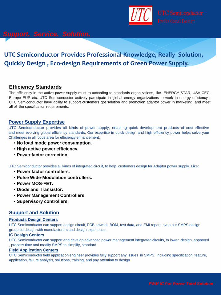
UTC Semiconductor Provides Professional Knowledge, Really Solution,
Quickly Design , Eco-design Requirements of Green Power Supply.
UTC Semiconductor
Professional Design
Support. Service. Solution.
Efficiency Standards The efficiency in the active power supply must to according to standards organizations, like ENERGY STAR, USA CEC,
Europe EUP etc. UTC Semiconductor actively participate in global energy organizations to work in energy efficiency .
UTC Semiconductor have ability to support customers got solution and promotion adaptor power in marketing, and meet
all of the specification requirements.
Power Supply Expertise UTC Semiconductor provides all kinds of power supply, enabling quick development products of cost-effective
and meet evolving global efficiency standards. Our expertise in quick design and high efficiency power helps solve your
Challenges in all focus area for efficiency enhancement:
‧No load mode power consumption.
‧High active power efficiency.
‧Power factor correction.
UTC Semiconductor provides all kinds of integrated circuit, to help customers design for Adaptor power supply. Like:
‧Power factor controllers.
‧Pulse Wide-Modulation controllers.
‧Power MOS-FET.
‧Diode and Transistor.
‧Power Management Controllers.
‧Supervisory controllers.
Support and Solution Products Design Centers UTC Semiconductor can support design circuit, PCB artwork, BOM, test data, and EMI report, even our SMPS design
group co-design with manufacturers and design experience.
IC Design Centers
UTC Semiconductor can support and develop advanced power management integrated circuits, to lower design, approved
, process time and modify SMPS to simplify, standard.
Field Application Centers
UTC Semiconductor field application engineer provides fully support any issues in SMPS. Including specification, feature,
application, failure analysis, solutions, training, and pay attention to design.
PWM IC For Power Total Solution

UTC Semiconductor
Professional Design
Support. Service. Solution.
SMPS Product Line
PWM IC For Power Total Solution
SMPS PWM
UC3863
UC3873
PFC
L8561
UA7527
MOSFET
2N60
4N60 Rectifier
MBR10100C
BYC10-600
CC.CV Controller
UM601
UM606
UTC Semiconductor
Professional Design
Support. Service. Solution.
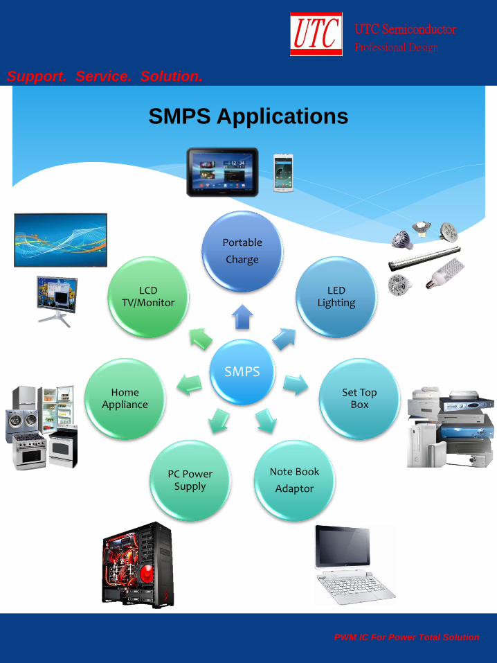
SMPS Applications
PWM IC For Power Total Solution
SMPS
Portable
Charge
LED Lighting
Set Top Box
Note Book
Adaptor
PC Power Supply
Home Appliance
LCD TV/Monitor
UTC Semiconductor
Professional Design
Support. Service. Solution.
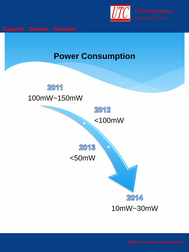
Power Consumption
PWM IC For Power Total Solution
100mW~150mW
<100mW
<50mW
10mW~30mW
UTC Semiconductor
Professional Design
Support. Service. Solution.
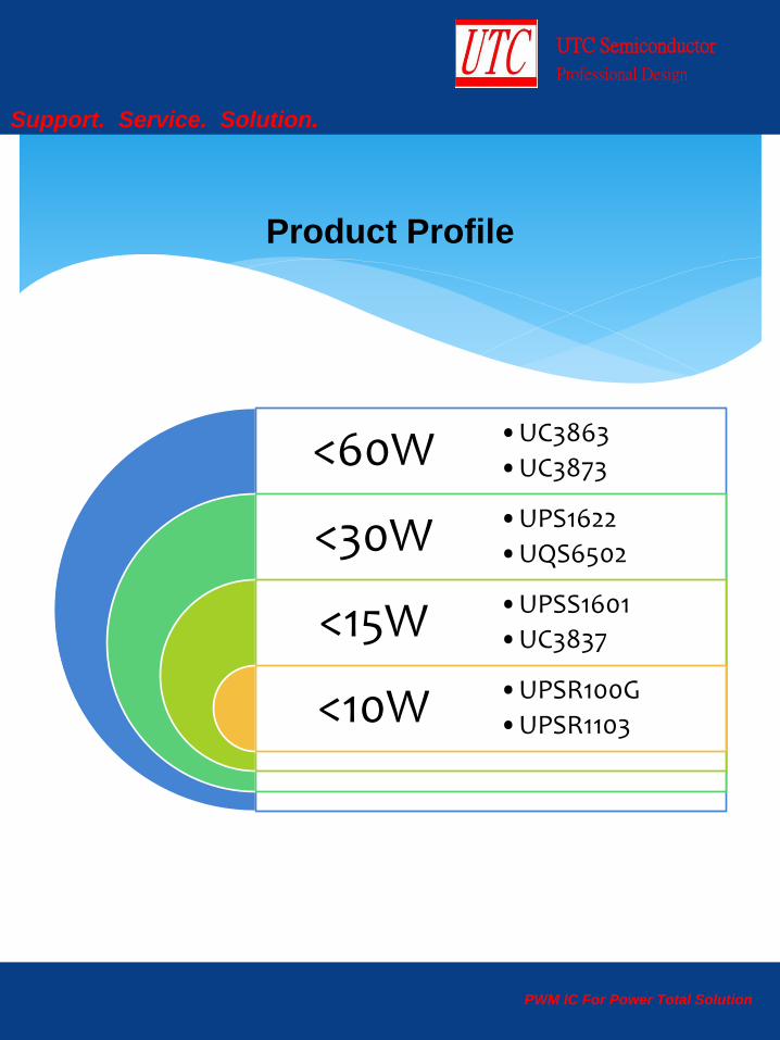
Product Profile
PWM IC For Power Total Solution
<60W
<30W
<15W
<10W
•UC3863
•UC3873
•UPS1622
•UQS6502
•UPSS1601
•UC3837
•UPSR100G
•UPSR1103
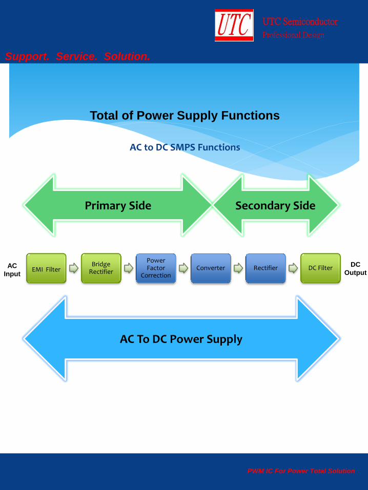
AC to DC SMPS Functions
UTC Semiconductor
Professional Design
Support. Service. Solution.
AC
Input
DC
Output
Total of Power Supply Functions
PWM IC For Power Total Solution
EMI Filter Bridge
Rectifier
Power Factor
Correction Converter Rectifier DC Filter
Primary Side Secondary Side
AC To DC Power Supply
UTC Semiconductor
Professional Design
Support. Service. Solution.
PWM IC For Power Total Solution
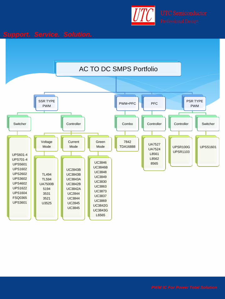
AC TO DC SMPS Portfolio
SSR TYPE
PWM
Switcher
UPS601-4
UPS701-4
UPS5601
UPS1602
UPS2602
UPS3602
UPS4602
UPS1622
UPS1604
FSQ0365
UPS3601
Controller
Voltage
Mode
TL494
TL594
UA7500B
5194
3531
3521
U3525
Current
Mode
UC2843B
UC3843B
UC3843A
UC3842B
UC3842A
UC2844
UC3844
UC2845
UC3845
Green
Mode
UC3846
UC3846B
UC3848
UC3849
UC3830
UC3863
UC3873
UC3837
UC3869
UC3842G
UC3843G
L6565
PWM+PFC
Combo
7842
TDA16888
PFC
Controller
UA7527
UA7524
L8561
L8562
8565
PSR TYPE
PWM
Controller
UPSR100G
UPSR1103
Switcher
UPSS1601
UTC Semiconductor
Professional Design
Support. Service. Solution.
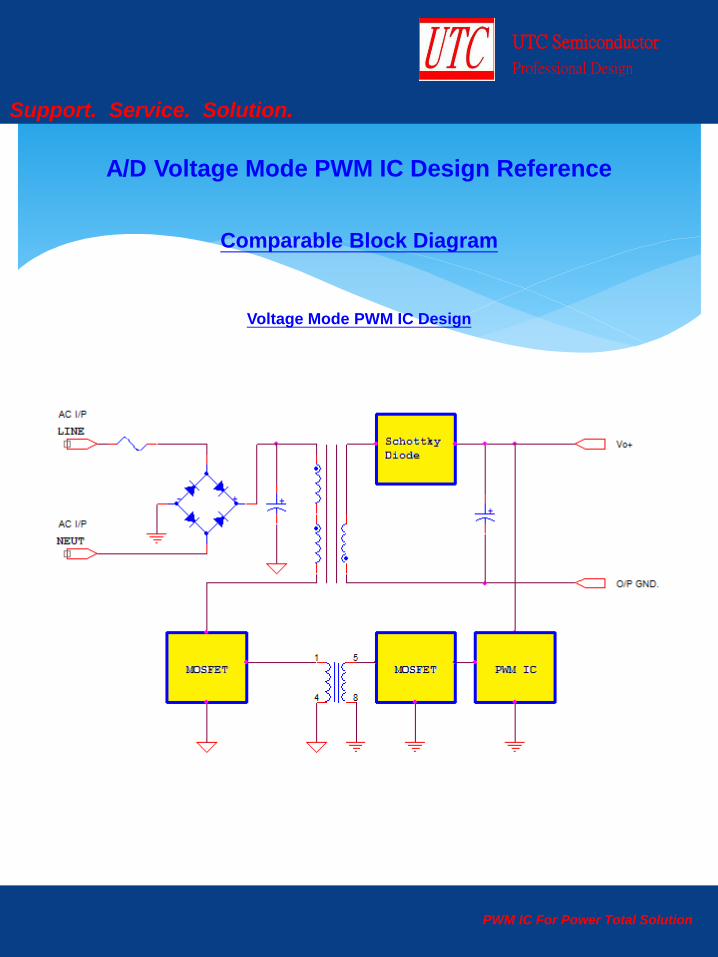
Voltage Mode PWM IC Design
A/D Voltage Mode PWM IC Design Reference
Comparable Block Diagram
PWM IC For Power Total Solution
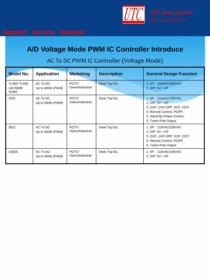
AC To DC PWM IC Controller (Voltage Mode)
Model No. Application Marketing Description General Design Function
TL494/ TL594
UA7500B/
51494
AC To DC
Up to 400W (PWM)
PC/TV
Game/Industrial
Desk Top Etc. 1. I/P: 110VAC/230VAC
2. O/P: 5V~UP
3531 AC To DC
Up to 400W (PWM)
PC/TV
Game/Industrial
Desk Top Etc.
1. I/P: 110VAC/230VAC
2. O/P: 5V~UP
3. OVP, UVP,OPP, SCP, OCP.
4. Remote Control, PG/PF.
5. Stand-By Power Control.
5. Totem Pole Output
3521 AC To DC
Up to 400W (PWM)
PC/TV
Game/Industrial
Desk Top Etc.
1. I/P: 110VAC/230VAC
2. O/P: 5V~UP
3. OVP, UVP,OPP, SCP, OCP.
4. Remote Control, PG/PF.
5. Totem Pole Output
U3525 AC To DC
Up to 400W (PWM)
PC/TV
Game/Industrial
Desk Top Etc. 1. I/P: 110VAC/230VAC
2. O/P: 5V~UP
UTC Semiconductor
Professional Design
Support. Service. Solution.
A/D Voltage Mode PWM IC Controller Introduce
UTC Semiconductor
Professional Design
Support. Service. Solution.
Current & Green Mode PWM IC Design
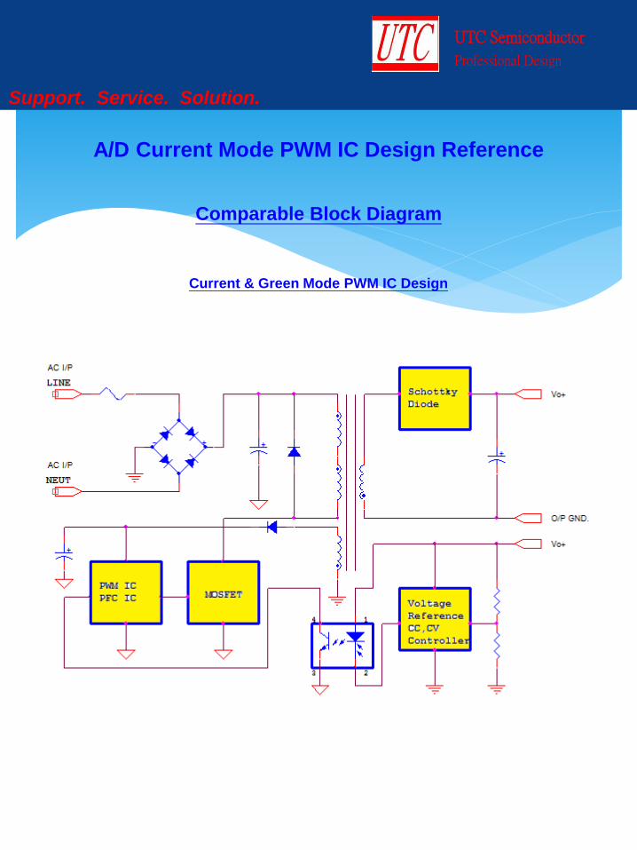
A/D Current Mode PWM IC Design Reference
Comparable Block Diagram
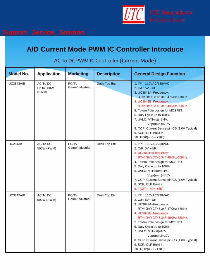
AC To DC PWM IC Controller (Current Mode)
Model No. Application Marketing Description General Design Function
UC3843A/B AC To DC
Up to 500W
(PWM)
PC/TV
Game/Industrial
Desk Top Etc. 1. I/P: 110VAC/230VAC
2. O/P: 5V~UP
3. UC3843A=Frequency:
RT=10KΩ,CT=3.3nF 47KHz-57KHz
4. UC3843B=Frequency:
RT=10KΩ,CT=3.3nF 49KHz-55KHz.
5. Totem Pole design for MOSFET.
6. Duty Cycle up to 100%.
7. UVLO: VTH(st)=8.4V.
Vopr(min.)=7.6V.
8. OCP: Current Sense pin CS (1.0V Typical)
9. SCP, OLP Build in.
10. T(OP)= -0~+70℃
UC2843B AC To DC
500W (PWM)
PC/TV
Game/Industrial
Desk Top Etc.
1. I/P: 110VAC/230VAC
2. O/P: 5V~UP
3. UC2843B=Frequency:
RT=10KΩ,CT=3.3nF 49KHz-55KHz.
4. Totem Pole design for MOSFET.
5. Duty Cycle up to 100%.
6. UVLO: VTH(st)=8.4V.
Vopr(min.)=7.6V.
7. OCP: Current Sense pin CS (1.0V Typical)
8. SCP, OLP Build in.
9. T(OP)= -40~+85℃
UC3842A/B AC To DC
500W (PWM)
PC/TV
Game/Industrial
Desk Top Etc.
1. I/P: 110VAC/230VAC
2. O/P: 5V~UP
3. UC3842A=Frequency:
RT=10KΩ,CT=3.3nF 47KHz-57KHz
4. UC3842B=Frequency:
RT=10KΩ,CT=3.3nF 49KHz-55KHz.
5. Totem Pole design for MOSFET.
6. Duty Cycle up to 100%.
7. UVLO: VTH(st)=16V.
Vopr(min.)=10V.
8. OCP: Current Sense pin CS (1.0V Typical)
9. SCP, OLP Build in.
10. T(OP)= -0~+70℃
UTC Semiconductor
Professional Design
Support. Service. Solution.
A/D Current Mode PWM IC Controller Introduce
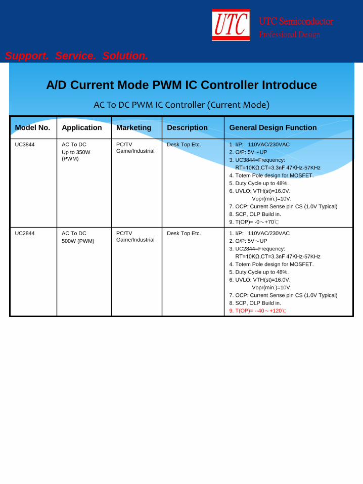
Model No. Application Marketing Description General Design Function
UC3844 AC To DC
Up to 350W
(PWM)
PC/TV
Game/Industrial
Desk Top Etc. 1. I/P: 110VAC/230VAC
2. O/P: 5V~UP
3. UC3844=Frequency:
RT=10KΩ,CT=3.3nF 47KHz-57KHz
4. Totem Pole design for MOSFET.
5. Duty Cycle up to 48%.
6. UVLO: VTH(st)=16.0V.
Vopr(min.)=10V.
7. OCP: Current Sense pin CS (1.0V Typical)
8. SCP, OLP Build in.
9. T(OP)= -0~+70℃
UC2844 AC To DC
500W (PWM)
PC/TV
Game/Industrial
Desk Top Etc. 1. I/P: 110VAC/230VAC
2. O/P: 5V~UP
3. UC2844=Frequency:
RT=10KΩ,CT=3.3nF 47KHz-57KHz
4. Totem Pole design for MOSFET.
5. Duty Cycle up to 48%.
6. UVLO: VTH(st)=16.0V.
Vopr(min.)=10V.
7. OCP: Current Sense pin CS (1.0V Typical)
8. SCP, OLP Build in.
9. T(OP)= --40~+120℃
UTC Semiconductor
Professional Design
Support. Service. Solution.
A/D Current Mode PWM IC Controller Introduce
AC To DC PWM IC Controller (Current Mode)

Model No. Application Marketing Description General Design Function
UC3845 AC To DC
350W (PWM)
PC/TV
Game/Industrial
Desk Top Etc. 1. I/P: 110VAC/230VAC
2. O/P: 5V~UP
3. UC3845=Frequency:
RT=10KΩ,CT=3.3nF 47KHz-57KHz
4. Totem Pole design for MOSFET.
5. Duty Cycle up to 48%.
6. UVLO: VTH(st)=8.4V.
Vopr(min.)=7.6V.
7. OCP: Current Sense pin CS (1.0V Typical)
8. SCP, OLP Build in.
9. T(OP)= -0~+70℃
UC2845 AC To DC
500W (PWM)
PC/TV
Game/Industrial
Desk Top Etc. 1. I/P: 110VAC/230VAC
2. O/P: 5V~UP
3. UC2845=Frequency:
RT=10KΩ,CT=3.3nF 47KHz-57KHz
4. Totem Pole design for MOSFET.
5. Duty Cycle up to 48%.
6. UVLO: VTH(st)=8.4V.
Vopr(min.)=7.6V.
7. OCP: Current Sense pin CS (1.0V Typical)
8. SCP, OLP Build in.
9. T(OP)= --40~+120℃
UTC Semiconductor
Professional Design
Support. Service. Solution.
A/D Current Mode PWM IC Controller Introduce
AC To DC PWM IC Controller (Current Mode)
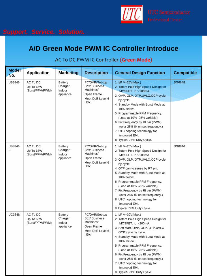
AC To DC PWM IC Controller (Green Mode)
Model
No. Application Marketing Description General Design Function Compatible
UB3846 AC To DC
Up To 65W
(Burst/PFM/PWM)
Battery
Charger
Indoor
appliance
PC/DVR/Set-top
Box/ Business
Machines/
Open Frame
Meet DoE Level 6
, Etc
1. I/P V=25V(Max.)
2. Totem Pole High Speed Design for
MOSFET. Io>200mA.
3. OVP, OLP, OTP,UVLO.OCP cycle
by cycle.
4. Standby Mode with Burst Mode at
10% below.
5. Programmable PFM Frequency.
(Load at 10% -25% variable).
6. Fix Frequency by RI pin (PWM)
(over 25% fix on set frequency.)
7. UTC hopping technology for
improved EMI.
8. Typical 74% Duty Cycle.
SG6848
UB3846
B
AC To DC
Up To 65W
(Burst/PFM/PWM)
Battery
Charger
Indoor
appliance
PC/DVR/Set-top
Box/ Business
Machines/
Open Frame
Meet DoE Level 6
, Etc
1. I/P V=25V(Max.)
2. Totem Pole High Speed Design for
MOSFET. Io>200mA.
3. OVP, OLP, OTP,UVLO.OCP cycle
by cycle.
4. OTP can to sense by RT pin.
5. Standby Mode with Burst Mode at
10% below.
6. Programmable PFM Frequency.
(Load at 10% -25% variable).
7. Fix Frequency by RI pin (PWM)
(over 25% fix on set frequency.)
8. UTC hopping technology for
improved EMI.
9.Typical 74% Duty Cycle.
SG6846
UC3848 AC To DC
Up To 65W
(Burst/PFM/PWM)
Battery
Charger
Indoor
appliance
PC/DVR/Set-top
Box/ Business
Machines/
Open Frame
Meet DoE Level 6
, Etc
1. I/P V=30V(Max.)
2. Totem Pole High Speed Design for
MOSFET. Io>200mA.
3. Soft start, OVP, OLP, OTP,UVLO
OCP cycle by cycle.
4. Standby Mode with Burst Mode at
10% below.
5. Programmable PFM Frequency.
(Load at 10% -25% variable).
6. Fix Frequency by RI pin (PWM)
(over 25% fix on set frequency.)
7. UTC hopping technology for
improved EMI.
8. Typical 74% Duty Cycle.
UTC Semiconductor
Professional Design
Support. Service. Solution.
A/D Green Mode PWM IC Controller Introduce
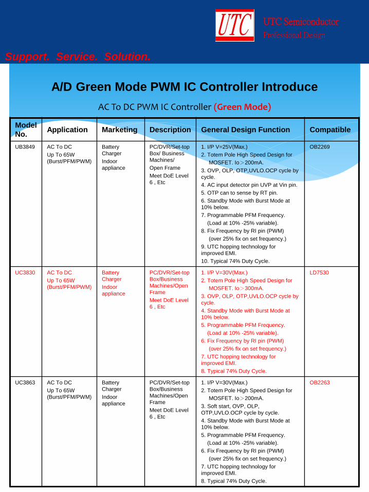
AC To DC PWM IC Controller (Green Mode)
Model
No. Application Marketing Description General Design Function Compatible
UB3849 AC To DC
Up To 65W
(Burst/PFM/PWM)
Battery
Charger
Indoor
appliance
PC/DVR/Set-top
Box/ Business
Machines/
Open Frame
Meet DoE Level
6 , Etc
1. I/P V=25V(Max.)
2. Totem Pole High Speed Design for
MOSFET. Io>200mA.
3. OVP, OLP, OTP,UVLO.OCP cycle by
cycle.
4. AC input detector pin UVP at Vin pin.
5. OTP can to sense by RT pin.
6. Standby Mode with Burst Mode at
10% below.
7. Programmable PFM Frequency.
(Load at 10% -25% variable).
8. Fix Frequency by RI pin (PWM)
(over 25% fix on set frequency.)
9. UTC hopping technology for
improved EMI.
10. Typical 74% Duty Cycle.
OB2269
UC3830 AC To DC
Up To 65W
(Burst/PFM/PWM)
Battery
Charger
Indoor
appliance
PC/DVR/Set-top
Box/Business
Machines/Open
Frame
Meet DoE Level
6 , Etc
1. I/P V=30V(Max.)
2. Totem Pole High Speed Design for
MOSFET. Io>300mA.
3. OVP, OLP, OTP,UVLO.OCP cycle by
cycle.
4. Standby Mode with Burst Mode at
10% below.
5. Programmable PFM Frequency.
(Load at 10% -25% variable).
6. Fix Frequency by RI pin (PWM)
(over 25% fix on set frequency.)
7. UTC hopping technology for
improved EMI.
8. Typical 74% Duty Cycle.
LD7530
UC3863
AC To DC
Up To 65W
(Burst/PFM/PWM)
Battery
Charger
Indoor
appliance
PC/DVR/Set-top
Box/Business
Machines/Open
Frame
Meet DoE Level
6 , Etc
1. I/P V=30V(Max.)
2. Totem Pole High Speed Design for
MOSFET. Io>200mA.
3. Soft start, OVP, OLP,
OTP,UVLO.OCP cycle by cycle.
4. Standby Mode with Burst Mode at
10% below.
5. Programmable PFM Frequency.
(Load at 10% -25% variable).
6. Fix Frequency by RI pin (PWM)
(over 25% fix on set frequency.)
7. UTC hopping technology for
improved EMI.
8. Typical 74% Duty Cycle.
OB2263
UTC Semiconductor
Professional Design
Support. Service. Solution.
A/D Green Mode PWM IC Controller Introduce
AC To DC PWM IC Controller (Green Mode)
UTC Lead
Trend On Bright RICHTEK GRENERGY 賽威
UC3863 LD7535
LD7535A OB2263 R7731
GR8830
GR8836 SF1531
PIN
Assignment
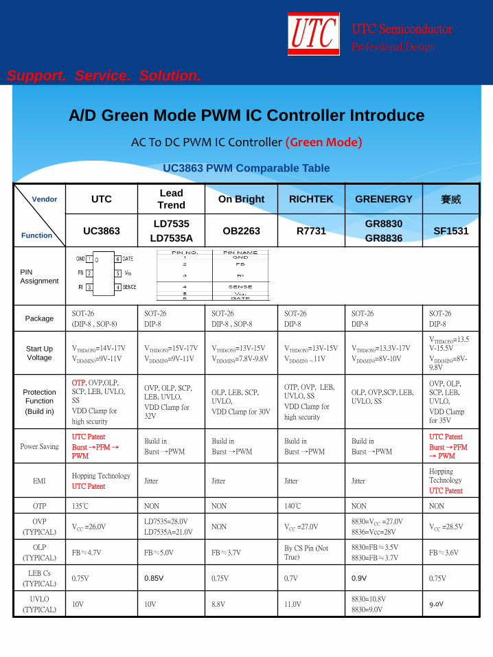
Package SOT-26
(DIP-8 , SOP-8)
SOT-26
DIP-8
SOT-26
DIP-8 , SOP-8
SOT-26
DIP-8
SOT-26
DIP-8
SOT-26
DIP-8
Start Up
Voltage
VTHD(ON)=14V-17V
VDD(MIN)=9V-11V
VTHD(ON)=15V-17V
VDD(MIN)=9V-11V
VTHD(ON)=13V-15V
VDD(MIN)=7.8V-9.8V
VTHD(ON)=13V-15V
VDD(MIN) ≒11V
VTHD(ON)=13.3V-17V
VDD(MIN)=8V-10V
VTHD(ON)=13.5V-15.5V
VDD(MIN)=8V-9.8V
Protection
Function
(Build in)
OTP, OVP,OLP, SCP, LEB, UVLO, SS
VDD Clamp for
high security
OVP, OLP, SCP, LEB, UVLO,
VDD Clamp for 32V
OLP, LEB, SCP, UVLO,
VDD Clamp for 30V
OTP, OVP, LEB, UVLO, SS
VDD Clamp for
high security
OLP, OVP,SCP, LEB, UVLO, SS
OVP, OLP, SCP, LEB, UVLO,
VDD Clamp for 35V
Power Saving
UTC Patent
Burst →PFM → PWM
Build in
Burst →PWM
Build in
Burst →PWM
Build in
Burst →PWM
Build in
Burst →PWM
UTC Patent
Burst →PFM → PWM
EMI Hopping Technology
UTC Patent Jitter Jitter Jitter Jitter
Hopping Technology
UTC Patent
OTP 135℃ NON NON 140℃ NON NON
OVP
(TYPICAL) VCC =26.0V
LD7535=28.0V
LD7535A=21.0V NON VCC =27.0V
8830=VCC =27.0V
8836=Vcc=28V VCC =28.5V
OLP
(TYPICAL) FB≒4.7V FB≒5.0V FB≒3.7V
By CS Pin (Not True)
8830=FB≒3.5V
8830=FB≒3.7V FB≒3.6V
LEB Cs
(TYPICAL) 0.75V 0.85V 0.75V 0.7V 0.9V 0.75V
UVLO
(TYPICAL) 10V 10V 8.8V 11.0V
8830=10.8V
8830=9.0V 9.0V
UTC Semiconductor
Professional Design
Support. Service. Solution.
A/D Green Mode PWM IC Controller Introduce
UC3863 PWM Comparable Table
Vendor
Function

AC To DC PWM IC Controller (Green Mode)
UTC Lead
Trend On Bright RICHTEK GRENERGY 賽威
UC3863 LD7535
LD7535A OB2263 R7731
GR8830
GR8836 SF1531
Function Compare Instruction
OTP Yes X X Yes X X
OVP Yes Yes X Yes Yes Yes
OLP Yes Yes Yes X Yes Yes
SCP Yes Yes Yes Danger Yes Yes
LEB Yes Yes Yes Yes Yes Yes
UVLO Yes Yes Yes Yes Yes Yes
SS Yes X X Yes Yes Yes
VDD
Clamp Yes Yes Yes Yes X Yes
Electrical Characteristics Function Compare Instruction
Efficiency Best Generally Generally Generally Generally Best
Power
Saving
UTC Patent
Burst →PFM → PWM
Build in
Burst →PWM
Build in
Burst →PWM
Build in
Burst →PWM
Build in
Burst →PWM
UTC Patent
Burst →PFM → PWM
EMI Hopping Technology
UTC Patent Jitter Jitter Jitter Jitter
Hopping Technology
UTC Patent
Start Up
Istr <5uA <20uA <20uA <30uA <15uA <5uA
Design Capability Compare Instruction
O/P Watts Up to 65W Up to 65W 36W Up to 65W 36W 36W
UTC Semiconductor
Professional Design
Support. Service. Solution.
A/D Green Mode PWM IC Controller Introduce
UTC Electrical Characteristics Excellence
Vendor
Function
AC To DC PWM IC Controller (Green Mode)
UTC On Bright Lead Trend 賽威
UC3873 OB2273 LD7536 SF5545
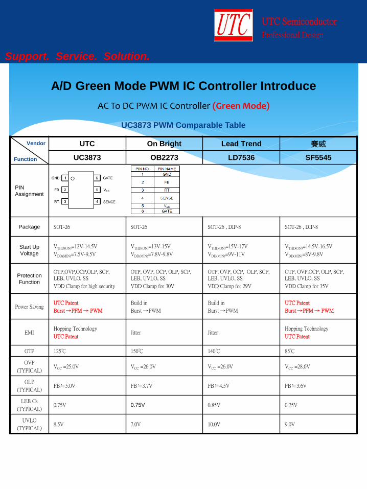
PIN
Assignment
Package SOT-26 SOT-26 SOT-26 , DIP-8 SOT-26 , DIP-8
Start Up
Voltage
VTHD(ON)=12V-14.5V
VDD(MIN)=7.5V-9.5V
VTHD(ON)=13V-15V
VDD(MIN)=7.8V-9.8V
VTHD(ON)=15V-17V
VDD(MIN)=9V-11V
VTHD(ON)=14.5V-16.5V
VDD(MIN)=8V-9.8V
Protection
Function
OTP,OVP,OCP,OLP, SCP, LEB, UVLO, SS
VDD Clamp for high security
OTP, OVP, OCP, OLP, SCP, LEB, UVLO, SS
VDD Clamp for 30V
OTP, OVP, OCP, OLP, SCP, LEB, UVLO, SS
VDD Clamp for 29V
OTP, OVP,OCP, OLP, SCP, LEB, UVLO, SS
VDD Clamp for 35V
Power Saving UTC Patent
Burst →PFM → PWM
Build in
Burst →PWM
Build in
Burst →PWM
UTC Patent
Burst →PFM → PWM
EMI Hopping Technology
UTC Patent Jitter Jitter
Hopping Technology
UTC Patent
OTP 125℃ 150℃ 140℃ 85℃
OVP
(TYPICAL) VCC =25.0V VCC =26.0V VCC =26.0V VCC =28.0V
OLP
(TYPICAL) FB≒5.0V FB≒3.7V FB≒4.5V FB≒3.6V
LEB Cs
(TYPICAL) 0.75V 0.75V 0.85V 0.75V
UVLO
(TYPICAL) 8.5V 7.0V 10.0V 9.0V
UTC Semiconductor
Professional Design
Support. Service. Solution.
A/D Green Mode PWM IC Controller Introduce
UC3873 PWM Comparable Table
Vendor
Function

AC To DC PWM IC Controller (Green Mode)
UTC On Bright Lead Trend 賽威
UC3873 OB2273 LD7536 SF5545
Electrical Characteristics Function Compare Instruction
Efficiency Best Generally Generally Best
Power
Saving
UTC Patent
Burst →PFM → PWM
Build in
Burst →PWM
Build in
Burst →PWM
UTC Patent
Burst →PFM → PWM
EMI Hopping Technology
UTC Patent Jitter Jitter
Hopping Technology
UTC Patent
Start Up
Istr <5uA <20uA <20uA <15uA
Design Capability Compare Instruction
O/P Watts Up to 65W 36W Up to 65W 36W
UTC Semiconductor
Professional Design
Support. Service. Solution.
A/D Green Mode PWM IC Controller Introduce
UTC Electrical Characteristics Excellence
Vendor
Function
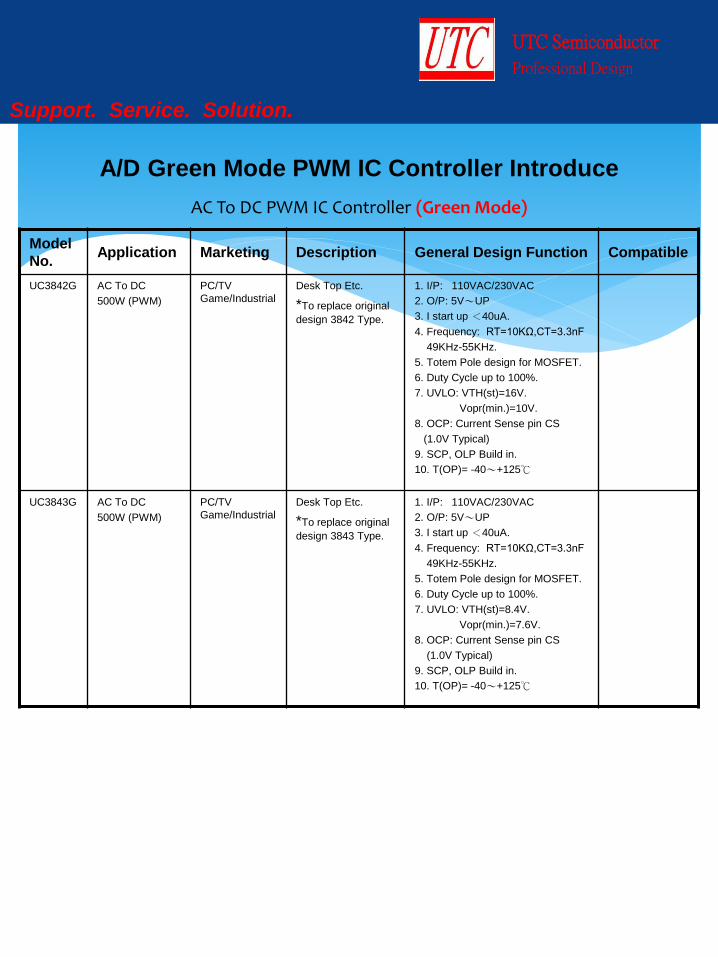
AC To DC PWM IC Controller (Green Mode)
Model
No. Application Marketing Description General Design Function Compatible
UC3842G AC To DC
500W (PWM)
PC/TV
Game/Industrial
Desk Top Etc.
*To replace original
design 3842 Type.
1. I/P: 110VAC/230VAC
2. O/P: 5V~UP
3. I start up <40uA.
4. Frequency: RT=10KΩ,CT=3.3nF
49KHz-55KHz.
5. Totem Pole design for MOSFET.
6. Duty Cycle up to 100%.
7. UVLO: VTH(st)=16V.
Vopr(min.)=10V.
8. OCP: Current Sense pin CS
(1.0V Typical)
9. SCP, OLP Build in.
10. T(OP)= -40~+125℃
UC3843G AC To DC
500W (PWM)
PC/TV
Game/Industrial
Desk Top Etc.
*To replace original
design 3843 Type.
1. I/P: 110VAC/230VAC
2. O/P: 5V~UP
3. I start up <40uA.
4. Frequency: RT=10KΩ,CT=3.3nF
49KHz-55KHz.
5. Totem Pole design for MOSFET.
6. Duty Cycle up to 100%.
7. UVLO: VTH(st)=8.4V.
Vopr(min.)=7.6V.
8. OCP: Current Sense pin CS
(1.0V Typical)
9. SCP, OLP Build in.
10. T(OP)= -40~+125℃
UTC Semiconductor
Professional Design
Support. Service. Solution.
A/D Green Mode PWM IC Controller Introduce
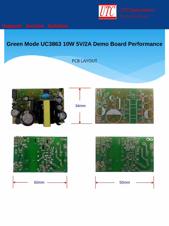
PCB LAYOUT
UTC Semiconductor
Professional Design
Support. Service. Solution.
Green Mode UC3863 10W 5V/2A Demo Board Performance
34mm
50mm 50mm
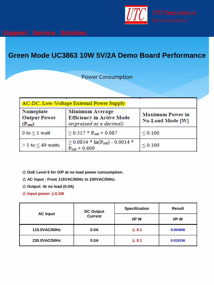
Power Consumption
UTC Semiconductor
Professional Design
Support. Service. Solution.
Green Mode UC3863 10W 5V/2A Demo Board Performance
☆ DoE Level 6 for O/P at no load power consumption.
☆ AC Input : From 115VAC/60Hz to 230VAC/50Hz.
☆ Output: At no load (0.0A)
☆ Input power ≦0.1W
AC Input DC Output
Current
Specification Result
I/P W I/P W
115.0VAC/60Hz 0.0A ≦ 0.1 0.0046W
230.0VAC/50Hz 0.0A ≦ 0.1 0.0191W

Efficiency
UTC Semiconductor
Professional Design
Support. Service. Solution.
Green Mode UC3863 10W 5V/2A Demo Board Performance
☆ Low voltage model (Po=10W).
☆ Measure at end of cable, 18AWG/1.8m.
AC Input
VAC/Hz Iout(2A)
Rule AV-EFF
(DoE Level 6)
Result
Pin (W) Pout (W) EFF. (%) AV-EFF. (%)
115.0/60
25%
78.704%
3.213 2.578 80.236
81.133 50% 6.207 5.108 82.294
75% 9.330 7.590 81.350
100% 12.426 10.022 80.653
230.0/50
25%
78.704%
3.280 2.578 78.597
80.150 50% 6.281 5.108 81.324
75% 9.442 7.589 80.375
100% 12.480 10.022 80.304
UTC Semiconductor
Professional Design
Support. Service. Solution.
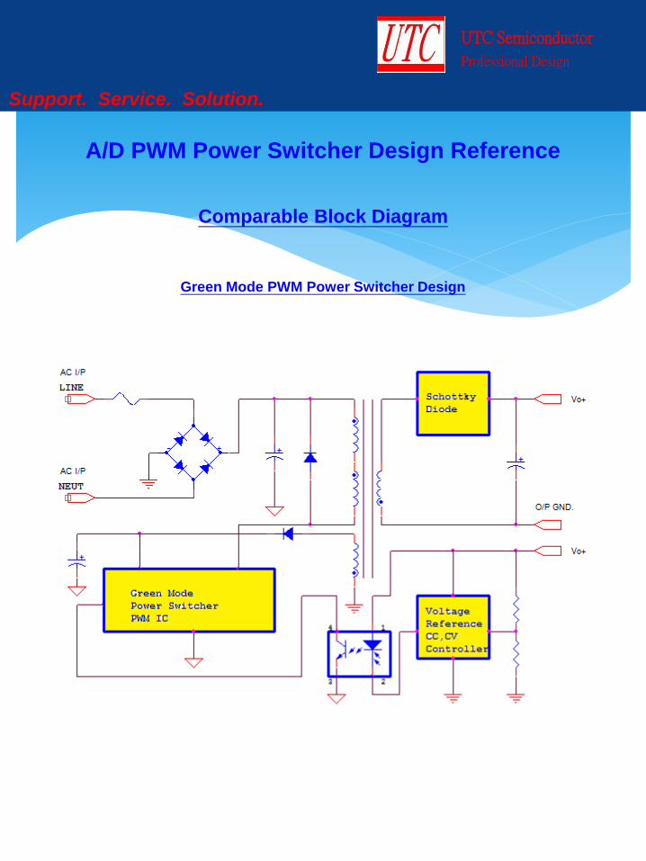
Green Mode PWM Power Switcher Design
A/D PWM Power Switcher Design Reference
Comparable Block Diagram
AC To DC PWM Power Switcher (Green Mode)
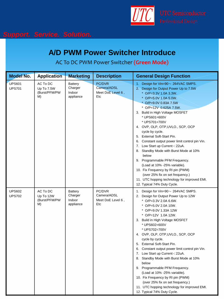
Model No. Application Marketing Description General Design Function
UPS601
UPS701
AC To DC
Up To 7.5W
(Burst/PFM/PW
M)
Battery
Charger
Indoor
appliance
PC/DVR
Camera/ADSL
Meet DoE Level 6 ,
Etc
1. Design for Vin=90~ 264VAC SMPS.
2. Design for Output Power Up to 7.5W
* O/P=3.3V 1.0A 3.3W.
* O/P=5.0V 1.0A 5.0W.
* O/P=9.0V 0.83A 7.5W
* O/P=12V 0.625A 7.5W.
3. Build in High Voltage MOSFET
* UPS601=600V
* UPS701=700V
4. OVP, OLP, OTP,UVLO., SCP, OCP
cycle by cycle.
5. External Soft-Start Pin.
6. Constant output power limit control pin Vin.
7. Low Start up Current<22uA.
8. Standby Mode with Burst Mode at 10%
below
9. Programmable PFM Frequency.
(Load at 10% -25% variable).
10. Fix Frequency by RI pin (PWM)
(over 25% fix on set frequency.)
11. UTC hopping technology for improved EMI.
12. Typical 74% Duty Cycle.
UPS602
UPS702
AC To DC
Up To 12W
(Burst/PFM/PW
M)
Battery
Charger
Indoor
appliance
PC/DVR
Camera/ADSL
Meet DoE Level 6 ,
Etc
1. Design for Vin=90~ 264VAC SMPS.
2. Design for Output Power Up to 12W
* O/P=3.3V 2.0A 6.6W.
* O/P=5.0V 2.0A 10W.
* O/P=9.0V 1.33A 12W
* O/P=12V 1.0A 12W.
3. Build in High Voltage MOSFET
* UPS602=600V
* UPS702=700V
4. OVP, OLP, OTP,UVLO., SCP, OCP
cycle by cycle.
5. External Soft-Start Pin.
6. Constant output power limit control pin Vin.
7. Low Start up Current<22uA.
8. Standby Mode with Burst Mode at 10%
below
9. Programmable PFM Frequency.
(Load at 10% -25% variable).
10. Fix Frequency by RI pin (PWM)
(over 25% fix on set frequency.)
11. UTC hopping technology for improved EMI.
12. Typical 74% Duty Cycle.
UTC Semiconductor
Professional Design
Support. Service. Solution.
A/D PWM Power Switcher Introduce
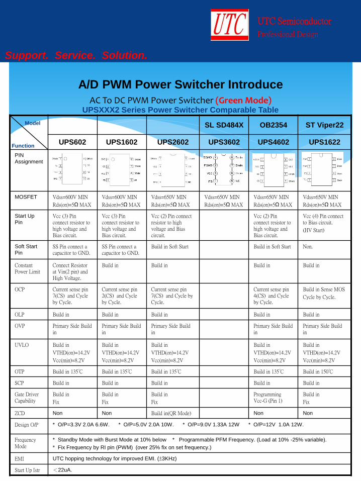
AC To DC PWM Power Switcher (Green Mode)
SL SD484X OB2354 ST Viper22
UPS602 UPS1602 UPS2602 UPS3602 UPS4602 UPS1622
PIN
Assignment
MOSFET Vdss=600V MIN
Rds(on)=5Ω MAX
Vdss=600V MIN
Rds(on)=5Ω MAX
Vdss=650V MIN
Rds(on)=5Ω MAX
Vdss=650V MIN
Rds(on)=5Ω MAX
Vdss=650V MIN
Rds(on)=5Ω MAX
Vdss=650V MIN
Rds(on)=5Ω MAX
Start Up
Pin
Vcc (3) Pin connect resistor to high voltage and Bias circuit.
Vcc (3) Pin connect resistor to high voltage and Bias circuit.
Vcc (2) Pin connect resistor to high voltage and Bias circuit.
Vcc (2) Pin connect resistor to high voltage and Bias circuit.
Vcc (4) Pin connect to Bias circuit.
(HV Start)
Soft Start
Pin
SS Pin connect a capacitor to GND.
SS Pin connect a capacitor to GND.
Build in Soft Start Build in Soft Start Non.
Constant Power Limit
Connect Resistor at Vin(2 pin) and High Voltage.
Build in Build in
Build in Build in
OCP Current sense pin 7(CS) and Cycle by Cycle.
Current sense pin 2(CS) and Cycle by Cycle.
Current sense pin 7(CS) and Cycle by Cycle.
Current sense pin 4(CS) and Cycle by Cycle.
Build in Sense MOS
Cycle by Cycle.
OLP Build in Build in Build in Build in Build in
OVP Primary Side Build in
Primary Side Build in
Primary Side Build in
Primary Side Build in
Primary Side Build in
UVLO Build in
VTHD(on)=14.2V
Vcc(min)=8.2V
Build in
VTHD(on)=14.2V
Vcc(min)=8.2V
Build in
VTHD(on)=14.2V
Vcc(min)=8.2V
Build in
VTHD(on)=14.2V
Vcc(min)=8.2V
Build in
VTHD(on)=14.2V
Vcc(min)=8.2V
OTP Build in 135℃ Build in 135℃ Build in 135℃ Build in 135℃ Build in 150℃
SCP Build in Build in Build in Build in Build in
Gate Driver Capability
Build in
Fix
Build in
Fix
Build in
Fix
Programming Vcc-G (Pin 1)
Build in
Fix
ZCD Non Non Build in(QR Mode) Non Non
Design O/P * O/P=3.3V 2.0A 6.6W. * O/P=5.0V 2.0A 10W. * O/P=9.0V 1.33A 12W * O/P=12V 1.0A 12W.
Frequency Mode
* Standby Mode with Burst Mode at 10% below * Programmable PFM Frequency. (Load at 10% -25% variable).
* Fix Frequency by RI pin (PWM) (over 25% fix on set frequency.)
EMI UTC hopping technology for improved EMI. (±3KHz)
Start Up Istr <22uA.
UTC Semiconductor
Professional Design
Support. Service. Solution.
A/D PWM Power Switcher Introduce
UPSXXX2 Series Power Switcher Comparable Table
Model
Function
AC To DC PWM Power Switcher (Green Mode)
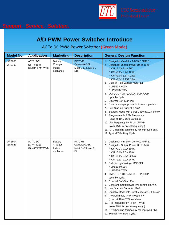
Model No. Application Marketing Description General Design Function
UPS603
UPS703
AC To DC
Up To 15W
(Burst/PFM/PWM)
Battery
Charger
Indoor
appliance
PC/DVR
Camera/ADSL
Meet DoE Level 6 ,
Etc
1. Design for Vin=90~ 264VAC SMPS.
2. Design for Output Power Up to 15W
* O/P=3.3V 2.4A 8W.
* O/P=5.0V 2.4A 12W.
* O/P=9.0V 1.67A 15W
* O/P=12V 1.25A 15W.
3. Build in High Voltage MOSFET
* UPS603=600V
* UPS703=700V
4. OVP, OLP, OTP,UVLO., SCP, OCP
cycle by cycle.
5. External Soft-Start Pin.
6. Constant output power limit control pin Vin.
7. Low Start up Current<22uA.
8. Standby Mode with Burst Mode at 10% below
9. Programmable PFM Frequency.
(Load at 10% -25% variable).
10. Fix Frequency by RI pin (PWM)
(over 25% fix on set frequency.)
11. UTC hopping technology for improved EMI.
12. Typical 74% Duty Cycle.
UPS604
UPS704
AC To DC
Up To 24W
(Burst/PFM/PWM)
Battery
Charger
Indoor
appliance
PC/DVR
Camera/ADSL
Meet DoE Level 6 ,
Etc
1. Design for Vin=90~ 264VAC SMPS.
2. Design for Output Power Up to 24W
* O/P=3.3V 3.0A 10W.
* O/P=5.0V 3.0A 15W.
* O/P=9.0V 2.5A 22.5W
* O/P=12V 2.0A 24W.
3. Build in High Voltage MOSFET
* UPS604=600V
* UPS704=700V
4. OVP, OLP, OTP,UVLO., SCP, OCP
cycle by cycle.
5. External Soft-Start Pin.
6. Constant output power limit control pin Vin.
7. Low Start up Current<22uA.
8. Standby Mode with Burst Mode at 10% below
9. Programmable PFM Frequency.
(Load at 10% -25% variable).
10. Fix Frequency by RI pin (PWM)
(over 25% fix on set frequency.)
11. UTC hopping technology for improved EMI.
12. Typical 74% Duty Cycle.
UTC Semiconductor
Professional Design
Support. Service. Solution.
A/D PWM Power Switcher Introduce
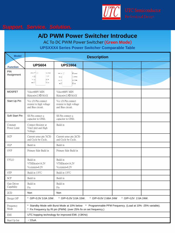
AC To DC PWM Power Switcher (Green Mode)
Description
UPS604 UPS1604
PIN
Assignment
MOSFET Vdss=600V MIN
Rds(on)=2.5Ω MAX
Vdss=600V MIN
Rds(on)=2.5Ω MAX
Start Up Pin Vcc (3) Pin connect resistor to high voltage and Bias circuit.
Vcc (3) Pin connect resistor to high voltage and Bias circuit.
Soft Start Pin SS Pin connect a capacitor to GND.
SS Pin connect a capacitor to GND.
Constant Power Limit
Connect Resistor at Vin(2 pin) and High Voltage.
Build in
OCP Current sense pin 7(CS) and Cycle by Cycle.
Current sense pin 2(CS) and Cycle by Cycle.
OLP Build in Build in
OVP Primary Side Build in Primary Side Build in
UVLO Build in
VTHD(on)=14.2V
Vcc(min)=8.2V
Build in
VTHD(on)=14.2V
Vcc(min)=8.2V
OTP Build in 135℃ Build in 135℃
SCP Build in Build in
Gate Driver Capability
Build in
Fix
Build in
Fix
ZCD Non Non
Design O/P * O/P=3.3V 3.0A 10W. * O/P=5.0V 3.0A 15W. * O/P=9.0V 2.66A 24W * O/P=12V 2.0A 24W.
Frequency Mode
* Standby Mode with Burst Mode at 10% below * Programmable PFM Frequency. (Load at 10% -25% variable).
* Fix Frequency by RI pin (PWM) (over 25% fix on set frequency.)
EMI UTC hopping technology for improved EMI. (±3KHz)
Start Up Istr <22uA.
UTC Semiconductor
Professional Design
Support. Service. Solution.
A/D PWM Power Switcher Introduce
UPSXXX4 Series Power Switcher Comparable Table
Model
Function
UTC Semiconductor
Professional Design
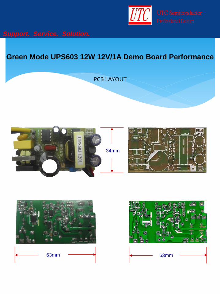
Support. Service. Solution.
Green Mode UPS603 12W 12V/1A Demo Board Performance
PCB LAYOUT
34mm
63mm 63mm
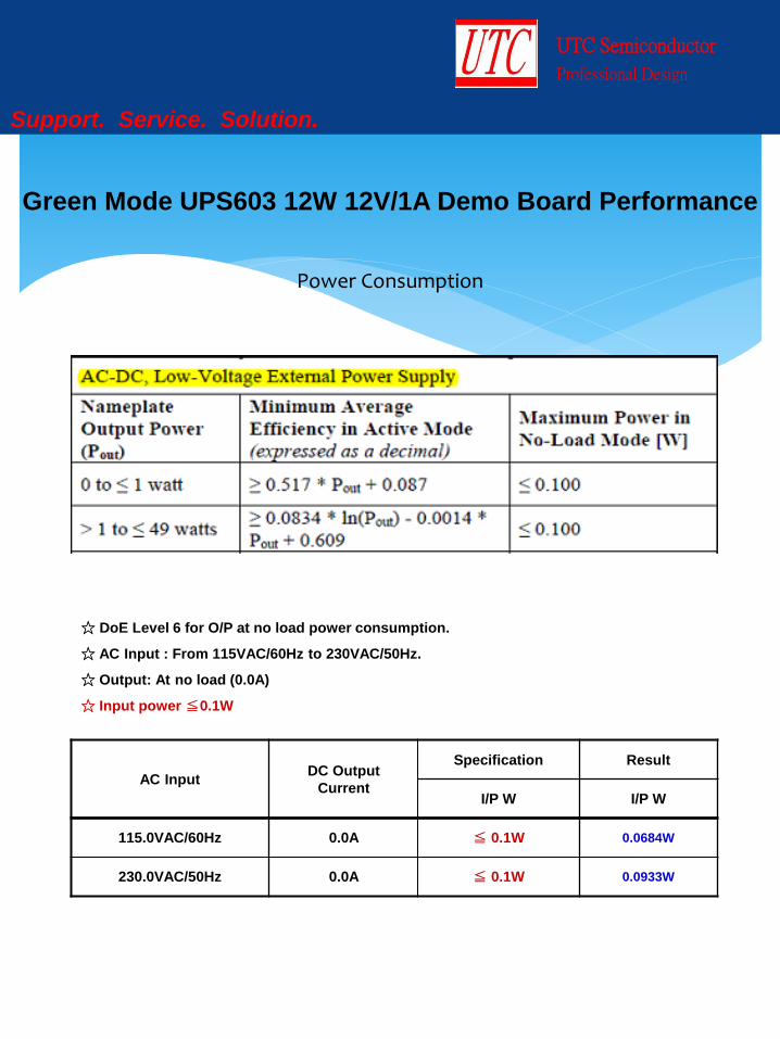
Power Consumption
UTC Semiconductor
Professional Design
Support. Service. Solution.
Green Mode UPS603 12W 12V/1A Demo Board Performance
☆ DoE Level 6 for O/P at no load power consumption.
☆ AC Input : From 115VAC/60Hz to 230VAC/50Hz.
☆ Output: At no load (0.0A)
☆ Input power ≦0.1W
AC Input DC Output
Current
Specification Result
I/P W I/P W
115.0VAC/60Hz 0.0A ≦ 0.1W 0.0684W
230.0VAC/50Hz 0.0A ≦ 0.1W 0.0933W
Efficiency
UTC Semiconductor
Professional Design
Support. Service. Solution.
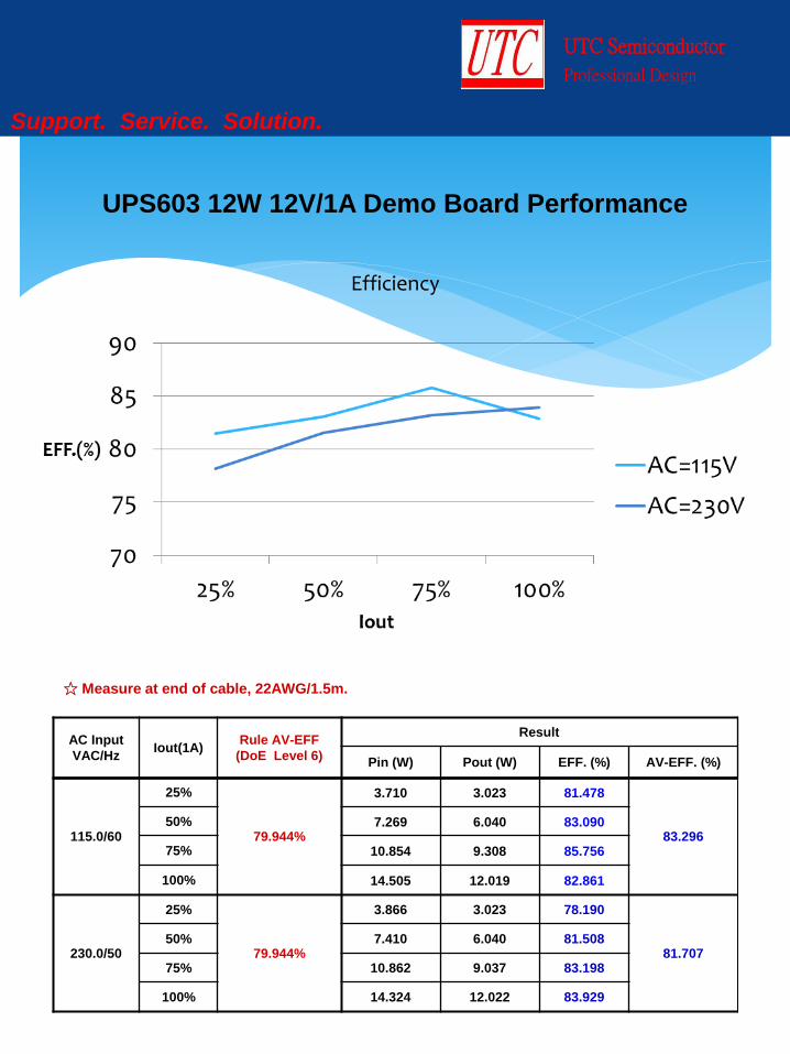
☆ Measure at end of cable, 22AWG/1.5m.
AC Input
VAC/Hz Iout(1A)
Rule AV-EFF
(DoE Level 6)
Result
Pin (W) Pout (W) EFF. (%) AV-EFF. (%)
115.0/60
25%
79.944%
3.710 3.023 81.478
83.296 50% 7.269 6.040 83.090
75% 10.854 9.308 85.756
100% 14.505 12.019 82.861
230.0/50
25%
79.944%
3.866 3.023 78.190
81.707 50% 7.410 6.040 81.508
75% 10.862 9.037 83.198
100% 14.324 12.022 83.929
UPS603 12W 12V/1A Demo Board Performance

UTC Semiconductor
Professional Design
Support. Service. Solution.
Power Factor Controller Design Reference
Comparable Block Diagram
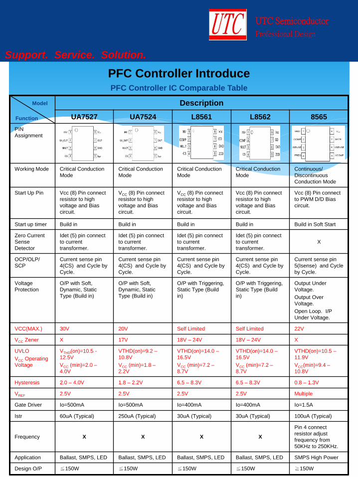
Description
UA7527 UA7524 L8561 L8562 8565
PIN
Assignment
Working Mode Critical Conduction
Mode
Critical Conduction
Mode
Critical Conduction
Mode
Critical Conduction
Mode
Continuous/
Discontinuous
Conduction Mode
Start Up Pin Vcc (8) Pin connect
resistor to high
voltage and Bias
circuit.
VCC (8) Pin connect
resistor to high
voltage and Bias
circuit.
VCC (8) Pin connect
resistor to high
voltage and Bias
circuit.
Vcc (8) Pin connect
resistor to high
voltage and Bias
circuit.
Vcc (8) Pin connect
to PWM D/D Bias
circuit.
Start up timer Build in Build in Build in Build in Build in Soft Start
Zero Current
Sense
Detector
Idet (5) pin connect
to current
transformer.
Idet (5) pin connect
to current
transformer.
Idet (5) pin connect
to current
transformer.
Idet (5) pin connect
to current
transformer.
X
OCP/OLP/
SCP
Current sense pin
4(CS) and Cycle by
Cycle.
Current sense pin
4(CS) and Cycle by
Cycle.
Current sense pin
4(CS) and Cycle by
Cycle.
Current sense pin
4(CS) and Cycle by
Cycle.
Current sense pin
5(Isense) and Cycle
by Cycle.
Voltage
Protection
O/P with Soft,
Dynamic, Static
Type (Build in)
O/P with Soft,
Dynamic, Static
Type (Build in)
O/P with Triggering,
Static Type (Build
in)
O/P with Triggering,
Static Type (Build
in)
Output Under
Voltage.
Output Over
Voltage.
Open Loop. I/P
Under Voltage.
VCC(MAX.) 30V 20V Self Limited Self Limited 22V
VCC Zener X 17V 18V – 24V 18V – 24V X
UVLO
VCC Operating
Voltage
VTHD(on)=10.5 -
12.5V
VCC (min)=2.0 –
4.0V
VTHD(on)=9.2 –
10.8V
VCC (min)=1.8 –
2.2V
VTHD(on)=14.0 –
16.5V
VCC (min)=7.2 –
8.7V
VTHD(on)=14.0 –
16.5V
VCC (min)=7.2 –
8.7V
VTHD(on)=10.5 –
11.9V
VCC(min)=9.4 –
10.8V
Hysteresis 2.0 – 4.0V 1.8 – 2.2V 6.5 – 8.3V 6.5 – 8.3V 0.8 – 1.3V
VREF 2.5V 2.5V 2.5V 2.5V Multiple
Gate Driver Io=500mA Io=500mA Io=400mA Io=400mA Io=1.5A
Istr 60uA (Typical) 250uA (Typical) 30uA (Typical) 30uA (Typical) 100uA (Typical)
Frequency X X X X
Pin 4 connect
resistor adjust
frequency from
50KHz to 250KHz.
Application Ballast, SMPS, LED Ballast, SMPS, LED Ballast, SMPS, LED Ballast, SMPS, LED SMPS High Power
Design O/P ≦150W ≦150W ≦150W ≦150W ≧150W
UTC Semiconductor
Professional Design
Support. Service. Solution.
PFC Controller Introduce
Model
Function
PFC Controller IC Comparable Table
UTC Semiconductor
Professional Design
Support. Service. Solution.
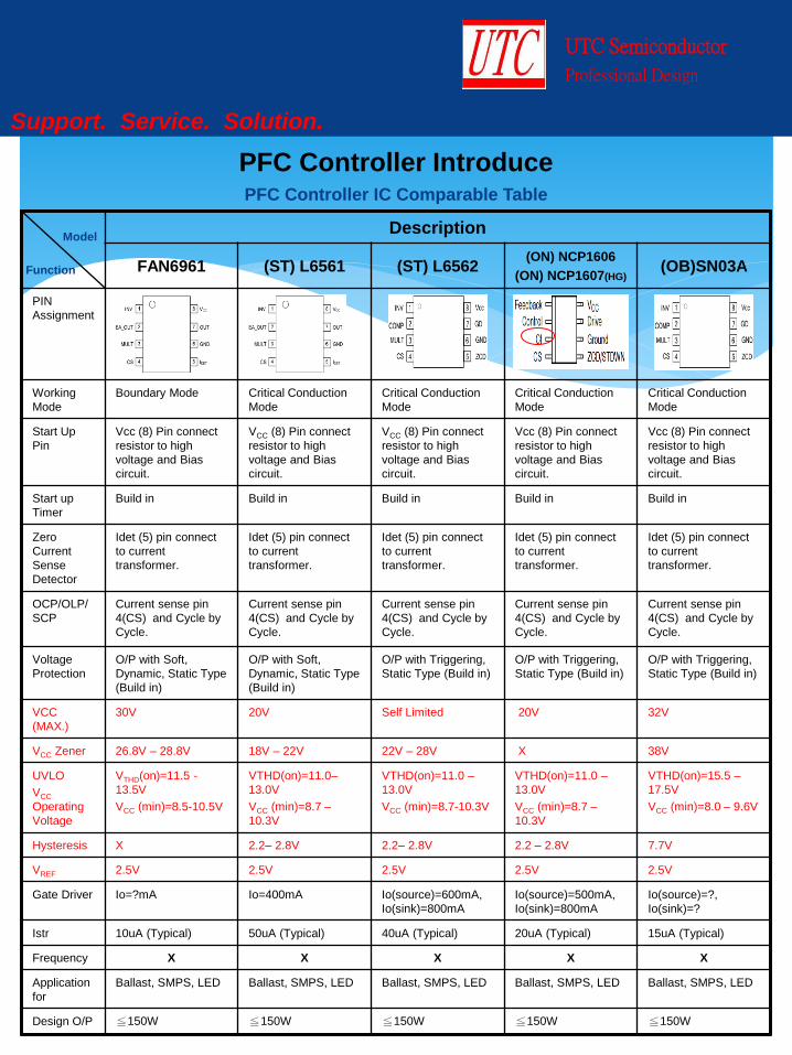
PFC Controller Introduce PFC Controller IC Comparable Table
Description
FAN6961 (ST) L6561 (ST) L6562 (ON) NCP1606
(ON) NCP1607(HG) (OB)SN03A
PIN
Assignment
Working
Mode
Boundary Mode Critical Conduction
Mode
Critical Conduction
Mode
Critical Conduction
Mode
Critical Conduction
Mode
Start Up
Pin
Vcc (8) Pin connect
resistor to high
voltage and Bias
circuit.
VCC (8) Pin connect
resistor to high
voltage and Bias
circuit.
VCC (8) Pin connect
resistor to high
voltage and Bias
circuit.
Vcc (8) Pin connect
resistor to high
voltage and Bias
circuit.
Vcc (8) Pin connect
resistor to high
voltage and Bias
circuit.
Start up
Timer
Build in Build in Build in Build in Build in
Zero
Current
Sense
Detector
Idet (5) pin connect
to current
transformer.
Idet (5) pin connect
to current
transformer.
Idet (5) pin connect
to current
transformer.
Idet (5) pin connect
to current
transformer.
Idet (5) pin connect
to current
transformer.
OCP/OLP/
SCP
Current sense pin
4(CS) and Cycle by
Cycle.
Current sense pin
4(CS) and Cycle by
Cycle.
Current sense pin
4(CS) and Cycle by
Cycle.
Current sense pin
4(CS) and Cycle by
Cycle.
Current sense pin
4(CS) and Cycle by
Cycle.
Voltage
Protection
O/P with Soft,
Dynamic, Static Type
(Build in)
O/P with Soft,
Dynamic, Static Type
(Build in)
O/P with Triggering,
Static Type (Build in)
O/P with Triggering,
Static Type (Build in)
O/P with Triggering,
Static Type (Build in)
VCC
(MAX.)
30V 20V Self Limited 20V 32V
VCC Zener 26.8V – 28.8V 18V – 22V 22V – 28V X 38V
UVLO
VCC
Operating
Voltage
VTHD(on)=11.5 -
13.5V
VCC (min)=8.5-10.5V
VTHD(on)=11.0–
13.0V
VCC (min)=8.7 –
10.3V
VTHD(on)=11.0 –
13.0V
VCC (min)=8.7-10.3V
VTHD(on)=11.0 –
13.0V
VCC (min)=8.7 –
10.3V
VTHD(on)=15.5 –
17.5V
VCC (min)=8.0 – 9.6V
Hysteresis X 2.2– 2.8V 2.2– 2.8V 2.2 – 2.8V 7.7V
VREF 2.5V 2.5V 2.5V 2.5V 2.5V
Gate Driver Io=?mA Io=400mA Io(source)=600mA,
Io(sink)=800mA
Io(source)=500mA,
Io(sink)=800mA
Io(source)=?,
Io(sink)=?
Istr 10uA (Typical) 50uA (Typical) 40uA (Typical) 20uA (Typical) 15uA (Typical)
Frequency X X X X X
Application
for
Ballast, SMPS, LED Ballast, SMPS, LED Ballast, SMPS, LED Ballast, SMPS, LED Ballast, SMPS, LED
Design O/P ≦150W ≦150W ≦150W ≦150W ≦150W
Model
Function
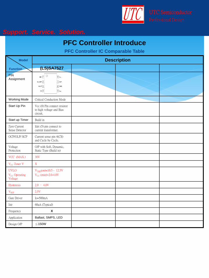
Description
(LS)SA7527
PIN
Assignment
Working Mode Critical Conduction Mode
Start Up Pin Vcc (8) Pin connect resistor to high voltage and Bias circuit.
Start up Timer Build in
Zero Current Sense Detector
Idet (5) pin connect to current transformer.
OCP/OLP/ SCP Current sense pin 4(CS) and Cycle by Cycle.
Voltage Protection
O/P with Soft, Dynamic, Static Type (Build in)
VCC (MAX.) 30V
VCC Zener V X
UVLO
VCC Operating Voltage
VTHD(on)=10.5 - 12.5V
VCC (min)=2.0-4.0V
Hysteresis 2.0 – 4.0V
VREF 2.5V
Gate Driver Io=500mA
Istr 60uA (Typical)
Frequency X
Application Ballast, SMPS, LED
Design O/P ≦150W
UTC Semiconductor
Professional Design
Support. Service. Solution.
PFC Controller Introduce PFC Controller IC Comparable Table
Model
Function

UTC Semiconductor
Professional Design
Support. Service. Solution.
UA7527 20W 27V/0.75A Demo Board Performance
PCB LAYOUT
250mm
18mm
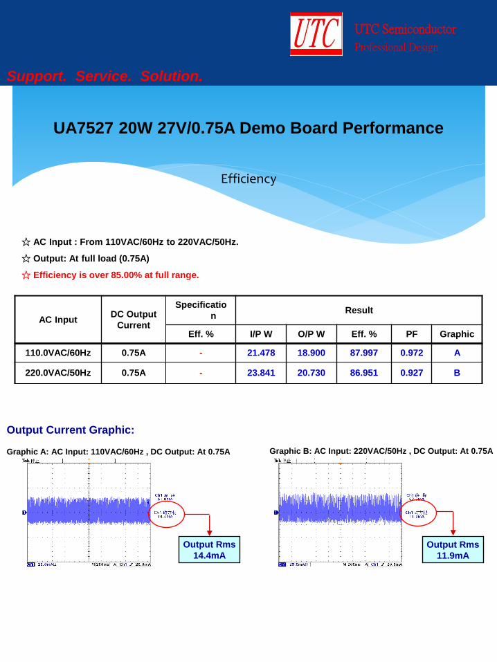
Efficiency
UTC Semiconductor
Professional Design
Support. Service. Solution.
Output Current Graphic:
Graphic B: AC Input: 220VAC/50Hz , DC Output: At 0.75A
Output Rms
14.4mA
Graphic A: AC Input: 110VAC/60Hz , DC Output: At 0.75A
Output Rms
11.9mA
UA7527 20W 27V/0.75A Demo Board Performance
☆ AC Input : From 110VAC/60Hz to 220VAC/50Hz.
☆ Output: At full load (0.75A)
☆ Efficiency is over 85.00% at full range.
AC Input DC Output
Current
Specificatio
n Result
Eff. % I/P W O/P W Eff. % PF Graphic
110.0VAC/60Hz 0.75A - 21.478 18.900 87.997 0.972 A
220.0VAC/50Hz 0.75A - 23.841 20.730 86.951 0.927 B
UTC Semiconductor
Professional Design
Support. Service. Solution.
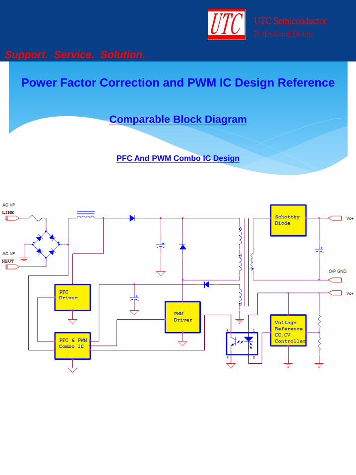
Power Factor Correction and PWM IC Design Reference
Comparable Block Diagram
PFC And PWM Combo IC Design
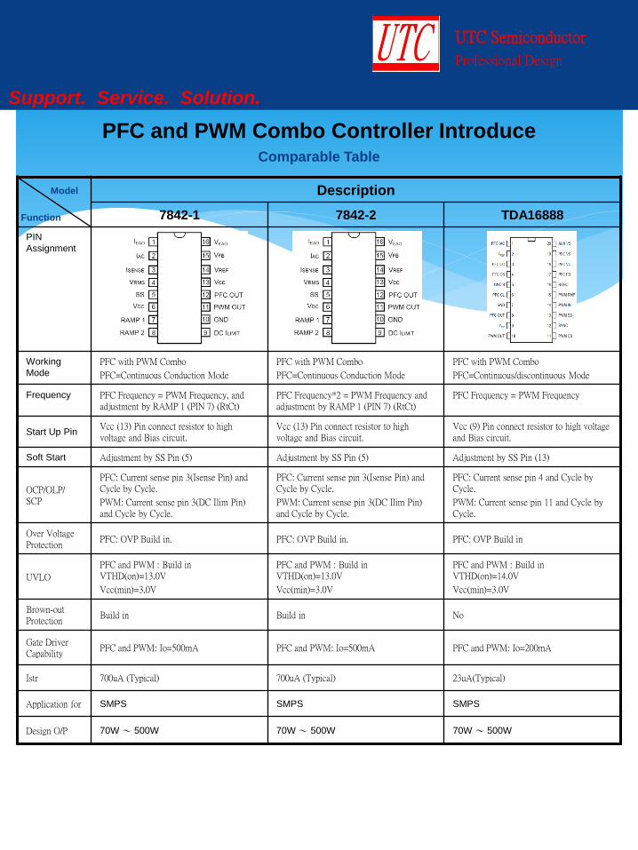
Description
7842-1 7842-2 TDA16888
PIN
Assignment
Working
Mode
PFC with PWM Combo
PFC=Continuous Conduction Mode
PFC with PWM Combo
PFC=Continuous Conduction Mode
PFC with PWM Combo
PFC=Continuous/discontinuous Mode
Frequency PFC Frequency = PWM Frequency, and adjustment by RAMP 1 (PIN 7) (RtCt)
PFC Frequency*2 = PWM Frequency and adjustment by RAMP 1 (PIN 7) (RtCt)
PFC Frequency = PWM Frequency
Start Up Pin Vcc (13) Pin connect resistor to high voltage and Bias circuit.
Vcc (13) Pin connect resistor to high voltage and Bias circuit.
Vcc (9) Pin connect resistor to high voltage and Bias circuit.
Soft Start Adjustment by SS Pin (5) Adjustment by SS Pin (5) Adjustment by SS Pin (13)
OCP/OLP/ SCP
PFC: Current sense pin 3(Isense Pin) and Cycle by Cycle.
PWM: Current sense pin 3(DC Ilim Pin) and Cycle by Cycle.
PFC: Current sense pin 3(Isense Pin) and Cycle by Cycle.
PWM: Current sense pin 3(DC Ilim Pin) and Cycle by Cycle.
PFC: Current sense pin 4 and Cycle by Cycle.
PWM: Current sense pin 11 and Cycle by Cycle.
Over Voltage Protection
PFC: OVP Build in. PFC: OVP Build in. PFC: OVP Build in
UVLO
PFC and PWM : Build in VTHD(on)=13.0V
Vcc(min)=3.0V
PFC and PWM : Build in VTHD(on)=13.0V
Vcc(min)=3.0V
PFC and PWM : Build in VTHD(on)=14.0V
Vcc(min)=3.0V
Brown-out Protection
Build in Build in No
Gate Driver Capability
PFC and PWM: Io=500mA PFC and PWM: Io=500mA PFC and PWM: Io=200mA
Istr 700uA (Typical) 700uA (Typical) 23uA(Typical)
Application for SMPS SMPS SMPS
Design O/P 70W ~ 500W 70W ~ 500W 70W ~ 500W
UTC Semiconductor
Professional Design
Support. Service. Solution.
PFC and PWM Combo Controller Introduce Comparable Table
Model
Function
Sales and Design Assistance from UTC
Power Adaptor Total Solution
UTC Semiconductor
Professional Design
Support. Service. Solution.
Http://www.unisonic.com.tw


![Aalborg Universitet Stability Analysis of Digital-Controlled Single-Phase … · extended to the other switching converters like PWM inverters [29]-[34], power factor correction (PFC)](https://img.pdfslide.net/doc/110x75/5f9568c0f4f8f34fd31e157c/aalborg-universitet-stability-analysis-of-digital-controlled-single-phase-extended.jpg)