Embed Size (px)
Citation preview

Fuzzy Auto Tuning Alarm Output Retransmission Output Multi Input•Output External Contact Input Ramp soak function Heating / Cooling
Zone PID Group PID Power supply for sensor Output Limits Interface (RS485 / 422) 3 Set points Heater break alarms
(HBA1, HBA2) IP65 Front facia
HHiigghh AAccccuurraaccyy 00..11 ccllaassss 225500mmss
FFeeaattuurreess
PX SeriesPX Series

IINNSSTTRRUUCCTTIIOONN MMAANNUUAALL
Thank you for the purchase of HHAANNYYOOUUNNGG product.
Please read this manual carefully.
PX SeriesProcess Controller
PPXX99 PPXX22 PPXX77 PPXX33

CONTENTS
1. SAFETY INFORMATION2. INSTRUCTION 3. ORDERING INFORMATION4. SPECIFICATION5.DIMENSIONS & PANEL CUTOUT6. TERMINAL ARRANGEMENT7. NAME & FUNCTION8. TABEL OF SETTING ITEMS9. SETTING METHOD10. CONTROL GROUP11. INPUT GROUP SETTING12. OUTPUT GROUP SETTING13. SET VALUE GROUP SETTING14. PROGRAM GROUP SETTING15. AUTO TUNING16. P.I.D GROUP17. ALARM GROUP SETTING18. RETRANSMISSION GROUP19. COMMUNICATION20.HEATER BREAKALARM GROUP21. REMOTE INPUT GROUP
P. 3P. 5P. 5P. 6P. 10P. 11P. 12P. 13P. 15P. 16P. 17P. 19P. 20P. 21P. 22P. 23P. 24P. 25P. 26P. 27P. 27
2

Before using, please read this (SAFETY INFORMATION) and then use this controller. It is important that the instructions in this manual are followed when using this instrument.Please keep this manual for future reference.Precautions are classified in WWAARRNNIINNGG and CCAAUUTTIIOONN.
WWAARRNNIINNGG
① CCaauuttiioonn oonn wwiirriinngg Use an external protection circuit if a fault in the control loop could possibly lead to a
serious problem.
This instrument do not have a switch for power and a fuse, so please set them if it is needed.
(Fuse rating 250V, 0.5A)
② PPoowweerr ssuuppppllyy Use a rated voltage to prevent damage or trouble. To avoid electrical shock or damage, do not turn ON the power until the wiring is
completed.
③ PPrroohhiibbiitt uussee iinn ggaass aattmmoosspphheerreeDo not use it at a place exposed to combustible or explosive gas.
④ HHaannddlliinngg ooff uunniitt To avoid malfunction, electrical shock or fire, this unit must not be disassembled or
repaired. Do not touch the terminals to avoid electrical shock or malfunction.
⑤ CCaauuttiioonn oonn mmaaiinntteennaannccee Turn OFF the power before mounting or removing the instrument. To ensure continuous and safe operation of the instrument, periodical maintenance is
recommended. Some parts are limited in life. The warranty period is 1 year only if using in the correct way.
CCAAUUTTIIOONN
① CCaauuttiioonn oonn hhaannddlliinnggDo not install the instrument under any of the following conditions.
The ambient temperature exceeds 0 ~ 50 The ambient humidity exceeds 45 ~ 85%RH. A place where temperature changes suddenly or icing occurs. A place exposed to corrosive gas or combustible gas. Vibration or shock is likely to be transmitted to the instrument. A place exposed to water, oil, chemicals, steam, sunlight. A place exposed to much dust, salt or iron. A place with much inductive disturbance, static electricity, magnetism noise. A place where heat such as radiant heat stays.
SAFETY INFORMATION
WWAARRNNIINNGG
CCAAUUTTIIOONN
There is a possibility of death or heavy injury when handling in wrong way.
There is a possibility of injury or physical damage when handling in wrong way.
3
11

② IInnssttaallllaattiioonn Attach the brackets (2 units) on the fixed halls and tighten with a screwdriver.
Fixing torque is about 147N. cm (1.5kg.cm)(Care should be taken not to tighten forcedly)
③ CCaauuttiioonn oonn tteerrmmiinnaall ccoonnnneeccttiioonnss To avoid induction noise to input wires seperate from the power and output wires. Keep input wires away from output wires and use shielded wires to earth. Use a compensating cable with thermocouple. For R.T.D input use a cable which is a small lead wire resistance and without resistance
difference to 3 wires. If the wiring has noise, use the following step: connect a surge absorber to the conductor
coil side if the conductors are connected to the load output, such as the relay contact output. (EX. For AC 220V ENC 471D-05A)
Use an insulating transformer with a noise filter when the power suppy has much noise. (EX. TDK brand ZMB 22R5-11 noise filter)
Noise filter should be mounted on a panel which has been earthed and the wiring between the noise filter output and the instrument power terminals should be shorten.
It is effective to use a twisted cable for power supply against noise. The heater power supply and the instrument power supply should be connected using the
same power suppy when a heater break alarm. Time for preparation of contact output is required at power ON. When the output signal is
used for an extenal interlock circuit, connect a delay relay.
④④ FFoorr llooaadd cciirrccuuiitt ccoonnnneeccttiioonn Use an extra relay when the frequency of operation is rather high.
SSR output type is recommended.• Electromagnetic switch : Proportional cycle time is Min. 30sec• SSR : Proportional cycle time is Min. 1 sec • Contact output life : Mechanical : 10 million times (no load)
Electrical : 100 thousand times (rated load)• SSR drive pulse voltage, DC 4~20mA are not insulated with internal circuit.
Use non-grounded sensor to R.T.D and thermocouple.
⑤⑤ FFoorr wwaatteerrpprrooooff ((WWaatteerrpprrooooff ttyyppee))The instrument has IP65. Use rubber packing when installing the instrument to panel. Please attach the rubber in correct way.
⑥⑥ CCaauuttiioonn oonn kkeeyy ooppeerraattiioonn // ttrroouubbllee If alarm function is not set correctly, alarm output can not be operated at a trouble point.
Be sure to check the alarm operation. If the input cable is disconnected, the display shows “ ”.
When replacing the sensor, please turn OFF the power suppy.
⑦ OOtthheerr
Do not use organic solvents such as alcohol, benzine when cleaning. (Use neutral detergent)
4

This instrument has process-value (PV) and set-value (SV) each 4 digits with 7 segment FND. This instrument isavailable in 2 versions: Universal Type and Heating / Cooling Type. Each has 12 Setting groups (refer pages 9 &10) Function and feature : Group P.I.D, Multi-input (19 types), Multi-output (Relay, SSR, Current), Local input,Remote input, External contact input, Program Control (Ramp / Soak) with 10 steps, Auto-tuning 2 types(standard type, low PV type), Manual output, Retransmission, Communication (RS485 /422), Power supply forsensor, 22 types of alarm, Sampling cycle 250ms, 0.1% FS high accuracy.
PX2 –
Model PX2 : 48×96 mm
Process controller
Control type 0 : Universal
1 : Heating / Cooling
PX3 –
Model PX3 : 96×48 mm
Process controller
Control type 0 : Universal
1 : Heating / Cooling
PX7 –
Model PX7 : 72×72 mm
Process controller
Control type 0 : Universal
1 : Heating / Cooling
Optional 0 : None
1 : RS485, OUT2 (SSR/SCR/RET), REM
2 : RS485, OUT2 (SSR/SCR/RET), HBA 1 contact
3 : DI-1, DI-2, OUT2 (SSR/SCR/RET), HBA 1 contact
PX9 –
Model PX9 : 96×96 mm
Process controller
Control type 0 : Universal
1 : Heating / Cooling
Optional 0 : None
1 : RS422 / 485,
HBA 2contacts, REM
ORDERING INFORMATION
5
INSTRUCTION22
33
6
SPECIFICATION44
••IInnppuutt : Thermocouple, R.T.D, Direct voltage ( refer to the input signal and measurement range on page 18 )
••SSaammpplliinngg ccyyccllee ttiimmee : 250 ms••IInnppuutt rreessoolluuttiioonn : Below decimal point of range••IInnppuutt iimmppeeddaanncceeThermocouple / Voltage (mV) input : 1MΩ or aboveVoltage input ( V ) : Approx. 1MΩ
••AAlllloowwaabbllee ssiiggnnaall ssoouurrccee rreessiissttaanncceeThermocouple : 250Ω or belowVoltage input : 2kΩ or below
••AAlllloowwaabbllee wwiirriinngg rreessiissttaanncceeR.T.D : 150Ω or below / 1 wire
••AAlllloowwaabbllee iinnppuutt vvoollttaaggeeThermocouple, R.T.D, Direct voltage (mV) : ±10VDirect voltage (V) : ±20V
••NNooiissee rraattiiooNMRR :40dB or aboveCMRR :120dB or above ( 50/60Hz ±1% )
••SSttaannddaarrdd : Thermocouple / R.T.D ( KS / IEC / DIN )••SSttaannddaarrdd jjuunnccttiioonn tteemmppeerraattuurree ccoommppeennssaattiioonn ttoolleerraannccee : ±1.5 ( 15 ~ 35 )
±2.0 ( 15 ~ 50 )••BBuurrnn--oouutt ddeetteeccttiioonn : OFF, Up / Down scale selectable
Thermocouple burn-out : Up / Down scaleR.T.D burn-out : Up scale(TC / R.T.D burn-out detection current : Approx. 50)
••AAccccuurraaccyy : 0.1% of F.S
PPoowweerr ssuuppppllyyPPoowweerr ssuuppppllyy vvoollttaaggee : 100-240V~, 24VFFrreeqquueennccyy : 50/60HzVVoollttaaggee vvaarriiaattiioonn : -10% +10%PPoowweerr ccoonnssuummppttiioonn : Max. 6.0W, 10VA or belowPPoowweerr ssuuppppllyy ffoorr sseennssoorr : 27V - 20mA
( but, it is not available when using retransmission output ) IInnssuullaattiioonn rreessiissttaannccee : 20 min. (at 500VDC)
Between primary terminal and secondary terminalBetween primary terminal and ground Between ground and secondary terminal
DDiieelleeccttrriicc ssttrreennggtthh : 2300V AC 50/60Hz for 1 minuteBetween primary terminal and secondary terminal Between primary terminal and ground Between F.G and secondary terminal : 1500V AC 50/60Hz for 1 minute
∼

OOuuttppuutt① RReellaayy ccoonnttaacctt oouuttppuuttContact capacity : 240V AC 3A, 30VDC 3A ( Resistance load )Contact structure : 1cOutput action : Propotional or ON / OFF actionProportion cycle time : 1 ~ 1000 sec.Output limit : Higher (OH) or lower limit (OL) selectable within 0.0 ~100.0% range
It is also available in Auto tuningON / OFF hysteresis : 0~100%Time resolution : 0.1% or 10ms ② SSSSRR oouuttppuuttON voltage : 12V DC min. ( Resistance load : 600Ω min, 30mA limit when short ) OFF voltage : 0.1V DC max. Output action : Proportional actionProportion cycle time : 1 ~ 1000 sec. Output limit : Higher (OH) or lower limit (OL) selectable within 0.0 ~100.0% range
It is also available in AT and MAN.Time resolution : 0.1% or 10ms (whichever is larger)③ CCuurrrreenntt oouuttppuuttOutput current range : 4 ~ 20mA DCResistance load : 600Ω max. Accuracy : ±0.3% of F. S ( 4 ~ 20mA ) Resolution : Approx. 3000Output ripple : 0.1% of F. S ( p-p ) 150Hz Output update cycle time : 250m sec.Output action : P.I.D control Output limit : Higher (OH) or lower limit (OL) selectable within - 0.5 ~ 105.0% range
It is also available in AT and MAN.
7
SELV
Danger Danger/Safety
SELV
SELV
MMI / F
Power supply
GND
Alarm1Alarm2
Control output
Relay contact output
Control output 1 (SSR, SCR)Control output 2 (SSR, SCR)
Contact inputContact inputCommunication channel
CT input
(retransmission)
Measuringinput
DDiivviissoonn ooff iinnssuullaattiioonn
Functional insulation (basic insulation)Functional insulation (double insulation)

④ MMaannuuaall ooppeerraattiioonnIt is changeable by A/M key, external contact and communication.AT MAN : TRACKINGMAN AT : BUMPLESS CONVERSION
RReettrraannssmmiissssiioonn oouuttppuutt ① CCuurrrreenntt oouuttppuuttOutput current range : 4 ~ 20mA DCResistance load : 600Ω max. Accuracy : ±0.3% of F. S (4~20mA)Resolution : Approx. 3000 Output ripple : 0.1% of F. S ( p-p ), 150HzOutput update cycle time : 500msec (When remote option)
AAllaarrmm oouuttppuutt (( HHBBAA ccoommmmoonn )) Output : Relay contactOutput contact : 3 pointsContact capacity : 240V AC 1A , 30V DC 1A ( Resistance load ) Contact structure : 1a
CCoommmmuunniiccaattiioonn IInntteerrffaacceeStandard : EIA RS485 Number of devices (Max.) : 31, Address setting : 1~99 range Communication type : 2-wire or 4-wire half-duplexSynchronization : Asynchronous Communication order : None Communication distance : Max. 1200m Communication rate : 600, 1200, 2400, 4800, 9600 Start Bit : 1BitData length : 7 or 8 BitParity : None, Even, Odd Stop Bit : 1 or 2 BitProtocol : PC LINKResponse time : Handling time + ( RP.T × 10ms )
HHeeaatteerr bbrreeaakk aallaarrmmOutput contact : 2 points Current measurement range : 1~50A AC ( Resolution 0.5A, ±5% of F.S ± 1Digit )Alarm output : AL1, 2 output It is available to use in ON / OFF or proportional action. (not available in current or cooling output)Minimum detection time : 0.2 secDead Band : 0 ~ 100%
SSAAFFEETTYY AANNDD EEMMCC SSTTAANNDDAARRDDSSSafety standards: IEC1010-1-1990 and EN61010-1-1992; CSA1010 CAT Ⅱ (IEC1010-1); and UL508.EMC Standards: EN55011 Class A, Group 1, for emission (EMS); and EN50082-2-1995 for immunity(EMI).
The indicator continuously operates within a measuring accuracy of ±20% of the range. EN61000-3-2, EN61000-3-3
8

AAmmbbiieennccee
[ Installation Conditions ( for normal operation ) ]Ambient temperature : 0 ~ 50Ambient humidity : 20 ~ 90%RH (No condensation ) Installation place : IndoorsMagnetic effect : 400 AT/m max.Vibration : 5 ~ 14Hz, forth width 1.2mm max.
4 ~ 150Hz, 4.9m/s2 ( 0.5G ) max. Shock : 147m/s2( 15G ), 11msec max.Height : 2000m max.Installation category : Ⅱ ( EN61010-1 )Pollution degree : Ⅱ ( EN61010-1 ) Storage temperature : -25 ~ 70Storage humidity : 5 ~ 95%RHCase : Plastic Weight :
9
PX 2 PX 3 PX 7 PX 9
342 g 340 g 344 g 472 g
※ Including brackets (Brackets 40g)

(Unit : mm )
(Unit : mm )
11 )) PPXX 22 (( 4488××9966mmmm ))
Panel cutout 33)) PPXX 33 (( 9966××4488mmmm ))
Panel cutout
(Unit : mm )
(Unit : mm )
(Unit : mm )
22)) PPXX 77 (( 7722××7722mmmm ))
Panel cutout
Panel cutout
44 )) PPXX 99 (( 9966××9966mmmm ))
55)) CCUURRRREENNTT TTRRAANNSSFFOORRMMEERR ((MMooddeell:: CCTTLL -- 66 -- SS ))
DIMENSIONS & PANEL CUTOUT
10
55
Panel cutout

33 )) PPXX 77 (( 7722××7722mmmm ))
11 )) PPXX 22 (( 4488××9966mmmm )) 22 )) PPXX 33 (( 9966××4488mmmm ))
44 )) PPXX 99 (( 9966××9966mmmm ))
〖 Note 〗Heater break alarm is used in option 2,3 by setting alarm outputs (AL1,AL2)
〖 Note 〗Heater break alarm is used by setting alarm outputs (AL1,AL2,AL3)
TERMINAL ARRANGEMENT
11
66
Optional Optional 1 Optional 2 Optional 3

CCoonnttrrooll kkeeyy
Functions
Name of respective parts Functions
Displays the process temperature value.
Displays various set - value, message, and parameter.
Lights when the remote operation.
Lights when the SV2 or SV3 is displayed.
This lamp lights when Manual control.(It does not light for AT)
Lights when the control output is ON.
Lights during program operation.
Lights when the alarm 1 operates.
Lights when the alarm 2 operates.
Lights when the alarm 3 operates.
Used to select Auto or Manual control.
Used to change from the operation mode to the setting mode, to selectparameters, and to register set-value. Press this key for 3 sec to displaysetting mode, set-value, and process value.
Used to select digit for changing.
Used to decrease set-values and to select setting mode.
Used to increase set-values and to select setting mode.
① Process-value (PV)
② Set-value (SV)
③ Remote indicator
④ ⑤ Set-value display indicator
⑥ Manual /Auto tuning indicator
⑦ Output indicator
⑧ Program display indicator
⑨ Alarm 1 indicator
⑩ Alarm 2 indicator
⑪ Alarm 3 indicator
Key
⑫
⑬
⑭
⑮
⒃
NAME & FUNCTION
DDiissppllaayyss
12
77

13
GroupControl
Local, Program,Remote control
Zone
Fuzzy function
Externalcontact input
Program controlstart, stop
Time unit
Wait zone
Wait time
Start position
Start type
Set - value1
The necessarytime of SV 1
After the programcontrol, selectcondition
A.R.W
P.I.D groupnumber
P.I.D settingof 3 group
Manual reset
P.I.D setting of3 group forcooling
Heating / Coolinghysteresis
Zone section
Detectioncurrent of HBA 1
Detectioncurrent of HBA 2
Alarm 1hysteresis
Alarm 2hysteresis
Measuringcurrent ofAlarm 1
Measuringcurrent ofAlarm 2
Select numberof setting mode
Set SV 1
Set SV 2
Set SV 3
Auto tuningtype
Auto tuningstart type
GroupProgram
GroupSet-value
GroupAutotuning
GroupP.I.D
GroupH.B.A
TABLE OF SETTING ITEMS88

14
Cycle time ofuniversal orheating side inheating /cooling type
Alarm functiontype of alarmoutput
Dead band ofalarm output
Alarm value ofalarm output
Retransmissionoutput or powersupply for sensor
High limit ofretransmission
Low limit ofretransmission
High limit ofremote input
Low limit ofremote input
High limit ofscale
Low limit ofscale
PV filter time
PV compensation
Burn-outdirection
Output type
Reverse /Direct action
Input type
Maximumrange
Minimumrange
Decimal point
Maximum on scale
Minimum on scale
PV filter
PV Bias
Protocol RS485/422
Communicationrate (B.P.S)
Parity check
Stop bit
Data length
Address
Response time
GroupAlarm
GroupRetransmission
GroupCommunication
GroupRemote
GroupOutput
GroupInput
Cycle time ofcooling side inheating /cooling type
Hysteresis
Output volume when input disconnection( output 1 )
Output volume when input disconnection( output 2 )
Maximum valueof output
Minimum value of output
SSeettttiinngg aanndd DDiissppllaayy lleevveell sseelleecctt
This controller has 3 different levels of setting, thereby restrictingoperator access if so desired. The following describes these levels :
•Level 1 select : Access available to setting and displaying only up Group #3 (Group set value)
•Level 2 select : Access available to setting and displaying only up Group #8 (Group communication)
•Level 3 select : Access available to setting and displaying of all Groups.
/

AAFFTTEERR CCOOMMPPLLEETTIIOONN OOFF WWIIRRIINNGG,, AAPPPPLLYY PPOOWWEERR OONN(1) Production Model Code will be indicated as in ① below, followed by current PV and SV values, as
in ② below.(2) For setting a level, press and at a time for 3 sec. to enter (LEVEL)
setting mode. (Level 3 is set at the factory) (3) In the ② condition, press for 3 sec to enter (display) selection mode.
(This mode is limited by level setting mode ④ ) (4) In the ② conditon, press to set manual output value regardless auto operation data and
press to indicate an auto output value.
SETTING METHOD
3 Sec
①
②
③
④
⑤
Auto outputvalue display
Manual output setting and display
or
⑥ Heating/Cooling
⑦ Universal 3 Sec
3 Sec
After checking wiring,power ON.
Set the whole setting afterselect "3" as below.After finishing, select "1" toprevent an error in setting.
Make display range to be same aslevel setting range so that not tobe shown other display groupwhich is not needed.
Control group setting display.Press or key to shift toeach group.
If press key in the controlgroup, control mode will be shown.
15
Press3sec
99
DDiissppllaayy sshhiifftt
Ban the use ofthis modebecause this isspecial mode.

DIS selection External input signal Functions
Auto controlManual control
Signal Name Operation Display condition Initial Value
Control group display
control mode selection
Zone selection 1
Fuzzy function selection
External contact inputselection
Set a control mode
LOCA / PROG / REM
OFF / ON
OFF / ON
Always display
When local modeselectionWhen P.I.D control
Always display
LOCA
OFF
OFF
OFF
1
2
3
SV 1 display and selection
OFF Initial value is OFF (None)
SV 2 display and selection
Start (Program control)Reset (Program control)
SV 1 display and selection
SV 2 display and selection
SV 3 display and selection( When DI-1 and , DI-2 are ON, it is same )
DI-1OFFONOFFON
ONOFFOFF
OFF
OFF
ON
DI-2
DI-1
DI-1
DI-2DI-1
DI-2
ON
OFF
DI-1
DI-2
( Refer to chart 1 )OFF / 1 / 2 / 3
( Chart1 )
16
CONTROL GROUP
Local, Program or Remote is selected in the control group mode using or key. When selecting LOCAL mode, control zone selection and fuzzy function selection are available. Control zone selection is not available when selecting program mode or remote mode. Fuzzy function is operating in the P.I.D control. (not operating in the ON/OFF control) Using two external contact input (DI) as ON/OFF, it is possible to control 3 kinds setting values and Auto
operation or Manual operation is selectable in the start, reset, local mode.
1100
1 : This signal is not indicated in Program or Remote operation. Zone P.I.D will be operated.
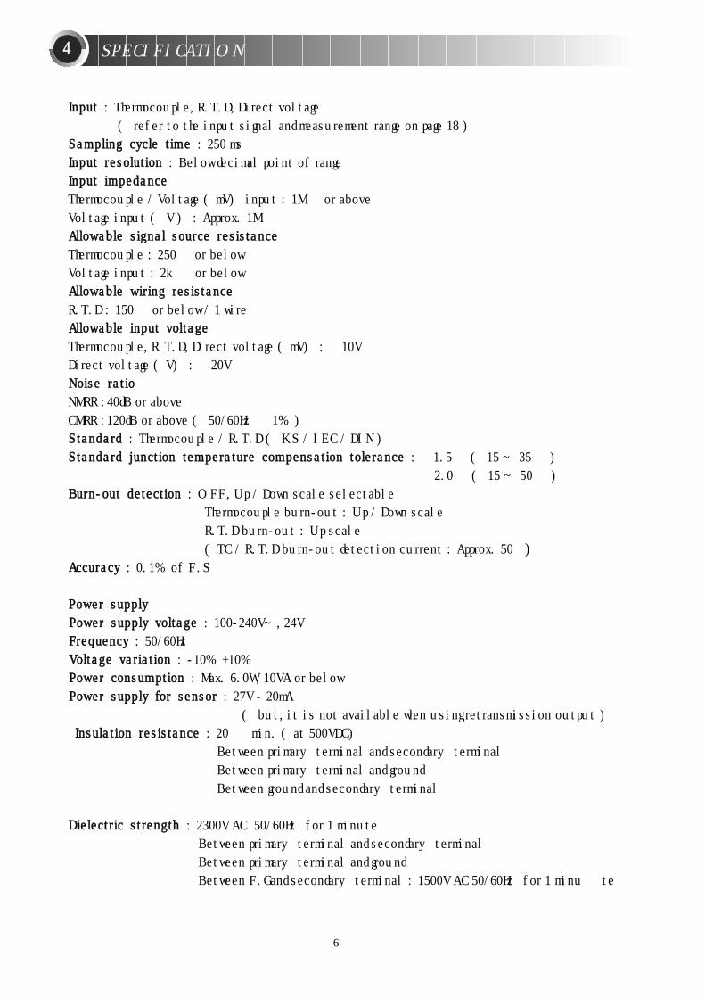
IInnppuutt ttyyppee sseelleeccttiioonn
After power ON and when PV is indicating, press key for 3 sec to be displayed at PVand 3 at SV. (If it is not indicated 3, set again in the level setting mode)① Control group is indicated when press key once more. At the time, ⑫ input group is indicatedwhen press key and then “Input type and range selection" is shown at SV when press . At thistime the input and range is selected by or key.
DDiissppllaayy uunniitt (/)After selecting input type and range, press key to select display unit. Press key to choose or and press key when finishing selection.
MMaaxxiimmuumm aanndd MMiinniimmuumm rraannggeeAfter selecting display unit, press key to set Maximum and Minimum range using or key. Press key once more to finish.
DDeecciimmaall ppooiinnttParameter is not indicated in T.C and R.T.D input, but when selecting voltage input (code 30,32,33),“DDeecciimmaall ppooiinntt”mode is indicated. (set 1 : 0.0, set 2 : 0.00, set 3 : 0.000)
MMaaxxiimmuumm aanndd MMiinniimmuumm oonn ssccaalleeIt is the same function as Maximum and Minimum range setting when R.T.D or thermocouple input.This mode is indicated when voltage input ( 30, 32, 33 )
PPVV ffiilltteerrWhen PV value becomes unstable due to effects of noise, the filter helps suppress the unstablestatus. (Range: OFF or 1~120sec. Initial value: OFF)
PPVV bbiiaassUse this function to adjust PV value in cases where it is necessary for PV value to agree withanother recorder or indicator, or when the sensor cannot be mounted in correct location.(Range : -100.0~100.0% of SPAN, lnitial value : 0.0%) Setting a value using or key and press key to finish.
17
INPUT GROUP SETTING
When setting, ““IInnppuutt ttyyppee sseelleeccttiioonn nnuummbbeerr””must be selected in the input type selection mode and also““OOuuttppuutt ttyyppee sseelleeccttiioonn nnuummbbeerr””must be selected in the output type selection mode before moving toother mode. If not, data of other group will be changed to prior value.
1111
CCAAUUTTIIOONN

K
K
J
E
T
R
B
S
L
N
U
W
PlatinelⅡ
JPt100
Pt100
1.000~5.000V
-10.00~20.00mV
0.0~100.0mV
1.000~5.000V
-10.00~20.00mV
0.0~100.0mV
±0.10% of F.S±1digit
±0.15% of F.S
±1digit
±0.10% of F.S ±1digit
±0.20% of F.S ±1digit
±0.10% of F.S
±1digit
±0.10% of F.S±1digit
±0.10% of F.S±1digit
-300~2500
0~2300
-300~2300
-300~1800
-300~750
32~3100
32~3300
32~3100
-300~1300
-300~2400
-300~750
32~4200
32~2500
-199.9~999.9
-300~1180
F.S is maximum value of
each RANGE
1 0~400 : ±5% of
F.S±1digit
2 0 and below :
±0.2% of
F.S±1digit
3 -150.0~150.0 :
±0.2% of
F.S±1digit
Input code Input signal Range () Range () Accuracy Remarks
18
1
2
3
4
5
6
7
8
9
10
11
12
13
20
21
30
32
33
SelectionNO.1
1370
-200
1
100.0
0.0
OFF
EUS(0.0%)
UP
Signal Name Description Condition Initial value
Input group
Input signal selection
Measurement range unit
High limit
Low limit
Decimal point
Maximum on scale(on voltage input)Minimum on scale(on voltage input)
PV filter
PV bias
Burn-out
Input type and mode selection
Refer to input signal and range
/
Refer to input signal and range
( Notice : FR-H > FR-L )
Thermocouple or R.T.D : decimal point ofinstrument / DC Voltage : 0~3
-1999~9999
Notice : SL-H 〉 SL-L
Deimal point : according to DP-P
OFF/1~120sec
EUS (-100.0~100.0%)
OFF / UP / DOWN
Always
Thermocouple or R.T.D
Always
Always
On voltage input (mV,V)
On voltage input (mV,V)
Always
Always
Always
2
2
2
2
2
2
1
2
2
3
3
-200~1370
-199.9~999.9
-199.9~999.9
-199.9~999.9
-199.9~400.0
0~1700
0~1800
0~1700
-199.9~900.0
-200~1300
-199.9~400.0
0~2300
0~1390
-199.9~500.0
-199.9~640.0
INPUT SIGNAL AND MEASUREMENT RANGE
※Current input : The current input (DC4~20mA) is available with input code 30.You must use the resistance 250Ω(0.5W / 0.1%) on input terminals.

Output group
Output signal
Output operation
Cycle time
Cycle time of cooling output
Hysteresis of univesal type
Hysterecis of Heating/Cooling type
Output volume when inputdisconnection Output 1 (Out1)
Output volume when inputdisconnection Output 2 (Out2)
Maximum value
Minimum value
Output code(O T)
0
1
2
3
OUT1 OUT2
Always
Output code 1~3
Relay / SSR
Output code 4~12
ON/OFF Control
Heating/Cooling
Always
Heating / Cooling
PID Control
PID Control
(3 / 12)
REV
30 sec
30 sec
EUS(0.5%)0.5%
0.0%
0.0%
100.0%
0.0 %100.0%
OUTPUT GROUP SETTING
Signal Name Description Condition Initial value
Output type and mode selection
Refor to type of control output
REV: Reverse DIR: Direct action
1~1000 sec
1~1000 sec
EUS(0.0~100.0%)
0.0~10.0%
Universal : -5.0~105.0%Heating / Cooling : 0.0~105.0%
0.0~105.0%
Universal : OL-L + 1Digit~ 105.0%Heating / Cooling : 0.0~ 105.0%Universal : -0.5%~ OL-H-1DigitHeating / Cooling : 0.0~ 105.0%
Relay
Relay ON / OFF
Relay
PX9-0PX7-0PX3-0PX2-0
SSR / Current
SSR
Current
Type of control output ( Universal type )
This process controller is divided into 2 types: UNIVERSAL TYPE AND HEATING / COOLING TYPE.Output is selectable from Relay, SSR, and Current (4~20mA DC).Output type range (output code) is ~③ for universal type and ④~⑫ for Heating /Cooling type.Sometimes retransmission output and alarm output are not available according to control output (EX. When you choose output code (OT) 2, it is current output of Universal type. In this case,retransmission output and alarm output are available. But, In Heating / Cooling control type with SSRon Heating side and Relay output on Cooling side (output code ⑩), the retransmission output isavalable but alarm output 3 is not available.
ModelSSR / Current / Retransmission
Retransmission
Retransmission
Retransmission
Retransmission
19
1122
When setting, ““IInnppuutt ttyyppee sseelleeccttiioonn nnuummbbeerr””must be selected in the input type selection modeand also ““OOuuttppuutt ttyyppee sseelleeccttiioonn nnuummbbeerr””must be selected in the output type selection modebefore moving to other mode.If not, data of other group will be changed to prior value.
CCAAUUTTIIOONN

Set value group is indicated with selecting Local mode or Remote mode in GROUP CONTROL(Not Program mode). “ Select number of SV ”is after setting 3 type of set value in Local mode, selecteach set value from external contact input to operate. After selecting number of set value, press key,you could set set-value of SV1, SV2, and SV3.
1
EU(0.0%)
EU(0.0%)
EU(0.0%)
Relay(AL3)
Relay(AL3)
Relay(AL3)
SSR
Current
Retransmission
SSR
Current
Retransmission
SSR
Current
Relay
Relay
Relay
SSR
SSR
SSR
Current
Current
Current
Retransmission
Retransmission
Retransmission
Type of control output (Heating / Cooling type )
Model
4
5
6
7
8
9
10
11
12
Heating (OUT1) Cooling (OUT2)Output code
(O T) SSR / CurrentRelay SSR / Current /Retransmission Relay
20
Signal Name Description Condition Initial value
Set value group
Select number of set value
Set SV 1
Set SV 2
Set SV 3
Set value setting
1~3
EU(0.0~100.0%)
EU(0.0~100.0%)
EU(0.0~100.0%)
REM / LOCA
REM / LOCA
REM / LOCA
REM / LOCA
PX9-0
PX7-0
PX3-0
PX2-0
SET VALUE GROUP SETTING1133
EU : Value at an engineering unit in compliance with the range of an instrument.

Signal Name Description Condition Initial value
PROGRAM GROUP SETTING (RAMP / SOAK)
OFF: Reset / ON: Start
H.MIN: 99H 59min.M.SEC: 99M 59sec.
OFF / EUS(1~10%)
OFF(0.00)~99.59 (Refer to time unit)
0.0~100.0% of input range
SSV:Start set value / PV1:Process value PV2:time prior set value
EU(0.0~100.0%)
OFF / 0.00~9959
0.0~100.0%
OFF / 0.00~99.59
Reset / Repeat / Local / Hold
OFF
M.SEC
OFF
OFF(0.00)
EU(0.0%)
SSV
EU(0.0%)
OFF
EU(0.0%)
OFF
RST
PROG
PROG
PROG
PROG
PROG
PROG
PROG
PROG
PROG
PROG
PROG
Program group
start / Reset selection
Time unit
Wait Zone
Wait Time
Start set value
Standard of start
Set SV1
Time setting of fist step
Set SV10
Time setting of tenth step
Condition select after finishingprogram control
If Program mode is selected in Group Control, the controller becomes a programmable (ramp/ soak) controller with 1 pattern of 10 step. After setting time and set value, this controller controls automatically.
A pattern is a series of steps. Each step consists of a SV and time setting. An Increasing or decreasing SV is set for time period, and each time setting is in hours/ minutes or minutes/ seconds.
After wiring, check and power ON. PV and SV will be indicated.At this time, press key 3sec. to enter (display) in PV and then press key once more to get Group Control (SV is off).
At this condition, press key to get control mode(Mod) in PV and select program (PROG) in SV using or .
Press key once more to set program and then press key 3 times to get group control (G: CTL) in PV (SV is off). And then press key to be indicated program group as below.
21
TIM
Set value
TIM(min) MIN(sec.)
1144
SStteepp NNOO..
Pattern

STD
OFF
Signal Name Description Condition Initial value
AUTO TUNING
Auto tuning group
Auto tuning type
Auto tuning start
Indicates Auto tuning
STD / LOW
OFF / 1~3 / AUTO
ABS
ABS
This controller has two types of auto-tuning as STD (Standard type) andLOW(Low PV type). Low PV type is the value 10% lower than the set value. Use this type whereovershoot is to be suppressed.
※※AAuuttoo--ttuunniinngg:: The Auto-tuning function automatically measures, computes and set the optimum P.I.D and ARW contants. The Auto-tuning function can be activated at any time during the process after power ON; while temperature is rising or when control has stabilized.Auto tuning is not operated when selecting ““OOFFFF””in selection mode of auto tuning start.
22
1155

Signal Name Description Condition Initial value
P.I.D group
Anti Reset Wind-Up
P.I.D group selection
n. Proportional band(P)
n. Integal time ( I )
n. Derivative time (D)
n. Manual reset
n. Proportional band of cooling side (P)
n. Integral time of cooling side ( I )
n. Derivative time of cooling side (D)
n. Hysteresis
n. Zone point
Set P.I.D mode
Auto / 50.0~200.0%
0 / 1~3
0.1 (H/C TYPE:0.0)~999.9%
OFF / 1~600 sec.
OFF / 1~6000sec.
-5.0~105.0%
0.0 (ON/OFF control) / 0.1~999.9
OFF / 1~6000 sec.
OFF / 1~6000 sec.
-100.0~50.0%
EU (0) < 1.RP < 2.RP < EU (100.0%)
P.I.D control
Always
P.I.D group
Always
Always
Integral time: OFF
Heating•Cooling type
Heating•Cooling type
Heating•Cooling type
Heating•Cooling type
ZONE = ON
Auto
0
5.0%
240 sec.
60 sec.
50.0%
5.0%
240 sec.
60 sec.
3.0%
EU(100.0%)
Time
Zone 3
Set point of Zone 2 (2,RP)
Set point of Zone 1 (1,RP)
Maximum Range (Eu:100%)
Minimum (Eu: 0%)
Zone 2
Zone 1
When checking P.I.D. values or setting SV in manual mode,this can be done in P.I.D. Group.Press key to get Anti Reset Wind value by auto ormanual and then press once more to be indicated P.I.Dmode which is selectable 3 types of P.I.D group (0~3).Example, “0”is no P.I.D mode and after Auto tuning“1”usingor and pressing , it is available to change P.I.Dvalue in zone “1”(“2”and “3”are same as “1”) When integral time is 0, manual reset mode is indicated andthen you could set reset value to remove off set (range: -5%~105.0% of proportional band). You could set 3 zones byselecting zone mode ON.
※ In diagram, “n”is available to set 1~3 and proportional band of cooling side, integral time of cooling side, hysteresis are indicated in Heating / Cooling type.
23
P.I.D GROUP1166

Signal Name Description Condition Initial value
ALARM GROUP SETTING
1
2
1
EUS(0.5%)
EU(100.0%)
EU(0.0%)
EU(100.0%)
Always
Always
Always
Set alarm mode
OFF / 1~22 Refer to “AAllaarrmm ttyyppee aanndd ccooddee”
EUS ( 0.0~100.0% )
PV alarm, Deviation alarmEU ( -100.0~100.0% )
Alarm group
Type of Alarm 1
Type of Alarm 2
Type of Alarm 3
Dead band of Alarm 1
Dead band of Alarm 2
Dead band of Alarm 3
Set value of Alarm 1
Set value of Alarm 2
Set value of Alarm 3
There are 3 alarm outputs available per conrtoller. In Alarm Group, setting are made for mode, deadband, and value of each alarm. Refer to the next page for the 19 different types of alarm functions.
: ① In Heating·Cooling type of PX7, is not indicated when selecting 10,11,12: ② In PX7, is not indicated because of no third alarm output.
In Heating·Cooling type of PX3, PX2, PX9, is not indicated when selecting 10, 11, 12
24
1177
※Reference : Display lamp will be OFF when output ON in inverted type.
HHoolldd ffuunnccttiioonn
Without hold function, Low limit alarm will be ON when increasing temperature. (Picture 1)
SV
(low limit alarm)
Power ON
Alarm output ON OFF ON OFF
PV
(Picture 1)
SV
(low limit
Power ON
OFF OFF ON OFF
PV
(Picture 2)
HHoolldd ffuunnccttiioonn :: NNoonnee HHoolldd ffuunnccttiioonn
Alarm output

( : Set point , : Minus Alarm set point , : Alarm set point )
Code NO.
1
2
3
4
5
6
7
8
9
10
11
12
13
14
15
16
17
18
19
20
21
22
High absolute value
Low absolute value
High deviation value
Low deviation value
High deviation value (inverted)
Low deviation value (inverted)
High·Low deviation value
High·Low band
High absolute (inverted)
Low absolute (inverted)
High absolute with hold function
Low absolute with hold function
High deviation with hold function
Low deviation with hold function
High deviation with hold function(inverted)
Low deviation with hold function(inverted)
High·Low deviation with holdfunction
High·Low band with hold function
High absolute value with holdfunction (inverted)
Low absolute value with holdfunction (inverted)
Heater break alarm 1 ( HBA 1 )
Heater break alarm 2 ( HBA 2 )
Function
ALARM TYPE AND CODE
25
Alarm type
Hysteresis
((NNoottiiccee)) :: Display lamp will be ON when output OFF in inverted type.

Set retransmission mode
PV / SV / Output volume (MV)Power for sensor (SPS)
Thermocouple / R.T.D : FR -H ~ FR- LDC voltage : SL -H ~ SL-Lbut, RET. H > RET.L
Retransmission group
Retransmission typeor Power for sensorHight limit ofretransmissionLow limit ofretransmission
Signal Name Description Condition Initial value
Signal Name Description Condition Initial value
RETRANSMISSION GROUP
Optional
PV / SV
※Reference : Retransmission group will be indicated when selecting retransmisson in output group. If selecting code 4,5,7 or 8 in output group, retransmisson will not be indicated.
26
PV
COMMUNICATION
Communication group
RS485/RS422 ProtocolCommunication rate(B.P.S)
Parity check
Stop bit
Data length
Address
Response time
Set communication mode
PC.LINK(Set value:0) / PC.LINK SUM (Set value:1)
600(SV:0) / 1200(SV:1) / 2400(SV:2) 4800(SV:3) / 9600(SV:4)
NONE(SV:0)/EVEN(SV:1)/ODD(SV:2)
1bit (SV:1) / 2bit (SV:2)
7bit (SV:7) / 8bit (SV:8) (Except PC LINK :8)
1~99 , maximum 31 devices
0~10. response time = (handling time + response time) X 10ms
Optional
0
4
1
1
8
1
0
PX series are equipped with 4 wire /2 wire half-duplex the RS485 / RS422 communication interfaces.Using the interfaces, communications are available with maximum 31 devices.
1188
1199
※Reference

Remote group
High limit voltage of remote input
Low limit voltage of remote input
High limit on scale
Low limit on scale
PV Filter
PV Bias
27
Signal Name Description Condition Initial value
Heater break alarm group
Current setting mode of HBA 1
Current setting mode of HBA 2
Hysteresis setting mode HBA 1
Hysteresis setting mode HBA 2
Current measurement value of HBA 1
Current measurement value of HBA 2
OFF / 1~50A
OFF / 1~50A
EUS (0.0~100.0%)
EUS (0.0~100.0%)
Only display (0~50A)
Only display (0~50A)
OFF
OFF
EUS(0.5%)
EUS(0.5%)
Set HBA mode
5.000
1.000
1
2
OFF
EUS(0.0%)
Signal Name Description Condition Initial value
REMOTE INPUT GROUP
If selecting REMOTE in Control group, set value will be set by remote set.In remote condition, SV is changeable by front keys, but the controller is controlled by external setvalue. Do not change set value by remote in auto tuning.
Set remote mode
1,000~5,000Vbut, R. INH > R. INL
Thermocouple : FR-H ~ FR-L DC voltage : SL-H ~ SL-LDecimal point is set by DP-P.
OFF / 1~120
EUS (-100.0~100.0%)
HEATER BREAK ALARM GROUP
Heater break alarm group consist of output dead band and current detection display mode and detects 2spots (to be ordered seperately: current transformer model CTL-6-S. measurement range : 1~50A).
2200
2211
1 : Thermocouple, R.T.D input ( FR-H ), DC voltage ( SL-H )2 : Thermocouple, R.T.D input ( FR-L ), DC voltage ( SL-L )EUS : Range at an engineering unit in compliance with the span of an instrument.
: It is not indicated in PX7. (There is no HBA function in PX2, PX3)
Optional
Optional

#40-11, 2-ga, Mullae dong Youngdeungpo-ku, Seoul, KoreaTEL:(82-2) 679-4697 FAX:(82-2) 2633-3332
http://www.hanyoungelec.co.kr E-mail: [email protected]

![PTT Multicasting Scheme [호환 모드] · 2 New PTT Group Add by Mouse right button click 3PTTGrouppg Name Setting 4 PTT Group Number Setting 5 PTT Server Setting 6 PTT Group Session](https://img.pdfslide.net/doc/110x75/5f727989ade5745a8a06acb0/ptt-multicasting-scheme-eeoe-2-new-ptt-group-add-by-mouse-right-button.jpg)