Embed Size (px)
Citation preview
Pyramid-Based Texture Analysis/Synthesis
David J. Heeger�
Stanford UniversityJames R. Bergeny
SRI David Sarnoff Research Center
Abstract
This paper describes a method for synthesizing images that matchthe texture appearanceof a given digitized sample. This synthesis iscompletely automatic and requires only the “target” texture as input.It allows generation of as much texture as desired so that any objectcan be covered. It can be used to produce solid textures for creat-ing textured 3-d objects without the distortions inherent in texturemapping. It can also be used to synthesize texture mixtures, imagesthat look a bit like each of several digitized samples. The approachis based on a model of human texture perception, and has potentialto be a practically useful tool for graphics applications.
1 Introduction
Computer renderings of objects with surface texture are more inter-esting and realistic than those without texture. Texture mapping [15]is a technique for adding the appearance of surface detail by wrap-ping or projecting a digitized texture image onto a surface. Digitizedtextures can be obtained from a variety of sources, e.g., croppedfrom a photoCD image, but the resulting texture chip may not havethe desired size or shape. To cover a large object you may need torepeat the texture; this can lead to unacceptableartifacts either in theform of visible seams, visible repetition, or both.
Texture mapping suffers from an additional fundamental prob-lem: often there is no natural map from the (planar) texture imageto the geometry/topology of the surface, so the texture may be dis-torted unnaturally when mapped. There are some partial solutionsto this distortion problem [15] but there is no universal solution formapping an image onto an arbitrarily shaped surface.
An alternative to texture mapping is to create (paint) textures byhand directly onto the 3-d surface model [14], but this process isboth very labor intensive and requires considerable artistic skill.
Another alternative is to use computer-synthesized textures sothat as much texture can be generated as needed. Furthermore, someof the synthesis techniques produce textures that tile seamlessly.
Using synthetic textures, the distortion problem has been solvedin two different ways. First, some techniques work by synthesizingtexture directly on the object surface (e.g., [31]). The second solu-tion is to use solid textures [19, 23, 24]. A solid texture is a 3-d ar-ray of color values. A point on the surface of an object is colored bythe value of the solid texture at the corresponding 3-d point. Solidtexturing can be a very natural solution to the distortion problem:
�Department of Psychology, Stanford University, Stanford, CA [email protected] http://white.stanford.edu
ySRI David Sarnoff Research Center, Princeton, NJ [email protected]
there is no distortion because there is no mapping. However, exist-ing techniques for synthesizing solid textures can be quite cumber-some. One must learn how to tweak the parameters or proceduresof the texture synthesizer to get a desired effect.
This paper presents a technique for synthesizing an image (orsolid texture) that matches the appearanceof a given texture sample.The key advantage of this technique is that it works entirely from theexample texture, requiring no additional information or adjustment.The technique starts with a digitized image and analyzes it to com-pute a number of texture parameter values. Those parameter val-ues are then used to synthesize a new image (of any size) that looks(in its color and texture properties) like the original. The analysisphase is inherently two-dimensional since the input digitized imagesare 2-d. The synthesis phase, however, may be either two- or three-dimensional. For the 3-d case, the output is a solid texture such thatplanar slices through the solid look like the original scanned image.In either case, the (2-d or 3-d) texture is synthesized so that it tilesseamlessly.
2 Texture Models
Textures have often been classified into two categories, determinis-tic textures and stochastic textures. A deterministic texture is char-acterized by a set of primitives and a placement rule (e.g., a tilefloor). A stochastic texture, on the other hand, does not have easilyidentifiable primitives (e.g., granite, bark, sand). Many real-worldtextures have some mixture of these two characteristics (e.g. wovenfabric, woodgrain, plowed fields).
Much of the previous work on texture analysis and synthesiscan be classified according to what type of texture model wasused. Some of the successful texture models include reaction-diffusion [31, 34], frequency domain [17], fractal [9, 18], and sta-tistical/random field [1, 6, 8, 10, 12, 13, 21, 26] models. Some (e.g.,[10]) have used hybrid models that include a deterministic (or pe-riodic) component and a stochastic component. In spite of all thiswork, scanned images and hand-drawn textures are still the princi-ple source of texture maps in computer graphics.
This paper focuses on the synthesis of stochastic textures. Ourapproach is motivated by research on human texture perception.Current theories of texture discrimination are based on the fact thattwo textures are often difficult to discriminate when they producea similar distribution of responses in a bank of (orientation andspatial-frequency selective) linear filters [2, 3, 7, 16, 20, 32]. Themethod described here, therefore, synthesizes textures by match-ing distributions (or histograms) of filter outputs. This approach de-pends on the principle (not entirely correct as we shall see) that allof the spatial information characterizing a texture image can be cap-tured in the first order statistics of an appropriately chosen set of lin-ear filter outputs. Nevertheless, this model (though incomplete) cap-tures an interesting set of texture properties.
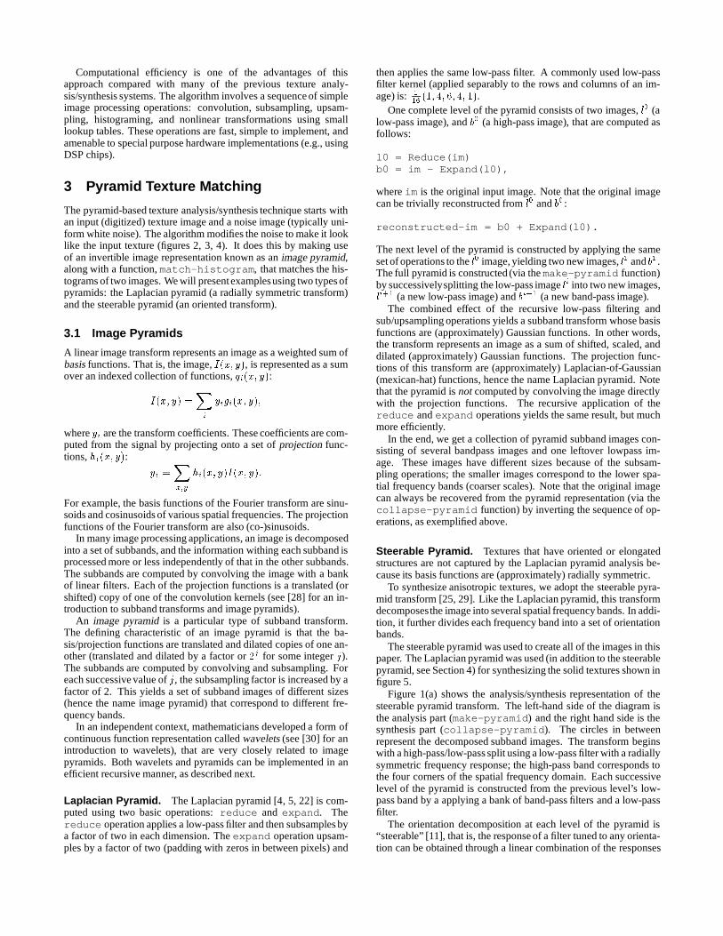
Computational efficiency is one of the advantages of thisapproach compared with many of the previous texture analy-sis/synthesis systems. The algorithm involves a sequence of simpleimage processing operations: convolution, subsampling, upsam-pling, histograming, and nonlinear transformations using smalllookup tables. These operations are fast, simple to implement, andamenable to special purpose hardware implementations (e.g., usingDSP chips).
3 Pyramid Texture Matching
The pyramid-based texture analysis/synthesis technique starts withan input (digitized) texture image and a noise image (typically uni-form white noise). The algorithm modifies the noise to make it looklike the input texture (figures 2, 3, 4). It does this by making useof an invertible image representation known as an image pyramid,along with a function, match-histogram, that matches the his-tograms of two images. We will present examplesusing two types ofpyramids: the Laplacian pyramid (a radially symmetric transform)and the steerable pyramid (an oriented transform).
3.1 Image Pyramids
A linear image transform represents an image as a weighted sum ofbasis functions. That is, the image, I(x;y), is represented as a sumover an indexed collection of functions, gi(x; y):
I(x; y) =X
i
yigi(x; y);
where yi are the transform coefficients. These coefficients are com-puted from the signal by projecting onto a set of projection func-tions, hi(x;y):
yi =X
x;y
hi(x; y)I(x; y):
For example, the basis functions of the Fourier transform are sinu-soids and cosinusoids of various spatial frequencies. The projectionfunctions of the Fourier transform are also (co-)sinusoids.
In many image processing applications, an image is decomposedinto a set of subbands, and the information withing each subband isprocessed more or less independently of that in the other subbands.The subbands are computed by convolving the image with a bankof linear filters. Each of the projection functions is a translated (orshifted) copy of one of the convolution kernels (see [28] for an in-troduction to subband transforms and image pyramids).
An image pyramid is a particular type of subband transform.The defining characteristic of an image pyramid is that the ba-sis/projection functions are translated and dilated copies of one an-other (translated and dilated by a factor or 2j for some integer j).The subbands are computed by convolving and subsampling. Foreach successive value of j, the subsampling factor is increased by afactor of 2. This yields a set of subband images of different sizes(hence the name image pyramid) that correspond to different fre-quency bands.
In an independent context, mathematicians developed a form ofcontinuous function representation called wavelets (see [30] for anintroduction to wavelets), that are very closely related to imagepyramids. Both wavelets and pyramids can be implemented in anefficient recursive manner, as described next.
Laplacian Pyramid. The Laplacian pyramid [4, 5, 22] is com-puted using two basic operations: reduce and expand. Thereduce operation applies a low-pass filter and then subsamples bya factor of two in each dimension. The expand operation upsam-ples by a factor of two (padding with zeros in between pixels) and
then applies the same low-pass filter. A commonly used low-passfilter kernel (applied separably to the rows and columns of an im-age) is: 1
16(1; 4; 6; 4; 1).
One complete level of the pyramid consists of two images, l0 (alow-pass image), and b0 (a high-pass image), that are computed asfollows:
l0 = Reduce(im)b0 = im - Expand(l0),
where im is the original input image. Note that the original imagecan be trivially reconstructed from l0 and b0:
reconstructed-im = b0 + Expand(l0).
The next level of the pyramid is constructed by applying the sameset of operations to the l0 image, yielding two new images, l1 and b1 .The full pyramid is constructed (via the make-pyramid function)by successivelysplitting the low-pass image li into two new images,li+1 (a new low-pass image) and bi+1 (a new band-pass image).
The combined effect of the recursive low-pass filtering andsub/upsampling operations yields a subband transform whose basisfunctions are (approximately) Gaussian functions. In other words,the transform represents an image as a sum of shifted, scaled, anddilated (approximately) Gaussian functions. The projection func-tions of this transform are (approximately) Laplacian-of-Gaussian(mexican-hat) functions, hence the name Laplacian pyramid. Notethat the pyramid is not computed by convolving the image directlywith the projection functions. The recursive application of thereduce and expand operations yields the same result, but muchmore efficiently.
In the end, we get a collection of pyramid subband images con-sisting of several bandpass images and one leftover lowpass im-age. These images have different sizes because of the subsam-pling operations; the smaller images correspond to the lower spa-tial frequency bands (coarser scales). Note that the original imagecan always be recovered from the pyramid representation (via thecollapse-pyramid function) by inverting the sequence of op-erations, as exemplified above.
Steerable Pyramid. Textures that have oriented or elongatedstructures are not captured by the Laplacian pyramid analysis be-cause its basis functions are (approximately) radially symmetric.
To synthesize anisotropic textures, we adopt the steerable pyra-mid transform [25, 29]. Like the Laplacian pyramid, this transformdecomposesthe image into several spatial frequency bands. In addi-tion, it further divides each frequency band into a set of orientationbands.
The steerable pyramid was used to create all of the images in thispaper. The Laplacian pyramid was used (in addition to the steerablepyramid, see Section 4) for synthesizing the solid textures shown infigure 5.
Figure 1(a) shows the analysis/synthesis representation of thesteerable pyramid transform. The left-hand side of the diagram isthe analysis part (make-pyramid) and the right hand side is thesynthesis part (collapse-pyramid). The circles in betweenrepresent the decomposed subband images. The transform beginswith a high-pass/low-pass split using a low-pass filter with a radiallysymmetric frequency response; the high-pass band corresponds tothe four corners of the spatial frequency domain. Each successivelevel of the pyramid is constructed from the previous level’s low-pass band by a applying a bank of band-pass filters and a low-passfilter.
The orientation decomposition at each level of the pyramid is“steerable” [11], that is, the response of a filter tuned to any orienta-tion can be obtained through a linear combination of the responses
H0
L 0 B0
B1
B2
B3
H0
L 0B0
B1
B2
B3
L 1 2 L 12
a
cb
d
etc.
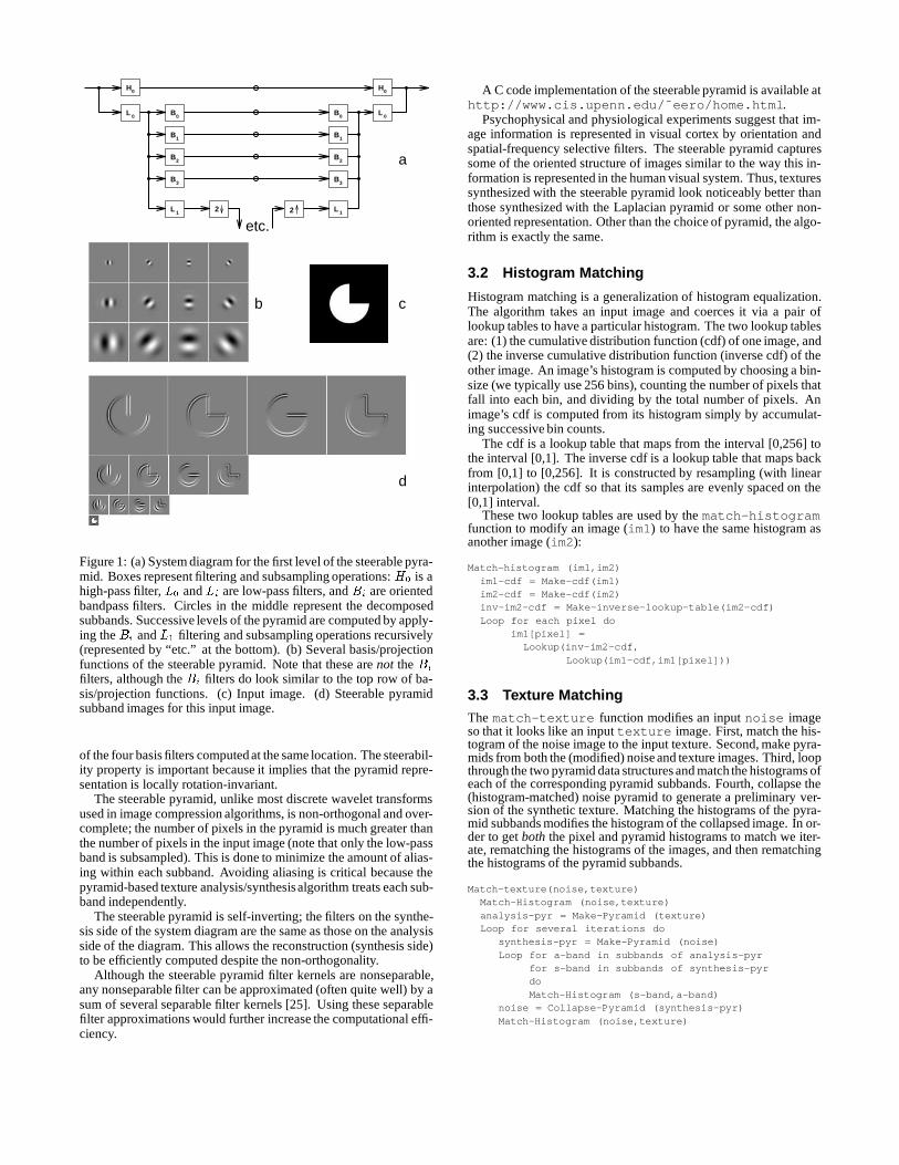
Figure 1: (a) System diagram for the first level of the steerable pyra-mid. Boxes represent filtering and subsampling operations: H0 is ahigh-pass filter, L0 and Li are low-pass filters, and Bi are orientedbandpass filters. Circles in the middle represent the decomposedsubbands. Successive levels of the pyramid are computed by apply-ing the Bi and L1 filtering and subsampling operations recursively(represented by “etc.” at the bottom). (b) Several basis/projectionfunctions of the steerable pyramid. Note that these are not the Bi
filters, although the Bi filters do look similar to the top row of ba-sis/projection functions. (c) Input image. (d) Steerable pyramidsubband images for this input image.
of the four basis filters computed at the same location. The steerabil-ity property is important because it implies that the pyramid repre-sentation is locally rotation-invariant.
The steerable pyramid, unlike most discrete wavelet transformsused in image compression algorithms, is non-orthogonal and over-complete; the number of pixels in the pyramid is much greater thanthe number of pixels in the input image (note that only the low-passband is subsampled). This is done to minimize the amount of alias-ing within each subband. Avoiding aliasing is critical because thepyramid-based texture analysis/synthesisalgorithm treats each sub-band independently.
The steerable pyramid is self-inverting; the filters on the synthe-sis side of the system diagram are the same as those on the analysisside of the diagram. This allows the reconstruction (synthesis side)to be efficiently computed despite the non-orthogonality.
Although the steerable pyramid filter kernels are nonseparable,any nonseparable filter can be approximated (often quite well) by asum of several separable filter kernels [25]. Using these separablefilter approximations would further increase the computational effi-ciency.
A C code implementation of the steerable pyramid is available athttp://www.cis.upenn.edu/˜eero/home.html.
Psychophysical and physiological experiments suggest that im-age information is represented in visual cortex by orientation andspatial-frequency selective filters. The steerable pyramid capturessome of the oriented structure of images similar to the way this in-formation is represented in the human visual system. Thus, texturessynthesized with the steerable pyramid look noticeably better thanthose synthesized with the Laplacian pyramid or some other non-oriented representation. Other than the choice of pyramid, the algo-rithm is exactly the same.
3.2 Histogram Matching
Histogram matching is a generalization of histogram equalization.The algorithm takes an input image and coerces it via a pair oflookup tables to have a particular histogram. The two lookup tablesare: (1) the cumulative distribution function (cdf) of one image, and(2) the inverse cumulative distribution function (inverse cdf) of theother image. An image’s histogram is computed by choosing a bin-size (we typically use 256 bins), counting the number of pixels thatfall into each bin, and dividing by the total number of pixels. Animage’s cdf is computed from its histogram simply by accumulat-ing successive bin counts.
The cdf is a lookup table that maps from the interval [0,256] tothe interval [0,1]. The inverse cdf is a lookup table that maps backfrom [0,1] to [0,256]. It is constructed by resampling (with linearinterpolation) the cdf so that its samples are evenly spaced on the[0,1] interval.
These two lookup tables are used by the match-histogramfunction to modify an image (im1) to have the same histogram asanother image (im2):
Match-histogram (im1,im2)im1-cdf = Make-cdf(im1)im2-cdf = Make-cdf(im2)inv-im2-cdf = Make-inverse-lookup-table(im2-cdf)Loop for each pixel do
im1[pixel] =Lookup(inv-im2-cdf,
Lookup(im1-cdf,im1[pixel]))
3.3 Texture Matching
The match-texture function modifies an input noise imageso that it looks like an input texture image. First, match the his-togram of the noise image to the input texture. Second, make pyra-mids from both the (modified) noise and texture images. Third, loopthrough the two pyramid data structures and match the histograms ofeach of the corresponding pyramid subbands. Fourth, collapse the(histogram-matched) noise pyramid to generate a preliminary ver-sion of the synthetic texture. Matching the histograms of the pyra-mid subbands modifies the histogram of the collapsed image. In or-der to get both the pixel and pyramid histograms to match we iter-ate, rematching the histograms of the images, and then rematchingthe histograms of the pyramid subbands.
Match-texture(noise,texture)Match-Histogram (noise,texture)analysis-pyr = Make-Pyramid (texture)Loop for several iterations do
synthesis-pyr = Make-Pyramid (noise)Loop for a-band in subbands of analysis-pyr
for s-band in subbands of synthesis-pyrdoMatch-Histogram (s-band,a-band)
noise = Collapse-Pyramid (synthesis-pyr)Match-Histogram (noise,texture)
Whenever an iterative scheme of this sort is used there is a con-cern about convergence. In the current case we have not formallyinvestigated the convergence properties of the iteration, but our ex-perience is that it always converges. However, stopping the algo-rithm after several (5 or so) iterations is critical. As is the case withnearly all discrete filters, there are tradeoffs in the design of thesteerable pyramid filters (e.g., filter size versus reconstruction ac-curacy). Since the filters are not perfect, iterating too many timesintroduces artifacts due to reconstruction error.
The core of the algorithm is histogram matching which is a spa-tially local operation. How does this spatially local operation repro-duce the spatial characteristics of textures? The primary reason isthat histogram matching is done on a representation that has intrin-sic spatial structure. A local modification of a value in one of thepyramid subbands produces a spatially correlated change in the re-constructed image. In other words, matching the pointwise statisticsof the pyramid representation does match some of the spatial statis-tics of the reconstructed image. Clearly, only spatial relationshipsthat are represented by the pyramid basis functions can be capturedin this way so the choice of basis functions is critical. As mentionedabove, the steerable pyramid basis functions are a reasonably goodmodel of the human visual system’s image representation.
If we had a complete model of human texture perception thenwe could presumably synthesize perfect texture matches. By anal-ogy, our understanding of the wavelength encoding of light in theretina allows us to match the color appearance of (nearly) any colorimage with only three colored lights (e.g., using an RGB monitor).Lights can be distinguished only if their spectral compositions dif-fer in such a way as to produce distinct responses in the three pho-toreceptor classes. Likewise, textures can be distinguished only iftheir spatial structures differ in such a way as to produce distinct re-sponses in the human visual system.
3.4 Edge Handling
Proper edge handling in the convolution operations is important.For the synthesis pyramid, use circular convolution. In otherwords, for an image I(x;y) of size NxN, define: I(x;y) �
I(xmodN; ymodN). Given that the synthesis starts with a ran-dom noise image, circular convolution guarantees that the resultingsynthetic texture will tile seamlessly.
For the analysis pyramid, on the other hand, circular convolutionwould typically result in spuriously large filter responses at the im-age borders. This would, in turn, introduce artifacts in the synthe-sized texture. A reasonable border handler for the analysis pyramidis to pad the image with a reflected copy of itself. Reflecting at theborder usually avoids spurious responses (except for obliquely ori-ented textures).
3.5 Color
The RGB components of a typical texture image are not indepen-dent of one another. Simply applying the algorithm to R, G, and Bseparately would yield color artifacts in the synthesized texture.
Instead, color textures are analyzedby first transforming the RGBvalues into a different color space. The basic algorithm is appliedto each transformed color band independently producing three syn-thetic textures. These three textures are then transformed back intothe RGB color space giving the final synthetic color texture.
The color-space transformation must be chosen to decorrelate thecolor bands of the input texture image. This transformation is com-puted from the input image in two steps. The first step is to sub-tract the mean color from each pixel. That is, subtract the averageof the red values from the red value at each pixel, and likewise forthe green and blue bands. The resulting color values can be plottedas points in a three-dimensional color space. The resulting 3-d cloud
of points is typically elongated in some direction, but the elongateddirection is typically not aligned with the axes of the color space.
The second step in the decorrelating color transform rotates thecloud so that its principle axes align with the axes of the new colorspace. The transform can be expressed as a matrix multiplication,y =Mx, where x is the RGB color (after subtracting the mean) ofa particular pixel, y is the transformed color, andM is a 3x3 matrix.
The decorrelating transformM is computed from the covariancematrixC using the singular-value-decomposition (SVD). LetD bea 3xN matrix whose columns are the (mean-subtracted) RGB val-ues of each pixel. The covariance matrix is: C = DDt, whereDt means the transpose of D. The SVD algorithm algorithm de-composes the covariance matrix into the product of three compo-nents,C = US2Ut. Here,U is an orthonormal matrix and S2 isa diagonal matrix. These matrices (C,U and S2) are each 3x3, sothe SVD can be computed quickly. The decorrelating transform is:M = S�1Ut, where S is a diagonal matrix obtained by taking thesquare-root of the elements of S2.
After applying this color transform, the covariance of the trans-formed color values is the identity matrix. Note that the transformedcolor values are: MD = S�1UtUSVt = Vt. It follows that thecovariance of the transformed color values is: VtV = I.
The color transform is inverted after synthesizing the three tex-ture images in the transformed color space. First, multiply the syn-thetic texture’s color values at each pixel by M�1. This producesthree new images (color bands) transformed back into the (meansubtracted) RGB color space. Then, add the corresponding meanvalues (the means that were subtracted from the original input tex-ture) to each of these color bands.
4 Solid Textures
Pyramid-based texture analysis/synthesis can also be used to makeisotropic 3-d solid textures. We start with an input image and ablock of 3-d noise. The algorithm coerces the noise so that any slicethrough the block looks like the input image.
The solid texture synthesis algorithm is identical to that describedabove, except for the choice of pyramid: use a 2-d Laplacian pyra-mid for analysis and a 3-d Laplacian pyramid for synthesis. Asusual, match the histograms of the corresponding subbands. Notethat since the Laplacian pyramid is constructed using separable con-volutions, it extends trivially to three-dimensions.
We have obtained better looking results using a combination ofLaplacian and steerable pyramids. On the analysis side, construct a2-d Laplacian pyramid and a 2-d steerable pyramid. On the synthe-sis side, construct a 3-d Laplacian pyramid and construct steerablepyramids from all two-dimensional (x-y, x-z, and y-z) slices of thesolid. Match the histograms of the 3-d (synthesis) Laplacian pyra-mid to the corresponding histograms of the 2-d (analysis) Lapla-cian pyramid. Match the histograms of each of the many synthe-sis steerable pyramids to the corresponding histograms of the analy-sis steerable pyramid. Collapsing the synthesis pyramids gives foursolids (one from the 3-d Laplacian pyramid and one from each setof steerable pyramids) that are averaged together. Some examplesare shown in figure 5.
5 Texture Mixtures
Figure 6 shows some texture mixtures that were synthesized bychoosing the color palette (decorrelating color transform) from oneimage and the pattern (pyramid subband statistics) from a secondimage.
One can imagine a number of other ways to mix/combine texturesto synthesize an image that looks a bit like each of the inputs: ap-ply match-texture to a second image rather than noise, com-bine the high frequencies of one texture with the low frequencies ofanother, combine two or more textures by averaging their pyramidhistograms, etc.
6 Limitations and Extensions
The approach presented in this paper, like other texture synthesistechniques, has its limitations. The analysis captures some but notall of the perceptually relevant structure of natural textures. Hence,this approach should be considered one of many tools for texturingobjects in computer graphics.
It is critical that the input image be a homogeneous texture. Fig-ure 7 shows two input textures (cropped from different areas of thesame photoCD image) and two corresponding synthetic textures.When the input is inhomogeneous (due to an intensity gradient, con-trast gradient, perspective distortion, etc.) then the synthesized tex-ture has a blotchy appearance.
The approach also fails on quasi-periodic textures and on ran-dom mosaic textures (figure 8). Although the results look inter-esting, they do not particularly resemble the inputs. We have hadsome success synthesizing quasi-periodic textures using a hybridscheme (e.g., like [10]) that combines a periodic texture model withthe pyramid decomposition. Methods that are specifically designedto capture long range statistical correlation [26] have also been suc-cessful with textures of this type. The issue with random mosaictextures is mainly one of scale. If the repeated micro-patterns aresmall enough, then the pyramid analysis/synthesis scheme workswell (e.g., see the ivy example in figure 3).
Figure 9 shows more examples of failures. There are two as-pects of these images that the pyramid texture model misses. First,these textures are locally oriented but the dominant orientation isdifferent in different parts of the image. In a sense, they are inho-mogeneous with respect to orientation. Second, they contain ex-tended, fine structure (correlations of high frequency content overlarge distances). The pyramid scheme captures correlations of lowfrequency content over large distances, but it captures correlationsof high frequency content only over very short distances.
There is no general way to construct an anisotropic solid tex-ture from a 2-d sample. However, there are several options includ-ing: (1) constructing a solid texture as the outer product of a 2-d anisotropic color texture image and a 1-d (monochrome) signal;(2) composing (adding, multiplying, etc.) several solid textures asPeachy [23] did; (3) starting with an isotropic solid, and introducinganisotropy procedurally, like Perlin’s marble [24] and Lewis’ wood-grain [19]; (4) starting with an isotropic solid, and using a paint pro-gram to introduce anisotropic “touch-ups”.
Image pyramids and multi-scale image representations of onesort or another are the most often used data structures for antialiasedtexture mapping (e.g., Renderman, Silicon Graphics Iris GL, Gen-eral Electric and E&S realtime flight simulators, and reference [33]).Pyramid-based texture synthesis, therefore, can be naturally inte-grated into an antialiased texture mapping system.
Finally, it may be possible to write an interactive tool for texturesynthesis, with a slider for each parameter in the pyramid represen-tation. In our current implementation, each subband histogram isencoded with 256 bins. However the subband histograms of many“natural” images have a characteristic shape [27], suggesting that avery small number of parameters may be sufficient.
7 Conclusion
This paper presents a technique for created a two- or three-dimensional (solid) texture array that looks like a digitized textureimage. The advantage of this approach is its simplicity; you do nothave to be an artist and you do not have to understand a complextexture synthesis model/procedure. You just crop a textured regionfrom a digitized image and run a program to produce as much of thattexture as you want.
Acknowledgements: The teapot images were rendered usingRayshade. Many of the source texture images were cropped fromphotoCDs distributed by Pixar and Corel. Special thanks to EeroSimoncelli for designing the filters for the steerable pyramid, toPatrick Teo for writing a solid texturing extension to Rayshade,to Alex Sherstinsky for suggesting the solid texturing application,to Marc Levoy for his help and encouragement, and to CharlieChubb and Mike Landy for stimulating discussions. Supported byan NIMH grant (MH50228), an NSF grant (IRI9320017), and an Al-fred P. Sloan Research Fellowship to DJH.
References
[1] BENNIS, C., AND GAGALOWICZ, A. 2-D Macroscopic Tex-ture Synthesis. Computer GraphicsForum 8 (1989), 291–300.
[2] BERGEN, J. R. Theories of Visual Texture Perception. InSpatial Vision, D. Regan, Ed. CRC Press, 1991, pp. 114–133.
[3] BERGEN, J. R., AND ADELSON, E. H. Early Vision and Tex-ture Perception. Nature 333 (1988), 363–367.
[4] BURT, P. Fast Filter Transforms for Image Processing. Com-puter Graphics and Image Processing 16 (1981), 20–51.
[5] BURT, P. J., AND ADELSON, E. H. A Multiresolution Splinewith Application to Image Mosaics. ACM Transactions onGraphics 2 (1983), 217–236.
[6] CHELLAPPA, R., AND KASHYAP, R. L. Texture SynthesisUsing 2-D Noncausal Autoregressive Models. IEEE Transac-tions on Acoustics, Speech, and Signal Processing 33 (1985),194–203.
[7] CHUBB, C., AND LANDY, M. S. Orthogonal DistributionAnalysis: A New Approach to the Study of Texture Percep-tion. In Computational Models of Visual Processing, M. S.Landy and J. A. Movshon, Eds. MIT Press, Cambridge, MA,1991, pp. 291–301.
[8] CROSS, G. C., AND JAIN, A. K. Markov Random Field Tex-ture Models. IEEE Transactions on Pattern Analysis and Ma-chine Intelligence 5 (1983), 25–39.
[9] FOURNIER, A., FUSSEL, D., AND CARPENTER, L. Com-puter Rendering of Stochastic Models. Communications of theACM 25 (1982), 371–384.
[10] FRANCOS, J. M., MEIRI, A. Z., AND PORAT, B. A Uni-fied Texture Model Based on a 2D Wold-Like Decomposition.IEEE Transactions on Signal Processing 41 (1993), 2665–2678.
[11] FREEMAN, W. T., AND ADELSON, E. H. The Design andUse of Steerable Filters. IEEE Transactions on Pattern Anal-ysis and Machine Intelligence 13 (1991), 891–906.
[12] GAGALOWICZ, A. Texture Modelling Applications. The Vi-sual Computer 3 (1987), 186–200.
[13] GAGALOWICZ, A., AND MA, S. D. Sequential Synthesis ofNatural Textures. Computer Vision, Graphics, and Image Pro-cessing 30 (1985), 289–315.
[14] HANRAHAN, P., AND HAEBERLI, P. Direct WYSIWYGPainting and Texturing of 3D Shapes. Proceedings of SIG-GRAPH 90. In Computer Graphics (1990), vol. 24, ACMSIGGRAPH, pp. 215–223.
[15] HECKBERT, P. S. Survey of Texture Mapping. IEEE Com-puter Graphics and Applications 6 (1986), 56–67.
[16] LANDY, M. S., AND BERGEN, J. R. Texture Segregation andOrientation Gradient. Vision Research 31 (1991), 679–691.
[17] LEWIS, J. P. Texture Synthesis for Digital Painting. Pro-ceedings of SIGGRAPH 84. In Computer Graphics (1984),vol. 18, ACM SIGGRAPH, pp. 245–252.
[18] LEWIS, J. P. Generalized Stochastic Subdivision. ACMTransactions on Graphics 6 (1987), 167–190.
[19] LEWIS, J. P. Algorithms for Solid Noise Synthesis. Pro-ceedings of SIGGRAPH 89. In Computer Graphics (1989),vol. 23, ACM SIGGRAPH, pp. 263–270.
[20] MALIK, J., AND PERONA, P. Preattentive Texture Discrimi-nation with Early Vision Mechanisms. Journal of the OpticalSociety of America A 7 (1990), 923–931.
[21] MALZBENDER, T., AND SPACH, S. A Context SensitiveTexture Nib. In Communicating with Virtual Worlds, N. M.Thalmann and D. Thalmann, Eds. Springer-Verlag, New York,1993, pp. 151–163.
[22] OGDEN, J. M., ADELSON, E. H., BERGEN, J. R., AND
BURT, P. J. Pyramid-Based Computer Graphics. RCA En-gineer 30 (1985), 4–15.
[23] PEACHY, D. R. Solid Texturing of Complex Surfaces. Pro-ceedings of SIGGRAPH 85. In Computer Graphics (1985),vol. 19, ACM SIGGRAPH, pp. 279–286.
[24] PERLIN, K. An Image Synthesizer. Proceedings of SIG-GRAPH 85. In Computer Graphics (1985), vol. 19, ACMSIGGRAPH, pp. 287–296.
[25] PERONA, P. Deformable Kernels for Early Vision. IEEETransactions on Pattern Analysis and Machine Intelligence(1995). To appear May 1995.
[26] POPAT, K., AND PICARD, R. W. Novel Cluster-Based Prob-ability Model for Texture Synthesis, Classification, and Com-pression. In Proceedingsof SPIE Visual Communications andImage Processing (1993), pp. 756–768.
[27] RUDERMAN, D. L., AND BIALEK, W. Statistics of NaturalImages: Scaling in the Woods. Physical Review Letters 73(1994), 814–817.
[28] SIMONCELLI, E. P., AND ADELSON, E. H. Subband Trans-forms. In Subband Image Coding, J. W. Woods, Ed. KluwerAcademic Publishers, Norwell, MA, 1990.
[29] SIMONCELLI, E. P., FREEMAN, W. T., ADELSON, E. H.,AND HEEGER, D. J. Shiftable Multi-Scale Transforms.IEEE Transactions on Information Theory, Special Issue onWavelets 38 (1992), 587–607.
[30] STRANG, G. Wavelets and Dilation Equations: A Brief Intro-duction. SIAM Review 31 (1989), 614–627.
[31] TURK, G. Generating Textures on Arbitrary Surfaces UsingReaction-Diffusion. Proceedings of SIGGRAPH 91. In Com-puter Graphics (1991), vol. 25, ACM SIGGRAPH, pp. 289–298.
[32] TURNER, M. R. Texture Discrimination by Gabor Functions.Biological Cybernetics 55 (1986), 71–82.
[33] WILLIAMS, L. Pyramidal Parametrics. Proceedings of SIG-GRAPH 83. In Computer Graphics (1983), vol. 17, ACMSIGGRAPH, pp. 1–11.
[34] WITKIN, A., AND KASS, M. Reaction-Diffusion Tex-tures. Proceedings of SIGGRAPH 91. In Computer Graphics(1991), vol. 25, ACM SIGGRAPH, pp. 299–308.
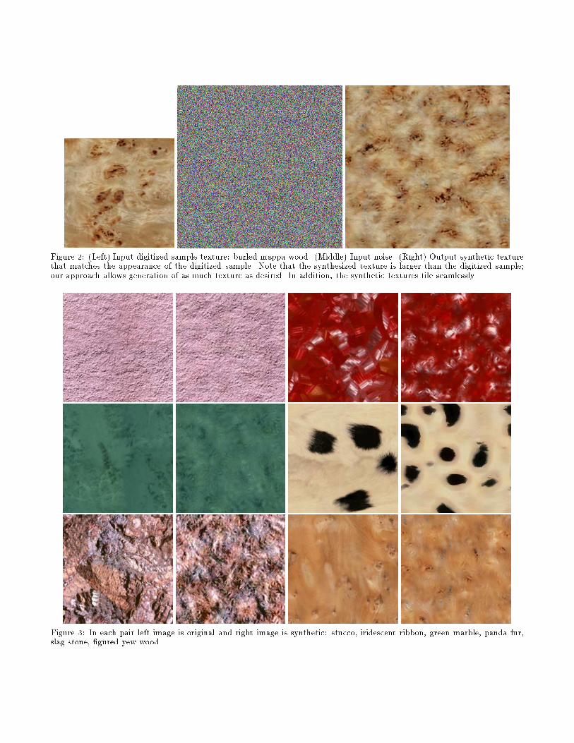
Figure 2: (Left) Input digitized sample texture: burled mappa wood. (Middle) Input noise. (Right) Output synthetic texturethat matches the appearance of the digitized sample. Note that the synthesized texture is larger than the digitized sample;our approach allows generation of as much texture as desired. In addition, the synthetic textures tile seamlessly.
Figure 3: In each pair left image is original and right image is synthetic: stucco, iridescent ribbon, green marble, panda fur,slag stone, �gured yew wood.
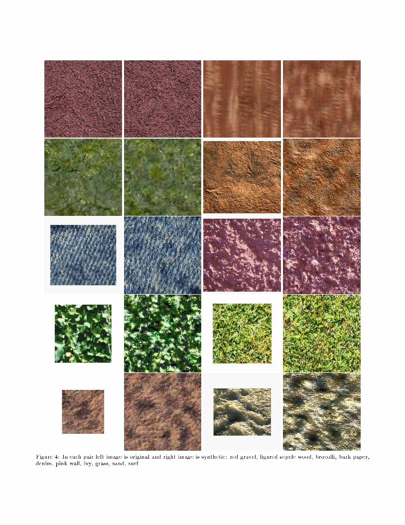
Figure 4: In each pair left image is original and right image is synthetic: red gravel, �gured sepele wood, brocolli, bark paper,denim, pink wall, ivy, grass, sand, surf.
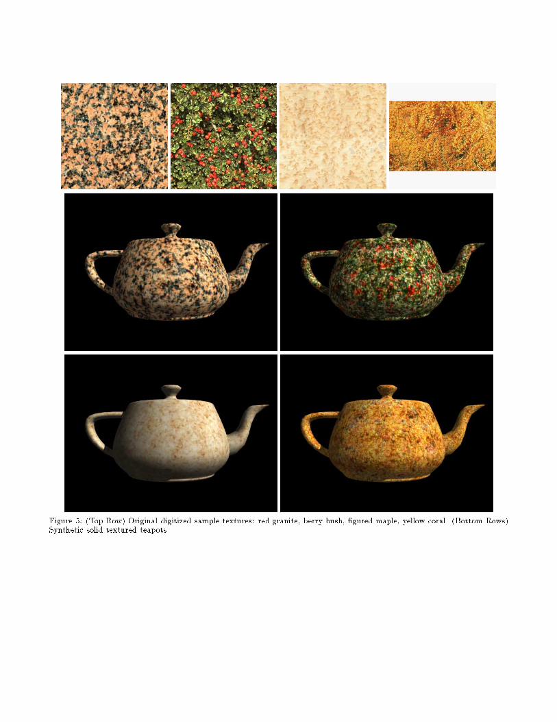
Figure 5: (Top Row) Original digitized sample textures: red granite, berry bush, �gured maple, yellow coral. (Bottom Rows)Synthetic solid textured teapots.
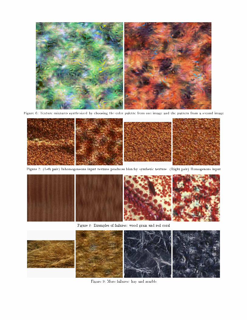
Figure 6: Texture mixtures synthesized by choosing the color palette from one image and the pattern from a second image.
Figure 7: (Left pair) Inhomogoneous input texture produces blotchy synthetic texture. (Right pair) Homogenous input.
Figure 8: Examples of failures: wood grain and red coral.
Figure 9: More failures: hay and marble.