Embed Size (px)
Citation preview
Pyrogen Technologies (AUST) Pty. Ltd. P.O. Box 694 Hurstville 1481 18 Barry Avenue Mortdale NSW 2223 Australia
Tel: 61 2 9586 3200 Fax: 61 2 9586 32 11 E-mail: [email protected] Website: www.pyrogen.com
CNC Manual: Pyr-02 Issued: November 2013 Revision No.: 11/13
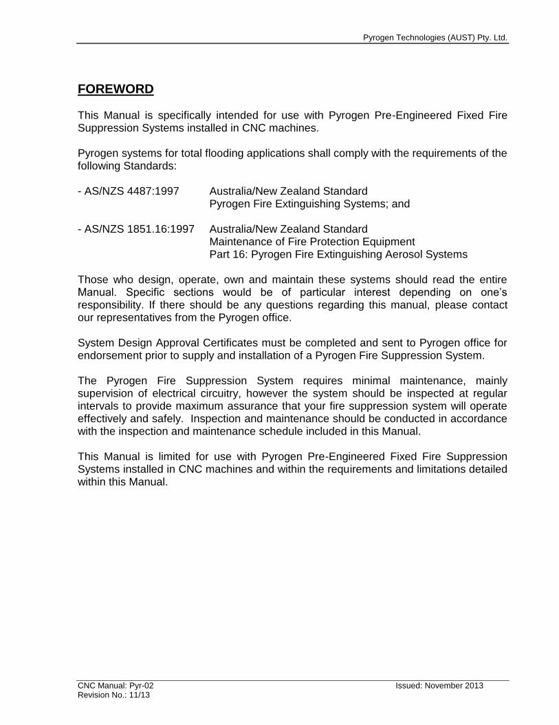
PRE-ENGINEERED FIXED AEROSOL FIRE SUPPRESSION SYSTEM
IN CNC MACHINES
DESIGN, OPERATION & MAINTENANCE
MANUAL
This manual is issued by Pyrogen Technologies (AUST) Pty. Ltd. and is for use by trained and authorised personnel only. Unauthorised copying of this manual and its contents and use by
unauthorised personnel is strictly forbidden and may lead to legal action against those who do so. This document is accurate at time of issue and Pyrogen reserves the right to make changes to its
content from time to time.
Pyrogen Technologies (AUST) Pty. Ltd.
CNC Manual: Pyr-02 Issued: November 2013 Revision No.: 11/13
FOREWORD This Manual is specifically intended for use with Pyrogen Pre-Engineered Fixed Fire Suppression Systems installed in CNC machines. Pyrogen systems for total flooding applications shall comply with the requirements of the following Standards: - AS/NZS 4487:1997 Australia/New Zealand Standard Pyrogen Fire Extinguishing Systems; and - AS/NZS 1851.16:1997 Australia/New Zealand Standard Maintenance of Fire Protection Equipment Part 16: Pyrogen Fire Extinguishing Aerosol Systems Those who design, operate, own and maintain these systems should read the entire Manual. Specific sections would be of particular interest depending on one’s responsibility. If there should be any questions regarding this manual, please contact our representatives from the Pyrogen office. System Design Approval Certificates must be completed and sent to Pyrogen office for endorsement prior to supply and installation of a Pyrogen Fire Suppression System. The Pyrogen Fire Suppression System requires minimal maintenance, mainly supervision of electrical circuitry, however the system should be inspected at regular intervals to provide maximum assurance that your fire suppression system will operate effectively and safely. Inspection and maintenance should be conducted in accordance with the inspection and maintenance schedule included in this Manual. This Manual is limited for use with Pyrogen Pre-Engineered Fixed Fire Suppression Systems installed in CNC machines and within the requirements and limitations detailed within this Manual.
Pyrogen Technologies (AUST) Pty. Ltd.
CNC Manual: Pyr-02 Issued: November 2013 Revision No.: 11/13
TABLE OF CONTENTS
Section 1. Terminology…………………………………………………………………...5 of 47 Section 2. Product Description 2.1 What is Pyrogen?…………………………………………………………………….7 of 47 2.2 Pyrogen Chemical Identity………………………………………………………………...8 2.3 Pyrogen Extinguishing Action …………………………………………………………....10 2.4 Pyrogen Application & Limitation………………………………………………….…….12 2.5 Pyrogen Safety Data…………….………………………………………………….…….14 2.6 Pyrogen Environmental Characteristics.………………………………………….…….16 2.7 Pyrogen Technical Characteristics…..………………………………………………….17 2.8 Pyrogen Discharge………………………………………………………………………..18 Section 3. System Supply 3.1 List of Components………………………………………………………………….19 of 47 3.2 Pyrogen Aerosol Module………………………………………………………………...19 3.3 Controller (Fire Panel)…………………………………………………………………….19 3.4 Break Glass………………………………………………………………………………...23 3.5 Thermal Probe Detector…………………………………………………………………..23 3.6 Strobe/Sounder…………………………………………………………………………….24 3.7 Elbow Mounting Unit…………………………………………………………………..…..24 Section 4. System Design 4.1 General……………………………………………………………………………….26 of 47 4.2 Pyrogen EXA-MA-5 Aerosol Module……….………..…………………………………...26 4.3 Enclosure Requirements….………………………………………………………………27 4.4 Pyrogen Service Life………………………………………………………………………29 Section 5. System Operation 5.1 Operation mode……………………………………………………………………..30 of 47 5.2 Operation in Fire Situation………………………………………………………………..30 Section 6. System Installation 6.1 Design & Acceptance Documentation…………………………………………...31 of 47 6.2 System Integrity…………………………………………………………………………...31 6.3 Prior to Installation………………………………………………………………………..32 6.4 Installation Location………………………………………………………………………32 6.5 Mounting…………………………………………………………………. ……………….32 6.6 Electric Wiring……………………………………………………………………………..33
Pyrogen Technologies (AUST) Pty. Ltd.
CNC Manual: Pyr-02 Issued: November 2013 Revision No.: 11/13
Section 7. System Marking 7.1 Installation & Expiry Date Label…………………………………………………………36 of 47 7.2 Warning & Instruction Sign……………………………………………………………………..36 Section 8. System Commissioning………………………………………………………….37 of 47 Section 9. System Maintenance…………………………………………………………….37 of 47 Appendix a - Approval Documentation Form 1- System Design Approval Certificate………………………………………………38 of 47 Form 2- Commissioning & Acceptance Testing………………………………………………….41 Form 3- Notice of Completion.……………………………………………………………………..45 Form 4 - Maintenance Check List………………………………………………………….……...46 Form 5 - Annual Maintenance Certificate…………………………………………………. …….47
Pyrogen Technologies (AUST) Pty Ltd _____________________________________________________________________________________________
CNC Manual: Pyr-02 Issued: November 2013 Revision No.: 11/13
SECTION 1: TERMINOLOGY The following definitions apply to this document: Actuating mechanism: automatic or manual activation leading to the physical discharge of the extinguishant. Aerosol: an extinguishant consisting of finely divided solid particles and gaseous matter, these being combustion products of a solid aerosol-forming compound. Aerosol-forming compound: a mixture of a solid combustible component, a solid potassium salt-based oxidant and solid technical admixtures producing fire-extinguishing aerosol upon activation; contained inside a Pyrogen module. Aerosol module: same as Pyrogen module Aggressive environment: where environmental variables such as temperature and/or vibration undergo cycling at or close to the extreme limits of the Pyrogen module. Corrosive atmosphere may also be a factor. Automatic: performing a function without the necessity of human intervention. Automatic/Manual Switch: a device that can be operated before a person enters a space protected by Pyrogen fire suppression system to prevent automatic release of fire extinguishing aerosol. Normal detection sequence is unaffected. Class A fires: fire involving solid materials, usually of organic nature. Can be further categorised into surface burning fires and deep-seated fires. Deep-seated fires smoulder and may combust slowly beneath the surface of the hazard. Class B fires: fires involving liquids or liquefiable solids. Class C fires: fires involving gases. Class E fires: electrically energised fuels. Class F fires: fats and cooking oils. Control device: a device to control the sequence of events leading to the release of the extinguishant. Cooling element: a heat absorbing material contained inside a Pyrogen module. Design application density (g/m
3): the mass of Pyrogen solid aerosol-forming compound
per m3 of enclosure volume required to extinguish a specific type of fire, including a
safety factor.
Pyrogen Technologies (AUST) Pty Ltd _____________________________________________________________________________________________
CNC Manual: Pyr-02 Issued: November 2013 Revision No.: 11/13
Design quantity (g): the mass of Pyrogen solid aerosol-forming compound necessary to extinguish a fire in a particular risk, including a safety factor. Extinguishant: aerosol produced from Pyrogen module. Module: same as Pyrogen module. Holding time: the period during which the extinguishant is required to maintain a minimum effective concentration. Hot Work: grinding, welding, thermal or oxygen cutting or heating and other related heat-producing or spark-producing operations. Location drawing: a plan of the risk clearly indicating the as-installed location of all Pyrogen modules, controls and maintenance isolate switch. Manual: requiring human intervention to accomplish a function. Monitoring: the supervision of the operating integrity of an electrical control feature of a system. Normally occupied area: an area where, under normal circumstances, humans are present. Normally unoccupied area: an area that is not occupied by humans under normal circumstances but may be entered occasionally for brief periods. Operating device: any component involved between actuation and release. Pyrogen module: a device capable of generating the Pyrogen aerosol extinguishant when activated either electrically or thermally. Consists of an electrical and/or thermal activation device, an aerosol-forming compound and a cooling element enclosed within a corrosion-resistant casing incorporating an end-plate nozzle. Release: the action leading to the physical discharge or emission of the extinguishant into the enclosure. Smouldering: slow combustion of material without visible light and generally evidenced by smoke and an increase in temperature. System isolate switch: see Automatic/Manual switch. Total flooding system: a fixed fire suppression system, which distributes the extinguishing medium throughout the protected enclosure.
Pyrogen Technologies (AUST) Pty Ltd _____________________________________________________________________________________________
CNC Manual: Pyr-02 Issued: November 2013 Revision No.: 11/13
SECTION 2: PRODUCT DESCRIPTION 2.1 What is Pyrogen? Pyrogen is a self-generated Aerosol Fire Extinguishing Agent, and is one of the most efficient Halon Alternative products currently available. The principle of extinguishing action employed by Pyrogen is unique - a special solid chemical, Pyrogen aerosol-forming compound, when electrically or thermally activated, undergoes a combustion reaction to produce micron sized dry chemical particles and gases. Dry chemical particles - mainly potassium carbonates, and gases - mainly carbon dioxide, nitrogen and water vapour, mix together into an uniform aerosol, which represents an actual extinguishing medium. Before being released into a protected area, the aerosol propels itself through a Pyrogen cooling element, which absorbs heat, thus ensuring a low temperature discharge and uniform distribution of the aerosol within the area. As aerosol is self-generated it requires no pressure cylinders and does not need to be stored. The aerosol generating chemical reaction provides a sufficient driving force for a rapid discharge and efficient distribution of the aerosol. No piping is required. The solid aerosol-forming compound together with the solid cooling element and activation devices is contained in a small non-pressurised canister with one or two end-plate delivery nozzles. The canisters are called EXA modules and vary in size depending on the mass of the solid aerosol-forming compound contained in the module. EXA canisters are very compact and normally placed inside the protected enclosure. Operation of the module is either electrical automatic, electrical manual or thermal automatic. Pyrogen aerosol is a whitish gas-like medium that is close in density to air. Small particle size ensures three-dimensional distribution qualities and long suspension times. Pyrogen aerosol is non-conductive and non-corrosive. As Pyrogen aerosol stays in suspension for extended periods, it can be removed from the protected area by any airflow. Solid fraction of the aerosol that has settled can easily be brushed, blown or washed away.
Pyrogen Technologies (AUST) Pty Ltd _____________________________________________________________________________________________
CNC Manual: Pyr-02 Issued: November 2013 Revision No.: 11/13
2.2 Pyrogen Chemical Identity The secret to Pyrogen’s power is in two unique formulations contained in Pyrogen canister - the solid aerosol-forming compound and the solid cooling element. The solid aerosol element is a thermoplastic mixture consisting of an oxidiser, a combustible binder and technological additives. The oxidiser is a solid potassium nitrate (KNO3(s)), the combustible binder is an organic polymer (CnHmNpOq(s)) and technological additives include an activator of the oxidiser’s decomposition, chemical and mechanical stabilisers and some other ingredients. When activated the solid aerosol element undergoes a combustion reaction, which can schematically be represented as follows: KNO3 (s) + CnHmNpOq (s) = KHCO3 (s) + K2CO3 (s) + CO2 (g) + N2(g) + H2O (g) Combustion products mainly consist of potassium carbonates (KHCO3 , K2CO3), carbon dioxide gas (CO2 (g)), nitrogen gas ( N2 (g) ) and water vapour (H2O(g)) and represent the actual extinguishing agent. As the reaction temperatures are high, potassium carbonates are formed in the gas phase, but as the vapour cools, the potassium carbonates condense to a liquid and then a solid. As solid potassium carbonates are produced by condensation, the particle size is very small - approximately from 1 to 10 microns. Micron sized solid particles mix with the gaseous carbon dioxide, nitrogen and water into a uniform homogeneous gas-like phase - an aerosol. Thus, Pyrogen extinguishing aerosol is a suspension of the micron sized solid particles, mainly potassium carbonates, in the gas mix of carbon dioxide, nitrogen and water vapour. Being a combustion product of the aerosol-forming compound, Pyrogen aerosol is hot upon formation. Although, Pyrogen aerosol is the most effective in terms of the actual fire extinguishment when in its hottest state, the negative impacts of very high temperatures are obvious. That is where a second unique formulation - the cooling element - comes into action. When the hot Pyrogen aerosol passes through the cooling element, the latest absorbs heat. Application of the Pyrogen cooling element provides uniform distribution of the aerosol within the area, which certainly contributes to the reliability and safety of the extinguishment. Moreover, additional amounts of inert gases are formed due to a thermal decomposition of the cooling element, which contribute to the effectiveness of the extinguishment.
Pyrogen Technologies (AUST) Pty Ltd _____________________________________________________________________________________________
CNC Manual: Pyr-02 Issued: November 2013 Revision No.: 11/13
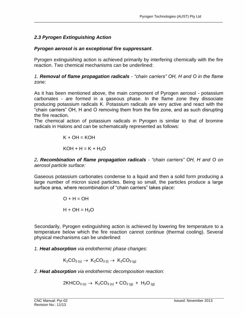
2.3 Pyrogen Extinguishing Action Pyrogen aerosol is an exceptional fire suppressant. Pyrogen extinguishing action is achieved primarily by interfering chemically with the fire reaction. Two chemical mechanisms can be underlined: 1. Removal of flame propagation radicals - “chain carriers” OH, H and O in the flame zone: As it has been mentioned above, the main component of Pyrogen aerosol - potassium carbonates - are formed in a gaseous phase. In the flame zone they dissociate producing potassium radicals K. Potassium radicals are very active and react with the “chain carriers” OH, H and O removing them from the fire zone, and as such disrupting the fire reaction. The chemical action of potassium radicals in Pyrogen is similar to that of bromine radicals in Halons and can be schematically represented as follows: K + OH = KOH KOH + H = K + H2O 2. Recombination of flame propagation radicals - “chain carriers” OH, H and O on aerosol particle surface: Gaseous potassium carbonates condense to a liquid and then a solid form producing a large number of micron sized particles. Being so small, the particles produce a large surface area, where recombination of “chain carriers” takes place: O + H = OH H + OH = H2O Secondarily, Pyrogen extinguishing action is achieved by lowering fire temperature to a temperature below which the fire reaction cannot continue (thermal cooling). Several physical mechanisms can be underlined: 1. Heat absorption via endothermic phase changes:
K2CO3 (s) K2CO3 (l) K2CO3 (g) 2. Heat absorption via endothermic decomposition reaction:
2KHCO3 (s) K2CO3 (s) + CO2 (g) + H2O (g)
Pyrogen Technologies (AUST) Pty Ltd _____________________________________________________________________________________________
CNC Manual: Pyr-02 Issued: November 2013 Revision No.: 11/13
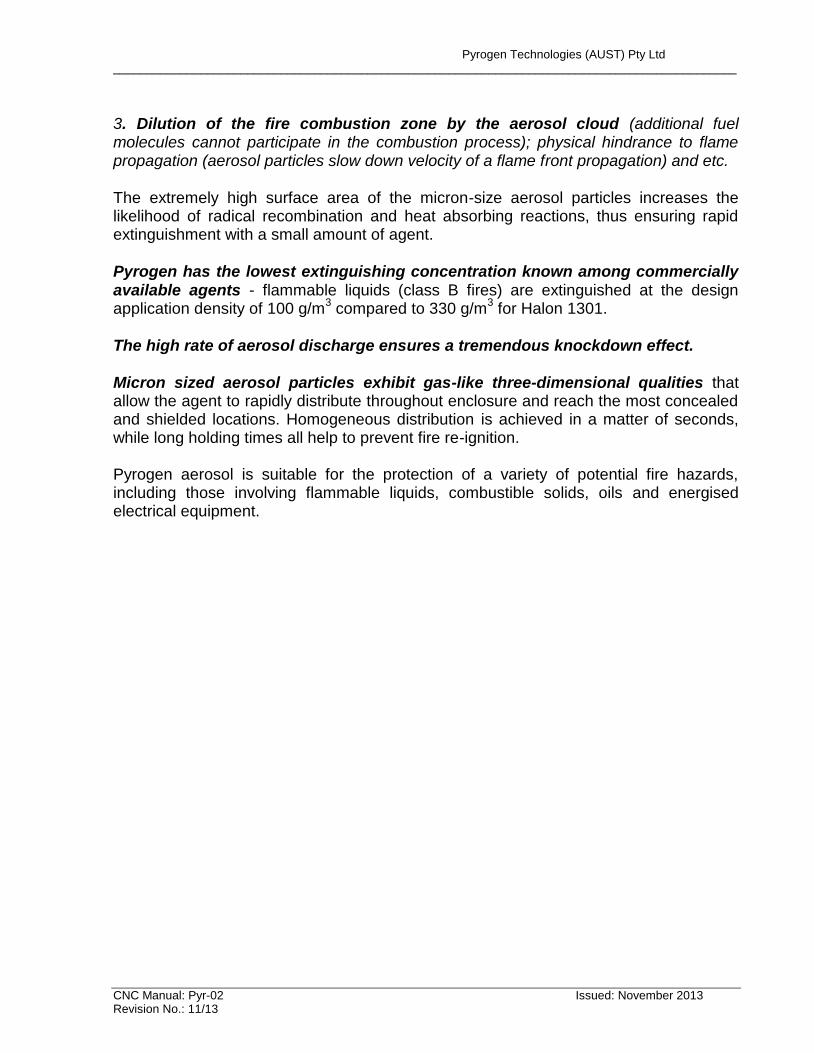
3. Dilution of the fire combustion zone by the aerosol cloud (additional fuel molecules cannot participate in the combustion process); physical hindrance to flame propagation (aerosol particles slow down velocity of a flame front propagation) and etc. The extremely high surface area of the micron-size aerosol particles increases the likelihood of radical recombination and heat absorbing reactions, thus ensuring rapid extinguishment with a small amount of agent. Pyrogen has the lowest extinguishing concentration known among commercially available agents - flammable liquids (class B fires) are extinguished at the design application density of 100 g/m
3 compared to 330 g/m
3 for Halon 1301.
The high rate of aerosol discharge ensures a tremendous knockdown effect. Micron sized aerosol particles exhibit gas-like three-dimensional qualities that allow the agent to rapidly distribute throughout enclosure and reach the most concealed and shielded locations. Homogeneous distribution is achieved in a matter of seconds, while long holding times all help to prevent fire re-ignition. Pyrogen aerosol is suitable for the protection of a variety of potential fire hazards, including those involving flammable liquids, combustible solids, oils and energised electrical equipment.
Pyrogen Technologies (AUST) Pty Ltd ____________________________________________________________________________________
CNC Manual: Pyr-02 Issued: November 2013 Revision No.: 11/13
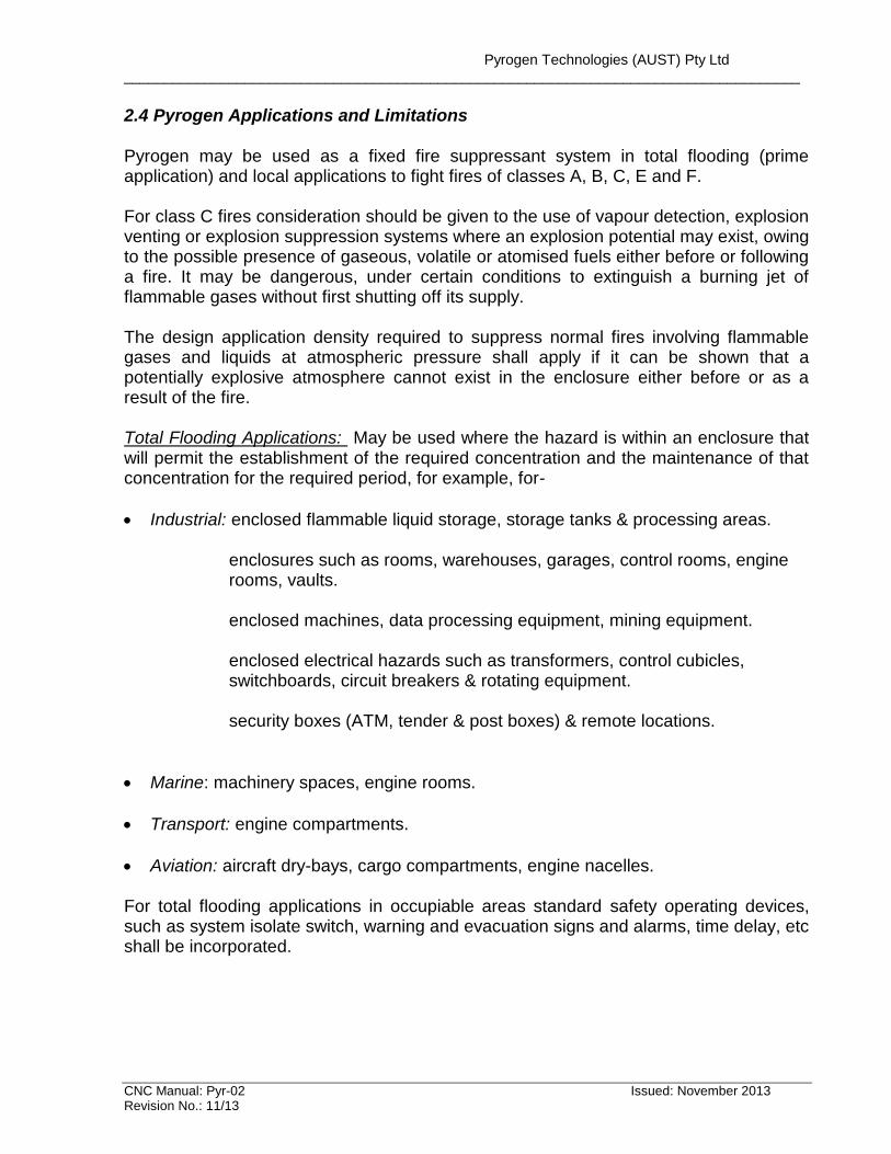
2.4 Pyrogen Applications and Limitations Pyrogen may be used as a fixed fire suppressant system in total flooding (prime application) and local applications to fight fires of classes A, B, C, E and F. For class C fires consideration should be given to the use of vapour detection, explosion venting or explosion suppression systems where an explosion potential may exist, owing to the possible presence of gaseous, volatile or atomised fuels either before or following a fire. It may be dangerous, under certain conditions to extinguish a burning jet of flammable gases without first shutting off its supply. The design application density required to suppress normal fires involving flammable gases and liquids at atmospheric pressure shall apply if it can be shown that a potentially explosive atmosphere cannot exist in the enclosure either before or as a result of the fire. Total Flooding Applications: May be used where the hazard is within an enclosure that will permit the establishment of the required concentration and the maintenance of that concentration for the required period, for example, for-
Industrial: enclosed flammable liquid storage, storage tanks & processing areas. enclosures such as rooms, warehouses, garages, control rooms, engine rooms, vaults. enclosed machines, data processing equipment, mining equipment. enclosed electrical hazards such as transformers, control cubicles, switchboards, circuit breakers & rotating equipment. security boxes (ATM, tender & post boxes) & remote locations.
Marine: machinery spaces, engine rooms.
Transport: engine compartments.
Aviation: aircraft dry-bays, cargo compartments, engine nacelles. For total flooding applications in occupiable areas standard safety operating devices, such as system isolate switch, warning and evacuation signs and alarms, time delay, etc shall be incorporated.
Pyrogen Technologies (AUST) Pty Ltd ____________________________________________________________________________________
CNC Manual: Pyr-02 Issued: November 2013 Revision No.: 11/13
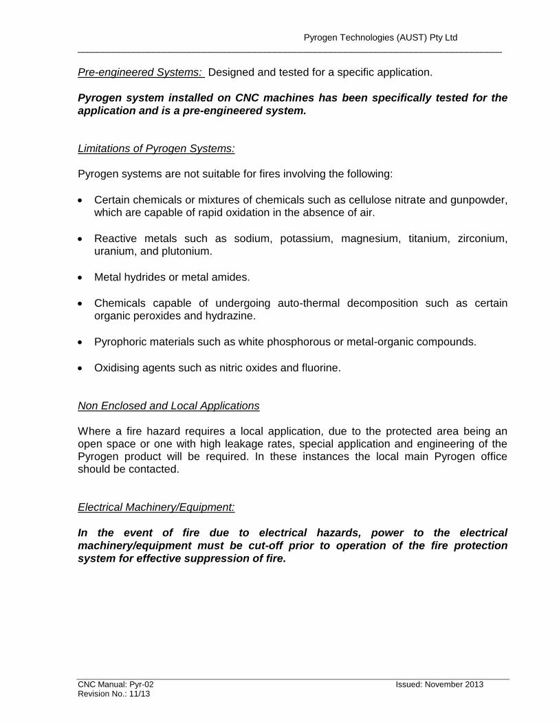
Pre-engineered Systems: Designed and tested for a specific application. Pyrogen system installed on CNC machines has been specifically tested for the application and is a pre-engineered system. Limitations of Pyrogen Systems: Pyrogen systems are not suitable for fires involving the following:
Certain chemicals or mixtures of chemicals such as cellulose nitrate and gunpowder, which are capable of rapid oxidation in the absence of air.
Reactive metals such as sodium, potassium, magnesium, titanium, zirconium, uranium, and plutonium.
Metal hydrides or metal amides.
Chemicals capable of undergoing auto-thermal decomposition such as certain organic peroxides and hydrazine.
Pyrophoric materials such as white phosphorous or metal-organic compounds.
Oxidising agents such as nitric oxides and fluorine. Non Enclosed and Local Applications Where a fire hazard requires a local application, due to the protected area being an open space or one with high leakage rates, special application and engineering of the Pyrogen product will be required. In these instances the local main Pyrogen office should be contacted. Electrical Machinery/Equipment: In the event of fire due to electrical hazards, power to the electrical machinery/equipment must be cut-off prior to operation of the fire protection system for effective suppression of fire.
Pyrogen Technologies (AUST) Pty Ltd ____________________________________________________________________________________
CNC Manual: Pyr-02 Issued: November 2013 Revision No.: 11/13
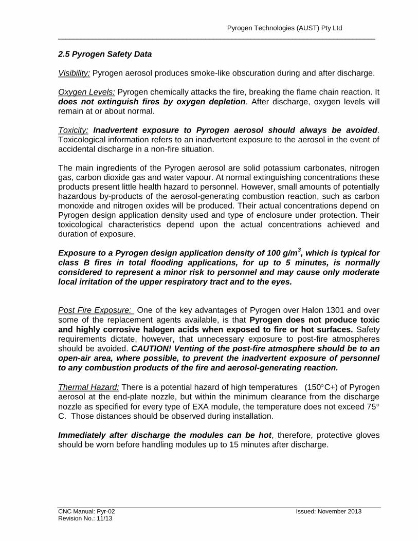
2.5 Pyrogen Safety Data Visibility: Pyrogen aerosol produces smoke-like obscuration during and after discharge. Oxygen Levels: Pyrogen chemically attacks the fire, breaking the flame chain reaction. It
does not extinguish fires by oxygen depletion. After discharge, oxygen levels will remain at or about normal. Toxicity: Inadvertent exposure to Pyrogen aerosol should always be avoided. Toxicological information refers to an inadvertent exposure to the aerosol in the event of accidental discharge in a non-fire situation. The main ingredients of the Pyrogen aerosol are solid potassium carbonates, nitrogen gas, carbon dioxide gas and water vapour. At normal extinguishing concentrations these products present little health hazard to personnel. However, small amounts of potentially hazardous by-products of the aerosol-generating combustion reaction, such as carbon monoxide and nitrogen oxides will be produced. Their actual concentrations depend on Pyrogen design application density used and type of enclosure under protection. Their toxicological characteristics depend upon the actual concentrations achieved and duration of exposure. Exposure to a Pyrogen design application density of 100 g/m
3, which is typical for
class B fires in total flooding applications, for up to 5 minutes, is normally considered to represent a minor risk to personnel and may cause only moderate local irritation of the upper respiratory tract and to the eyes. Post Fire Exposure: One of the key advantages of Pyrogen over Halon 1301 and over
some of the replacement agents available, is that Pyrogen does not produce toxic
and highly corrosive halogen acids when exposed to fire or hot surfaces. Safety requirements dictate, however, that unnecessary exposure to post-fire atmospheres should be avoided. CAUTION! Venting of the post-fire atmosphere should be to an open-air area, where possible, to prevent the inadvertent exposure of personnel to any combustion products of the fire and aerosol-generating reaction.
Thermal Hazard: There is a potential hazard of high temperatures (150C+) of Pyrogen aerosol at the end-plate nozzle, but within the minimum clearance from the discharge
nozzle as specified for every type of EXA module, the temperature does not exceed 75C. Those distances should be observed during installation. Immediately after discharge the modules can be hot, therefore, protective gloves should be worn before handling modules up to 15 minutes after discharge.
Pyrogen Technologies (AUST) Pty Ltd ____________________________________________________________________________________
CNC Manual: Pyr-02 Issued: November 2013 Revision No.: 11/13
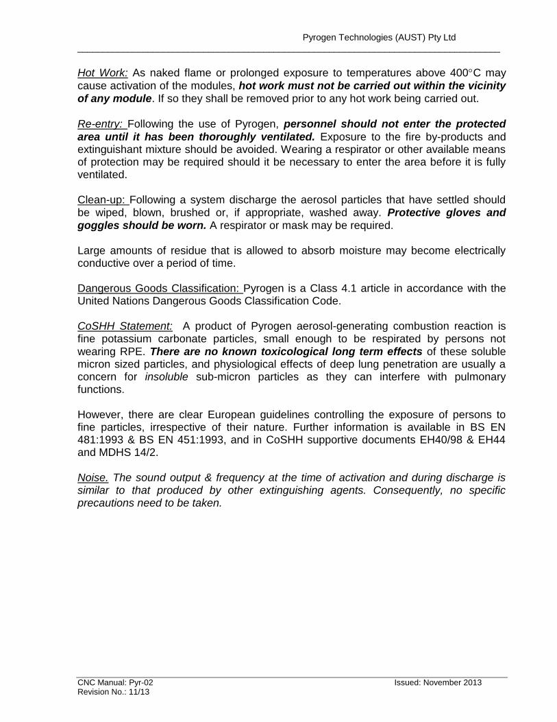
Hot Work: As naked flame or prolonged exposure to temperatures above 400C may
cause activation of the modules, hot work must not be carried out within the vicinity of any module. If so they shall be removed prior to any hot work being carried out. Re-entry: Following the use of Pyrogen, personnel should not enter the protected
area until it has been thoroughly ventilated. Exposure to the fire by-products and extinguishant mixture should be avoided. Wearing a respirator or other available means of protection may be required should it be necessary to enter the area before it is fully ventilated. Clean-up: Following a system discharge the aerosol particles that have settled should be wiped, blown, brushed or, if appropriate, washed away. Protective gloves and goggles should be worn. A respirator or mask may be required. Large amounts of residue that is allowed to absorb moisture may become electrically conductive over a period of time. Dangerous Goods Classification: Pyrogen is a Class 4.1 article in accordance with the United Nations Dangerous Goods Classification Code. CoSHH Statement: A product of Pyrogen aerosol-generating combustion reaction is fine potassium carbonate particles, small enough to be respirated by persons not wearing RPE. There are no known toxicological long term effects of these soluble micron sized particles, and physiological effects of deep lung penetration are usually a concern for insoluble sub-micron particles as they can interfere with pulmonary functions. However, there are clear European guidelines controlling the exposure of persons to fine particles, irrespective of their nature. Further information is available in BS EN 481:1993 & BS EN 451:1993, and in CoSHH supportive documents EH40/98 & EH44 and MDHS 14/2. Noise. The sound output & frequency at the time of activation and during discharge is similar to that produced by other extinguishing agents. Consequently, no specific precautions need to be taken.

Pyrogen Technologies (AUST) Pty Ltd ____________________________________________________________________________________
CNC Manual: Pyr-02 Issued: November 2013 Revision No.: 11/13
2.6 Pyrogen Environmental Characteristics Pyrogen does not affect earth’s ozone layer, since it does not contain chlorine or bromine in its molecular structure. Ozone Depleting Potential (ODP) is a calculated ozone depletion per unit mass of material released relative to a standard, normally CFC-11 (CCl3F). Ozone Depleting Potential (ODP) of Pyrogen is zero. Contribution of Pyrogen to global warming is negligible, since the only one component that could contribute to global warming - carbon dioxide - is present in minor quantities at normal extinguishing concentrations. Global Warming Potential (GWP) is a calculated change is warming resulting from the emission of a unit mass of a chemical relative to that of a reference. In the past CFC-11 was often used as a reference; carbon dioxide is now typically used. The GWP depends on three variables: 1) the integrated infrared radiation absorption spectrum band strength. 2) the location of the infrared bands; and 3) the atmospheric lifetime Global Warming Potential (GWP) of Pyrogen relatively to carbon dioxide is zero.
Pyrogen Technologies (AUST) Pty Ltd ____________________________________________________________________________________
CNC Manual: Pyr-02 Issued: November 2013 Revision No.: 11/13
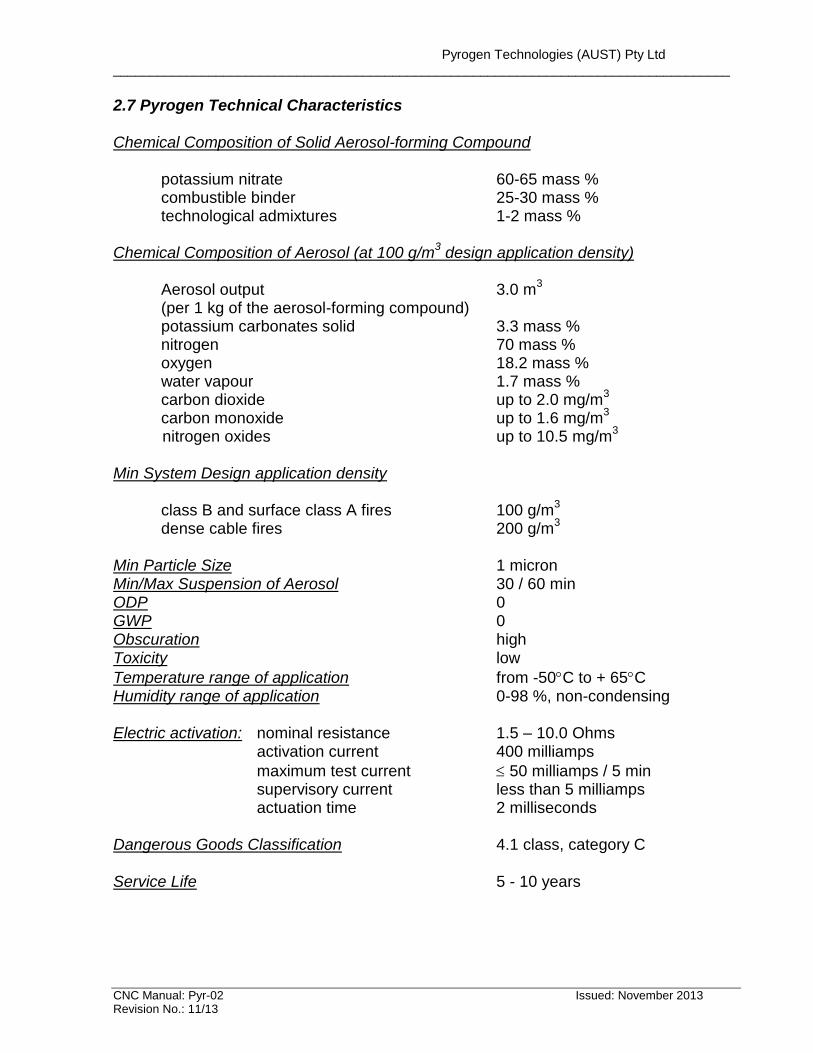
2.7 Pyrogen Technical Characteristics Chemical Composition of Solid Aerosol-forming Compound potassium nitrate 60-65 mass % combustible binder 25-30 mass % technological admixtures 1-2 mass % Chemical Composition of Aerosol (at 100 g/m
3 design application density)
Aerosol output 3.0 m
3
(per 1 kg of the aerosol-forming compound) potassium carbonates solid 3.3 mass %
nitrogen 70 mass % oxygen 18.2 mass % water vapour 1.7 mass % carbon dioxide up to 2.0 mg/m
3
carbon monoxide up to 1.6 mg/m3
nitrogen oxides up to 10.5 mg/m3
Min System Design application density class B and surface class A fires 100 g/m
3
dense cable fires 200 g/m3
Min Particle Size 1 micron Min/Max Suspension of Aerosol 30 / 60 min ODP 0 GWP 0 Obscuration high Toxicity low
Temperature range of application from -50C to + 65C Humidity range of application 0-98 %, non-condensing Electric activation: nominal resistance 1.5 – 10.0 Ohms
activation current 400 milliamps
maximum test current 50 milliamps / 5 min supervisory current less than 5 milliamps actuation time 2 milliseconds Dangerous Goods Classification 4.1 class, category C Service Life 5 - 10 years
Pyrogen Technologies (AUST) Pty Ltd ____________________________________________________________________________________
CNC Manual: Pyr-02 Issued: November 2013 Revision No.: 11/13
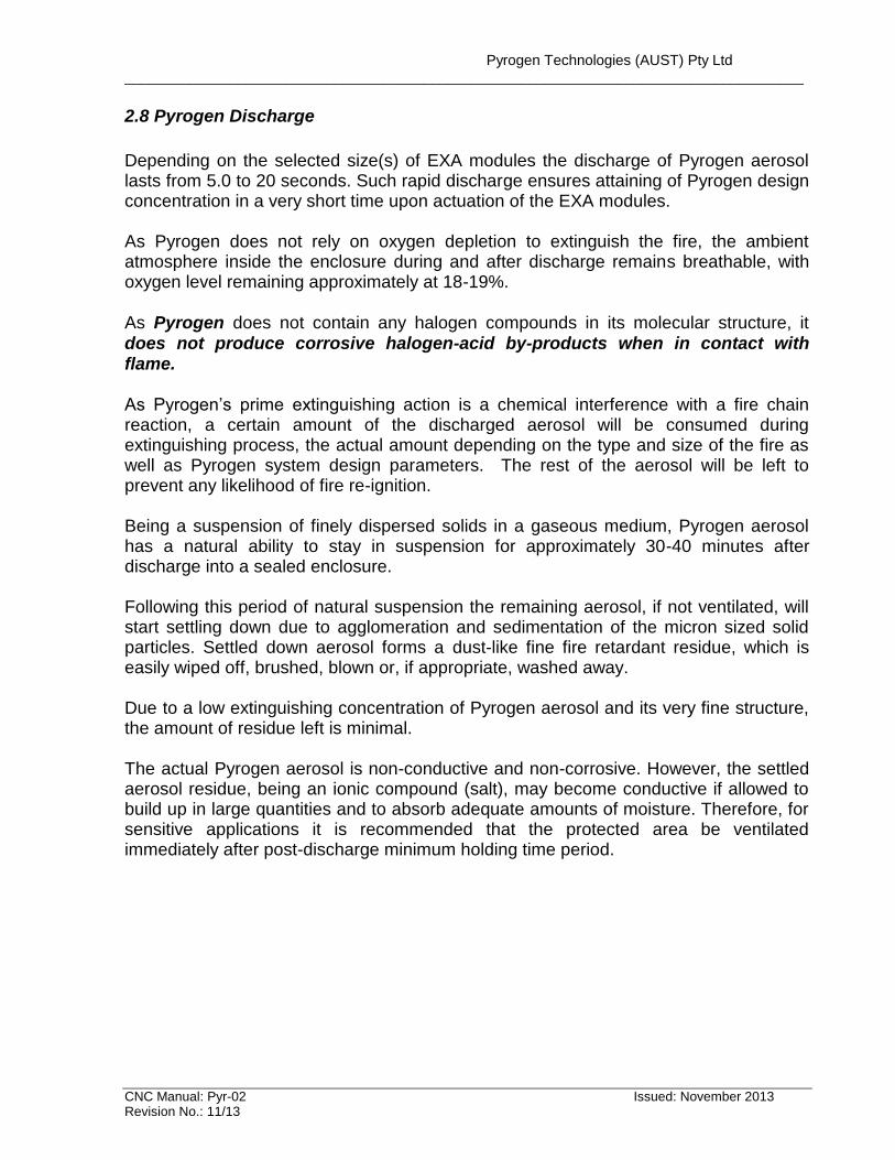
2.8 Pyrogen Discharge
Depending on the selected size(s) of EXA modules the discharge of Pyrogen aerosol lasts from 5.0 to 20 seconds. Such rapid discharge ensures attaining of Pyrogen design concentration in a very short time upon actuation of the EXA modules. As Pyrogen does not rely on oxygen depletion to extinguish the fire, the ambient atmosphere inside the enclosure during and after discharge remains breathable, with oxygen level remaining approximately at 18-19%.
As Pyrogen does not contain any halogen compounds in its molecular structure, it does not produce corrosive halogen-acid by-products when in contact with flame. As Pyrogen’s prime extinguishing action is a chemical interference with a fire chain reaction, a certain amount of the discharged aerosol will be consumed during extinguishing process, the actual amount depending on the type and size of the fire as well as Pyrogen system design parameters. The rest of the aerosol will be left to prevent any likelihood of fire re-ignition. Being a suspension of finely dispersed solids in a gaseous medium, Pyrogen aerosol has a natural ability to stay in suspension for approximately 30-40 minutes after discharge into a sealed enclosure. Following this period of natural suspension the remaining aerosol, if not ventilated, will start settling down due to agglomeration and sedimentation of the micron sized solid particles. Settled down aerosol forms a dust-like fine fire retardant residue, which is easily wiped off, brushed, blown or, if appropriate, washed away. Due to a low extinguishing concentration of Pyrogen aerosol and its very fine structure, the amount of residue left is minimal. The actual Pyrogen aerosol is non-conductive and non-corrosive. However, the settled aerosol residue, being an ionic compound (salt), may become conductive if allowed to build up in large quantities and to absorb adequate amounts of moisture. Therefore, for sensitive applications it is recommended that the protected area be ventilated immediately after post-discharge minimum holding time period.
Pyrogen Technologies (AUST) Pty Ltd ____________________________________________________________________________________
CNC Manual: Pyr-02 Issued: November 2013 Revision No.: 11/13
SECTION 3. SYSTEM SUPPLY
3.1 List of Components
Pre-engineered Pyrogen fire suppression system installed on CNC machines consists of the following components.
1. Pyrogen EXA-MA-5 aerosol module with a single end-plate nozzle; 2. Controller (FireChase CNC detection and activation system) 3. Break Glass with protective cover 4. Thermal Probe Detector 5. Elbow Mounting Unit
3.2 Pyrogen Aerosol Module
Pyrogen products are represented in form of non-pressurised metal canisters, called EXA modules. Each EXA module contains as a minimum an aerosol element, a cooling element, an actuation device and one or two end-plate discharge outlets. Depending on the mass of the aerosol element contained in the module and the module’s dimensions, EXA modules are classified into small range modules and large range modules. Small range modules include EXA-MA-2 and EXA-MA-5 Pyrogen modules. They have been designed to protect CNC enclosures from 2.0 m
3 up to 5.0 m
3.
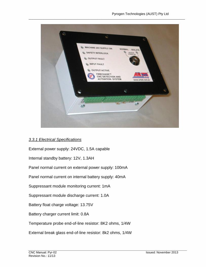
Most of current CNC machines protected with the pre-engineering Pyrogen fire suppression systems use EXA- MA-5 module with a single end-plate discharge nozzle. 3.3 Controller (Fire Panel)
A special fire controller manufactured by ARTEK Engineering Pty Ltd is used in Pyrogen fire suppression systems installed in CNC machines. A photo of the CNC controller is shown below.
Pyrogen Technologies (AUST) Pty Ltd ____________________________________________________________________________________
CNC Manual: Pyr-02 Issued: November 2013 Revision No.: 11/13
3.3.1 Electrical Specifications
External power supply: 24VDC, 1.5A capable Internal standby battery: 12V, 1.3AH Panel normal current on external power supply: 100mA Panel normal current on internal battery supply: 40mA Suppressant module monitoring current: 1mA Suppressant module discharge current: 1.0A Battery float charge voltage: 13.75V Battery charger current limit: 0.8A Temperature probe end-of-line resistor: 8K2 ohms, 1/4W External break glass end-of-line resistor: 8k2 ohms, 1/4W
Pyrogen Technologies (AUST) Pty Ltd ____________________________________________________________________________________
CNC Manual: Pyr-02 Issued: November 2013 Revision No.: 11/13
Time duration for battery support after external power is switch off: 5-6 minutes Monitor contact outputs: E-Stop, normally closed, 2 off Fire System Ready, normally closed, fail-safe Fire System Fault, normally closed 3.3.2 Mechanical Dimensions Fascia dimensions: 180mm long, 130mm high Equipment box dimensions: 153mm long, 103mm high, 83mm deep 3.3.3 Pluggable connectors terminal assignment 12-way 1, 2 External power input, 24VDC, 1 positive, 2 negative 3, 4 Temperature probe input, 8K2 end-of-line 5, 6 Manual break glass input, 8K2 end-of-line 7, 8 E-Stop output contact, normally closed, first set. This output is composed
of 3 normally closed contacts in series, being the alarm relay contact of each input as well as the discharge relay contact.
9, 10 Discharge output 11, 12 Safety door lock input, normally closed 6-way 13, 14 Fire System Ready contact output, normally closed 15, 16 E-Stop output contact, normally closed, second set 17, 18 Fire System Fault contact output, normally closed 3-way 19, 20, 21 Alarm contact output for monitoring, common, normally open and normally closed
Pyrogen Technologies (AUST) Pty Ltd ____________________________________________________________________________________
CNC Manual: Pyr-02 Issued: November 2013 Revision No.: 11/13
3.3.4 Front panel key switch and LEDs When the key switch is turned to NORMAL, and provided the safety door is closed, and there is no fault in the system, the control panel is ready to function. When the key switch is turned to ISOLATE, the discharge circuit is disabled. The alarm and fault sensing functions of the control panel are still active. The alarm sounder volume is reduced to 1/50th when the key switch is turned to this position. DO NOT turn the key switch back to normal if the OUTPUT ACTIVE LED is lit and the sounder is operated, indicating an alarm condition is present. Alarm conditions are not latched, and the panel will go back to normal when the alarm initiating situations are removed. LED functions when lit: MACHINE 24V SUPPLY ON: green, external power supply is available to the panel SAFETY INTERLOCK: amber, safety door is NOT closed, or the key switch NOT on NORMAL OUTPUT FAULT: amber, open circuit on suppressant discharge INPUT FAULT: amber, open circuit on temperature probe or break glass OUTPUT ACTIVE: red, an alarm condition exists NORMAL: green, key switch is on NORMAL, safety door is closed and there is no fault ISOLATE: amber, key switch is on ISOL, discharge circuit is disabled 3.3.5 Operation The fire panel is switched on by the application of the external 24VDC power supply. When the external power is present, the 12V battery is under constant-voltage float charge condition. The battery is used to maintain the panel alive for 5 to 6 minutes after the external power is turned off. The switch-over from external power to internal battery power is seamless, and does not involve any relay operation. At the end of the battery backup period, the panel will be completely switched off, and no current will be drawn from the battery. The continuity of the wiring to the temperature probe, the manual break glass and the suppressant discharge are constantly checked for open-circuit fault. The suppressant discharge is prevented if a fault occurs, as indicated by the amber INPUT FAULT or OUTPUT FAULT LEDs. The sounder will not operate under a fault condition, but the FIRE SYSTEM FAULT output contact will change state from closed to open. The fire system is ready for protection when no fault exists, the key switch is turned to NORMAL, and the safety door is closed. This is indicated by the green NORMAL LED, and by the FIRE SYSTEM READY closed contact output. When the safety door is open, or when the key switch is turned to ISOLATE, the amber SAFETY INTERLOCK LED will be lit, and the SYSTEM READY contact output is open, indicating the system is not ready for discharge.
Pyrogen Technologies (AUST) Pty Ltd ____________________________________________________________________________________
CNC Manual: Pyr-02 Issued: November 2013 Revision No.: 11/13
An alarm condition exists when the temperature probe threshold is exceeded, or when the manual break glass is operated, producing a short-circuit across their respective terminals, and indicated by the OUTPUT ACTIVE red LED, and the sounder. The alarm is not latched, so that if the alarm condition has passed, the panel will go back to normal. The suppressant discharge will occur instantaneously if the fire system is ready. The sounder volume is reduced to a very low level, if the key switch is turned to ISOLATE, and an alarm condition exists with the panel. During periodic tests of the temperature or the break glass, this low level sound is useful as a reminder NOT to turn the key switch to NORMAL until the alarm condition is removed. 3.3.6 Maintenance The fire panel is designed to be as maintenance-free as possible. There are no fuses, and all external connections are current-limited, so that accidental short-circuits will not harm the system. The critical alarm sensing and discharge circuitry contains no electronics. Active components are only used for voltage regulation, fault sensing and battery backup timing. There is no earthing; the complete system is isolated from the metal enclosure.
3.4 Break Glass Manual Break Glass has been designed to manually activate the Pyrogen fire suppression system prior to fire detection by a Thermal Probe Detector. The Manual Break Glass has a protective flap to prevent an inadvertent activation of the Pyrogen system. The Break Glass is connected to the Controller (refer to 3.3 above) allowing activation of a sounder, shutdown of a ventilation fan and other operation functions prior to the Pyrogen system discharge. 3.5 Thermal Probe Detector Thermal probes are used to automatically activate the system in the event of a fire.
Generally, a 302 series automatic heat detectors have been designed for fire detection with alarm systems. Probes of 302 series are self-restoring, sealed, shock and corrosion resistant, nonferrous and of low maintenance. Probes can be mounted horizontally or vertically. They automatically restore when temperatures drop below their rated values They have normally open contacts with a resistor wired across the probe wires to allow monitoring of the circuit by the controller.
Pyrogen Technologies (AUST) Pty Ltd ____________________________________________________________________________________
CNC Manual: Pyr-02 Issued: November 2013 Revision No.: 11/13
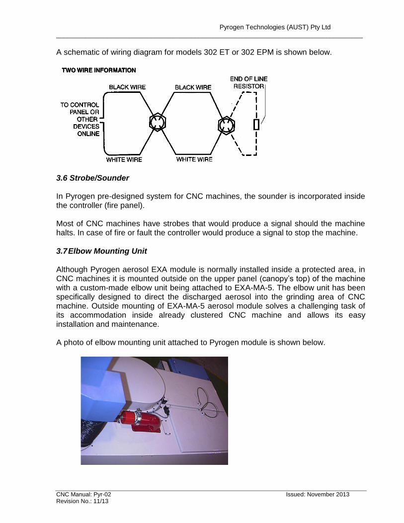
A schematic of wiring diagram for models 302 ET or 302 EPM is shown below.
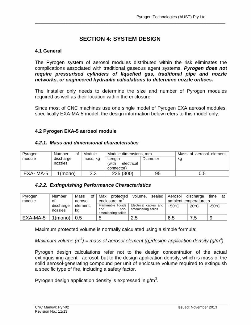
3.6 Strobe/Sounder In Pyrogen pre-designed system for CNC machines, the sounder is incorporated inside the controller (fire panel). Most of CNC machines have strobes that would produce a signal should the machine halts. In case of fire or fault the controller would produce a signal to stop the machine. 3.7 Elbow Mounting Unit Although Pyrogen aerosol EXA module is normally installed inside a protected area, in CNC machines it is mounted outside on the upper panel (canopy’s top) of the machine with a custom-made elbow unit being attached to EXA-MA-5. The elbow unit has been specifically designed to direct the discharged aerosol into the grinding area of CNC machine. Outside mounting of EXA-MA-5 aerosol module solves a challenging task of its accommodation inside already clustered CNC machine and allows its easy installation and maintenance. A photo of elbow mounting unit attached to Pyrogen module is shown below.
Pyrogen Technologies (AUST) Pty Ltd ____________________________________________________________________________________
CNC Manual: Pyr-02 Issued: November 2013 Revision No.: 11/13
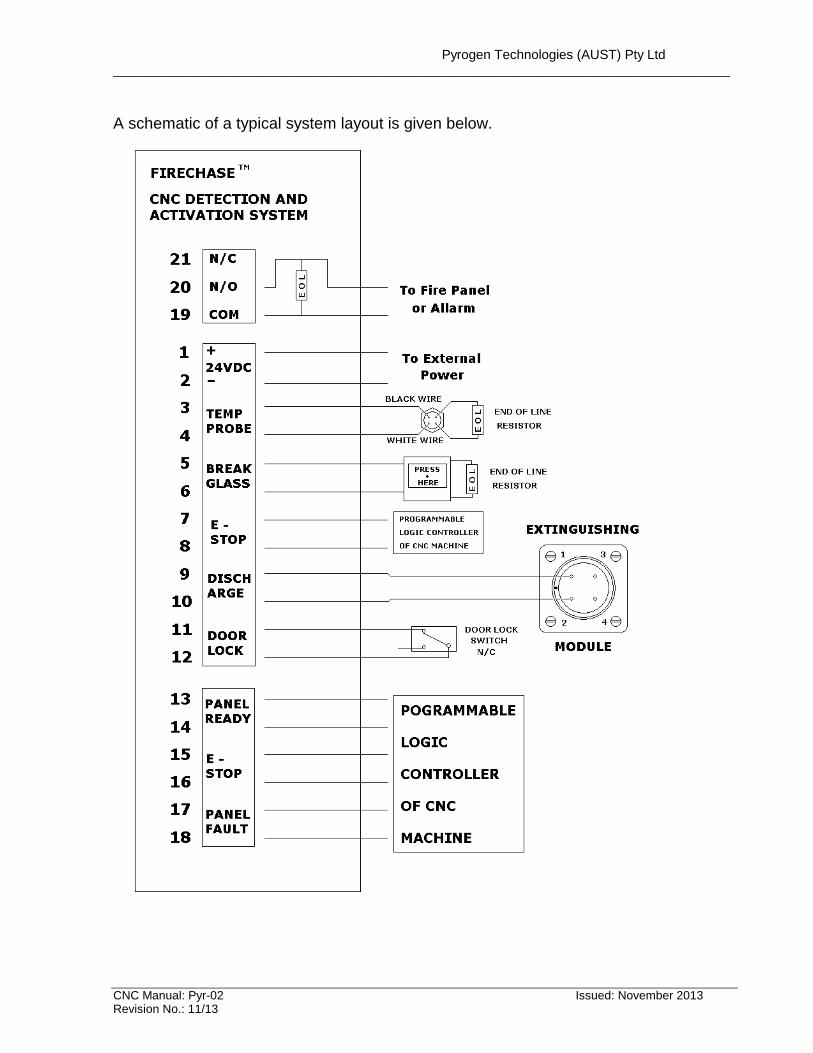
A schematic of a typical system layout is given below.
Pyrogen Technologies (AUST) Pty Ltd ____________________________________________________________________________________
CNC Manual: Pyr-02 Issued: November 2013 Revision No.: 11/13
SECTION 4: SYSTEM DESIGN
4.1 General
The Pyrogen system of aerosol modules distributed within the risk eliminates the complications associated with traditional gaseous agent systems. Pyrogen does not require pressurised cylinders of liquefied gas, traditional pipe and nozzle networks, or engineered hydraulic calculations to determine nozzle orifices. The Installer only needs to determine the size and number of Pyrogen modules required as well as their location within the enclosure. Since most of CNC machines use one single model of Pyrogen EXA aerosol modules, specifically EXA-MA-5 model, the design information below refers to this model only.
4.2 Pyrogen EXA-5 aerosol module
4.2.1. Mass and dimensional characteristics
Pyrogen module
Number of discharge nozzles
Module mass, kg
Module dimensions, mm Mass of aerosol element, kg Length
(with electrical connector)
Diameter
EXA- MA-5 1(mono) 3.3 235 (300) 95 0.5
4.2.2. Extinguishing Performance Characteristics
Pyrogen module
Number of discharge nozzles
Mass of aerosol element, kg
Max protected volume, sealed enclosure, m
3 Aerosol discharge time at ambient temperature, s
Flammable liquids and non-smouldering solids
Electrical cables and smouldering solids
+50C 20C -50C
EXA-MA-5 1(mono) 0.5 5 2.5 6.5 7.5 9
Maximum protected volume is normally calculated using a simple formula: Maximum volume (m
3) = mass of aerosol element (g)/design application density (g/m
3)
Pyrogen design calculations refer not to the design concentration of the actual extinguishing agent - aerosol, but to the design application density, which is mass of the solid aerosol-generating compound per unit of enclosure volume required to extinguish a specific type of fire, including a safety factor. Pyrogen design application density is expressed in g/m
3.
Pyrogen Technologies (AUST) Pty Ltd ____________________________________________________________________________________
CNC Manual: Pyr-02 Issued: November 2013 Revision No.: 11/13
Pyrogen minimum design application density for Class B fires, involving flammable liquids such as petrol, diesel, hydraulic oil and automotive distillate is 100 g/m
3.
Pyrogen minimum design application density for Class A surface fires, involving non-smouldering combustible solids such as wood, textile and ordinary plastics is 100 g/m
3.
Pyrogen minimum design application density for Class A non-surface fires, involving dense cables is 200 g/m
3.
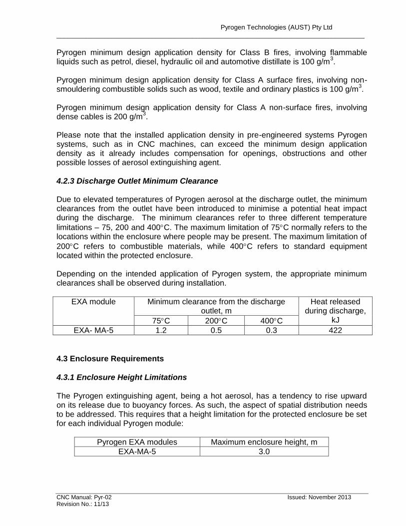
Please note that the installed application density in pre-engineered systems Pyrogen systems, such as in CNC machines, can exceed the minimum design application density as it already includes compensation for openings, obstructions and other possible losses of aerosol extinguishing agent. 4.2.3 Discharge Outlet Minimum Clearance Due to elevated temperatures of Pyrogen aerosol at the discharge outlet, the minimum clearances from the outlet have been introduced to minimise a potential heat impact during the discharge. The minimum clearances refer to three different temperature
limitations – 75, 200 and 400C. The maximum limitation of 75C normally refers to the locations within the enclosure where people may be present. The maximum limitation of
200C refers to combustible materials, while 400C refers to standard equipment located within the protected enclosure. Depending on the intended application of Pyrogen system, the appropriate minimum clearances shall be observed during installation.
EXA module Minimum clearance from the discharge outlet, m
Heat released during discharge,
kJ 75C 200C 400C
EXA- MA-5 1.2 0.5 0.3 422
4.3 Enclosure Requirements 4.3.1 Enclosure Height Limitations
The Pyrogen extinguishing agent, being a hot aerosol, has a tendency to rise upward on its release due to buoyancy forces. As such, the aspect of spatial distribution needs to be addressed. This requires that a height limitation for the protected enclosure be set for each individual Pyrogen module:
Pyrogen EXA modules Maximum enclosure height, m
EXA-MA-5 3.0
Pyrogen Technologies (AUST) Pty Ltd ____________________________________________________________________________________
CNC Manual: Pyr-02 Issued: November 2013 Revision No.: 11/13
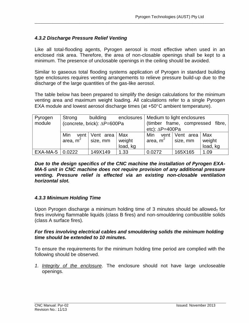
4.3.2 Discharge Pressure Relief Venting
Like all total-flooding agents, Pyrogen aerosol is most effective when used in an enclosed risk area. Therefore, the area of non-closable openings shall be kept to a minimum. The presence of unclosable openings in the ceiling should be avoided. Similar to gaseous total flooding systems application of Pyrogen in standard building type enclosures requires venting arrangements to relieve pressure build-up due to the discharge of the large quantities of the gas-like aerosol. The table below has been prepared to simplify the design calculations for the minimum venting area and maximum weight loading. All calculations refer to a single Pyrogen
EXA module and lowest aerosol discharge times (at +50C ambient temperature).
Pyrogen module
Strong building enclosures
(concrete, brick): P=600Pa
Medium to light enclosures (timber frame, compressed fibre,
etc): P=400Pa
Min vent area, m
2 Vent area size, mm
Max weight load, kg
Min vent area, m
2 Vent area size, mm
Max weight load, kg
EXA-MA-5 0.0222 149X149 1.33 0.0272 165X165 1.09
Due to the design specifics of the CNC machine the installation of Pyrogen EXA- MA-5 unit in CNC machine does not require provision of any additional pressure venting. Pressure relief is effected via an existing non-closable ventilation horizontal slot. 4.3.3 Minimum Holding Time Upon Pyrogen discharge a minimum holding time of 3 minutes should be allowed, for fires involving flammable liquids (class B fires) and non-smouldering combustible solids (class A surface fires). For fires involving electrical cables and smouldering solids the minimum holding time should be extended to 10 minutes. To ensure the requirements for the minimum holding time period are complied with the following should be observed. 1. Integrity of the enclosure. The enclosure should not have large uncloseable
openings.
Pyrogen Technologies (AUST) Pty Ltd ____________________________________________________________________________________
CNC Manual: Pyr-02 Issued: November 2013 Revision No.: 11/13
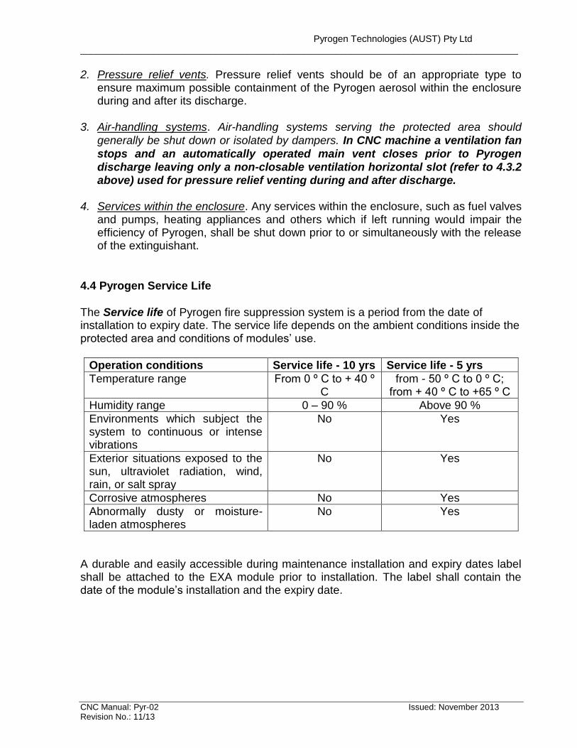
2. Pressure relief vents. Pressure relief vents should be of an appropriate type to ensure maximum possible containment of the Pyrogen aerosol within the enclosure during and after its discharge.
3. Air-handling systems. Air-handling systems serving the protected area should
generally be shut down or isolated by dampers. In CNC machine a ventilation fan
stops and an automatically operated main vent closes prior to Pyrogen discharge leaving only a non-closable ventilation horizontal slot (refer to 4.3.2 above) used for pressure relief venting during and after discharge.
4. Services within the enclosure. Any services within the enclosure, such as fuel valves
and pumps, heating appliances and others which if left running would impair the efficiency of Pyrogen, shall be shut down prior to or simultaneously with the release of the extinguishant.
4.4 Pyrogen Service Life The Service life of Pyrogen fire suppression system is a period from the date of installation to expiry date. The service life depends on the ambient conditions inside the protected area and conditions of modules’ use.
Operation conditions Service life - 10 yrs Service life - 5 yrs
Temperature range From 0 º C to + 40 º C
from - 50 º C to 0 º C; from + 40 º C to +65 º C
Humidity range 0 – 90 % Above 90 %
Environments which subject the system to continuous or intense vibrations
No Yes
Exterior situations exposed to the sun, ultraviolet radiation, wind, rain, or salt spray
No Yes
Corrosive atmospheres No Yes
Abnormally dusty or moisture-laden atmospheres
No Yes
A durable and easily accessible during maintenance installation and expiry dates label shall be attached to the EXA module prior to installation. The label shall contain the date of the module’s installation and the expiry date.
Pyrogen Technologies (AUST) Pty Ltd ____________________________________________________________________________________
CNC Manual: Pyr-02 Issued: November 2013 Revision No.: 11/13
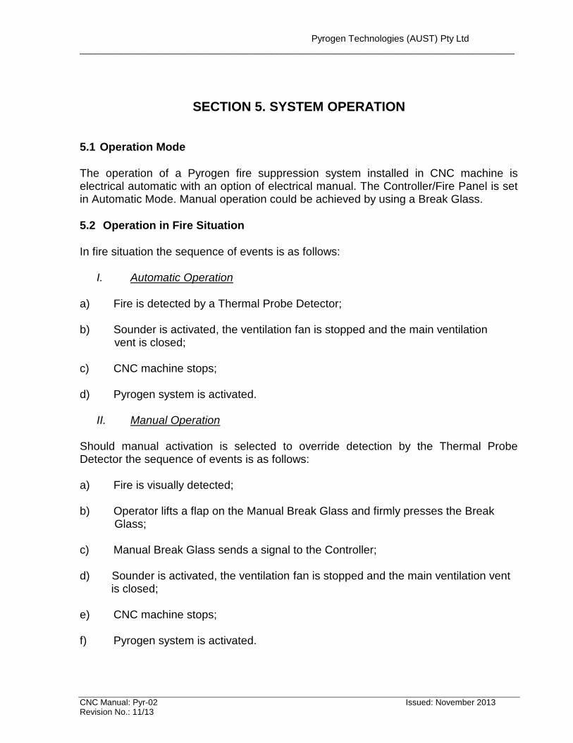
SECTION 5. SYSTEM OPERATION
5.1 Operation Mode
The operation of a Pyrogen fire suppression system installed in CNC machine is electrical automatic with an option of electrical manual. The Controller/Fire Panel is set in Automatic Mode. Manual operation could be achieved by using a Break Glass.
5.2 Operation in Fire Situation
In fire situation the sequence of events is as follows:
I. Automatic Operation
a) Fire is detected by a Thermal Probe Detector; b) Sounder is activated, the ventilation fan is stopped and the main ventilation vent is closed; c) CNC machine stops; d) Pyrogen system is activated.
II. Manual Operation
Should manual activation is selected to override detection by the Thermal Probe Detector the sequence of events is as follows: a) Fire is visually detected; b) Operator lifts a flap on the Manual Break Glass and firmly presses the Break Glass; c) Manual Break Glass sends a signal to the Controller; d) Sounder is activated, the ventilation fan is stopped and the main ventilation vent is closed; e) CNC machine stops; f) Pyrogen system is activated.
Pyrogen Technologies (AUST) Pty Ltd ____________________________________________________________________________________
CNC Manual: Pyr-02 Issued: November 2013 Revision No.: 11/13
SECTION 6. SYSTEM INSTALLATION 6.1 Design & Acceptance Documentation a) Form 1 - System Design Approval Certificate Please refer to Appendix A - form 1. Pyrogen System Design Approval Certificate is to be completed by the contractor prior to installation. A copy of the certificate shall be forwarded to Pyrogen Office or the Pyrogen Distributor and, where required, to an appropriate authority. b) Form 2 – Commissioning and Acceptance Test Report Please refer to Appendix A – form 2. The installed Pyrogen system is to be commissioned by the contractor in accordance with the Commissioning Check list. On completion and acceptance of the commissioning, the installation contractor shall issue a commissioning test report in accordance with Form 2. A copy of the report shall be forwarded to the Pyrogen Office/ Distributor. c) Form 3 – Notice of Completion Please refer to Appendix A – form 3. Shall be completed by the installation contractor following the commissioning check. A copy of the form shall be forwarded to the Pyrogen Office/Distributor. d) Form 4 – Maintenance Check List
Form 5 - Annual Maintenance Certificate Please refer to Appendix A – forms 4 and 5. Shall be completed by the installation contractor after regular annual maintenance of the installed system. A copy of each form shall be forwarded to the Pyrogen Office/Distributor.
Pyrogen Technologies (AUST) Pty Ltd ____________________________________________________________________________________
CNC Manual: Pyr-02 Issued: November 2013 Revision No.: 11/13
6.2 System Integrity It is important that prior to the installation of the EXA module the integrity and resistance of the electric activation circuit for each EXA module is checked with the use
of a digital multi-meter. The maximum test current shall not exceed 50 milliamps for a period of 5 minutes. The monitoring current shall not exceed 5 milliamps. Resistance of the electric activation circuit shall be within 1.5-10.0 Ohms. It is also important to check earth fault of every EXA module. Earth fault resistance must not be less than 0.1 MOhm. 6.3 Prior to Installation Before commencing the installation: System components Ensure completeness of the Pyrogen system, including accessories. Please refer to the completed System Design Approval Certificate (form 1, Appendix A) for identification. EXA-MA-5 aerosol module Check that there is no sign of corrosion on the module’s casing and that a plastic membrane covering a discharge outlet is intact. Service life labels Attach the installation and expiry date label to EXA-MA-5 module. Ensure the service life is in accordance with the system’s operation conditions (refer to 4.4).
Pyrogen Technologies (AUST) Pty Ltd ____________________________________________________________________________________
CNC Manual: Pyr-02 Issued: November 2013 Revision No.: 11/13
6.4 Installation Location The Pyrogen EXA module should be installed in the best possible position to ensure:
- Pyrogen aerosol is mixed evenly and contained within the protected area; - Minimum clearance form the discharge outlet as specified in 4.2.3 is observed;
- Pyrogen module is not directed towards sensitive or delicate instrumentation;
- Possible exposure to high temperatures (above +50C) or high humidity is avoided;
- Close proximity to exit or potential human exposure areas or outlets is avoided; - Close proximity to unavoidable non-closable openings is avoided;
6.5 Mounting The EXA-MA-5 module is mounted to the CNC machine via an elbow unit. Ensure the EXA-MA-5 module is firmly and reliably attached to the elbow unit and the elbow unit is firmly attached to the CNC machine.
Warning! Loose mounting may result in EXA- MA-5 module being propelled out of
the elbow unit or its detachment from the CNC machine during system discharge. 6.6 Electric Wiring The following minimum requirements to the electrical wiring should apply:
- Cables should be fire-resistant. Conductors should be of copper, each having a cross-sectional area of not less than 1 mm
2, or if stranded, not less than 0.5
mm2. Should there be any possibility of the mechanical damage, the cables shall
be enclosed into a plastic or metal conduit. All cabling shall be grounded in accordance with standard requirements.
- A standard power source that provides at least 2 Amp current and 24 Volts
voltage shall be used. The power source shall have a backup power supply.
For CNC installation a backup power supply is already incorporated inside the Controller. Due to specific design requirements for CNC machines the backup power supply to the Controller is disconnected 5 minutes after the CNC machine shutdown.
Pyrogen Technologies (AUST) Pty Ltd ____________________________________________________________________________________
CNC Manual: Pyr-02 Issued: November 2013 Revision No.: 11/13
The wiring procedure should be as follows:
- Install electrical wiring; - Install and connect such devices as strobe/sounder, manual break glass,
Controller, detectors, etc;
- Connect a miniature filament lamp with 12 Volts voltage and current up to 50mA in place of EXA module;
- Ensure the manual break glass has a protective flap to avoid the accidental discharge;
- Connect the circuit to a power supply;
- Activate the system. All devices shall operate and the lamp shall glow. Should
the system fail to operate properly, disconnect the power supply, check connections between the devices, reconnect the power supply and try again;
- Reset the system. The lamp shall be switched off;
WARNING! Prior to connecting EXA module ensure the wires leading to the module are not carrying voltage. Connection of EXA module(s) should always be the last function in electrical wiring procedure.
- Disconnect the lamp and connect the EXA module in its place. Install EXA module in accordance with the installation recommendations;
Pyrogen Technologies (AUST) Pty Ltd ____________________________________________________________________________________
CNC Manual: Pyr-02 Issued: November 2013 Revision No.: 11/13
2
1 4
3
1
2 3
4
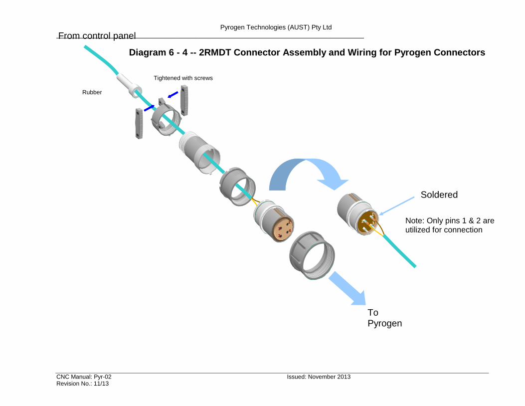
To Pyrogen generator
From control panel
Soldered
Note: Only pins 1 & 2 are utilized for connection
Rubber holder
Tightened with screws
Diagram 6 - 4 -- 2RMDT Connector Assembly and Wiring for Pyrogen Connectors
Pyrogen Technologies (AUST) Pty Ltd ____________________________________________________________________________________
CNC Manual: Pyr-02 Issued: November 2013 Revision No.: 11/13
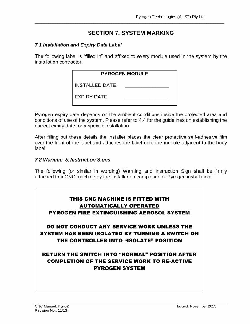
SECTION 7. SYSTEM MARKING 7.1 Installation and Expiry Date Label The following label is “filled in” and affixed to every module used in the system by the installation contractor.
PYROGEN MODULE
INSTALLED DATE: ________________
EXPIRY DATE: ________________
Pyrogen expiry date depends on the ambient conditions inside the protected area and conditions of use of the system. Please refer to 4.4 for the guidelines on establishing the correct expiry date for a specific installation. After filling out these details the installer places the clear protective self-adhesive film over the front of the label and attaches the label onto the module adjacent to the body label. 7.2 Warning & Instruction Signs The following (or similar in wording) Warning and Instruction Sign shall be firmly attached to a CNC machine by the installer on completion of Pyrogen installation.
THIS CNC MACHINE IS FITTED WITH
AUTOMATICALLY OPERATED
PYROGEN FIRE EXTINGUISHING AEROSOL SYSTEM
DO NOT CONDUCT ANY SERVICE WORK UNLESS THE
SYSTEM HAS BEEN ISOLATED BY TURNING A SWITCH ON
THE CONTROLLER INTO “ISOLATE” POSITION
RETURN THE SWITCH INTO “NORMAL” POSITION AFTER
COMPLETION OF THE SERVICE WORK TO RE-ACTIVE
PYROGEN SYSTEM
Pyrogen Technologies (AUST) Pty Ltd ____________________________________________________________________________________
CNC Manual: Pyr-02 Issued: November 2013 Revision No.: 11/13
SECTION 8. SYSTEM COMMISSIONING The completed Pyrogen installation shall be commissioned in accordance with Commissioning Checklist attached in Appendix A (Form 2). On completion and acceptance of the commissioning procedure, the installation contractor shall issue a Notice of Completion in Appendix A (Form 3). Commissioning should be carried out by trained and authorised personnel only.
SECTION 9. SYSTEM MAINTENANCE The user of the installation should ensure that the system is in good working order at all times. The user should carry out monthly inspections of the fire suppression equipment. This should include looking out for obstruction of the discharge nozzle, extension/alteration of the protected enclosure, openings left unclosed that were not catered for during design, and that the position and orientation of the Pyrogen modules remain in the designed position. The installation should be inspected at least once a year by an authorised inspector. The inspection plan should include all components of the system and parts of the premises necessary for the effective operation of the system. A system maintenance log should be kept and status of every maintenance visit is recorded. For a typical system maintenance report refer to the attached Maintenance Checklist in Appendix A (Form 4).
Periodic check-up is required for electrical circuitry of Pyrogen system. The following steps shall be undertaken: If the control system is designed to transmit alarm signals to a remote manned centre, always ensure that the link is disabled, or in the event that disabling the link is not an option, it would be essential to notify the centre before undertaking the test. Occupant of the premises should also be notified that the system test might result in the sounders being activated. WARNING! Prior to the start of ANY maintenance work, always ensure as the first step, that the wiring to the Pyrogen module has been electrically isolated. Failure to do so may result in unwanted spurious discharge.
Pyrogen Technologies (AUST) Pty Ltd ____________________________________________________________________________________
CNC Manual: Pyr-02 Issued: November 2013 Revision No.: 11/13
The maintenance procedure is as follows. 1) Disconnect the wiring at the EXA module. This is extremely important to ensure that the module has not inadvertently been left connected. 2) Connect a miniature filament lamp with 24 Volts voltage and current up to 50 mA in place of EXA module. 3) Connect the circuit to a power supply. 4) Activate the system. All devices shall operate and the lamp shall glow. Should the system fail to operate properly, disconnect the power supply, check connections between devices, reconnect the power supply and try again. 5) Reset the system. The lamp shall be switched off. WARNING! Prior to connecting EXA module, ensure the wires leading to the module are not carrying voltage. Connection of EXA module should always be the last function in electrical wiring procedure.
6) Disconnect the lamp and connect the EXA module in its place. Install EXA modules
in accordance with installation recommendations.
Pyrogen Technologies (AUST) Pty Ltd ____________________________________________________________________________________
CNC Manual: Pyr-02 Issued: November 2013 Revision No.: 11/13
APPENDIX A -- APPROVAL DOCUMENTATION
PYROGEN FIXED FIRE SUPPRESSION SYSTEM
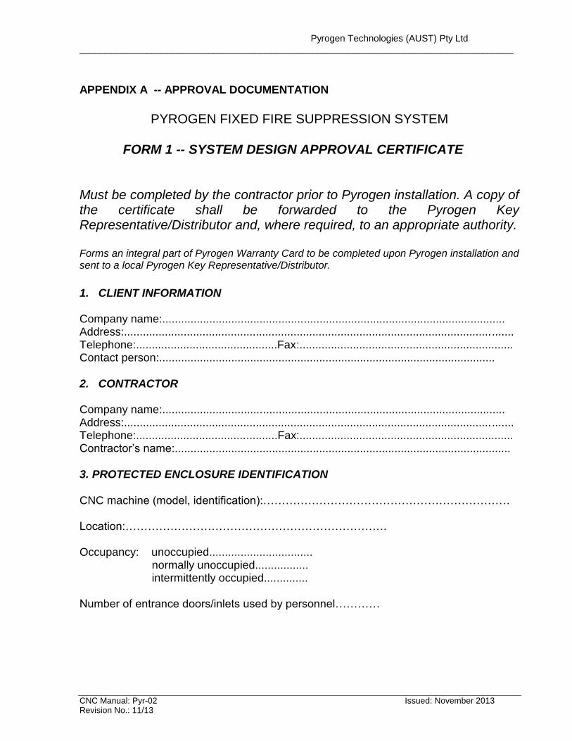
FORM 1 -- SYSTEM DESIGN APPROVAL CERTIFICATE
Must be completed by the contractor prior to Pyrogen installation. A copy of the certificate shall be forwarded to the Pyrogen Key Representative/Distributor and, where required, to an appropriate authority. Forms an integral part of Pyrogen Warranty Card to be completed upon Pyrogen installation and sent to a local Pyrogen Key Representative/Distributor.
1. CLIENT INFORMATION Company name:............................................................................................................. Address:............................................................................................................................ Telephone:.............................................Fax:.................................................................... Contact person:........................................................................................................... 2. CONTRACTOR Company name:............................................................................................................. Address:............................................................................................................................ Telephone:.............................................Fax:.................................................................... Contractor’s name:........................................................................................................... 3. PROTECTED ENCLOSURE IDENTIFICATION CNC machine (model, identification):………………………………………………………… Location:……………………………………………………………. Occupancy: unoccupied................................. normally unoccupied................. intermittently occupied.............. Number of entrance doors/inlets used by personnel…………
Pyrogen Technologies (AUST) Pty Ltd ____________________________________________________________________________________
CNC Manual: Pyr-02 Issued: November 2013 Revision No.: 11/13
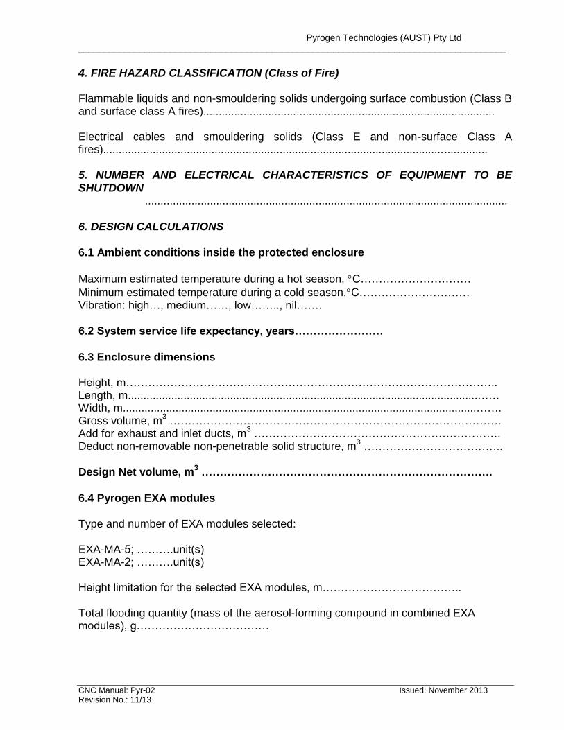
4. FIRE HAZARD CLASSIFICATION (Class of Fire) Flammable liquids and non-smouldering solids undergoing surface combustion (Class B and surface class A fires).............................................................................................. Electrical cables and smouldering solids (Class E and non-surface Class A fires)............................................................................................................................ 5. NUMBER AND ELECTRICAL CHARACTERISTICS OF EQUIPMENT TO BE SHUTDOWN
..................................................................................................................... 6. DESIGN CALCULATIONS
6.1 Ambient conditions inside the protected enclosure
Maximum estimated temperature during a hot season, C…………………………
Minimum estimated temperature during a cold season,C………………………… Vibration: high…, medium……, low…….., nil…….
6.2 System service life expectancy, years……………………
6.3 Enclosure dimensions Height, m……………………………………………………………………………………….. Length, m.................................................................................................................…… Width, m..................................................................................................................……. Gross volume, m
3 ………………………………………………………………………………
Add for exhaust and inlet ducts, m3 ………………………………………………………….
Deduct non-removable non-penetrable solid structure, m3 ………………………………..
Design Net volume, m3 …………………………………………………………………….
6.4 Pyrogen EXA modules
Type and number of EXA modules selected: EXA-MA-5; ……….unit(s) EXA-MA-2; ……….unit(s) Height limitation for the selected EXA modules, m……………………………….. Total flooding quantity (mass of the aerosol-forming compound in combined EXA modules), g………………………………
Pyrogen Technologies (AUST) Pty Ltd ____________________________________________________________________________________
CNC Manual: Pyr-02 Issued: November 2013 Revision No.: 11/13
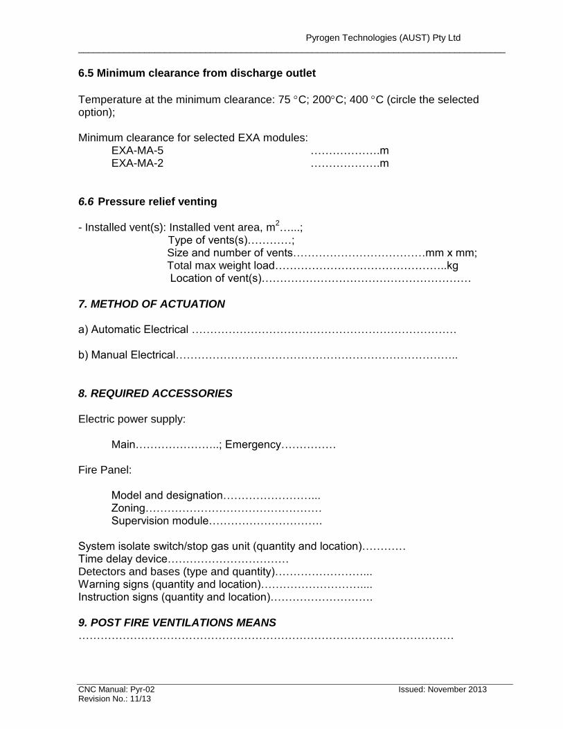
6.5 Minimum clearance from discharge outlet
Temperature at the minimum clearance: 75 C; 200C; 400 C (circle the selected option); Minimum clearance for selected EXA modules:
EXA-MA-5 ……………….m EXA-MA-2 ……………….m
6.6 Pressure relief venting
- Installed vent(s): Installed vent area, m
2…...;
Type of vents(s)…………; Size and number of vents………………………………mm x mm; Total max weight load………………………………………..kg Location of vent(s)…………………………………………………
7. METHOD OF ACTUATION a) Automatic Electrical ……………………………………………………………… b) Manual Electrical………………………………………………………………….. 8. REQUIRED ACCESSORIES Electric power supply:
Main…………………..; Emergency…………… Fire Panel:
Model and designation……………………... Zoning………………………………………… Supervision module………………………….
System isolate switch/stop gas unit (quantity and location)………… Time delay device…………………………… Detectors and bases (type and quantity)……………………... Warning signs (quantity and location)……………………….... Instruction signs (quantity and location)………………………. 9. POST FIRE VENTILATIONS MEANS …………………………………………………………………………………………
Pyrogen Technologies (AUST) Pty Ltd ____________________________________________________________________________________
CNC Manual: Pyr-02 Issued: November 2013 Revision No.: 11/13
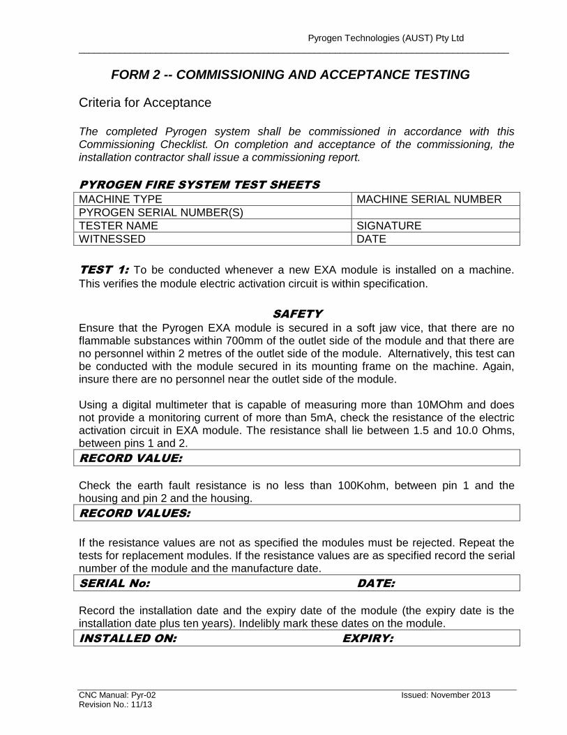
FORM 2 -- COMMISSIONING AND ACCEPTANCE TESTING
Criteria for Acceptance The completed Pyrogen system shall be commissioned in accordance with this Commissioning Checklist. On completion and acceptance of the commissioning, the installation contractor shall issue a commissioning report.
PYROGEN FIRE SYSTEM TEST SHEETS
MACHINE TYPE MACHINE SERIAL NUMBER
PYROGEN SERIAL NUMBER(S)
TESTER NAME SIGNATURE
WITNESSED DATE
TEST 1: To be conducted whenever a new EXA module is installed on a machine.
This verifies the module electric activation circuit is within specification.
SAFETY
Ensure that the Pyrogen EXA module is secured in a soft jaw vice, that there are no flammable substances within 700mm of the outlet side of the module and that there are no personnel within 2 metres of the outlet side of the module. Alternatively, this test can be conducted with the module secured in its mounting frame on the machine. Again, insure there are no personnel near the outlet side of the module. Using a digital multimeter that is capable of measuring more than 10MOhm and does not provide a monitoring current of more than 5mA, check the resistance of the electric activation circuit in EXA module. The resistance shall lie between 1.5 and 10.0 Ohms, between pins 1 and 2.
RECORD VALUE:
Check the earth fault resistance is no less than 100Kohm, between pin 1 and the housing and pin 2 and the housing.
RECORD VALUES:
If the resistance values are not as specified the modules must be rejected. Repeat the tests for replacement modules. If the resistance values are as specified record the serial number of the module and the manufacture date.
SERIAL No: DATE:
Record the installation date and the expiry date of the module (the expiry date is the installation date plus ten years). Indelibly mark these dates on the module.
INSTALLED ON: EXPIRY:
Pyrogen Technologies (AUST) Pty Ltd ____________________________________________________________________________________
CNC Manual: Pyr-02 Issued: November 2013 Revision No.: 11/13
Insert the module in its mounting elbow and check that it is held securely when the clamp is tightened. Do not connect the module plug as this stage. Retain this tests sheet in the machine folder. When all other tests are complete and the machine is fully installed, check that there is no voltage on the module line (pins 1 and 2) and plus the connector into the module.
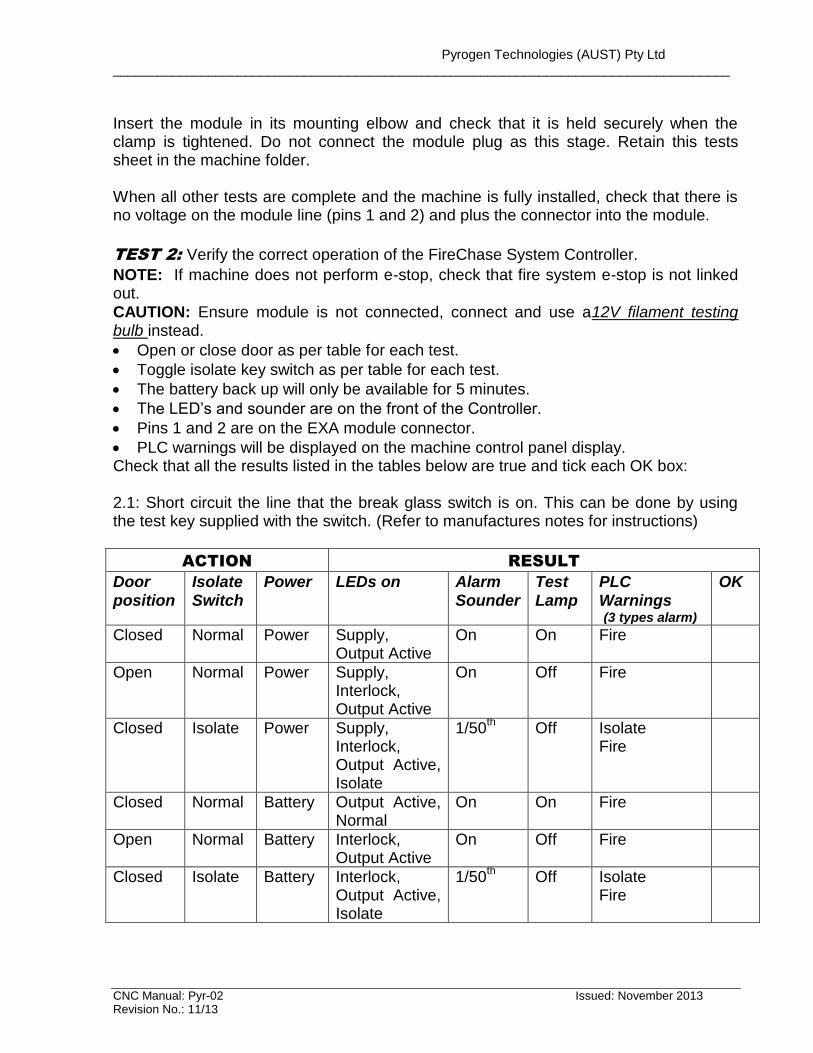
TEST 2: Verify the correct operation of the FireChase System Controller.
NOTE: If machine does not perform e-stop, check that fire system e-stop is not linked out.
CAUTION: Ensure module is not connected, connect and use a12V filament testing bulb instead.
Open or close door as per table for each test.
Toggle isolate key switch as per table for each test.
The battery back up will only be available for 5 minutes.
The LED’s and sounder are on the front of the Controller.
Pins 1 and 2 are on the EXA module connector.
PLC warnings will be displayed on the machine control panel display. Check that all the results listed in the tables below are true and tick each OK box: 2.1: Short circuit the line that the break glass switch is on. This can be done by using the test key supplied with the switch. (Refer to manufactures notes for instructions)
ACTION RESULT
Door position
Isolate Switch
Power LEDs on Alarm Sounder
Test Lamp
PLC Warnings (3 types alarm)
OK
Closed Normal Power Supply, Output Active
On On Fire
Open Normal Power Supply, Interlock, Output Active
On Off Fire
Closed Isolate Power Supply, Interlock, Output Active, Isolate
1/50th
Off Isolate Fire
Closed Normal Battery Output Active, Normal
On On Fire
Open Normal Battery Interlock, Output Active
On Off Fire
Closed Isolate Battery Interlock, Output Active, Isolate
1/50th
Off Isolate Fire
Pyrogen Technologies (AUST) Pty Ltd ____________________________________________________________________________________
CNC Manual: Pyr-02 Issued: November 2013 Revision No.: 11/13
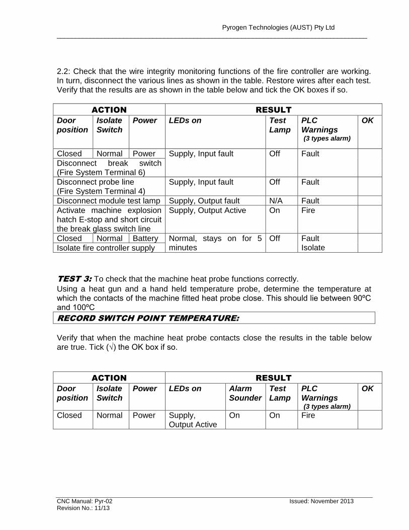
2.2: Check that the wire integrity monitoring functions of the fire controller are working. In turn, disconnect the various lines as shown in the table. Restore wires after each test. Verify that the results are as shown in the table below and tick the OK boxes if so.
ACTION RESULT
Door position
Isolate Switch
Power LEDs on Test Lamp
PLC Warnings (3 types alarm)
OK
Closed Normal Power Supply, Input fault Off Fault
Disconnect break switch (Fire System Terminal 6)
Disconnect probe line (Fire System Terminal 4)
Supply, Input fault Off Fault
Disconnect module test lamp Supply, Output fault N/A Fault
Activate machine explosion hatch E-stop and short circuit the break glass switch line
Supply, Output Active On Fire
Closed Normal Battery Normal, stays on for 5 minutes
Off Fault Isolate
Isolate fire controller supply
TEST 3: To check that the machine heat probe functions correctly.
Using a heat gun and a hand held temperature probe, determine the temperature at which the contacts of the machine fitted heat probe close. This should lie between 90ºC and 100ºC
RECORD SWITCH POINT TEMPERATURE:
Verify that when the machine heat probe contacts close the results in the table below are true. Tick (√) the OK box if so.
ACTION RESULT
Door position
Isolate Switch
Power LEDs on Alarm Sounder
Test Lamp
PLC Warnings (3 types alarm)
OK
Closed Normal Power Supply, Output Active
On On Fire
Pyrogen Technologies (AUST) Pty Ltd ____________________________________________________________________________________
CNC Manual: Pyr-02 Issued: November 2013 Revision No.: 11/13
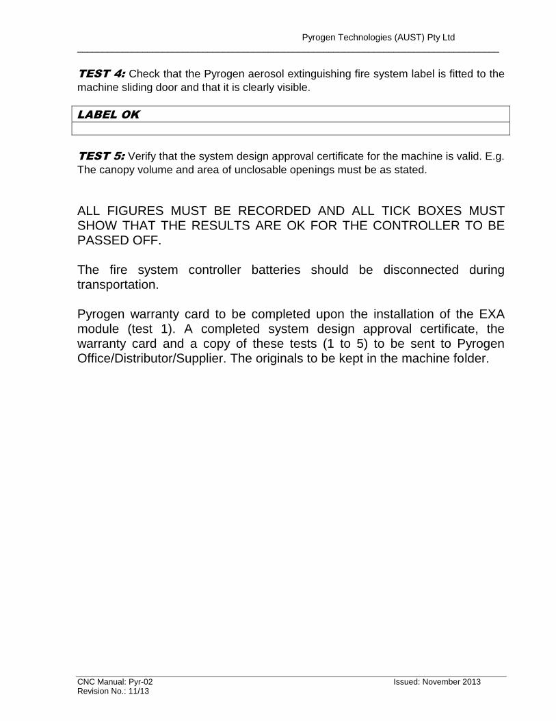
TEST 4: Check that the Pyrogen aerosol extinguishing fire system label is fitted to the
machine sliding door and that it is clearly visible.
LABEL OK
TEST 5: Verify that the system design approval certificate for the machine is valid. E.g.
The canopy volume and area of unclosable openings must be as stated.
ALL FIGURES MUST BE RECORDED AND ALL TICK BOXES MUST SHOW THAT THE RESULTS ARE OK FOR THE CONTROLLER TO BE PASSED OFF. The fire system controller batteries should be disconnected during transportation. Pyrogen warranty card to be completed upon the installation of the EXA module (test 1). A completed system design approval certificate, the warranty card and a copy of these tests (1 to 5) to be sent to Pyrogen Office/Distributor/Supplier. The originals to be kept in the machine folder.
Pyrogen Technologies (AUST) Pty Ltd ____________________________________________________________________________________
CNC Manual: Pyr-02 Issued: November 2013 Revision No.: 11/13
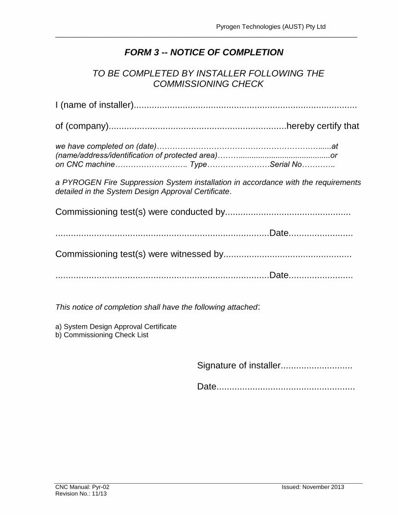
FORM 3 -- NOTICE OF COMPLETION
TO BE COMPLETED BY INSTALLER FOLLOWING THE COMMISSIONING CHECK
I (name of installer)....................................................................................... of (company).....................................................................hereby certify that we have completed on (date)……………………………………………………….....at (name/address/identification of protected area)……….........................................or on CNC machine………………………. Type……………………Serial No…………. a PYROGEN Fire Suppression System installation in accordance with the requirements detailed in the System Design Approval Certificate.
Commissioning test(s) were conducted by................................................. ...................................................................................Date......................... Commissioning test(s) were witnessed by.................................................. ...................................................................................Date......................... This notice of completion shall have the following attached: a) System Design Approval Certificate b) Commissioning Check List Signature of installer............................ Date......................................................
Pyrogen Technologies (AUST) Pty Ltd ____________________________________________________________________________________
CNC Manual: Pyr-02 Issued: November 2013 Revision No.: 11/13
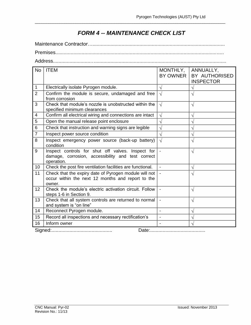
FORM 4 -- MAINTENANCE CHECK LIST
Maintenance Contractor…................................................................................................
Premises..........................................................................................................................
Address...........................…...............................................................................................
No ITEM MONTHLY, BY OWNER
ANNUALLY, BY AUTHORISED INSPECTOR
1 Electrically isolate Pyrogen module.
2 Confirm the module is secure, undamaged and free from corrosion
3 Check that module’s nozzle is unobstructed within the specified minimum clearances
4 Confirm all electrical wiring and connections are intact
5 Open the manual release point enclosure
6 Check that instruction and warning signs are legible
7 Inspect power source condition
8 Inspect emergency power source (back-up battery) condition
9 Inspect controls for shut off valves. Inspect for damage, corrosion, accessibility and test correct operation.
-
10 Check the post fire ventilation facilities are functional. -
11 Check that the expiry date of Pyrogen module will not occur within the next 12 months and report to the owner.
-
12 Check the module’s electric activation circuit. Follow steps 1-6 in Section 9.
-
13 Check that all system controls are returned to normal and system is “on line”
-
14 Reconnect Pyrogen module. -
15 Record all inspections and necessary rectification’s -
16 Inform owner -
Signed:............................................ Date:........................................
Pyrogen Technologies (AUST) Pty Ltd ____________________________________________________________________________________
CNC Manual: Pyr-02 Issued: November 2013 Revision No.: 11/13
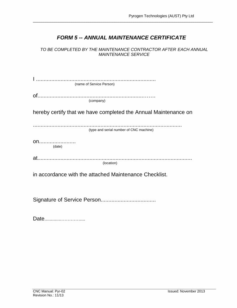
FORM 5 -- ANNUAL MAINTENANCE CERTIFICATE
TO BE COMPLETED BY THE MAINTENANCE CONTRACTOR AFTER EACH ANNUAL
MAINTENANCE SERVICE
I .............................................................................. (name of Service Person) of.....................................................................…….
(company) hereby certify that we have completed the Annual Maintenance on .................................................................................................
(type and serial number of CNC machine)
on........................
(date)
at.....................................................................................................
(location)
in accordance with the attached Maintenance Checklist. Signature of Service Person.................................... Date.............…………....