Embed Size (px)
Citation preview

PZ96 Series Power Analyzer Measurement of AC signals 50-60Hz
Single-phase network 3-phase balanced network
3-phase unbalanced network, 3 wires 3-phase unbalanced network, 4 wires
Operation Manuel Version:20090228
Shanghai Acrel Ltd. ADD: No.253 Yulv Road, Madong Industrial Park, Jiading District, Shanghai, China ZIP: 201801
TEL:0086-21-69158338 FAX: 0086-21-69158303
EMAIL:[email protected] WEB: http://www.acrel.cn
Contents
1 General ………………………………………………………………… 1 2 Technical parameters ………………………………………………………………… 1 3 Installing and wiring ………………………………………………………………… 2 3.1 Outline(Unit:mm) ………………………………………………………………… 2 3.2 Installing ………………………………………………………………… 2 3.3 Wiring ………………………………………………………………… 2 3.3.1 Voltage / Current inputs ……………………………………………………………. 2 3.3.2 Relay outputs and Logic inputs …………………………………………………… 3 3.3.4 Analog outputs ………………………………………………………………… 3 4 Reading and programming ……………………………………………………………… 4 4.1 Explanation of front ………………………………………………………………… 4 4.2 Read mode ………………………………………………………………… 4 4.3 Programming menu ………………………………………………………………… 5 4.4 Programming example ………………………………………………………………… 6 4.4.1 Set CT ratio (Same as setting PT ratio) ………………………………………… 6 4.4.2 Set analog outputs ………………………………………………………………… 7 4.4.3 Set relay outputs ………………………………………………………………… 7 5. Communication ………………………………………………………………… 8 5.1General ………………………………………………………………… 8 5.2 Protocol ………………………………………………………………… 8 5.2.1 Data frame format ………………………………………………………………… 8 5.2.2 Address ………………………………………………………………… 8 5.2.3 Function ………………………………………………………………… 8 5.2.4 Data ………………………………………………………………… 8 5.2.5 Error check ………………………………………………………………… 9 5.3 Function code ………………………………………………………………… 9 5.3.1 The function code 03H or 04H: Read register …………………………………… 9 5.3.2 The function code 10H:Multi register …………………………………… 9 5.4 Communication application details ………………………………………………… 10 5.4.1 Logic input and relay output ………………………………………………… 10 5.4.2 Power parameters and Electric energy ………………………………...……… 10 5.5 Communication address table ………………………………………………… 11
Acrel Shanghai Acrel Co.,Ltd
1
1. General
PZ96 series power analyzer specializes in measuring the data of all kinds of AC networksIt may be used for local display, or it is connected with the control equipment in measuring and controlling system. They comply EN 61326:2006 and EN 61010-1:2001.
They are a kind of programmable analyzer. With the 4 key on the front, we can set their parameters according to the network which we measure. They have many option functions. They can be equipped RS-485 communication Modbus-RTU; or they can output analog signal. With logic input or logic output, we can realize controlling other equipment remotely
They are a kind of analyzer with excellent cost performance, since they regroup the functions of traditional electric transmitter and digital meters. Therefore they are widely being used in kinds of control system, SCADA system and power management system.
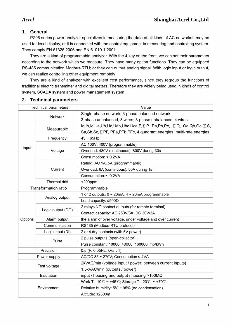
2. Technical parameters Technical parameters Value
Network Single-phase network; 3-phase balanced network 3-phase unbalanced, 3 wires; 3-phase unbalanced, 4 wires
Measurable Ia,Ib,Ic,Ua,Ub,Uc,Uab,Ubc,Uca,F,∑P, Pa,Pb,Pc, ∑Q, Qa,Qb,Qc,∑S, Sa,Sb,Sc,∑PF, PFa,PFb,PFc, 4 quadrant energies, multi-rate energies
Frequency 45 ~ 65Hz AC 100V, 400V (programmable) Overload: 480V (continuous); 800V during 30s Voltage Consumption: < 0.2VA Rating: AC 1A, 5A (programmable) Overload: 6A (continuous); 50A during 1s Current Consumption: < 0.2VA
Input
Thermal drift <200ppm Transformation ratio Programmable
1 or 2 outputs, 0 ~ 20mA, 4 ~ 20mA programmable Analog output
Load capacity: ≤500Ω 2 relays NO contact outputs (for remote terminal)
Logic output (DO) Contact capacity: AC 250V/3A, DC 30V/3A
Alarm output the alarm of over voltage, under voltage and over current Communication RS485 (Modbus-RTU protocol) Logic input (DI) 2 or 4 dry contacts (with 5V power)
2 pulse outputs (open-collector),
Options
Pulse Pulse constant: 10000, 40000, 160000 imp/kWh
Precision 0.5 (F: 0.05Hz; kVar: 1) Power supply AC/DC 85 ~ 270V; Consumption ≤ 4VA
2kVAC/min (voltage input / power; between current inputs) Test voltage
1.5kVAC/min (outputs / power) Insulation input / housing and output / housing >100MΩ
Work T: -10 ~ +45; Storage T: -20 ~ +70 Relative humidity: 5% ~ 95% (no condensation) Environment Altitude: ≤2500m
Acrel Shanghai Acrel Co.,Ltd
2
3. Installing and Wiring
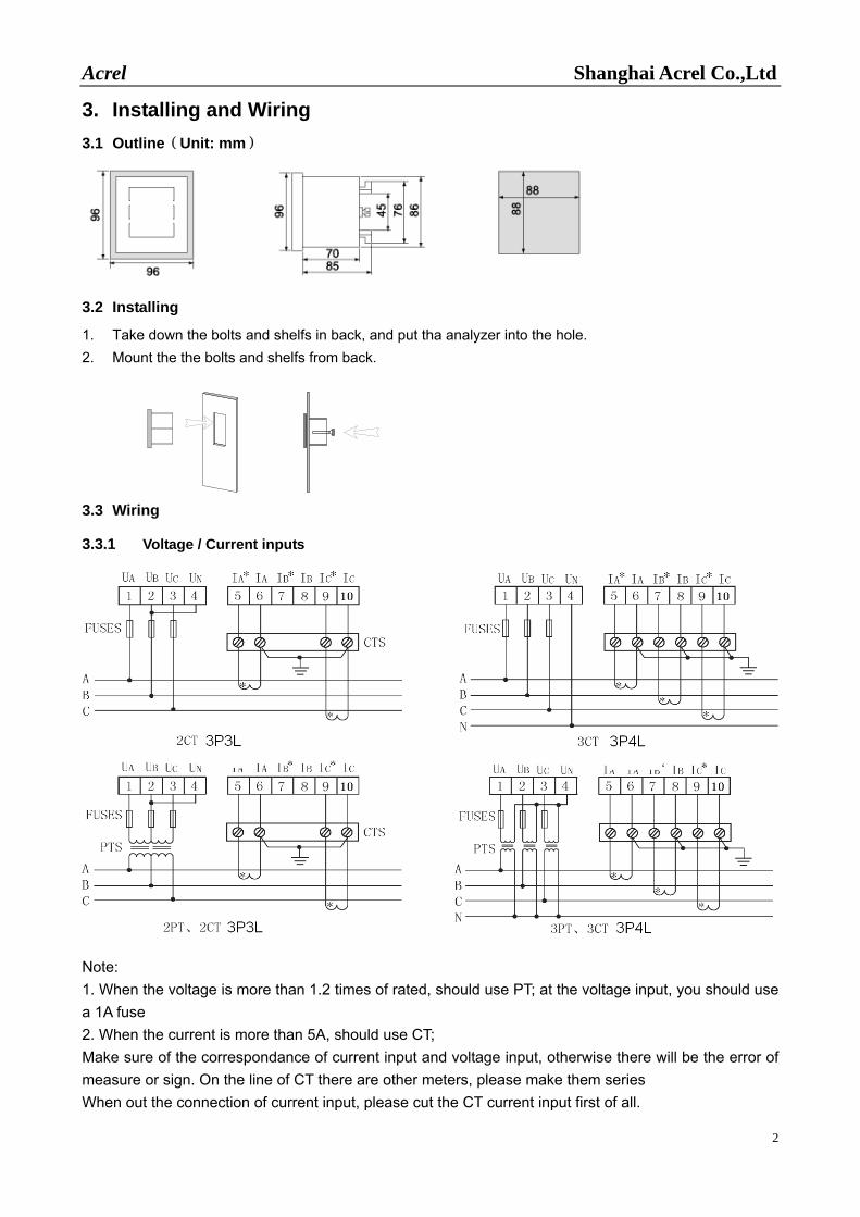
3.1 Outline(Unit: mm)
3.2 Installing
1. Take down the bolts and shelfs in back, and put tha analyzer into the hole. 2. Mount the the bolts and shelfs from back.
3.3 Wiring
3.3.1 Voltage / Current inputs
Note: 1. When the voltage is more than 1.2 times of rated, should use PT; at the voltage input, you should use a 1A fuse 2. When the current is more than 5A, should use CT; Make sure of the correspondance of current input and voltage input, otherwise there will be the error of measure or sign. On the line of CT there are other meters, please make them series When out the connection of current input, please cut the CT current input first of all.
Acrel Shanghai Acrel Co.,Ltd
3
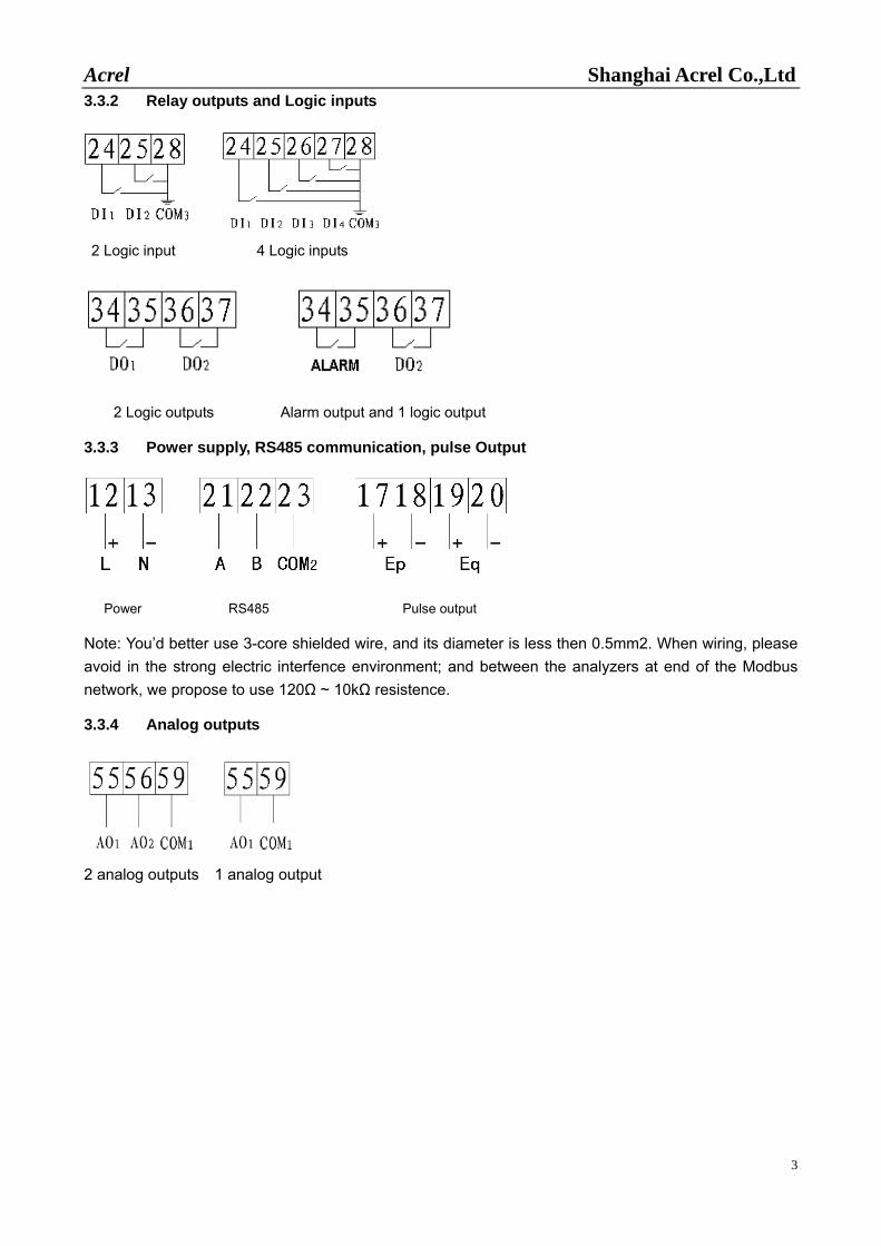
3.3.2 Relay outputs and Logic inputs
2 Logic input 4 Logic inputs
2 Logic outputs Alarm output and 1 logic output
3.3.3 Power supply, RS485 communication, pulse Output
Power RS485 Pulse output
Note: You’d better use 3-core shielded wire, and its diameter is less then 0.5mm2. When wiring, please avoid in the strong electric interfence environment; and between the analyzers at end of the Modbus network, we propose to use 120Ω ~ 10kΩ resistence.
3.3.4 Analog outputs
2 analog outputs 1 analog output
Acrel Shanghai Acrel Co.,Ltd
4
4. Reading and programming
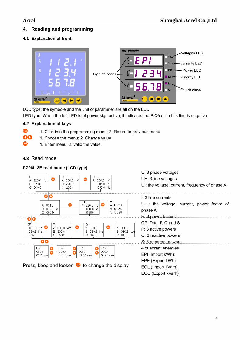
4.1 Explanation of front
LCD type: the symbole and the unit of parameter are all on the LCD. LED type: When the left LED is of power sign active, it indicates the P/Q/cos in this line is negative.
4.2 Explanation of keys
1. Click into the programming menu; 2. Return to previous menu 1. Choose the menu; 2. Change value
1. Enter menu; 2. valid the value
4.3 Read mode
PZ96L-3E read mode (LCD type)
Press, keep and loosen to change the display.
U: 3 phase voltages UH: 3 line voltages UI: the voltage, current, frequency of phase A I: 3 line currents UIH: the voltage, current, power factor of phase A H: 3 power factors QP: Total P, Q and S P: 3 active powers Q: 3 reactive powers S: 3 apparent powers 4 quadrant energies EPI (Import kWh); EPE (Export kWh) EQL (Import kVarh); EQC (Export kVarh)
Acrel Shanghai Acrel Co.,Ltd
5
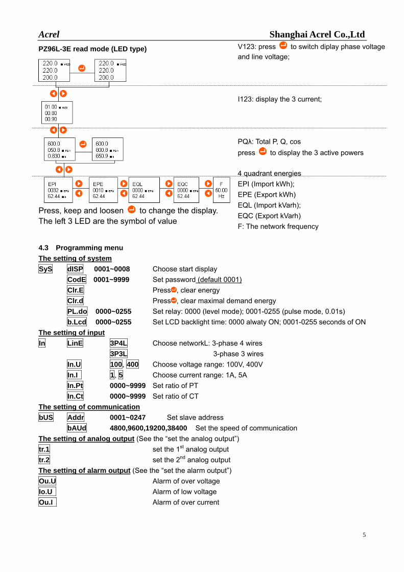
PZ96L-3E read mode (LED type)
Press, keep and loosen to change the display. The left 3 LED are the symbol of value
V123: press to switch diplay phase voltage and line voltage; I123: display the 3 current; PQλ: Total P, Q, cos press to display the 3 active powers 4 quadrant energies EPI (Import kWh); EPE (Export kWh) EQL (Import kVarh); EQC (Export kVarh) F: The network frequency
4.3 Programming menu The setting of system SyS dISP 0001~0008 Choose start display
CodE 0001~9999 Set password (default 0001) Clr.E Press , clear energy Clr.d Press , clear maximal demand energy
PL.do 0000~0255 Set relay: 0000 (level mode); 0001-0255 (pulse mode, 0.01s) b.Lcd 0000~0255 Set LCD backlight time: 0000 alwaty ON; 0001-0255 seconds of ON The setting of input In LinE 3P4L Choose networkL: 3-phase 4 wires 3P3L 3-phase 3 wires In.U 100, 400 Choose voltage range: 100V, 400V In.I 1, 5 Choose current range: 1A, 5A In.Pt 0000~9999 Set ratio of PT In.Ct 0000~9999 Set ratio of CT The setting of communication bUS Addr 0001~0247 Set slave address
bAUd 4800,9600,19200,38400 Set the speed of communication The setting of analog output (See the “set the analog output”) tr.1 set the 1st analog output tr.2 set the 2nd analog output The setting of alarm output (See the “set the alarm output”) Ou.U Alarm of over voltage Io.U Alarm of low voltage Ou.I Alarm of over current
Acrel Shanghai Acrel Co.,Ltd
6
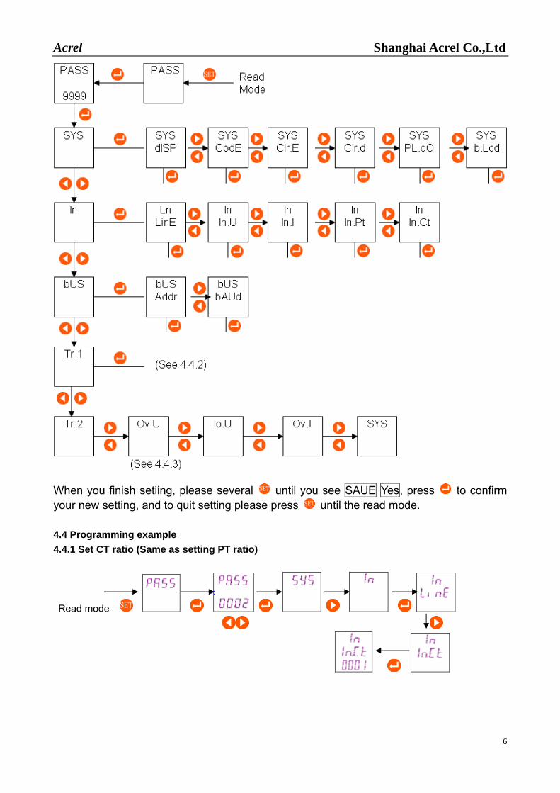
When you finish setiing, please several until you see SAUE Yes, press to confirm your new setting, and to quit setting please press until the read mode. 4.4 Programming example 4.4.1 Set CT ratio (Same as setting PT ratio)
Read mode
Acrel Shanghai Acrel Co.,Ltd
7
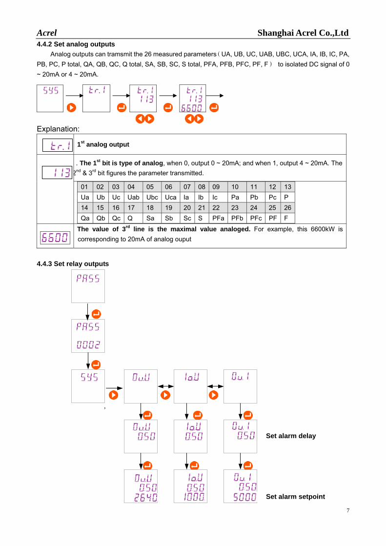
4.4.2 Set analog outputs Analog outputs can tramsmit the 26 measured parameters(UA, UB, UC, UAB, UBC, UCA, IA, IB, IC, PA,
PB, PC, P total, QA, QB, QC, Q total, SA, SB, SC, S total, PFA, PFB, PFC, PF, F) to isolated DC signal of 0 ~ 20mA or 4 ~ 20mA.
Explanation:
1st analog output
. The 1st bit is type of analog, when 0, output 0 ~ 20mA; and when 1, output 4 ~ 20mA. The 2nd & 3rd bit figures the parameter transmitted.
01 02 03 04 05 06 07 08 09 10 11 12 13 Ua Ub Uc Uab Ubc Uca Ia Ib Ic Pa Pb Pc P 14 15 16 17 18 19 20 21 22 23 24 25 26 Qa Qb Qc Q Sa Sb Sc S PFa PFb PFc PF F
The value of 3rd line is the maximal value analoged. For example, this 6600kW is corresponding to 20mA of analog ouput
4.4.3 Set relay outputs
Set alarm delay
Set alarm setpoint
,
Acrel Shanghai Acrel Co.,Ltd
8
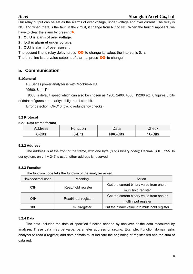
Our relay output can be set as the alarms of over voltage, under voltage and over current. The relay is NO, and when there is the fault in the circuit, it change from NO to NC. When the fault disappears, we have to clear the alarm by pressing . 1、Ou.U is alarm of over voltage. 2、lo.U is alarm of under voltage. 3、OU.I is alarm of over current. The second line is relay delay; press to change its value, the interval is 0.1s The third line is the value setpoint of alarms, press to change it.
5. Communication
5.1General PZ Series power analyzer is with Modbus-RTU. “9600, 8, n, 1” 9600 is default speed which can also be chosen as 1200, 2400, 4800, 19200 etc. 8 figures 8 bits
of data; n figures non- parity;1 figures 1 stop bit. Error detection: CRC16 (cyclic redundancy checks)
5.2 Protocol 5.2.1 Data frame format
Address Function Data Check 8-Bits 8-Bits N×8-Bits 16-Bits
5.2.2 Address
The address is at the front of the frame, with one byte (8 bits binary code); Decimal is 0 ~ 255. In our system, only 1 ~ 247 is used, other address is reserved. 5.2.3 Function
The function code tells the function of the analyzer asked.
Hexadecimal code Meaning Action
03H Read/hold register Get the current binary value from one or
multi hold register
04H Read/input register Get the current binary value from one or
multi input register 10H multiregister Put the binary value into multi hold register.
5.2.4 Data
The data includes the data of specified function needed by analyzer or the data measured by analyzer. These data may be value, parameter address or setting. Example: Function domain asks analyzer to read a register, and data domain must indicate the beginning of register red and the sum of data red.
Acrel Shanghai Acrel Co.,Ltd
9
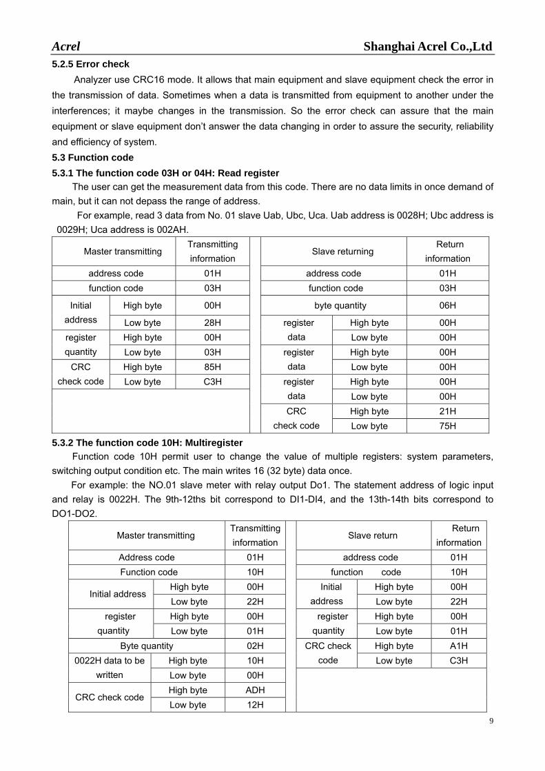
5.2.5 Error check Analyzer use CRC16 mode. It allows that main equipment and slave equipment check the error in
the transmission of data. Sometimes when a data is transmitted from equipment to another under the interferences; it maybe changes in the transmission. So the error check can assure that the main equipment or slave equipment don’t answer the data changing in order to assure the security, reliability and efficiency of system. 5.3 Function code 5.3.1 The function code 03H or 04H: Read register
The user can get the measurement data from this code. There are no data limits in once demand of main, but it can not depass the range of address.
For example, read 3 data from No. 01 slave Uab, Ubc, Uca. Uab address is 0028H; Ubc address is 0029H; Uca address is 002AH.
Master transmitting Transmitting information
Slave returning Return
information address code 01H address code 01H function code 03H function code 03H
High byte 00H byte quantity 06H Initial address Low byte 28H High byte 00H
High byte 00H register
data Low byte 00H register quantity Low byte 03H High byte 00H
High byte 85H register
data Low byte 00H CRC check code Low byte C3H High byte 00H register
data Low byte 00H High byte 21H CRC
check code Low byte 75H
5.3.2 The function code 10H: Multiregister Function code 10H permit user to change the value of multiple registers: system parameters,
switching output condition etc. The main writes 16 (32 byte) data once. For example: the NO.01 slave meter with relay output Do1. The statement address of logic input
and relay is 0022H. The 9th-12ths bit correspond to DI1-DI4, and the 13th-14th bits correspond to DO1-DO2.
Master transmitting Transmitting information
Slave return Return information
Address code 01H address code 01H Function code 10H function code 10H
High byte 00H High byte 00H Initial address
Low byte 22H Initial
address Low byte 22H High byte 00H High byte 00H register
quantity Low byte 01H register quantity Low byte 01H
Byte quantity 02H High byte A1H High byte 10H
CRC check code Low byte C3H 0022H data to be
written Low byte 00H High byte ADH
CRC check code Low byte 12H
Acrel Shanghai Acrel Co.,Ltd
10
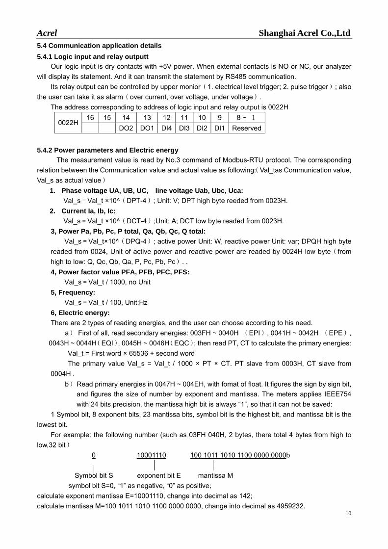
5.4 Communication application details 5.4.1 Logic input and relay outputt
Our logic input is dry contacts with +5V power. When external contacts is NO or NC, our analyzer will display its statement. And it can transmit the statement by RS485 communication.
Its relay output can be controlled by upper monior(1. electrical level trigger; 2. pulse trigger); also the user can take it as alarm(over current, over voltage, under voltage).
The address corresponding to address of logic input and relay output is 0022H 16 15 14 13 12 11 10 9 8 ~ 1
0022H DO2 DO1 DI4 DI3 DI2 DI1 Reserved
5.4.2 Power parameters and Electric energy
The measurement value is read by No.3 command of Modbus-RTU protocol. The corresponding relation between the Communication value and actual value as following:(Val_tas Communication value, Val_s as actual value)
1. Phase voltage UA, UB, UC, line voltage Uab, Ubc, Uca: Val_s=Val_t ×10^(DPT-4); Unit: V; DPT high byte reeded from 0023H.
2. Current Ia, Ib, Ic: Val_s=Val_t ×10^(DCT-4);Unit: A; DCT low byte readed from 0023H.
3, Power Pa, Pb, Pc, P total, Qa, Qb, Qc, Q total: Val_s=Val_t×10^(DPQ-4); active power Unit: W, reactive power Unit: var; DPQH high byte
readed from 0024, Unit of active power and reactive power are readed by 0024H low byte(from high to low: Q, Qc, Qb, Qa, P, Pc, Pb, Pc). . 4, Power factor value PFA, PFB, PFC, PFS: Val_s=Val_t / 1000, no Unit 5, Frequency: Val_s=Val_t / 100, Unit:Hz 6, Electric energy: There are 2 types of reading energies, and the user can choose according to his need.
a) First of all, read secondary energies: 003FH ~ 0040H (EPI), 0041H ~ 0042H (EPE), 0043H ~ 0044H(EQI), 0045H ~ 0046H(EQC); then read PT, CT to calculate the primary energies:
Val_t = First word × 65536 + second word The primary value Val_s = Val_t / 1000 × PT × CT. PT slave from 0003H, CT slave from
0004H . b) Read primary energies in 0047H ~ 004EH, with fomat of float. It figures the sign by sign bit,
and figures the size of number by exponent and mantissa. The meters applies IEEE754 with 24 bits precision, the mantissa high bit is always “1”, so that it can not be saved:
1 Symbol bit, 8 exponent bits, 23 mantissa bits, symbol bit is the highest bit, and mantissa bit is the lowest bit.
For example: the following number (such as 03FH 040H, 2 bytes, there total 4 bytes from high to low,32 bit)
0 10001110 100 1011 1010 1100 0000 0000b
Symbol bit S exponent bit E mantissa M symbol bit S=0, “1” as negative, “0” as positive;
calculate exponent mantissa E=10001110, change into decimal as 142; calculate mantissa M=100 1011 1010 1100 0000 0000, change into decimal as 4959232.
Acrel Shanghai Acrel Co.,Ltd
11
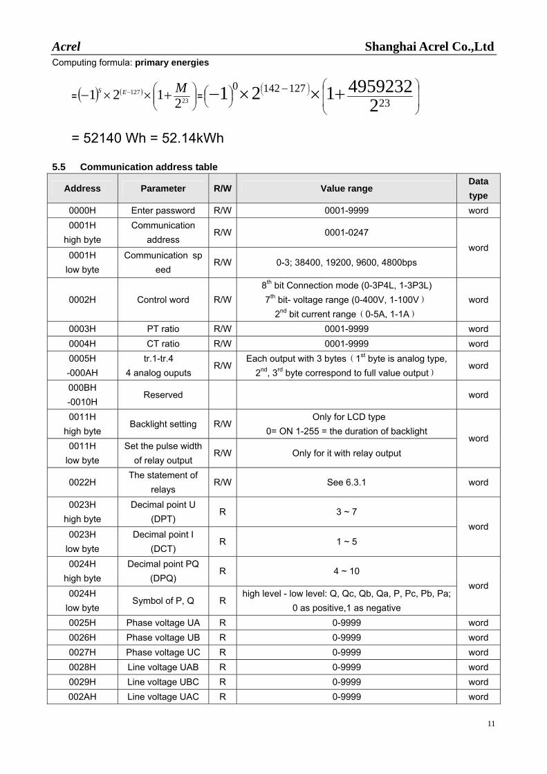
Computing formula: primary energies
= ( ) ( )⎟⎟⎠
⎞⎜⎜⎝
⎛ +××− −23
127
2121 MES= ⎟
⎟
⎠
⎞
⎜⎜
⎝
⎛−⎟⎠⎞⎜
⎝⎛ +××− ⎟
⎠⎞⎜
⎝⎛
231271420
24959232121
= 52140 Wh = 52.14kWh
5.5 Communication address table
Address Parameter R/W Value range Data type
0000H Enter password R/W 0001-9999 word 0001H
high byte Communication
address R/W 0001-0247
0001H low byte
Communication speed
R/W 0-3; 38400, 19200, 9600, 4800bps word
0002H Control word R/W8th bit Connection mode (0-3P4L, 1-3P3L) 7th bit- voltage range (0-400V, 1-100V)
2nd bit current range(0-5A, 1-1A) word
0003H PT ratio R/W 0001-9999 word 0004H CT ratio R/W 0001-9999 word 0005H -000AH
tr.1-tr.4 4 analog ouputs
R/WEach output with 3 bytes(1st byte is analog type,
2nd, 3rd byte correspond to full value output) word
000BH -0010H
Reserved word
0011H high byte
Backlight setting R/WOnly for LCD type
0= ON 1-255 = the duration of backlight 0011H
low byte Set the pulse width
of relay output R/W Only for it with relay output
word
0022H The statement of
relays R/W See 6.3.1 word
0023H high byte
Decimal point U (DPT)
R 3 ~ 7
0023H low byte
Decimal point I (DCT)
R 1 ~ 5 word
0024H high byte
Decimal point PQ (DPQ)
R 4 ~ 10
0024H low byte
Symbol of P, Q R high level - low level: Q, Qc, Qb, Qa, P, Pc, Pb, Pa;
0 as positive,1 as negative
word
0025H Phase voltage UA R 0-9999 word 0026H Phase voltage UB R 0-9999 word 0027H Phase voltage UC R 0-9999 word 0028H Line voltage UAB R 0-9999 word 0029H Line voltage UBC R 0-9999 word 002AH Line voltage UAC R 0-9999 word
Acrel Shanghai Acrel Co.,Ltd
12
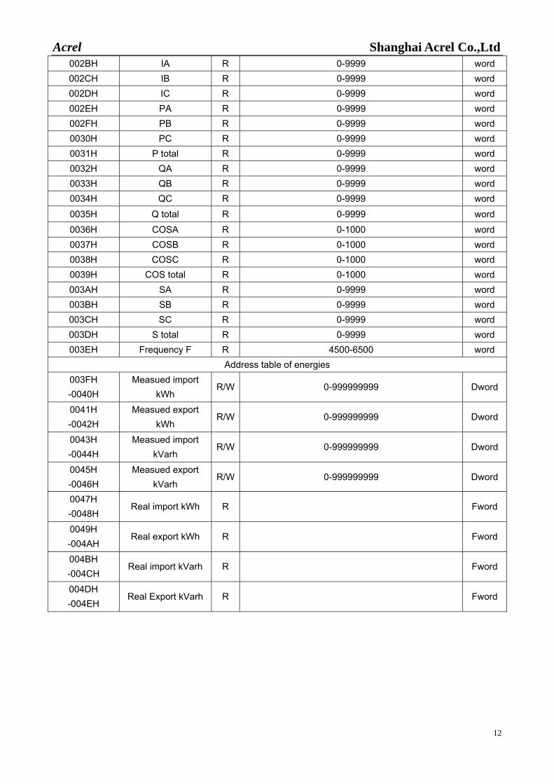
002BH IA R 0-9999 word 002CH IB R 0-9999 word 002DH IC R 0-9999 word 002EH PA R 0-9999 word 002FH PB R 0-9999 word 0030H PC R 0-9999 word 0031H P total R 0-9999 word 0032H QA R 0-9999 word 0033H QB R 0-9999 word 0034H QC R 0-9999 word
0035H Q total R 0-9999 word 0036H COSA R 0-1000 word 0037H COSB R 0-1000 word 0038H COSC R 0-1000 word 0039H COS total R 0-1000 word 003AH SA R 0-9999 word 003BH SB R 0-9999 word 003CH SC R 0-9999 word 003DH S total R 0-9999 word 003EH Frequency F R 4500-6500 word
Address table of energies 003FH -0040H
Measued import kWh
R/W 0-999999999 Dword
0041H -0042H
Measued export kWh
R/W 0-999999999 Dword
0043H -0044H
Measued import kVarh
R/W 0-999999999 Dword
0045H -0046H
Measued export kVarh
R/W 0-999999999 Dword
0047H -0048H
Real import kWh R Fword
0049H -004AH
Real export kWh R Fword
004BH -004CH
Real import kVarh R Fword
004DH -004EH
Real Export kVarh R Fword