Embed Size (px)
Citation preview

Heat Recovery Ventilation UnitProduct Manual
HRV10 Q Plus TP440A
TP440ABDTP440ABS
HRV10M Q Plus TP441A
TP441ABDTP441ABS
IMPORTANT - Fully read this Product Manual to help ensure the ventilation system is installed, commissioned and used properly.
ventilation systems
EN

User GuideHeat Recovery Ventilation System� � � � � � � � � � � � � � � 3
Ventilation is Vital � � � � � � � � � � � � � � � � � � � � � � � 4How the System Works � � � � � � � � � � � � � � � � � � � 4How to Use the System � � � � � � � � � � � � � � � � � � � 6Maintenance� � � � � � � � � � � � � � � � � � � � � � � � � � � � 6
Product OverviewSafety and Guidance � � � � � � � � � � � � � � � � � � � � � � � � � � 7Dimensions HRV10 Q Plus� � � � � � � � � � � � � � � � � �8Dimensions HRV10M Q Plus � � � � � � � � � � � � � � � �9Product Features � � � � � � � � � � � � � � � � � � � � � � � � � � � � 10Controls & Features � � � � � � � � � � � � � � � � � � � � � � � � � � 11
Setback Speed � � � � � � � � � � � � � � � � � � � � � � � � � 11Boost Speed with Overrun Timer � � � � � � � � � � 11SUMMERboost® � � � � � � � � � � � � � � � � � � � � � � � � 11Summer Bypass � � � � � � � � � � � � � � � � � � � � � � � � 12Automatic Frost Protection� � � � � � � � � � � � � � � 12Duct Heater� � � � � � � � � � � � � � � � � � � � � � � � � � � � 12Summer Mode � � � � � � � � � � � � � � � � � � � � � � � � � 12
Packaging Contents� � � � � � � � � � � � � � � � � � � � � � � � � � 13
InstallationFixing � � � � � � � � � � � � � � � � � � � � � � � � � � � � � � � � � � � � � 14Condensate Drain � � � � � � � � � � � � � � � � � � � � � � � � � � � 17
Fitting � � � � � � � � � � � � � � � � � � � � � � � � � � � � � � � � 17Ducting Connections � � � � � � � � � � � � � � � � � � � � � � � � � 19Wiring & Safety � � � � � � � � � � � � � � � � � � � � � � � � � � � � � 21Wiring Connections Access � � � � � � � � � � � � � � � � � � � � 21Wiring Diagrams � � � � � � � � � � � � � � � � � � � � � � � � � � � � 22Wiring Diagrams � � � � � � � � � � � � � � � � � � � � � � � � � � � � 23Wiring Diagrams � � � � � � � � � � � � � � � � � � � � � � � � � � � � 24Wiring Diagrams � � � � � � � � � � � � � � � � � � � � � � � � � � � � 25Duct Heater � � � � � � � � � � � � � � � � � � � � � � � � � � � � � � � � 26
Fitting � � � � � � � � � � � � � � � � � � � � � � � � � � � � � � � � 27Connection to Mains � � � � � � � � � � � � � � � � � � � � 28Maintenance� � � � � � � � � � � � � � � � � � � � � � � � � � � 29Overheating � � � � � � � � � � � � � � � � � � � � � � � � � � � 29
Controls� � � � � � � � � � � � � � � � � � � � � � � � � � � � � � � � � � � � 30Control Parameters � � � � � � � � � � � � � � � � � � � � � 30Continuous Supply & Extract Speeds� � � � � � � 31Boost Supply & Extract Speeds � � � � � � � � � � � 31Boost Overrun� � � � � � � � � � � � � � � � � � � � � � � � � � 31Controller Reset � � � � � � � � � � � � � � � � � � � � � � � � 32Hardware Reset � � � � � � � � � � � � � � � � � � � � � � � � 32
MaintenanceRoutine Maintenance � � � � � � � � � � � � � � � � � � � � � � � � 33
HRV 10 Q Plus Front Cover Removal � � � � � � � 33HRV 10M Q Plus Front Cover Removal � � � � � � 34Cleaning Interior � � � � � � � � � � � � � � � � � � � � � � � 34Cleaning Exterior � � � � � � � � � � � � � � � � � � � � � � � 34Filter Replacement� � � � � � � � � � � � � � � � � � � � � � 35
Service Record � � � � � � � � � � � � � � � � � � � � � � � � � � � � � � 37
2
User GuideHeat Recovery Ventilation System
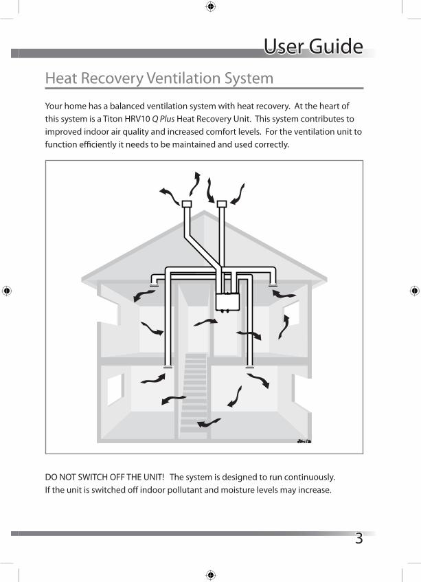
Your home has a balanced ventilation system with heat recovery. At the heart of this system is a Titon HRV10 Q Plus Heat Recovery Unit. This system contributes to improved indoor air quality and increased comfort levels. For the ventilation unit to function efficiently it needs to be maintained and used correctly.
DO NOT SWITCH OFF THE UNIT! The system is designed to run continuously. If the unit is switched off indoor pollutant and moisture levels may increase.
3
Ventilation is Vital
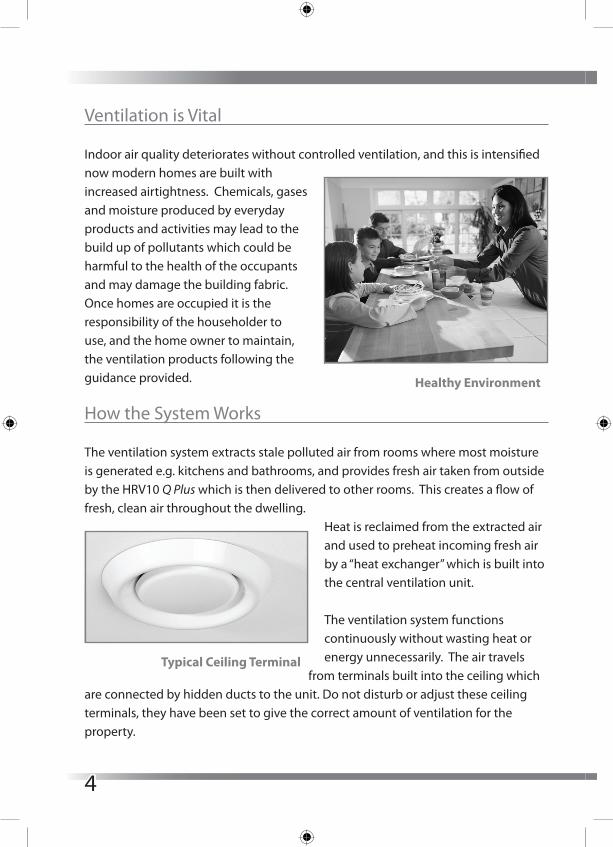
Indoor air quality deteriorates without controlled ventilation, and this is intensified now modern homes are built with increased airtightness. Chemicals, gases and moisture produced by everyday products and activities may lead to the build up of pollutants which could be harmful to the health of the occupants and may damage the building fabric.Once homes are occupied it is the responsibility of the householder to use, and the home owner to maintain, the ventilation products following the guidance provided.
How the System Works
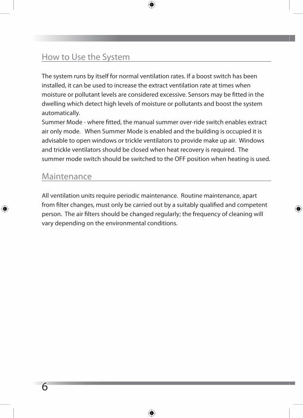
The ventilation system extracts stale polluted air from rooms where most moisture is generated e.g. kitchens and bathrooms, and provides fresh air taken from outside by the HRV10 Q Plus which is then delivered to other rooms. This creates a flow of fresh, clean air throughout the dwelling.
Heat is reclaimed from the extracted air and used to preheat incoming fresh air by a “heat exchanger” which is built into the central ventilation unit.
The ventilation system functions continuously without wasting heat or energy unnecessarily. The air travels
from terminals built into the ceiling which are connected by hidden ducts to the unit. Do not disturb or adjust these ceiling terminals, they have been set to give the correct amount of ventilation for the property.
Typical Ceiling Terminal
Healthy Environment
4

The central unit is usually installed in a roof space or cupboard although most of the system is hidden from view as it has been designed into the house construction. Most systems have a facility to boost the ventilation rate at times when more moisture is being generated, such as when bathing or cooking.During cold weather the frost protection program will automatically vary the ventilation to ensure that there is no build up of ice in the unit. During operation,
you may notice small changes in airflow or noise levels. This is quite normal as the unit is designed to operate in this way.
ExtractTerminalse.g. kitchen,bathrooms &toilets
Supply Terminalse.g. living room, dining room
& bedrooms
HRV Q Plus
Inlet
Exhaust
System Layout
5
How to Use the System
The system runs by itself for normal ventilation rates. If a boost switch has been installed, it can be used to increase the extract ventilation rate at times when moisture or pollutant levels are considered excessive. Sensors may be fitted in the dwelling which detect high levels of moisture or pollutants and boost the system automatically. Summer Mode - where fitted, the manual summer over-ride switch enables extract air only mode. When Summer Mode is enabled and the building is occupied it is advisable to open windows or trickle ventilators to provide make up air. Windows and trickle ventilators should be closed when heat recovery is required. The summer mode switch should be switched to the OFF position when heating is used.
Maintenance
All ventilation units require periodic maintenance. Routine maintenance, apart from filter changes, must only be carried out by a suitably qualified and competent person. The air filters should be changed regularly; the frequency of cleaning will vary depending on the environmental conditions.
6

Product OverviewSafety and Guidance
Important: read these instructions fully before the installation of this appliance 1. Installation of the appliance must be carried out by a qualified and suitable
competent person and be carried out in clean, dry conditions where dust and humidity are at minimal levels.
2. The unit must be stored in a clean and dry environment.3. Do not install the appliance in areas where the following may be present or
occur: - Excessive oil or a grease laden atmosphere. - Corrosive or flammable gases, liquids or vapours. - Ambient temperatures above 40°C or below -5°C. - Humidity levels above 90% or is a wet environment.
4. The appliance is not suitable for installation to the exterior of the dwelling.5. This appliance is not intended for use by persons (including children) with
reduced physical, sensory or mental capabilities, or lack of experience and knowledge, unless they have been given supervision or instruction concerning use of the appliance by a person responsible for their safety.
6. Children should be supervised to ensure that they do not play with the appliance.
7. Ensure that external grilles are located away from any flue outlet, in accordance with relevant Building Regulations.
8. The unit must not be connected to a tumble dryer.9. The unit must not be connected to a cooker hood.10. Precautions must be taken to avoid the back-flow of gases into the room from
an open flue appliance.11. Ensure all ducting and condensate drain and associated pipe work is free from
debris and blockages before switching on the unit.
7
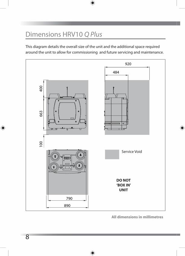
Dimensions HRV10 Q Plus
This diagram details the overall size of the unit and the additional space required around the unit to allow for commissioning and future servicing and maintenance.
Service Void
484
920
663
400
100
890
790
DO NOT‘BOX IN’
UNIT
All dimensions in millimetres
8

Dimensions HRV10M Q Plus
This diagram details the overall size of the unit and the additional space required around the unit to allow for commissioning and future servicing and maintenance.
All dimensions in millimetres
920
DO NOT‘BOX IN’
UNIT
Service Void
470
800900
100
400
675
9
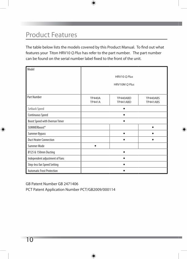
Product Features
The table below lists the models covered by this Product Manual. To find out what features your Titon HRV10 Q Plus has refer to the part number. The part number can be found on the serial number label fixed to the front of the unit.
Model
HRV10 Q Plus
HRV10M Q Plus
Part Number TP440ATP441A
TP440ABDTP441ABD
TP440ABSTP441ABS
Setback Speed l
Continuous Speed l
Boost Speed with Overrun Timer l
SUMMERboost® l
Summer Bypass l l
Duct Heater Connection l l
Summer Mode l
Ø125 & 150mm Ducting l
Independent adjustment of Fans l
Step-less fan Speed Setting l
Automatic Frost Protection l
GB Patent Number GB 2471406PCT Patent Application Number PCT/GB2009/000114
10

Controls & Features
The HRV10 Q Plus units are controllable by various volt free switches and sensors. The following describes the controls and features of the HRV10 Q Plus units and how they are controlled. Refer to the table opposite. Ensure all controls are adequately labelled, indicating their function clearly.
Setback SpeedSetback Speed is used to reduce ventilation rates. Setback Speed is automatically set at the mid point between minimum possible continuous speed and the selected continuous speed. The Setback Speed can be enabled by connection of a volt free one-way switch, or combined with the Boost Speed with the 3 position switch TP 508.
Boost Speed with Overrun TimerBoost Speed increases the extract and supply air flow. Boost Speed is configured with Step-less independent fan controls and includes an installer adjusted Overrun Timer variable between 0 and 60 minutes. The Boost Speed can be triggered by any device which provides a volt free one-way switch, such as a PIR, thermostat, humidistat or a standard one-way switch.
SUMMERboost®The SUMMERboost facility automatically configures both the supply fan and extract fan to run at full speed whenever the Summer Bypass activates. SUMMERboost® operation can be disabled manually or automatically. Manual - This is by means of a volt-free switch wired directly into the controller PCB Automatic - This is by means of a dedicated wall mounted room thermostat. In this configuration, the SUMMERboost® will only operate when the temperature within the room has exceeded the dedicated thermostat setting. Should the room temperature fall below the thermostat setting, then SUMMERboost® will not operate.
11

Summer BypassSummer Bypass is designed to operate during hot periods where fresh air can be vented straight into the property without being preheated by the extracted stale air. Summer Bypass operation is automatically controlled. The Summer Bypass mechanism diverts the stale air being extracted from the dwelling around the heat cell so that its heat energy is not transferred to the fresh air being supplied to the property.
Automatic Frost ProtectionDuring very cold weather, Automatic Frost Protection will detect temperatures that could form ice inside the unit. Automatic Frost Protection will reduce the supply ventilation rate to prevent ice build up within the heat cell. Automatic Frost Protection reduces the flow rate of cold air, thus allowing the warmer stale air to raise the temperature within the heat cell to such a level that prevents the formation of ice. As internal temperatures rise Automatic Frost Protection will increase the supply ventilation flow rate back to the commissioned settings.
Duct HeaterTo maintain ventilation flow rates where prolonged periods of very low temperatures occur, the facility for the control of a Duct Heater is provided, MAX 1000W. This is achieved using an electrically powered Duct Heater placed in-line between the outside supply vent and the From Atmosphere terminal on the HRV10 Q Plus. In these applications, the heater is used to pre-warm the outside fresh air supply before it enters the HRV10 Q Plus.
Summer ModeIn properties where it is desirable to reduce the supply of warm fresh air during hot weather, but where full Summer Bypass may be inappropriate or not available, the optional Summer Mode operation is available. Summer Mode operates by stopping the supply fan. Summer Mode can be triggered either manually or automatically:Manual - This is by means of a volt-free switch wired directly into the controller PCBAutomatic - This is by means of a dedicated wall mounted room thermostat. In this configuration Summer Mode will only operate when the temperature within the room has exceeded the dedicated thermostat setting. When Summer Mode is
12
selected the supply fan will remain off even if the HRV10 is placed into Boost.Summer Mode must not be installed in dwellings where open flue combustion appliances are used. Summer Mode must not be installed on HRV10 Q Plus ABD or HRV10 Q Plus ABS units.
Packaging Contents
Inspect the unit when taking delivery. Check the unit for damage and that all accessories have been supplied. Each HRV10 Q Plus unit is supplied with:
� Mounting Bracket x 1. � Ø40 x 12mm Condensate Drain worm gear hose clamp x 1. � Port Cover 150mm to 125 adapters x 4, supplied packed on Duct Ports. � Product Manual x 1. � User Guide x 1.
Any shortages or damage must be immediately reported to the supplier.
13

InstallationFixing
Titon recommend the use of guidance given in the Domestic Ventilation Compliance Guide 2010 Edition ISBN-978 1 85946 378 9 and Approved Document Part F 2010 ISBN-978 1 85946 370 3 for all installations in the United Kingdom.
The above documents can be downloaded free from www.planningportal.gov.uk.
Do not remove the Port Covers until connecting ducting. Port Covers are fitted to prevent debris falling into the unit and causing blockages and damage:
� The Titon HRV10 Q Plus is designed to be mounted on a wall or similar. The mounting surface must be sufficiently strong to support the unit.
� Consider the positioning of electrical services and the Condensate Drain when siting the unit.
� Ensure there is sufficient access around the HRV10 Q Plus for future maintenance.
� Do not ‘box-in’ the unit making access to the unit difficult for maintenance and repair.
14
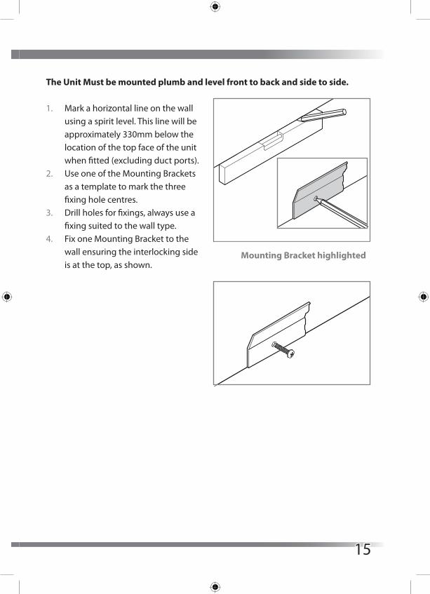
The Unit Must be mounted plumb and level front to back and side to side.
1. Mark a horizontal line on the wall using a spirit level. This line will be approximately 330mm below the location of the top face of the unit when fitted (excluding duct ports).
2. Use one of the Mounting Brackets as a template to mark the three fixing hole centres.
3. Drill holes for fixings, always use a fixing suited to the wall type.
4. Fix one Mounting Bracket to the wall ensuring the interlocking side is at the top, as shown.
Mounting Bracket highlighted
15
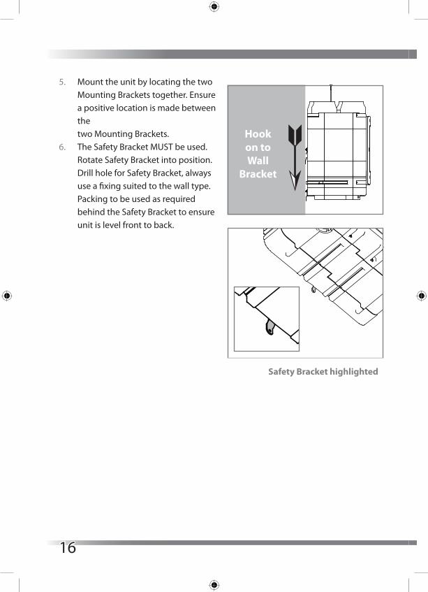
5. Mount the unit by locating the two Mounting Brackets together. Ensure a positive location is made between the two Mounting Brackets.
6. The Safety Bracket MUST be used. Rotate Safety Bracket into position. Drill hole for Safety Bracket, always use a fixing suited to the wall type. Packing to be used as required behind the Safety Bracket to ensure unit is level front to back.
Hookon toWall
Bracket
Safety Bracket highlighted
16

Condensate Drain
The unit’s Condensation Drain Pipe must be fitted and connected to the dwelling’s foul water drainage system in accordance with the relevant building regulations.
The Condensate Drain: � Is attached via the Condensation Drain Socket on the base of
the unit. � Must incorporate a suitable trap, which must act as an air lock. � Must be adequately secured and be insulated with the equivalent of at least
25mm of insulating material with a thermal conductivity of 0.04 W/(mK) if any part of the pipe passes though an unheated void.
� Should be installed to have a minimum 5° fall from the unit. � Titon recommend the use of a diaphragm type waste valve in place of a
conventional ‘wet’ trap which could dry out. Such as, BRE certificate no. 042/97 ‘Hepworth Hepv0 Hygienic self sealing plastic waste valve’ recommended as an alternative to traditional U-Traps.
17
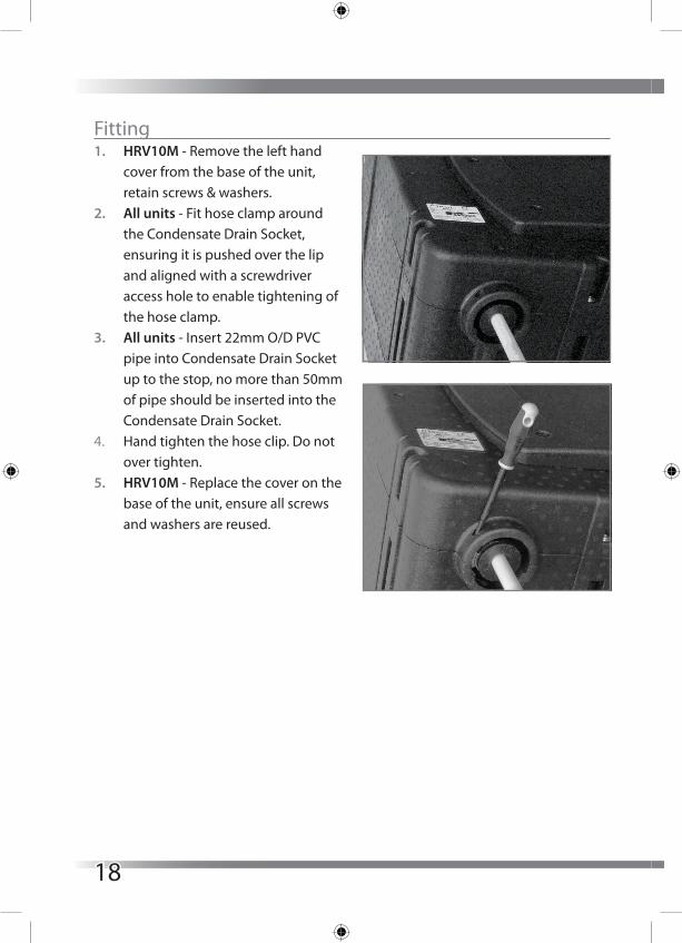
Fitting1. HRV10M - Remove the left hand
cover from the base of the unit, retain screws & washers.
2. All units - Fit hose clamp around the Condensate Drain Socket, ensuring it is pushed over the lip and aligned with a screwdriver access hole to enable tightening of the hose clamp.
3. All units - Insert 22mm O/D PVC pipe into Condensate Drain Socket up to the stop, no more than 50mm of pipe should be inserted into the Condensate Drain Socket.
4. Hand tighten the hose clip. Do not over tighten.
5. HRV10M - Replace the cover on the base of the unit, ensure all screws and washers are reused.
18

Ducting Connections
Titon recommend the use of guidance given in the Domestic Ventilation Compliance Guide 2010 Edition ISBN-978 1 85946 378 9 and Approved Document Part F 2010 ISBN-978 1 85946 370 3 for all installations in the United Kingdom.The above documents can be downloaded free from www.planningportal.gov.uk.
Once the unit has been installed and the ducting is ready to connect to the unit, remove the Port Covers from the Duct Ports.
Titon recommend:1. Ø150mm ducting is used to connect the HRV10 Q Plus� 2. A short piece of flexible ducting, approximately 200mm long is used to
connect the unit to the ducting system.3. Any flexible ducting used must be pulled taught.4. A minimum distance of 200mm between the HRV10 Q Plus unit and any sharp
bends in duct work.
ENSURE DUCTING IS CONNECTED TO THE CORRECT PORTS
Extract from dwelling
Supply to dwellingFrom atmosphere
To atmosphere
19
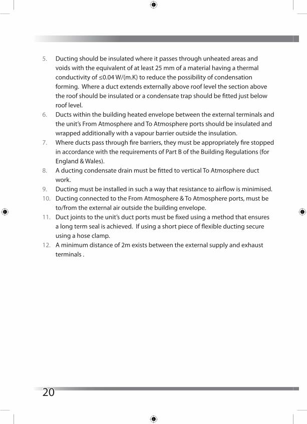
5. Ducting should be insulated where it passes through unheated areas and voids with the equivalent of at least 25 mm of a material having a thermal conductivity of ≤0.04 W/(m.K) to reduce the possibility of condensation forming. Where a duct extends externally above roof level the section above the roof should be insulated or a condensate trap should be fitted just below roof level.
6. Ducts within the building heated envelope between the external terminals and the unit’s From Atmosphere and To Atmosphere ports should be insulated and wrapped additionally with a vapour barrier outside the insulation.
7. Where ducts pass through fire barriers, they must be appropriately fire stopped in accordance with the requirements of Part B of the Building Regulations (for England & Wales).
8. A ducting condensate drain must be fitted to vertical To Atmosphere duct work.
9. Ducting must be installed in such a way that resistance to airflow is minimised.10. Ducting connected to the From Atmosphere & To Atmosphere ports, must be
to/from the external air outside the building envelope.11. Duct joints to the unit’s duct ports must be fixed using a method that ensures
a long term seal is achieved. If using a short piece of flexible ducting secure using a hose clamp.
12. A minimum distance of 2m exists between the external supply and exhaust terminals .
20

Wiring & Safety
WARNING: The unit MUST be earthed. All wiring must conform to current I.E.E. Wiring Regulations and all applicable standards and Building Regulations.
1. Electrical installation of the appliance MUST be carried out by a suitably qualified competent person.
2. The unit is supplied with a mains rated 3 core flexible cord (PVC sheathed, brown, blue and green/yellow 0.75mm²).
3. Inspect the appliance and electrical supply cord. If the supply cord is damaged, it must be replaced by the manufacturer, their service agent or similarly qualified persons in order to avoid a hazard.
4. The appliance must be connected to a local double pole isolation switch with a contact separation of at least 3mm.
5. HRV10 Q Plus is suitable for 230V ~ 50/60Hz single phase with a fuse rating of 3A.
6. Control cable access is via knockouts which are suitable for M12 or M16 cable glands. Ensure fitted cable glands maintain IP rating and provides strain relief.
7. Ensure all cable glands are fully tightened.
Wiring Connections Access
The electronics compartment is mounted on top of the unit. The compartment has two removable lids, front & rear. The front lid must always be removed before the rear lid; both lids are fixed by four screws. All wiring must be routed into the electronics compartment via the knock-outs and using cable glands or similar fitted to the rear lid.
Boost and other volt-free connections are on the MVHR controller PCB located at the front of the electronics compartment.
Duct heater connections are on the auxiliary PCB located at the rear of the electronics compartment
21
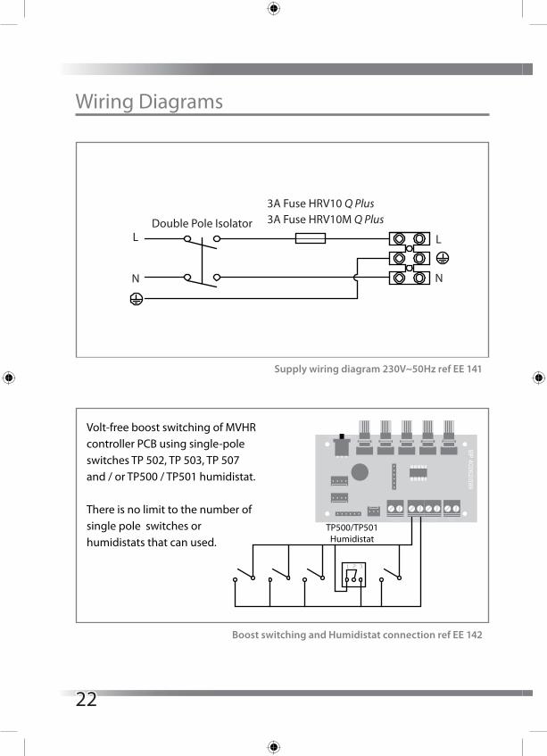
Wiring Diagrams
Double Pole Isolator 3A Fuse HRV10M Q Plus 3A Fuse HRV10 Q Plus
L
N
L
N
Supply wiring diagram 230V~50Hz ref EE 141
Volt-free boost switching of MVHR controller PCB using single-pole switches TP 502, TP 503, TP 507and / or TP500 / TP501 humidistat.
There is no limit to the number of single pole switches orhumidistats that can used.
SWITCH POSITIONS
1 - Setback Speed2 - Continous Speed3 - Boost Speed
Volt-free setback switching of MVHR controller PCB using single-pole latching switch and / or volt-free normally open relay contacts.
To avoid the unit being inadvertently left in Setback Mode, it is recom-mended that only one latching switch is �tted.
Volt-free disable of SUMMERboost® using one way latching switch.
ABS models only.
L U1 U2 U3
TP 508Three position rotary switch
Volt-free disable of SUMMERboost® using room thermostat.
ABS models only.
TP500/TP501Humidistat
1 2 3
Volt-free setback switch ornormally open relay contacts
BP 40262/099
Thermostat Switch
Boost Switch
Setback Switch
Input Temp
Boost Cont
TP 522
Latching SUMMERboost® switch
TP509 Room Thermostat
BP 40262/099
Thermostat Switch
Boost Switch
Setback Switch
Input Temp
Boost Cont
BP 40262/099
Thermostat Switch
Boost Switch
Setback Switch
Input Temp
Boost Cont
BP 40262/099
Thermostat Switch
Boost Switch
Setback Switch
Input Temp
Boost Cont
BP 40262/099
Thermostat Switch
Boost Switch
Setback Switch
Input Temp
Boost Cont
Y1
L
Y2
Volt-free activation of Summer Mode using one way latching switch.
Not to be installedon ABD & ABS models.
Volt-free activation of Summer Mode using room thermostat.
Not to be installedon ABD & ABS models.
TP 506Latching Summer Mode
switch
TP509Room Thermostat
BP 40262/099
Thermostat Switch
Boost Switch
Setback Switch
Input Temp
Boost Cont
BP 40262/099
Thermostat Switch
Boost Switch
Setback Switch
Input Temp
Boost Cont
Y1
L
Y2
Boost switching and Humidistat connection ref EE 142
22

Wiring Diagrams
Volt-free boost switching of MVHR controller PCB using single-pole switches TP 502, TP 503, TP 507and / or TP500 / TP501 humidistat.
There is no limit to the number of single pole switches orhumidistats that can used.
SWITCH POSITIONS
1 - Setback Speed2 - Continous Speed3 - Boost Speed
Volt-free setback switching of MVHR controller PCB using single-pole latching switch and / or volt-free normally open relay contacts.
To avoid the unit being inadvertently left in Setback Mode, it is recom-mended that only one latching switch is �tted.
Volt-free disable of SUMMERboost® using one way latching switch.
ABS models only.
L U1 U2 U3
TP 508Three position rotary switch
Volt-free disable of SUMMERboost® using room thermostat.
ABS models only.
TP500/TP501Humidistat
1 2 3
Volt-free setback switch ornormally open relay contacts
BP 40262/099
Thermostat Switch
Boost Switch
Setback Switch
Input Temp
Boost Cont
TP 522
Latching SUMMERboost® switch
TP509 Room Thermostat
BP 40262/099
Thermostat Switch
Boost Switch
Setback Switch
Input Temp
Boost Cont
BP 40262/099
Thermostat Switch
Boost Switch
Setback Switch
Input Temp
Boost Cont
BP 40262/099
Thermostat Switch
Boost Switch
Setback Switch
Input Temp
Boost Cont
BP 40262/099
Thermostat Switch
Boost Switch
Setback Switch
Input Temp
Boost Cont
Y1
L
Y2
Volt-free activation of Summer Mode using one way latching switch.
Not to be installedon ABD & ABS models.
Volt-free activation of Summer Mode using room thermostat.
Not to be installedon ABD & ABS models.
TP 506Latching Summer Mode
switch
TP509Room Thermostat
BP 40262/099
Thermostat Switch
Boost Switch
Setback Switch
Input Temp
Boost Cont
BP 40262/099
Thermostat Switch
Boost Switch
Setback Switch
Input Temp
Boost Cont
Y1
L
Y2
Summer Mode switch connection ref EE 144
Summer Mode thermostat connection ref EE 144
Volt-free boost switching of MVHR controller PCB using single-pole switches TP 502, TP 503, TP 507and / or TP500 / TP501 humidistat.
There is no limit to the number of single pole switches orhumidistats that can used.
SWITCH POSITIONS
1 - Setback Speed2 - Continous Speed3 - Boost Speed
Volt-free setback switching of MVHR controller PCB using single-pole latching switch and / or volt-free normally open relay contacts.
To avoid the unit being inadvertently left in Setback Mode, it is recom-mended that only one latching switch is �tted.
Volt-free disable of SUMMERboost® using one way latching switch.
ABS models only.
L U1 U2 U3
TP 508Three position rotary switch
Volt-free disable of SUMMERboost® using room thermostat.
ABS models only.
TP500/TP501Humidistat
1 2 3
Volt-free setback switch ornormally open relay contacts
BP 40262/099
Thermostat Switch
Boost Switch
Setback Switch
Input Temp
Boost Cont
TP 522
Latching SUMMERboost® switch
TP509 Room Thermostat
BP 40262/099
Thermostat Switch
Boost Switch
Setback Switch
Input Temp
Boost Cont
BP 40262/099
Thermostat Switch
Boost Switch
Setback Switch
Input Temp
Boost Cont
BP 40262/099
Thermostat Switch
Boost Switch
Setback Switch
Input Temp
Boost Cont
BP 40262/099
Thermostat Switch
Boost Switch
Setback Switch
Input Temp
Boost Cont
Y1
L
Y2
Volt-free activation of Summer Mode using one way latching switch.
Not to be installedon ABD & ABS models.
Volt-free activation of Summer Mode using room thermostat.
Not to be installedon ABD & ABS models.
TP 506Latching Summer Mode
switch
TP509Room Thermostat
BP 40262/099
Thermostat Switch
Boost Switch
Setback Switch
Input Temp
Boost Cont
BP 40262/099
Thermostat Switch
Boost Switch
Setback Switch
Input Temp
Boost Cont
Y1
L
Y2
23
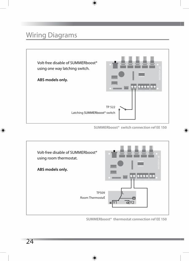
Wiring Diagrams
Volt-free boost switching of MVHR controller PCB using single-pole switches TP 502, TP 503, TP 507and / or TP500 / TP501 humidistat.
There is no limit to the number of single pole switches orhumidistats that can used.
SWITCH POSITIONS
1 - Setback Speed2 - Continous Speed3 - Boost Speed
Volt-free setback switching of MVHR controller PCB using single-pole latching switch and / or volt-free normally open relay contacts.
To avoid the unit being inadvertently left in Setback Mode, it is recom-mended that only one latching switch is �tted.
Volt-free disable of SUMMERboost® using one way latching switch.
ABS models only.
L U1 U2 U3
TP 508Three position rotary switch
Volt-free disable of SUMMERboost® using room thermostat.
ABS models only.
TP500/TP501Humidistat
1 2 3
Volt-free setback switch ornormally open relay contacts
BP 40262/099
Thermostat Switch
Boost Switch
Setback Switch
Input Temp
Boost Cont
TP 522
Latching SUMMERboost® switch
TP509 Room Thermostat
BP 40262/099
Thermostat Switch
Boost Switch
Setback Switch
Input Temp
Boost Cont
BP 40262/099
Thermostat Switch
Boost Switch
Setback Switch
Input Temp
Boost Cont
BP 40262/099
Thermostat Switch
Boost Switch
Setback Switch
Input Temp
Boost Cont
BP 40262/099
Thermostat Switch
Boost Switch
Setback Switch
Input Temp
Boost Cont
Y1
L
Y2
Volt-free activation of Summer Mode using one way latching switch.
Not to be installedon ABD & ABS models.
Volt-free activation of Summer Mode using room thermostat.
Not to be installedon ABD & ABS models.
TP 506Latching Summer Mode
switch
TP509Room Thermostat
BP 40262/099
Thermostat Switch
Boost Switch
Setback Switch
Input Temp
Boost Cont
BP 40262/099
Thermostat Switch
Boost Switch
Setback Switch
Input Temp
Boost Cont
Y1
L
Y2
SUMMERboost® switch connection ref EE 150
SUMMERboost® thermostat connection ref EE 150
Volt-free boost switching of MVHR controller PCB using single-pole switches TP 502, TP 503, TP 507and / or TP500 / TP501 humidistat.
There is no limit to the number of single pole switches orhumidistats that can used.
SWITCH POSITIONS
1 - Setback Speed2 - Continous Speed3 - Boost Speed
Volt-free setback switching of MVHR controller PCB using single-pole latching switch and / or volt-free normally open relay contacts.
To avoid the unit being inadvertently left in Setback Mode, it is recom-mended that only one latching switch is �tted.
Volt-free disable of SUMMERboost® using one way latching switch.
ABS models only.
L U1 U2 U3
TP 508Three position rotary switch
Volt-free disable of SUMMERboost® using room thermostat.
ABS models only.
TP500/TP501Humidistat
1 2 3
Volt-free setback switch ornormally open relay contacts
BP 40262/099
Thermostat Switch
Boost Switch
Setback Switch
Input Temp
Boost Cont
TP 522
Latching SUMMERboost® switch
TP509 Room Thermostat
BP 40262/099
Thermostat Switch
Boost Switch
Setback Switch
Input Temp
Boost Cont
BP 40262/099
Thermostat Switch
Boost Switch
Setback Switch
Input Temp
Boost Cont
BP 40262/099
Thermostat Switch
Boost Switch
Setback Switch
Input Temp
Boost Cont
BP 40262/099
Thermostat Switch
Boost Switch
Setback Switch
Input Temp
Boost Cont
Y1
L
Y2
Volt-free activation of Summer Mode using one way latching switch.
Not to be installedon ABD & ABS models.
Volt-free activation of Summer Mode using room thermostat.
Not to be installedon ABD & ABS models.
TP 506Latching Summer Mode
switch
TP509Room Thermostat
BP 40262/099
Thermostat Switch
Boost Switch
Setback Switch
Input Temp
Boost Cont
BP 40262/099
Thermostat Switch
Boost Switch
Setback Switch
Input Temp
Boost Cont
Y1
L
Y2
24

Wiring Diagrams
Volt-free boost switching of MVHR controller PCB using single-pole switches TP 502, TP 503, TP 507and / or TP500 / TP501 humidistat.
There is no limit to the number of single pole switches orhumidistats that can used.
SWITCH POSITIONS
1 - Setback Speed2 - Continous Speed3 - Boost Speed
Volt-free setback switching of MVHR controller PCB using single-pole latching switch and / or volt-free normally open relay contacts.
To avoid the unit being inadvertently left in Setback Mode, it is recom-mended that only one latching switch is �tted.
Volt-free disable of SUMMERboost® using one way latching switch.
ABS models only.
L U1 U2 U3
TP 508Three position rotary switch
Volt-free disable of SUMMERboost® using room thermostat.
ABS models only.
TP500/TP501Humidistat
1 2 3
Volt-free setback switch ornormally open relay contacts
BP 40262/099
Thermostat Switch
Boost Switch
Setback Switch
Input Temp
Boost Cont
TP 522
Latching SUMMERboost® switch
TP509 Room Thermostat
BP 40262/099
Thermostat Switch
Boost Switch
Setback Switch
Input Temp
Boost Cont
BP 40262/099
Thermostat Switch
Boost Switch
Setback Switch
Input Temp
Boost Cont
BP 40262/099
Thermostat Switch
Boost Switch
Setback Switch
Input Temp
Boost Cont
BP 40262/099
Thermostat Switch
Boost Switch
Setback Switch
Input Temp
Boost Cont
Y1
L
Y2
Volt-free activation of Summer Mode using one way latching switch.
Not to be installedon ABD & ABS models.
Volt-free activation of Summer Mode using room thermostat.
Not to be installedon ABD & ABS models.
TP 506Latching Summer Mode
switch
TP509Room Thermostat
BP 40262/099
Thermostat Switch
Boost Switch
Setback Switch
Input Temp
Boost Cont
BP 40262/099
Thermostat Switch
Boost Switch
Setback Switch
Input Temp
Boost Cont
Y1
L
Y2
Setback Mode switching and connection ref EE 143
Volt-free boost switching of MVHR controller PCB using single-pole switches TP 502, TP 503, TP 507and / or TP500 / TP501 humidistat.
There is no limit to the number of single pole switches orhumidistats that can used.
SWITCH POSITIONS
1 - Setback Speed2 - Continous Speed3 - Boost Speed
Volt-free setback switching of MVHR controller PCB using single-pole latching switch and / or volt-free normally open relay contacts.
To avoid the unit being inadvertently left in Setback Mode, it is recom-mended that only one latching switch is �tted.
Volt-free disable of SUMMERboost® using one way latching switch.
ABS models only.
L U1 U2 U3
TP 508Three position rotary switch
Volt-free disable of SUMMERboost® using room thermostat.
ABS models only.
TP500/TP501Humidistat
1 2 3
Volt-free setback switch ornormally open relay contacts
BP 40262/099
Thermostat Switch
Boost Switch
Setback Switch
Input Temp
Boost Cont
TP 522
Latching SUMMERboost® switch
TP509 Room Thermostat
BP 40262/099
Thermostat Switch
Boost Switch
Setback Switch
Input Temp
Boost Cont
BP 40262/099
Thermostat Switch
Boost Switch
Setback Switch
Input Temp
Boost Cont
BP 40262/099
Thermostat Switch
Boost Switch
Setback Switch
Input Temp
Boost Cont
BP 40262/099
Thermostat Switch
Boost Switch
Setback Switch
Input Temp
Boost Cont
Y1
L
Y2
Volt-free activation of Summer Mode using one way latching switch.
Not to be installedon ABD & ABS models.
Volt-free activation of Summer Mode using room thermostat.
Not to be installedon ABD & ABS models.
TP 506Latching Summer Mode
switch
TP509Room Thermostat
BP 40262/099
Thermostat Switch
Boost Switch
Setback Switch
Input Temp
Boost Cont
BP 40262/099
Thermostat Switch
Boost Switch
Setback Switch
Input Temp
Boost Cont
Y1
L
Y2
Three Position Rotary Switch TP 508 switching and connection ref EE 147
25
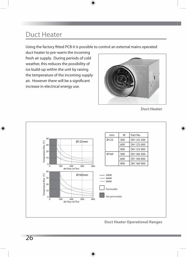
Duct Heater
Using the factory fitted PCB it is possible to control an external mains operated duct heater to pre-warm the incoming fresh air supply. During periods of cold weather, this reduces the possibility of ice build-up within the unit by raising the temperature of the incoming supply air. However there will be a significant increase in electrical energy use.
Duct Heater
Duct Heater Operational Ranges
300W600W900W
Permissible
Not permissible
Ø125mm
0
10
20
30
40
0 100 200 300 400Air Flow (m³/hr)
0 100 200 300 400Air Flow (m³/hr)
Tem
pera
ture
Ris
e (°
C)
Ø160mm
0
10
20
30
40
Tem
pera
ture
Ris
e (°
C)
mm W Part No.
Ø125 300 DH 125 300
600 DH 125 600
900 DH 125 900
Ø160 300 DH 160 300
600 DH 160 600
900 DH 160 900
26
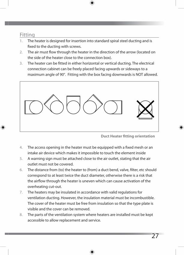
Fitting1. The heater is designed for insertion into standard spiral steel ducting and is
fixed to the ducting with screws.2. The air must flow through the heater in the direction of the arrow (located on
the side of the heater close to the connection box).3. The heater can be fitted in either horizontal or vertical ducting. The electrical
connection cabinet can be freely placed facing upwards or sideways to a maximum angle of 90°. Fitting with the box facing downwards is NOT allowed.
4. The access opening in the heater must be equipped with a fixed mesh or an intake air device which makes it impossible to touch the element inside
5. A warning sign must be attached close to the air outlet, stating that the air outlet must not be covered.
6. The distance from (to) the heater to (from) a duct bend, valve, filter, etc should correspond to at least twice the duct diameter, otherwise there is a risk that the airflow through the heater is uneven which can cause activation of the overheating cut-out.
7. The heaters may be insulated in accordance with valid regulations for ventilation ducting. However, the insulation material must be incombustible. The cover of the heater must be free from insulation so that the type plate is visible and the cover can be removed.
8. The parts of the ventilation system where heaters are installed must be kept accessible to allow replacement and service.
Duct Heater fitting orientation
27
9. The distance from the heater’s metal casing to any wood or other combustible material must NOT be less than 30 mm.
10. The maximum ambient temperature allowed is 40°C.11. The air flow through the heater must have a speed of at least 1.5 m/s.12. The maximum output temperature allowed is 40°C.
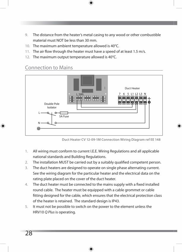
Connection to Mains
1. All wiring must conform to current I.E.E. Wiring Regulations and all applicable national standards and Building Regulations.
2. The installation MUST be carried out by a suitably qualified competent person.3. The duct heaters are designed to operate on single phase alternating current.
See the wiring diagram for the particular heater and the electrical data on the rating plate placed on the cover of the duct heater.
4. The duct heater must be connected to the mains supply with a fixed installed round cable. The heater must be equipped with a cable grommet or cable fitting designed for the cable, which ensures that the electrical protection class of the heater is retained. The standard design is IP43.
5. It must not be possible to switch on the power to the element unless the HRV10 Q Plus is operating.
Duct Heater CV 12-09-1M Connection Wiring Diagram ref EE 148
7 6 5 L1 L2 L3 N
Double PoleIsolator
5A FuseL
N
L SWL
Duct Heater
28

6. An all phase breaker or a double pole switch with a contact gap of at least 3mm must be included in the fixed installation.
7. The duct heater is equipped with two overheating cut-outs (one with manual reset) designed to prevent overheating when the airflow is too low or in the event of a fault in the system.
8. A drawing must be attached inside the fuse box or on the wall of the service room. The drawing shows the rating of the duct heaters and their location in the building, together with information about the measures to be taken in the event that the overheat protection cutout(s) is activated.
MaintenanceNo maintenance is required except a periodic functional test.
OverheatingWhen the overheating cut-out with manual reset has been activated, the following should be observed:
1. The heater must not be interfered with in any way, such as removal of the cover, except by an authorised electrical fitter.
2. Turn off the mains power.3. Investigate carefully the reason for activation of the cut-out.4. When the fault has been eliminated, the cut-out can be reset.
The heater has a built in manual reset thermal protection with the reset button placed on the lid of the duct heater.
29
Controls
The fan speeds of the Titon HRV10 Q Plus will require adjustment to ensure the flow rates achieved provide adequate ventilation. The Titon HRV10 Q Plus has 3 standard fan speed settings, Continuous Speed, Boost Speed and Setback Speed.
The Continuous Speed and Boost Speeds are adjustable via Rotary Potentiometers.Setback Speed is automatically set at the mid point between minimum possibleContinuous Speed and the selected Continuous Speed.
Prior to the first commission, set Continuous Speed potentiometers to minimum and Boost Speed potentiometers to maximum.
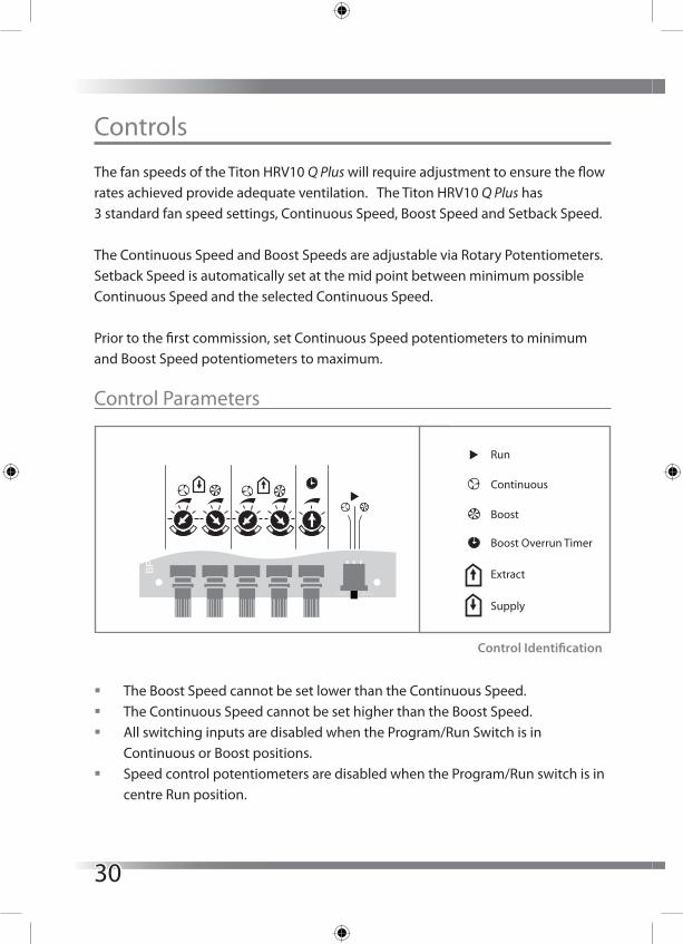
Control Parameters
� The Boost Speed cannot be set lower than the Continuous Speed. � The Continuous Speed cannot be set higher than the Boost Speed. � All switching inputs are disabled when the Program/Run Switch is in
Continuous or Boost positions. � Speed control potentiometers are disabled when the Program/Run switch is in
centre Run position.
Run
Continuous
Boost
Boost Overrun Timer
Extract
Supply
BP
4026
2/09
9
BoostCont
1
2
34 5
6
7
80 60
30
Control Identification
Run
Continuous
Boost
Boost Overrun Timer
Extract
Supply
BP
4026
2/09
9
BoostCont
1
2
34 5
6
7
80 60
30
30
For the commissioning settings to be stored the unit needs to be powered up.
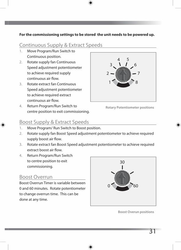
Continuous Supply & Extract Speeds1. Move Program/Run Switch to
Continuous position.2. Rotate supply fan Continuous
Speed adjustment potentiometer to achieve required supply continuous air flow.
3. Rotate extract fan Continuous Speed adjustment potentiometer to achieve required extract continuous air flow.
4. Return Program/Run Switch to centre position to exit commissioning.
Boost Supply & Extract Speeds1. Move Program/ Run Switch to Boost position.2. Rotate supply fan Boost Speed adjustment potentiometer to achieve required
supply boost air flow.3. Rotate extract fan Boost Speed adjustment potentiometer to achieve required
extract boost air flow.4. Return Program/Run Switch
to centre position to exit commissioning.
Boost OverrunBoost Overrun Timer is variable between 0 and 60 minutes. Rotate potentiometer to change overrun time. This can be done at any time.
Run
Continuous
Boost
Boost Overrun Timer
Extract
Supply
BP
4026
2/09
9
BoostCont
1
2
34 5
6
7
80 60
30
Rotary Potentiometer positions
Run
Continuous
Boost
Boost Overrun Timer
Extract
Supply
BP
4026
2/09
9
BoostCont
1
2
34 5
6
7
80 60
30
Boost Overun positions
31

Controller ResetFollowing a controller reset the ventilation system will need to be fully commissioned.
The procedure to reset the Titon HRV10 Q Plus controller is a simple three step operation. The unit will need to be powered up during the reset procedure.1. Rotate the Supply and Extract Continuous Speed potentiometers fully anti-
clockwise.2. Rotate Supply and Extract Boost Speed potentiometers fully clockwise.3. Move the Run/Program Switch from the Run position to the Continuous
position, from the Continuous position to the Boost position and back to the Run position. To ensure that the reset switch movements are registered by the controller wait two seconds between each switch movement.
Controller reset is now complete.
Hardware ResetCertain conditions (repeated supply interruptions etc.) can activate the automaticmotor protection mode. Whereby the fan motors are prevented from operating.This requires a hardware reset to return the unit to normal operating mode, to achieve this power to the unit should be switched off for 5 minutes, restoring the power after this time will reset the hardware of both the motor and PCB. Commissioning settings are not affected during a hardware reset.
32

MaintenanceRoutine Maintenance
All ventilation units require periodic maintenance. Routine maintenance, apart from filter changes, must only be carried out by a suitably qualified and competent person. The air filters should be checked regularly, the frequency of replacement will vary depending on the environmental conditions.
WARNING: The unit uses a 230V ~ supply and contains rotating mechanical parts. ISOLATE the unit from mains power supply and allow sufficient time for all moving parts to stop before undergoing any Servicing or Maintenance. The unit may be supplied with multiple live supply if a Duct Heater is fitted.
HRV 10 Q Plus Front Cover Removal1. ISOLATE the unit from mains power supply and allow sufficient time for all
moving parts to stop.2. Loosen the six screws located in the
front of the Cover.3. Completely remove the Front Cover
by pulling it away from the unit.
Front Cover replacement is the reverse of the above steps. Ensure that the large washers are re-used.
Note the two centre screws are shorter than the four corner screws. When refitting Front Cover do not overtighten screws.
33

HRV 10M Q Plus Front Cover Removal1. ISOLATE the unit from mains power supply and allow sufficient time for all
moving parts to stop.2. Loosen the six screws located in
the front of the Cover.3. Completely remove the Front
Cover by pulling it away from the unit.
4. Front Cover replacement is the reverse of the above steps. Ensure that the star washers are re-used.
Note the two centre screws are shorter than the four corner screws. When refitting Front Cover do not overtighten screws.
Cleaning InteriorFor best results:5. Slide out Filters fitted either side of heat exchanger.6. Carefully remove any dust from face of heat exchanger, interior of the unit and
the Bypass(if fitted) using a vacuum cleaner.7. Do not use water or any other fluids.
Cleaning ExteriorFor best results use a clean cloth and warm water with a mild detergent solution. Do not use solvents or abrasive cleaners.
34

Filter Replacement1. Remove Front Cover.2. Slide out Filters fitted either side of heat exchanger as shown.3. Replace Filters by carefully sliding the replacement Filters either side of the
heat exchanger.4. Ensure arrows printed on the ends of the Filters point towards the heat
exchanger.ABD and ABS models use unequal length Filters. When replacing Filters ensure the short filter is fitted to the right hand side of the heat exchanger, see illustration.
35

Replace the front cover. When refitting Front Cover do not overtighten screws.
Filters should be replaced at least annually, or more regularly dependent on environmental conditions. Replacement Filters are available from Titon.
Titon HRV10 Q Plus & HRV10M Q Plus Filters are available in grade G4.
Filter Part numbers in table below. The Unit part number can be found on the serial number label fixed to the front bottom left of the unit.
Model G4 Filters Set
HRV10 Q Plus TP440AHRV10M Q Plus TP441A
XP44022/099
HRV10 Q Plus TP440ABD HRV10M Q Plus TP440ABD
XP44023/099
HRV10 Q Plus TP440ABS HRV10M Q Plus TP440ABS
XP44023/099
36

Service Record
Serviced By Company Date Notes
37
We declare that the equipment detailed below conforms to the requirements of EC council directives relating to electromagnetic compatibility and safety of electrical equipment.
Equipment type: HRV10 Q Plus TP440A, TP440ABD, TP440ABS
Description of equipment: Mechanical ventilation unitRelevant EC Council Directives: 2006/95/EC (LVD), 2004/108/EC (EMC)Applied Harmonised Standards: BS EN 60335-1:2002+A2:2006 BS EN 60335-2-80:2003+A2:2009
Manufacturer: Titon Hardware Limited
Signature of manufacturer representatives
N C Howlett Development and Sustainability Director
P S Cowell BEng (Hons) CEng MCIBSE Research and Development Manager
K Tabron Production Director
International House, Peartree Road, Stanway, Colchester, Essex CO3 0JL
14 June 2012
14 June 2012
14 June 2012
38

We declare that the equipment detailed below conforms to the requirements of EC council directives relating to electromagnetic compatibility and safety of electrical equipment.
Equipment type: HRV10M Q Plus TP441A, TP441ABD, TP441ABS
Description of equipment: Mechanical ventilation unitRelevant EC Council Directives: 2006/95/EC (LVD), 2004/108/EC (EMC)Applied Harmonised Standards: BS EN 60335-1:2002+A2:2006 BS EN 60335-2-80:2003+A2:2009
Manufacturer: Titon Hardware Limited
Signature of manufacturer representatives
N C Howlett Development and Sustainability Director
P S Cowell BEng (Hons) CEng MCIBSE Research and Development Manager
K Tabron Production Director
International House, Peartree Road, Stanway, Colchester, Essex CO3 0JL
14 September 2012
14 September 2012
14 September 2012
39

Installed by:
MARKETING DIVISIONInternational House, Peartree Road, Stanway, Colchester, Essex CO3 0JLTel: +44 (0) 1206 713800 Fax: +44 (0) 1206 543126Email: [email protected] Web: www.titon.com
©2012TITON DO 4938 iss03
In the event of any queries please contact the system
installer.
Ensure this booklet is passed to the householder once
installation & commissioning of the ventilation system
is complete. This Product Manual must be kept in the
Home Information Pack and used as a service record.