Embed Size (px)
Citation preview

O W N E R ’ S M A N U A L
Q 4 3 1 F X3 1- B a n d G r a p h i c E q u a l i z e r w i t h F L S
C o n s t a n t Q F i l t e r s
™
®
2
Intended to alert the user to the presence of uninsulated "dangerous voltage" within the product's enclosurethat may be of sufficient magnitude to constitute a risk of electric shock to persons.
Intended to alert the user of the presence of important operating and maintenance (servicing) instructions in the literature accompanying the product.
CAUTION: Risk of electrical shock – DO NOT OPEN!CAUTION: To reduce the risk of electric shock, do not remove cover. No user serviceable parts inside. Refer servicing to qualified service personnel.
WARNING: To prevent electrical shock or fire hazard, do not expose this appliance to rain or moisture. Before using this appliance, read the operating guide for further warnings.
Este símbolo tiene el propósito de alertar al usuario de la presencia de "(voltaje) peligroso" que no tiene aislamiento dentro de la caja del producto que puede tener una magnitud suficiente como para constituir riesgo de corrientazo.
Este símbolo tiene el propósito de alertar al usario de la presencia de instruccones importantes sobre la operación y mantenimiento en la literatura que viene con el producto.
PRECAUCION: Riesgo de corrientazo – No abra.PRECAUCION: Para disminuír el riesgo de corrientazo, no abra la cubierta. No hay piezas adentro que el usario pueda reparar. Deje todo mantenimiento a los técnicos calificados.
ADVERTENCIA: Para evitar corrientazos o peligro de incendio, no deje expuesto a la lluvia o humedad este aparato Antes de usar este aparato, lea más advertencias en la guía de operación.
Ce symbole est utilisé pur indiquer à l'utilisateur la présence à l'intérieur de ce produit de tension non-isolée dangereuse pouvant être d'intensité suffisante pour constituer un risque de choc électrique.
Ce symbole est utilisé pour indiquer à l'utilisateur qu'il ou qu'elle trouvera d'importantes instructions sur l'utilisation et l'entretien (service) de l'appareil dans la littérature accompagnant le produit.
ATTENTION: Risques de choc électrique – NE PAS OUVRIR!ATTENTION: Afin de réduire le risque de choc électrique, ne pas enlever le couvercle. Il ne se trouve à l'intérieur aucune pièce pouvant être réparée par l'utilisateur. Confier l'entretien à un personnel qualifié.
AVERTISSEMENT: Afin de prévenir les risques de décharge électrique ou de feu, n'exposez pas cet appareil à la pluie ou à l'humidité. Avant d'utiliser cet appareil, lisez les avertissements supplémentaires situés dans le guide.
Dieses Symbol soll den Anwender vor unisolierten gefährlichen Spannungen innerhalb des Gehäuses warnen, die von Ausreichender Stärke sind, um einen elektrischen Schlag verursachen zu können.
Dieses Symbol soll den Benutzer auf wichtige Instruktionen in der Bedienungsanleitung aufmerksam machen, die Handhabung und Wartung des Produkts betreffen.
VORSICHT: Risiko – Elektrischer Schlag! Nicht öffnen!VORSICHT: Um das Risiko eines elektrischen Schlages zu vermeiden, nicht die Abdeckung enfernen. Es befinden sich keine Teile darin, die vom Anwender repariert werden könnten. Reparaturen nur von qualifiziertem Fachpersonal durchführen lassen.
ACHTUNG: Um einen elektrischen Schlag oder Feuergefahr zu vermeiden, sollte dieses Gerät nicht dem Regen oder Feuchtigkeit ausgesetzt werden. Vor Inbetriebnahme unbedingt die Bedienungsanleitung lesen.
3
E N G L I S H
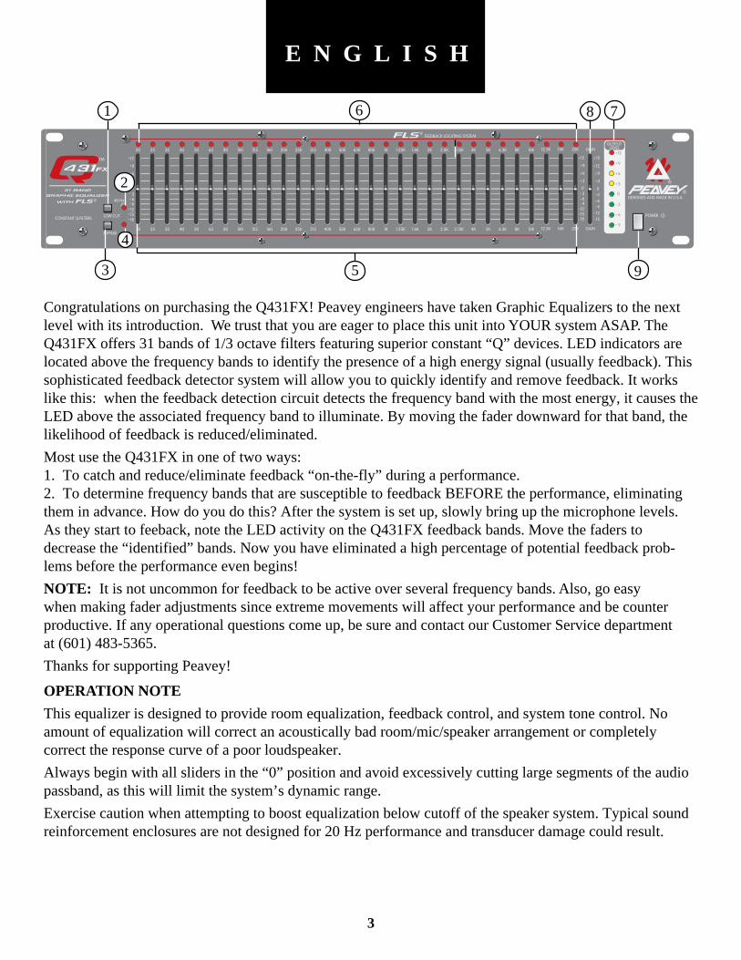
Congratulations on purchasing the Q431FX! Peavey engineers have taken Graphic Equalizers to the nextlevel with its introduction. We trust that you are eager to place this unit into YOUR system ASAP. TheQ431FX offers 31 bands of 1/3 octave filters featuring superior constant “Q” devices. LED indicators arelocated above the frequency bands to identify the presence of a high energy signal (usually feedback). Thissophisticated feedback detector system will allow you to quickly identify and remove feedback. It workslike this: when the feedback detection circuit detects the frequency band with the most energy, it causes theLED above the associated frequency band to illuminate. By moving the fader downward for that band, thelikelihood of feedback is reduced/eliminated.
Most use the Q431FX in one of two ways:1. To catch and reduce/eliminate feedback “on-the-fly” during a performance.2. To determine frequency bands that are susceptible to feedback BEFORE the performance, eliminatingthem in advance. How do you do this? After the system is set up, slowly bring up the microphone levels.As they start to feeback, note the LED activity on the Q431FX feedback bands. Move the faders todecrease the “identified” bands. Now you have eliminated a high percentage of potential feedback prob-lems before the performance even begins!
NOTE: It is not uncommon for feedback to be active over several frequency bands. Also, go easywhen making fader adjustments since extreme movements will affect your performance and be counterproductive. If any operational questions come up, be sure and contact our Customer Service departmentat (601) 483-5365.
Thanks for supporting Peavey!
OPERATION NOTE
This equalizer is designed to provide room equalization, feedback control, and system tone control. Noamount of equalization will correct an acoustically bad room/mic/speaker arrangement or completelycorrect the response curve of a poor loudspeaker.
Always begin with all sliders in the “0” position and avoid excessively cutting large segments of the audiopassband, as this will limit the system’s dynamic range.
Exercise caution when attempting to boost equalization below cutoff of the speaker system. Typical soundreinforcement enclosures are not designed for 20 Hz performance and transducer damage could result.
1
2
6 8 7
3
4
95
4
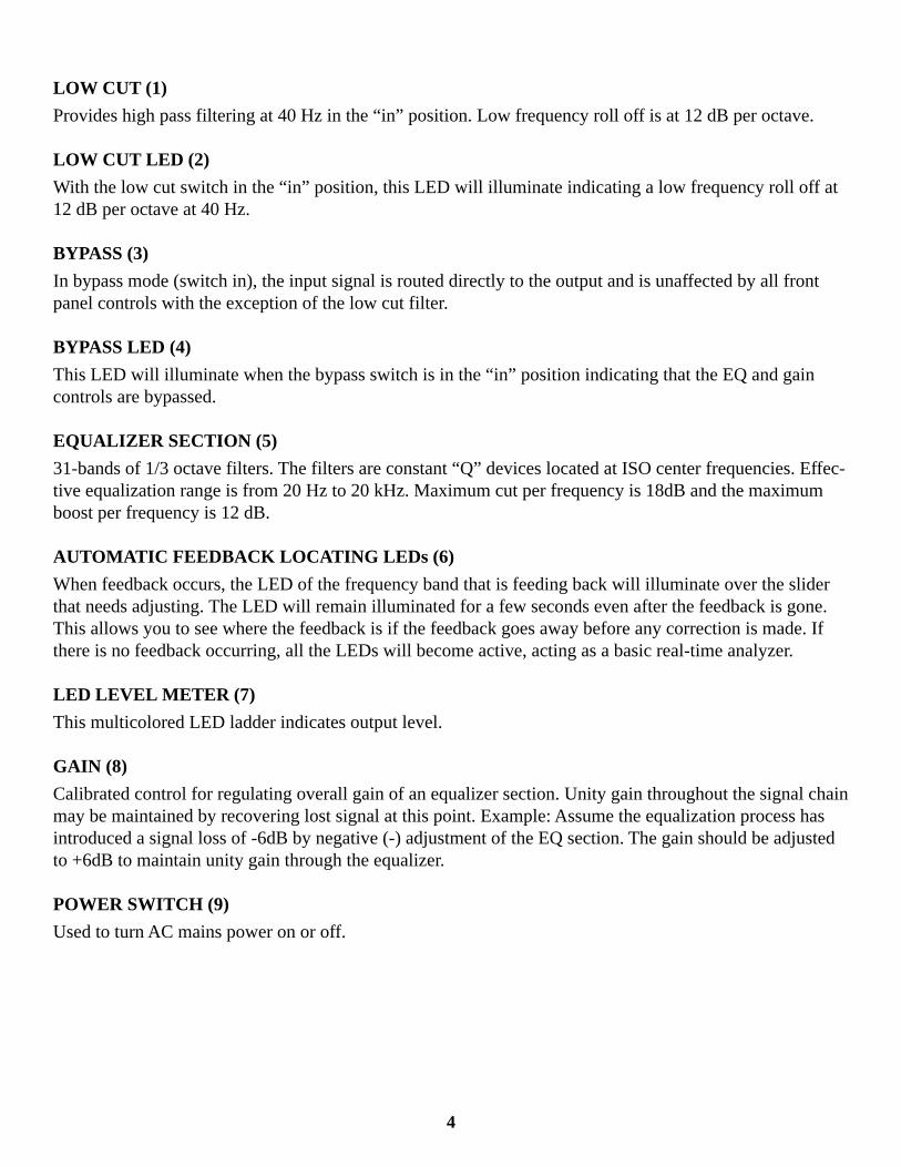
LOW CUT (1)
Provides high pass filtering at 40 Hz in the “in” position. Low frequency roll off is at 12 dB per octave.
LOW CUT LED (2)
With the low cut switch in the “in” position, this LED will illuminate indicating a low frequency roll off at12 dB per octave at 40 Hz.
BYPASS (3)
In bypass mode (switch in), the input signal is routed directly to the output and is unaffected by all frontpanel controls with the exception of the low cut filter.
BYPASS LED (4)
This LED will illuminate when the bypass switch is in the “in” position indicating that the EQ and gaincontrols are bypassed.
EQUALIZER SECTION (5)
31-bands of 1/3 octave filters. The filters are constant “Q” devices located at ISO center frequencies. Effec-tive equalization range is from 20 Hz to 20 kHz. Maximum cut per frequency is 18dB and the maximumboost per frequency is 12 dB.
AUTOMATIC FEEDBACK LOCATING LEDs (6)
When feedback occurs, the LED of the frequency band that is feeding back will illuminate over the sliderthat needs adjusting. The LED will remain illuminated for a few seconds even after the feedback is gone.This allows you to see where the feedback is if the feedback goes away before any correction is made. Ifthere is no feedback occurring, all the LEDs will become active, acting as a basic real-time analyzer.
LED LEVEL METER (7)
This multicolored LED ladder indicates output level.
GAIN (8)
Calibrated control for regulating overall gain of an equalizer section. Unity gain throughout the signal chainmay be maintained by recovering lost signal at this point. Example: Assume the equalization process hasintroduced a signal loss of -6dB by negative (-) adjustment of the EQ section. The gain should be adjustedto +6dB to maintain unity gain through the equalizer.
POWER SWITCH (9)
Used to turn AC mains power on or off.
5
10 11 12 1413
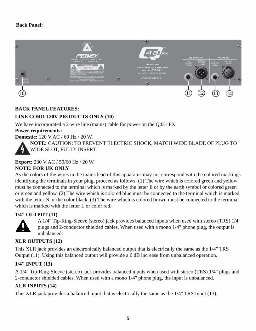
Back Panel:
BACK PANEL FEATURES:
LINE CORD-120V PRODUCTS ONLY (10)
We have incorporated a 2-wire line (mains) cable for power on the Q431 FX.Power requirements:Domestic: 120 V AC / 60 Hz / 20 W.
NOTE: CAUTION: TO PREVENT ELECTRIC SHOCK, MATCH WIDE BLADE OF PLUG TOWIDE SLOT, FULLY INSERT.
Export: 230 V AC / 50/60 Hz / 20 W.NOTE: FOR UK ONLYAs the colors of the wires in the mains lead of this apparatus may not correspond with the colored markingsidentifying the terminals in your plug, proceed as follows: (1) The wire which is colored green and yellowmust be connected to the terminal which is marked by the letter E or by the earth symbol or colored greenor green and yellow. (2) The wire which is colored blue must be connected to the terminal which is markedwith the letter N or the color black. (3) The wire which is colored brown must be connected to the terminalwhich is marked with the letter L or color red.
1/4" OUTPUT (11)A 1/4" Tip-Ring-Sleeve (stereo) jack provides balanced inputs when used with stereo (TRS) 1/4"plugs and 2-conductor shielded cables. When used with a mono 1/4" phone plug, the output isunbalanced.
XLR OUTPUTS (12)
This XLR jack provides an electronically balanced output that is electrically the same as the 1/4" TRSOutput (11). Using this balanced output will provide a 6 dB increase from unbalanced operation.
1/4" INPUT (13)
A 1/4" Tip-Ring-Sleeve (stereo) jack provides balanced inputs when used with stereo (TRS) 1/4" plugs and2-conductor shielded cables. When used with a mono 1/4" phone plug, the input is unbalanced.
XLR INPUTS (14)
This XLR jack provides a balanced input that is electrically the same as the 1/4" TRS Input (13).
6
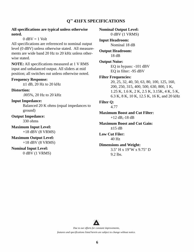
All specifications are typical unless otherwisenoted.
0 dBV = 1 VoltAll specifications are referenced to nominal outputlevel (0 dBV) unless otherwise stated. All measure-ments are wide band 20 Hz to 20 kHz unless other-wise stated.
NOTE: All specifications measured at 1 V RMSinput and unbalanced output. All sliders at midposition; all switches out unless otherwise noted.
Frequency Response:±1 dB, 20 Hz to 20 kHz
Distortion:.005%, 20 Hz to 20 kHz
Input Impedance:Balanced 20 K ohms (equal impedances toground)
Output Impedance:330 ohms
Maximum Input Level:+18 dBV (8 VRMS)
Maximum Output Level:+18 dBV (8 VRMS)
Nominal Input Level:0 dBV (1 VRMS)
Nominal Output Level:0 dBV (1 VRMS)
Input Headroom:Nominal 18 dB
Output Headroom:18 dB
Output Noise:EQ in bypass: -101 dBVEQ in filter: -95 dBV
Filter Frequencies:20, 25, 32, 40, 50, 63, 80, 100, 125, 160,200, 250, 315, 400, 500, 630, 800, 1 K,1.25 K, 1.6 K, 2 K, 2.5 K, 3.15K, 4 K, 5 K,6.3 K, 8 K, 10 K, 12.5 K, 16 K, and 20 kHz
Filter Q:4.77
Maximum Boost and Cut Filter:+12 dB,-18 dB
Maximum Boost and Cut Gain:±15 dB
Low Cut Filer:40 Hz
Dimensions and Weight:3.5" H x 19"W x 9.75" D9.2 lbs.
Q™ 431FX SPECIFICATIONS
Due to our efforts for constant improvements,
features and specifications listed herein are subject to change without notice.
TM®
7
1/3
OC
TAV
E F
ILT
ER
S
Fe
ed
ba
ck
Lo
ca
tor
Fe
ed
ba
ck
Lo
ca
tor
Fe
ed
ba
ck
Lo
ca
tor
Fe
ed
ba
ck
Lo
ca
tor
Fe
ed
ba
ck
Lo
ca
tor
Fe
ed
ba
ck
Lo
ca
tor
Fe
ed
ba
ck
Lo
ca
tor
Fe
ed
ba
ck
Lo
ca
tor
Fe
ed
ba
ck
Lo
ca
tor
Fe
ed
ba
ck
Lo
ca
tor
Fe
ed
ba
ck
Lo
ca
tor
Fe
ed
ba
ck
Lo
ca
tor
Fe
ed
ba
ck
Lo
ca
tor
Fe
ed
ba
ck
Lo
ca
tor
Fe
ed
ba
ck
Lo
ca
tor
Fe
ed
ba
ck
Lo
ca
tor
Fe
ed
ba
ck
Lo
ca
tor
Fe
ed
ba
ck
Lo
ca
tor
Fe
ed
ba
ck
Lo
ca
tor
Fe
ed
ba
ck
Lo
ca
tor
Fe
ed
ba
ck
Lo
ca
tor
Fe
ed
ba
ck
Lo
ca
tor
Fe
ed
ba
ck
Lo
ca
tor
Fe
ed
ba
ck
Lo
ca
tor
Fe
ed
ba
ck
Lo
ca
tor
Fe
ed
ba
ck
Lo
ca
tor
Fe
ed
ba
ck
Lo
ca
tor
Fe
ed
ba
ck
Lo
ca
tor
Fe
ed
ba
ck
Lo
ca
tor
Fe
ed
ba
ck
Lo
ca
tor
GA
IN
(+/-
15
dB
)
20 Hz
32 Hz
50 Hz
80 Hz
125
Hz
200
Hz
315
Hz
500
Hz
800
Hz
1.25
kH
z
2 k
Hz
3.15
kH
z
5 k
Hz
8k
kH
z12
.5 k
Hz
16
kH
z 1
0 k
Hz
6.3
kH
z 4 k
Hz
2.5
kH
z 1
.6 k
Hz
1 kHz
630
Hz
400
Hz
250
Hz
160
Hz
100
Hz
63 Hz
40 Hz
25 Hz
Fe
ed
ba
ck
Lo
ca
tor
20 k
Hz
NO
TE
: EA
CH
FIL
TE
R H
AS
+12
dB
/ -1
8 dB
GA
IN
40 k
Hz
BA
LAN
CE
DIN
PU
T
XLR
INP
UT
LOW
CU
T
BA
LAN
CE
DIN
PU
T A
MP
EQ
BY
PA
SS
OU
TP
UT
AM
P
LED
OU
TP
UT
ME
TE
RX
LRO
UT
PU
T
BA
LAN
CE
D/
UN
BA
LAN
CE
DO
UT
PU
T
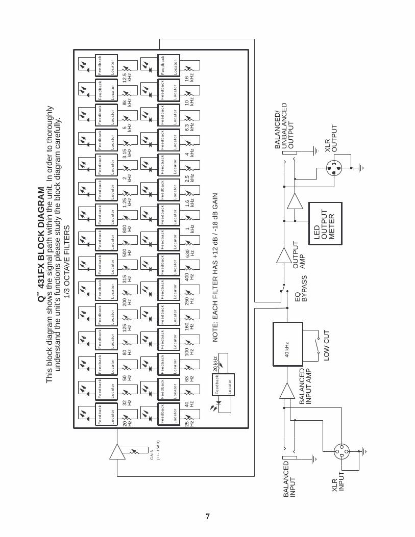
Q
431F
X B
LOC
K D
IAG
RA
MT
his
bloc
k di
agra
m s
how
s th
e si
gnal
pat
h w
ithin
the
unit.
In o
rder
to th
orou
ghly
unde
rsta
nd th
e un
it's
func
tions
ple
ase
stud
y th
e bl
ock
diag
ram
car
eful
ly.
™
8
E S P A Ñ O L
Consulte los diagramas del paneldelantero en la sección de inglés de este manual.
¡Felicidades por tu compra del Q431FX! Los ingenieros de Peavey han llevado los ecualizadores gráficosal siguiente nivel y esperan que estés ansioso por poner YA esta unidad en TU sistema. El Q431FX ofrece31 bandas de filtros de 1/3 de octava que cuentan con dispositivos de constante “Q” superiores. Tieneindicadores LED1 localizados sobre las bandas de frecuencia para identificar la presencia de una señal dealta energía (normalmente retroalimentación). Este sofisticado sistema detector de retroalimentación tepermitirá identificar y eliminar rápidamente la retroalimentación. Funciona así: Cuando el circuito detectorde retroalimentación detecta la banda de frecuencia con la señal de energía más alta, hace que se ilumine elindicador LED de arriba de la banda asociada de frecuencia. Al mover hacia abajo el atenuador de esabanda de frecuencia, se reduce/elimina la probabilidad de retroalimentación.
La mayoría usa el Q431FX de una de dos maneras:1. Para localizar y eliminar o reducir la retroalimentación “al vuelo” durante una actuación.2. Para determinar la bandas de frecuencia que son más susceptibles de retroalimentación ANTES de laactuación y eliminarlas por adelantado. ¿Cómo hacer esto? Después de instalar el sistema, se elevalentamente el nivel de los micrófonos. Al comenzar a retroalimentarse, nota la actividad de los indicadoresLED en las bandas del Q431FX que se retroalimentan. Mueve los atenuadores para disminuir las bandas“identificadas.” ¡Ya has eliminado un alto porcentaje de retroalimentación incluso antes de comenzar laactuación!
NOTA: No es raro que haya retroalimentación activa sobre varias bandas de frecuencia. Asimismo, tencuidado al hacer los ajustes de los atenuadores, ya que los movimientos extremos afectarán tu actuación yserán contraproducentes. Si surge alguna pregunta sobre su operación, asegúrate de comunicarte connuestro depto. de servicio al cliente al 601 483-5365.
Muchas gracias por apoyar a Peavey!
NOTA: Este ecualizador fue diseñado para proveer ecualización de ambiente, control de realimentación ycontrol de tono del sistema. Ninguna cantidad de ecualización corregirá un arreglo de cuarto/micrófono/altavoz que esté acusticamente mal, ni tampoco corregirá completamente la curva de respuesta de unaltavoz deficiente. Comience siempre con todos los controles deslizables en la posición “O” y evite cortarexcesivamente largos segmentos de la banda de audio, cosa que limitaría la gama dinámica del sistema.
Prestar atención al intentar aumentar la igualación por debajo del punto de corte del sistema de altavoces.Los refuerzos típicos de las cajas de altavoces no están diseñados para una potencia de 20 Hz y podríandañarse los transductores.
9
LOW CUT (Corte inferior) (1)Cuando se encuentra oprimido proporciona un filtro de paso en los 40 Hz. La atenuación progresiva de lasfrecuencias bajas es de 12 dB por octava.
LOW CUT LED (LED de corte inferior) (2)Al estar oprimido el conmutador de corte inferior, este diodo emisor de luz se encenderá indicando que estáocurriendo una atenuación progresiva de las bajas frecuencias de 12 dB por octava a los 40 Hz.
BYPASS (Derivación de paso) (3)En el modo de derivación de paso (conmutador oprimido), la señal de entrada se dirige directamente a lasalida y no se ve afectada por los controles del panel anterior, excepto por el filtro de corte inferior.
BYPASS LED (LED de la Derivación de paso) (4)Este diodo emisor de luz se encenderá cuando el conmutador de derivación de paso esté oprimido,indicando que los controles de igualación y de ganancia se han pasado por alto.
EQUALIZER SECTION (Sección de igualación) (5)31 bandas de filtros de 1/3 de octava. Los filtros son dispositivos “Q” constantes ubicados en lasfrecuencias centrales ISO. El rango de igualación efectivo es de 20 Hz a 20 kHz. El recorte o el refuerzomáximo por frecuencia es de 12 dB.
AUTOMATIC FEEDBACK LOCATING LEDs (Indicadores LED localizadores deretroalimentación automáticos (6)Cuando ocurre la retroalimentación automática, el indicador LED de la banda de frecuencia que se estáretroalimentando se encenderá sobre el interruptor deslizante que necesita ajuste. El indicador LEDpermanecerá encendido unos cuantos segundos incluso después de que desaparezca la retroalimentación.Esto te permite ver dónde está la retroalimentación si ésta desaparece antes de hacer cualquier corrección.Si no ocurre ninguna retroalimentación, se activarán todos los indicadores LED, actuando como unanalizador de tiempo real básico.
LED LEVEL METER (Medidor de nivel con LEDs) (7)Este medidor progresivo de diodos emisores de luz de diferentes colores indica el nivel de salida.
GAIN (Ganancia) (8)
Control calibrado usado para regular la ganancia general de la sección de igualadora. En este punto sepuede mantener la ganancia de la unidad a través de la cadena de la señal, recuperando la señal perdida.
Por ejemplo: suponer que el proceso de igualación ha introducido una pérdida de señal de -6 dB al ajustarnegativamente (-) la sección de igualación. Debería entonces ajustarse este control a +6 para mantener laganancia de la unidad a través del igualadora.
POWER SWITCH (Interruptor de corriente) (9)Se utiliza para encender o apagar la fuente principal de corriente alterna.
10
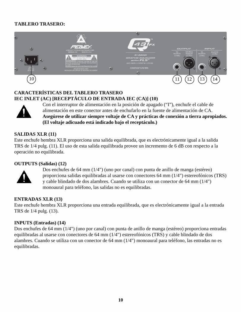
TABLERO TRASERO:
CARACTERÍSTICAS DEL TABLERO TRASEROIEC INLET (AC) [RECEPTÁCULO DE ENTRADA IEC (CA)] (10)
Con el interruptor de alimentación en la posición de apagado (“I”), enchufe el cable dealimentación en este conector antes de enchufarlo en la fuente de alimentación de CA.Asegúrese de utilizar siempre voltaje de CA y prácticas de conexión a tierra apropiados.(El voltaje adicuado está indicado bajo el receptáculo.)
SALIDAS XLR (11)Este enchufe hembra XLR proporciona una salida equilibrada, que es electrónicamente igual a la salidaTRS de 1/4 pulg. (11). El uso de esta salida equilibrada provee un incremento de 6 dB con respecto a laoperación no equilibrada.
OUTPUTS (Salidas) (12)Dos enchufes de 64 mm (1/4") (uno por canal) con punta de anillo de manga (estéreo)proporciona salidas equilibradas al usarse con conectores 64 mm (1/4") estereofónicos (TRS)y cable blindado de dos alambres. Cuando se utiliza con un conector de 64 mm (1/4")monoaural para teléfono, las salidas no es equilibradas.
ENTRADAS XLR (13)Este enchufe hembra XLR proporciona una entrada equilibrada, que es electrónicamente igual a la entradaTRS de 1/4 pulg. (13).
INPUTS (Entradas) (14)Dos enchufes de 64 mm (1/4") (uno por canal) con punta de anillo de manga (estéreo) proporciona entradasequilibradas al usarse con conectores de 64 mm (1/4") estereofónicos (TRS) y cable blindado de dosalambres. Cuando se utiliza con un conector de 64 mm (1/4") monoaural para teléfono, las entradas no esequilibradas.
10 11 141312

11
F R A N C A I SF R A N C A I SF R A N C A I S
Veuillez vous référer au “front panel line art”situé dans la section en langue anglaise de ce manuel.
Toutes nos félicitations d’avoir acheté le Q431FX ! En lançant ce produit, les ingénieurs de Peavey ont faiténormément progresser les égaliseurs graphiques. Ils sont prêts à parier que vous brûlez d’impatienced’intégrer cet appareil dans VOTRE système LE PLUS VITE POSSIBLE. Le Q431FX offre 31 bandesd’un tiers d’octave, dont les filtres à Q constant sont équipés de composants de haute qualité. Desindicateurs à LED, destinés à la détection d’un signal à haute énergie (il s’agit le plus souvent d’unerétroaction), sont situés au-dessus de chaque bande de fréquences. Ce système sophistiqué de détection derétroaction (feedback) vous permet d’identifier et de supprimer rapidement les boucles de rétroaction. Leprincipe de fonctionnement de ce système est le suivant: Lorsque le circuit de détection de rétroactionidentifie la bande de fréquences avec le plus d’énergie, il provoque l’illumination de la LEDcorrespondante. Déplacer l’atténuateur de cette bande vers le bas vous permet de diminuer ou d’annuler laprobabilité d’apparition d’une rétroaction.
Le Q431FX s’utilise principalement de deux manières:1. Pour intercepter et réduire ou éliminer “à la volée” une rétroaction pendant une séance en direct.2. Pour déterminer les bandes de fréquences susceptibles de provoquer une rétroaction AVANT une séanceen direct, afin de les éliminer d’avance. Comment faire ? Après la configuration du système, augmenterprogressivement le niveau des microphones. Dès qu’une rétroaction se produit, noter l’activité des LEDau-dessus des bandes de fréquences du Q431FX. Abaisser ensuite les potentiomètres panoramiques pouratténuer les bandes identifiées”. Vous aurez alors éliminé un pourcentage important des problèmespotentiels de rétroaction, avant même le début de la séance.
REMARQUE: Il n’est pas rare qu’une rétroaction concerne plusieurs bandes de fréquence. Eviter d’avoirla main lourde lors des réglages des potentiomètres, car les mouvements extrêmes peuvent dégrader lesperformances et être contre-productifs. En cas de questions concernant le fonctionnement, n’hésitez pas àcontacter notre service d’assistance à la clientèle au 601-483-5365.
Merci d’avoir choisi Peavey !
NOTE D'UTILISATIONCet égalisateur est conçu pour corriger l’acoustique d’une pièce, contrôler les “feed-backs” et corriger lasonorité du système. Aucune égalisation ne peut arriver à corriger un arrangement pièce/microphone/haut-parleur mal agencé au point de vue acoustique. Commencez toujours avec les curseurs en position “O”vitezde couper excessivement de larges segments de la bande audio, ce qui limiterait le registre dynamique dusystème.
Faire preuve de prudence pour augmenter le niveau d’égalisation au dessous de la mise hors circuit dusystème d’enceintes. Les enceintes de renforcement acoustique n’étant normalement pas conçues pour uneperformance à 20 Hz, le transducteur risque d’être endommagé.

12
LOW CUT (Coupure des basses frequences) (1)Permet d’obtenir un filtrage des hautes fréquences à 40 Hz en position marche («in»). La coupure desbasses fréquences se produit à 12 dB par octave.
LOW CUT LED (Signal DEL de coupure des basses frequences) (2)Lorsque l’interrupteur de coupure des basses fréquences est en position marche («in»), ce voyant DELs’allume pour indiquer la coupure des basses fréquences à 12 dB par octave à 40 Hz.
BYPASS (Dérivation) (3)En mode de dérivation (interrupteur en position marche), le signal d’entrée est directement acheminé versla sortie sans être affecté par les commandes du panneau avant à l’exception du filtre de coupure des bassesfréquences.
BYPASS LED (Signal DEL de dérivation) (4)Ce voyant DEL s’allume quand l’interrupteur de dérivation est en position marche («in»), indiquant que lescommandes de l’égaliseur et du gain sont déviées.
EQUALIZER SECTION (Partie égaliseur) (5)31 bandes de filtres d’un tiers d’octave. Les filtres sont des dispositifs «Q» constants situés à desfréquences centrales ISO. L’amplitude d’égalisation effective s’étend de 20 Hz à 20 kHz. La coupure ouaugmentation maximale par fréquence est 12 dB.
AUTOMATIC FEEDBACK LOCATING LEDs (Diodes de electroluminescentes de localisationautomatique de retroaction) (6)Lorsqu’une rétroaction automatique se produit, la DEL située au-dessus du curseur de la bande defréquence qui nécessite un réglage, s’illumine. Cette DEL reste allumée quelques secondes, même après ladisparition de la rétroaction. Cela permet de localiser la rétroaction si elle disparaît avant que le réglage soiteffectué. S’il n’existe pas de rétroaction, toutes les DEL sont actives, faisant office d’analyseur de spectretemps-réel élémentaire.
LED LEVEL METER (Compteur de niveau LED) (7)Cette échelle de signaux DEL multicolores indique le niveau de sortie.
GAIN (8)Contrôle calibré pour le réglage du gain général de la section EQ. Le gain unitaire de la chaîne detraitement du signal peut être rétabli grâce à ce contrôle.Exemple: Si le réglage d’égalisation induit une perte de -6 dB le contrôle de gain pourra être réglé sur +6pour maintenir un gain unitaire au travers de l’équaliseur.
POWER SWITCH (Interrupteur d'alimentation) (9)Sert à mettre l’alimentation CA principale en circuit (“On”) ou hors circuit (“Off”).
13
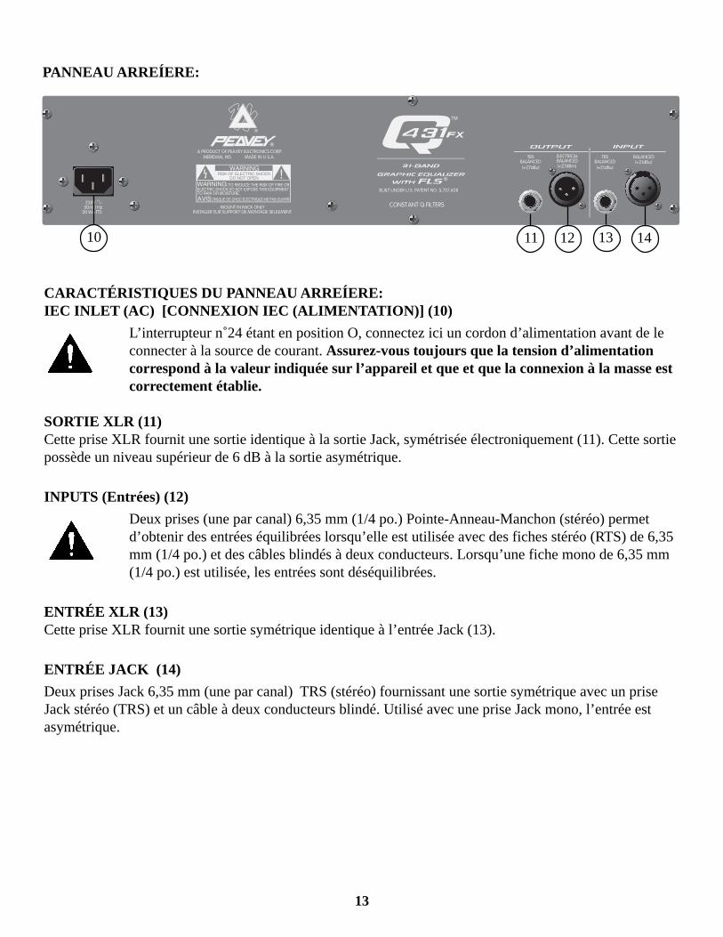
PANNEAU ARREÍERE:
10 11 141312
CARACTÉRISTIQUES DU PANNEAU ARREÍERE:IEC INLET (AC) [CONNEXION IEC (ALIMENTATION)] (10)
L’interrupteur n˚24 étant en position O, connectez ici un cordon d’alimentation avant de leconnecter à la source de courant. Assurez-vous toujours que la tension d’alimentationcorrespond à la valeur indiquée sur l’appareil et que et que la connexion à la masse estcorrectement établie.
SORTIE XLR (11)Cette prise XLR fournit une sortie identique à la sortie Jack, symétrisée électroniquement (11). Cette sortiepossède un niveau supérieur de 6 dB à la sortie asymétrique.
INPUTS (Entrées) (12)
Deux prises (une par canal) 6,35 mm (1/4 po.) Pointe-Anneau-Manchon (stéréo) permetd’obtenir des entrées équilibrées lorsqu’elle est utilisée avec des fiches stéréo (RTS) de 6,35mm (1/4 po.) et des câbles blindés à deux conducteurs. Lorsqu’une fiche mono de 6,35 mm(1/4 po.) est utilisée, les entrées sont déséquilibrées.
ENTRÉE XLR (13)Cette prise XLR fournit une sortie symétrique identique à l’entrée Jack (13).
ENTRÉE JACK (14)
Deux prises Jack 6,35 mm (une par canal) TRS (stéréo) fournissant une sortie symétrique avec un priseJack stéréo (TRS) et un câble à deux conducteurs blindé. Utilisé avec une prise Jack mono, l’entrée estasymétrique.

14
D E U T S C H
Siehe Diagramm der Frontplatte im englischen Teil des Handbuchs.
Herzlichen Glückwunsch zum Erwerb eines Q431FX! Unsere Ingenieure haben mit dem Q431FX eineneue Generation der Graphic Equalizer entwickelt. Dieser Graphic Equalizer verfügt über 31Frequenzbereiche mit 1/3-Oktav-Filtern und überragenden “Constant-Q”. Über den Frequenzbereichen sindLEDs angeordnet, die das Vorhandensein von hochpegeligen Signalen (für gewöhnlich Rückkopplungen)anzeigen. Dieses moderne Rückkopplungs-Detektionssystem hilft dabei, Rückkopplungen schnellfestzustellen und zu beseitigen. Es funktioniert wie folgt: Der Rückkopplungs-Detektionskreis erkennt denFrequenzbereich mit dem höchsten Energieniveau und aktiviert die dazugehörige LED. DurchHerunterschieben des Reglers für diesen Bereich kann die Wahrscheinlichkeit von Rückkopplungenreduziert oder ganz ausgeschaltet werden.
Der Q431FX bietet die folgenden Einsatzmöglichkeiten:1. Sofortiges Erkennen und Reduzieren bzw. Beseitigen von Rückkopplungen während eines Auftritts.2. Feststellen der Frequenzbereiche, in denen Rückkopplung auftreten könnte, und entsprechendeVerringerung der Pegel noch VOR dem Auftritt. Dies geschieht wie folgt: Nach dem Aufstellen der Anlagefahren Sie die Mikrofone langsam hoch. Sobald Rückkopplung auftritt, beachten Sie die LED-Aktivität amQ431FX und schieben Sie die Regler der “identifizierten” Frequenzbereiche nach unten. Auf diese Weisekönnen Sie einen Großteil der potentiellen Rückkopplungsprobleme beseitigen, noch bevor der Auftrittüberhaupt beginnt!
HINWEIS: Es ist nicht ungewöhnlich, daß Rückkopplungen über mehrere Frequenzbereiche auftreten.Nehmen Sie nur geringe Veränderungen der Regler vor, da große Reglerbewegungen die Vorführungbeeinträchtigen und das Gegenteil bewirken können. Wenden Sie sich bei Fragen zu diesem Gerät an IhrenFachhändler oder an eine Peavey-Kundendienststelle (Telefonnr. in den USA: 601-483-5365).Wir danken Ihnen für den Kauf eines Peavey-Gerätes.
MERKE: Deiser Equalizer bietet Raum EQ, Feedback Kontrolle und Klangregelung des Systems. Er kannjedoch nicht akustisch ungünstige Räume, Mikrophone oder Lautsprecher korrigieren oder die Wiedergabeeines schwachen Lautsprechers völlig korrigieren. Immer mit allen Schiebereglern in der “0” Positionbeginnen und große Sprünge im Frequenzbild vermeiden, da diese die Dynamik des Systems einschränken.Eine Verstärkung der Entzerrung unterhalb der Frequenzgrenze des Lautsprechersystems sollte nur mitäußerster Vorsicht durchgeführt werden. Typische Schallverstärkungsgehäuse sind für einen 20 Hz-Betriebnicht geeignet. Der Schwingungsumwandler könnte beschädigt werden.
15
LOW CUT (Tieftonverkürzung) (1)Bietet eine Hochpaß-Filterung bei 40 Hz, wenn der Schalter in der “In-Position” steht. Der Niederfrequenz-Pegelabfall liegt bei 12 dB pro Oktave.
LOW CUT LED (LED für die tieftonverkürzung) (2)Diese LED leuchtet auf, wenn der Schalter für die Tieftonverkürzung in der “In-Position” steht und zeigtan, daß der Niederfrequenz-Pegelabfall 12 dB pro Oktave bei 40 Hz beträgt.
BYPASS (Überbrückung) (3)Im Überbrückungsmodus (Schalter ein) wird das Eingangssignal direkt zum Ausgang geleitet, ohne durchdie Regler an der Vorderseite – mit Ausnahme des Filters für die Tieftonverkürzung – beeinflußt zu werden.
BYPASS LED (LED für die Überbrückung) (4)Diese LED leuchtet auf, wenn der Schalter für den Überbrückungsmodus in der „In-Position“ steht undzeigt an, daß der Equalizer und die Verstärkungsregelung überbrückt werden.
EQUALIZER SECTION (Equalizer-bereich) (5)31-Band 1/3-Oktaven-Filtersätze. Der Q-Faktor der Filter ist konstant und liegt im Bereich ISO-Mittelfrequenzen. Der effektive Entzerrungsbereich liegt zwischen 20 Hz und 20 kHz. Der maximale Cutoder Boost pro Frequenz liegt bei 12 dB.
AUTOMATIC FEEDBACK LOCATING LEDs (LEDs für automatische feststellung vonrückkopplungen) (6)Bei automatischer Rückkopplung leuchtet die LED über dem Schieberegler des Frequenzbereichs, in demdie Rückkopplung auftritt. Die LED leuchtet auch noch einige Sekunden, nachdem die Rückkopplungbeendet ist, weiter. Dadurch kann der Frequenzbereich mit Rückkopplung festgestellt werden, auch wenndie Rückkopplung aufhört, bevor eine Korrektur vorgenommen werden konnte. Wenn keine Rückkopplungvorliegt, sind alle LEDs aktiv und dienen als Echtzeit-Analysator.
LED LEVEL METER (Die LED-pegelanzeige) (7)Die vielfarbige LED-Anzeige zeigt den Ausgabepegel an.
GAIN (Leistungsverstärkung) (8)
Geeichte Kontrolle zur Regulierung des Gesamt-Gainbereichs der Equalizer Sektion. Verluste in derSignalkette (Mixer, Endstufe etc.) können durch diese Funktion ausgeglichen werden.
Beispiel: Angennomen der Klangregelungsprozess erforderte einen Signalverlust von -6 dB. Der Gain-Regler sollte dann auf +6 dB eigestellt werden um eine Übertrangung eines “sauberen” Signals zugewährleisten.
POWER SWITCH (9)Hiermit wird das Gerät ein- und ausgeschaltet.
16
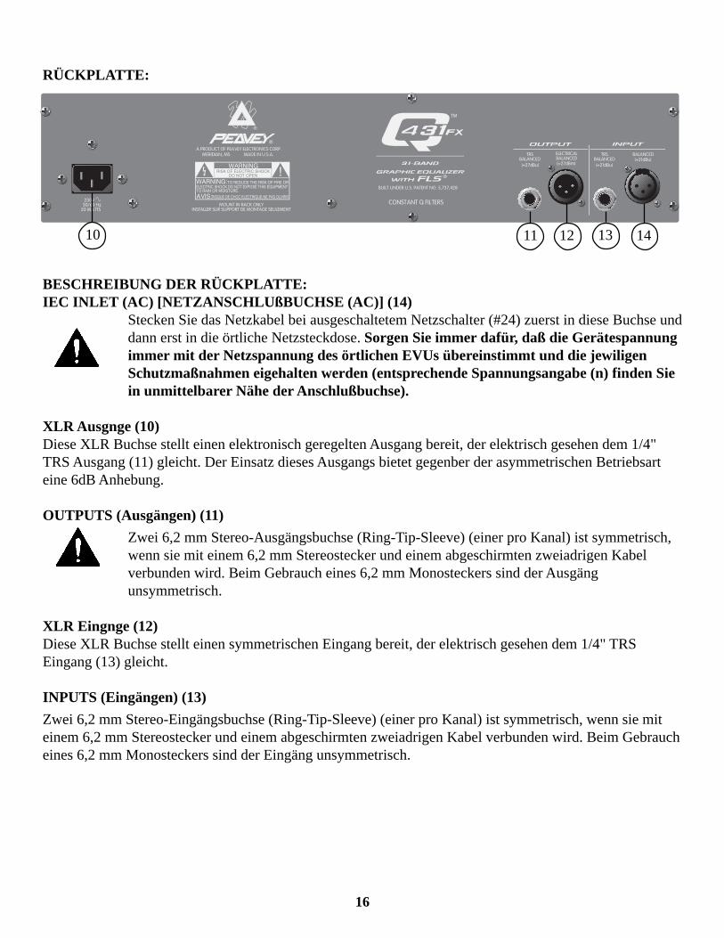
RÜCKPLATTE:
10 11 141312
BESCHREIBUNG DER RÜCKPLATTE:IEC INLET (AC) [NETZANSCHLUßBUCHSE (AC)] (14)
Stecken Sie das Netzkabel bei ausgeschaltetem Netzschalter (#24) zuerst in diese Buchse unddann erst in die örtliche Netzsteckdose. Sorgen Sie immer dafür, daß die Gerätespannungimmer mit der Netzspannung des örtlichen EVUs übereinstimmt und die jewiligenSchutzmaßnahmen eigehalten werden (entsprechende Spannungsangabe (n) finden Siein unmittelbarer Nähe der Anschlußbuchse).
XLR Ausgnge (10)Diese XLR Buchse stellt einen elektronisch geregelten Ausgang bereit, der elektrisch gesehen dem 1/4"TRS Ausgang (11) gleicht. Der Einsatz dieses Ausgangs bietet gegenber der asymmetrischen Betriebsarteine 6dB Anhebung.
OUTPUTS (Ausgängen) (11)
Zwei 6,2 mm Stereo-Ausgängsbuchse (Ring-Tip-Sleeve) (einer pro Kanal) ist symmetrisch,wenn sie mit einem 6,2 mm Stereostecker und einem abgeschirmten zweiadrigen Kabelverbunden wird. Beim Gebrauch eines 6,2 mm Monosteckers sind der Ausgängunsymmetrisch.
XLR Eingnge (12)Diese XLR Buchse stellt einen symmetrischen Eingang bereit, der elektrisch gesehen dem 1/4" TRSEingang (13) gleicht.
INPUTS (Eingängen) (13)
Zwei 6,2 mm Stereo-Eingängsbuchse (Ring-Tip-Sleeve) (einer pro Kanal) ist symmetrisch, wenn sie miteinem 6,2 mm Stereostecker und einem abgeschirmten zweiadrigen Kabel verbunden wird. Beim Gebraucheines 6,2 mm Monosteckers sind der Eingäng unsymmetrisch.
17
For further information on other Peavey products, askyour Authorized Peavey Dealer for the appropriate Peavey
catalog/publication.
Bass Guitars
Guitars
Bass Amplification
Guitar Amplification
Sound Reinforcement Enclosures
Microphones
Keyboards
DJ
Lighting
Mixers, Powered/Non-Powered
Accessories/Cables
Effects Processors
Axcess™ Wear
The Peavey Beat™
Monitor ® Magazine
Key Issues™
Low Down™
TM®

18
FROM QUARK
19
IMPORTANT SAFETY INSTRUCTIONS
WARNING: When using electric products, basic cautions should always be followed, including the following:1. Read these instructions.2. Keep these instructions.3. Heed all warnings.4. Follow all instructions.5. Do not use this apparatus near water. For example, near or in a bathtub, swimming pool, sink, wet
basement, etc.6. Clean only with a damp cloth.7. Do not block any of the ventilation openings. Install in accordance with manufacturer’s instructions. It should not
be placed flat against a wall or placed in a built-in enclosure that will impede the flow of cooling air.8. Do not install near any heat sources such as radiators, heat registers, stoves or other apparatus (including
amplifiers) that produce heat.9. Do not defeat the safety purpose of the polarized or grounding-type plug. A polarized plug has two blades with
one wider than the other. A grounding type plug has two blades and a third grounding plug. The wide blade orthird prong is provided for your safety. When the provided plug does not fit into your inlet, consult an electrician forreplacement of the obsolete outlet. Never break off the grounding write for our free booklet “Shock Hazard andGrounding”. Connect only to a power supply of the type marked on the unit adjacent to the power supply cord.
10. Protect the power cord from being walked on or pinched particularly at plugs, convenience receptacles, and thepoint they exit from the apparatus.
11. Only use attachments/accessories provided by the manufacturer.12. Use only with a cart, stand, tripod,bracket, or table specified by the manufacturer, or sold with the apparatus.
When a cart is used, use caution when moving the cart/apparatus combination to avoid injury from tip-over.13. Unplug this apparatus during lightning storms or when unused for long periods of time.14. Refer all servicing to qualified service personnel. Servicing is required when the apparatus has been damaged in
any way, such as power-supply cord or plug is damaged, liquid has been spilled or objects have fallen into theapparatus, the apparatus has been exposed to rain or moisture, does not operate normally, or has been dropped.
15. If this product is to be mounted in an equipment rack, rear support should be provided.16. Exposure to extremely high noise levels may cause a permanent hearing loss. Individuals vary considerably in
susceptibility to noise induced hearing loss, but nearly everyone will lose some hearing if exposed to sufficientlyintense noise for a sufficient time. The U.S. Government’s Occupational and Health Administration (OSHA) hasspecified the following permissible noise level exposures:
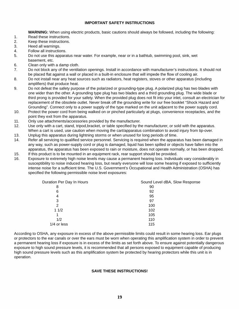
Duration Per Day In Hours Sound Level dBA, Slow Response8 906 924 953 972 100
1 1/2 1021 105
1/2 110 1/4 or less 115
According to OSHA, any exposure in excess of the above permissible limits could result in some hearing loss. Ear plugsor protectors to the ear canals or over the ears must be worn when operating this amplification system in order to preventa permanent hearing loss if exposure is in excess of the limits as set forth above. To ensure against potentially dangerousexposure to high sound pressure levels, it is recommended that all persons exposed to equipment capable of producinghigh sound pressure levels such as this amplification system be protected by hearing protectors while this unit is inoperation.
SAVE THESE INSTRUCTIONS!

20
Peavey Electronics Corporation • 711 A Street • Meridian, MS 39301
(601) 483-5365 • Fax (601) 486-1278 • www.peavey.com
©1998 Printed in U.S.A. 12/9880304532