Embed Size (px)
Citation preview

PN 3672225 March 2011, Rev. 1 © 2011 Fluke Corporation. All rights reserved. Printed in USA. Specifications are subject to change without notice. All product names are trademarks of their respective companies.
QA-ES Automation Bundle ESU Automation Kit
Users Manual

Notices
All Rights Reserved Copyright 2011, Fluke Biomedical. No part of this publication may be reproduced, transmitted, transcribed, stored in a retrieval system, or translated into any language without the written permission of Fluke Biomedical.
Copyright Release Fluke Biomedical agrees to a limited copyright release that allows you to reproduce manuals and other printed materials for use in service training programs and other technical publications. If you would like other reproductions or distributions, submit a written request to Fluke Biomedical.
Unpacking and Inspection Follow standard receiving practices upon receipt of the instrument. Check the shipping carton for damage. If damage is found, stop unpacking the instrument. Notify the carrier and ask for an agent to be present while the instrument is unpacked. There are no special unpacking instructions, but be careful not to damage the instrument when unpacking it. Inspect the instrument for physical damage such as bent or broken parts, dents, or scratches.
Technical Support For application support or answers to technical questions, either email [email protected] or call 1-800- 648-7952 or 1-425-446-6945.
Claims Our routine method of shipment is via common carrier, FOB origin. Upon delivery, if physical damage is found, retain all packing materials in their original condition and contact the carrier immediately to file a claim. If the instrument is delivered in good physical condition but does not operate within specifications, or if there are any other problems not caused by shipping damage, please contact Fluke Biomedical or your local sales representative.
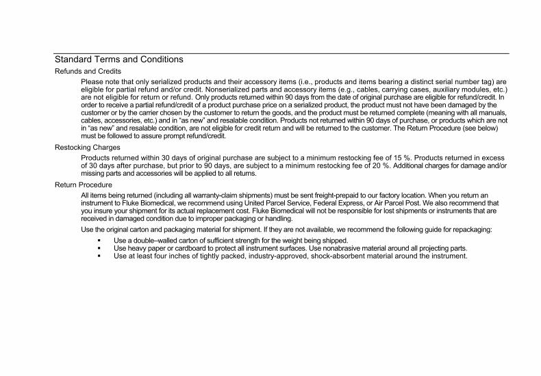
Standard Terms and Conditions Refunds and Credits
Please note that only serialized products and their accessory items (i.e., products and items bearing a distinct serial number tag) are eligible for partial refund and/or credit. Nonserialized parts and accessory items (e.g., cables, carrying cases, auxiliary modules, etc.) are not eligible for return or refund. Only products returned within 90 days from the date of original purchase are eligible for refund/credit. In order to receive a partial refund/credit of a product purchase price on a serialized product, the product must not have been damaged by the customer or by the carrier chosen by the customer to return the goods, and the product must be returned complete (meaning with all manuals, cables, accessories, etc.) and in “as new” and resalable condition. Products not returned within 90 days of purchase, or products which are not in “as new” and resalable condition, are not eligible for credit return and will be returned to the customer. The Return Procedure (see below) must be followed to assure prompt refund/credit.
Restocking Charges
Products returned within 30 days of original purchase are subject to a minimum restocking fee of 15 %. Products returned in excess of 30 days after purchase, but prior to 90 days, are subject to a minimum restocking fee of 20 %. Additional charges for damage and/or missing parts and accessories will be applied to all returns.
Return Procedure
All items being returned (including all warranty-claim shipments) must be sent freight-prepaid to our factory location. When you return an instrument to Fluke Biomedical, we recommend using United Parcel Service, Federal Express, or Air Parcel Post. We also recommend that you insure your shipment for its actual replacement cost. Fluke Biomedical will not be responsible for lost shipments or instruments that are received in damaged condition due to improper packaging or handling.
Use the original carton and packaging material for shipment. If they are not available, we recommend the following guide for repackaging:
Use a double–walled carton of sufficient strength for the weight being shipped. Use heavy paper or cardboard to protect all instrument surfaces. Use nonabrasive material around all projecting parts. Use at least four inches of tightly packed, industry-approved, shock-absorbent material around the instrument.
Returns for partial refund/credit:
Every product returned for refund/credit must be accompanied by a Return Material Authorization (RMA) number, obtained from our Order Entry Group at 1-800-648-7952 or 1-425-446-6945.
Repair and calibration:
To find the nearest service center, go to www.flukebiomedical.com/service or In the U.S.A.: Cleveland Calibration Lab Tel: 1-800-850-4606 Email: [email protected] Everett Calibration Lab Tel: 1-888-99 FLUKE (1-888-993-5853) Email: [email protected] In Europe, Middle East, and Africa: Eindhoven Calibration Lab Tel: +31-402-675300 Email: [email protected] In Asia: Everett Calibration Lab Tel: +425-446-6945 Email: [email protected]
Certification This instrument was thoroughly tested and inspected. It was found to meet Fluke Biomedical’s manufacturing specifications when it was shipped from the factory. Calibration measurements are traceable to the National Institute of Standards and Technology (NIST). Devices for which there are no NIST calibration standards are measured against in-house performance standards using accepted test procedures.
WARNING Unauthorized user modifications or application beyond the published specifications may result in electrical shock hazards or improper operation. Fluke Biomedical will not be responsible for any injuries sustained due to unauthorized equipment modifications.
Restrictions and Liabilities Information in this document is subject to change and does not represent a commitment by Fluke Biomedical. Changes made to the information in this document will be incorporated in new editions of the publication. No responsibility is assumed by Fluke Biomedical for the use or reliability of software or equipment that is not supplied by Fluke Biomedical, or by its affiliated dealers.
Manufacturing Location The QA-ES Automation Bundle is manufactured at Fluke Biomedical, 6920 Seaway Blvd., Everett, WA, U.S.A.
i
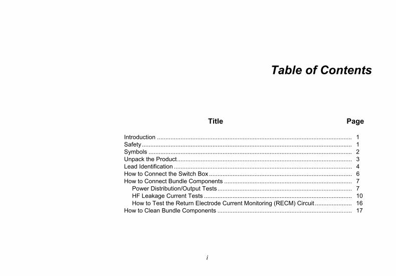
Table of Contents
Title Page
Introduction .................................................................................................................... 1 Safety ............................................................................................................................. 1 Symbols ......................................................................................................................... 2 Unpack the Product........................................................................................................ 3 Lead Identification .......................................................................................................... 4 How to Connect the Switch Box ..................................................................................... 6 How to Connect Bundle Components ............................................................................ 7
Power Distribution/Output Tests................................................................................ 7 HF Leakage Current Tests ........................................................................................ 10 How to Test the Return Electrode Current Monitoring (RECM) Circuit ...................... 16
How to Clean Bundle Components ................................................................................ 17

QA-ES Automation Bundle Users Manual
ii
1
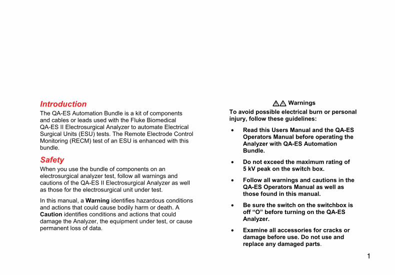
Introduction The QA-ES Automation Bundle is a kit of components and cables or leads used with the Fluke Biomedical QA-ES II Electrosurgical Analyzer to automate Electrical Surgical Units (ESU) tests. The Remote Electrode Control Monitoring (RECM) test of an ESU is enhanced with this bundle.
Safety When you use the bundle of components on an electrosurgical analyzer test, follow all warnings and cautions of the QA-ES II Electrosurgical Analyzer as well as those for the electrosurgical unit under test.
In this manual, a Warning identifies hazardous conditions and actions that could cause bodily harm or death. A Caution identifies conditions and actions that could damage the Analyzer, the equipment under test, or cause permanent loss of data.
Warnings
To avoid possible electrical burn or personal injury, follow these guidelines:
• Read this Users Manual and the QA-ES Operators Manual before operating the Analyzer with QA-ES Automation Bundle.
• Do not exceed the maximum rating of 5 kV peak on the switch box.
• Follow all warnings and cautions in the QA-ES Operators Manual as well as those found in this manual.
• Be sure the switch on the switchbox is off “O” before turning on the QA-ES Analyzer.
• Examine all accessories for cracks or damage before use. Do not use and replace any damaged parts.
QA-ES Automation Bundle Users Manual
2
• Follow all Bundle setup instructions and stand clear when you activate the QA-ES Analyzer with the switch box.
• Do not use probes or accessories supplied for use with the QA-ES for handheld use.
• Use Bundle accessories only in the manner specified in this manual.
• Use only Fluke Biomedical supplied accessories. Do not substitute off-the-shelf cables for those supplied in the Bundle.
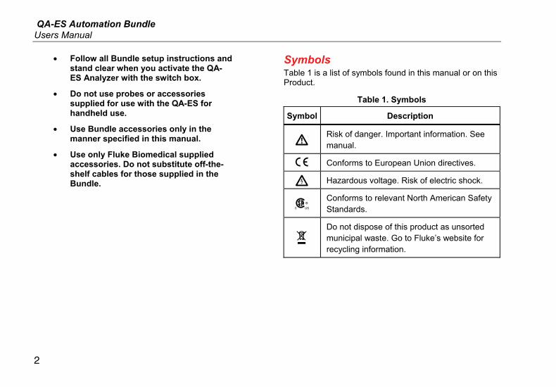
Symbols Table 1 is a list of symbols found in this manual or on this Product.
Table 1. Symbols
Symbol Description
Risk of danger. Important information. See manual.
Conforms to European Union directives.
Hazardous voltage. Risk of electric shock.
Conforms to relevant North American Safety Standards.
Do not dispose of this product as unsorted municipal waste. Go to Fluke’s website for recycling information.
ESU Automation Kit Unpack the Product
3
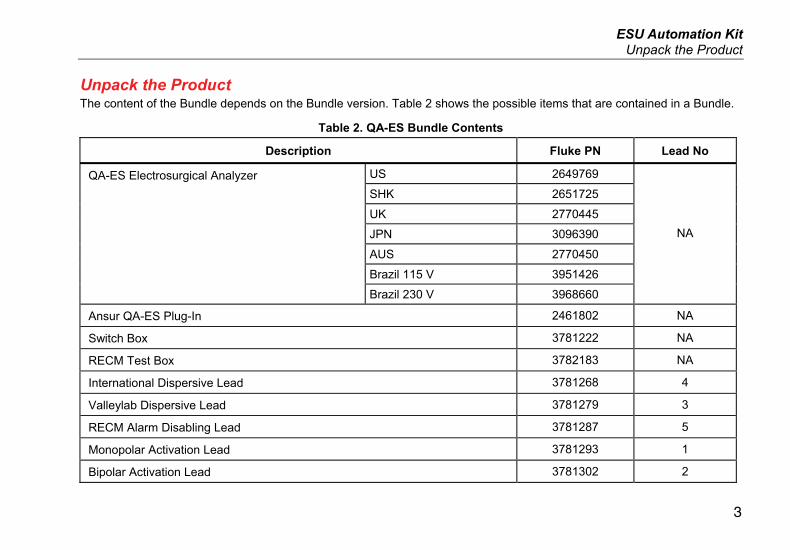
Unpack the Product The content of the Bundle depends on the Bundle version. Table 2 shows the possible items that are contained in a Bundle.
Table 2. QA-ES Bundle Contents
Description Fluke PN Lead No
US 2649769
SHK 2651725
UK 2770445
JPN 3096390
AUS 2770450
Brazil 115 V 3951426
QA-ES Electrosurgical Analyzer
Brazil 230 V 3968660
NA
Ansur QA-ES Plug-In 2461802 NA
Switch Box 3781222 NA
RECM Test Box 3782183 NA
International Dispersive Lead 3781268 4
Valleylab Dispersive Lead 3781279 3
RECM Alarm Disabling Lead 3781287 5
Monopolar Activation Lead 3781293 1
Bipolar Activation Lead 3781302 2
QA-ES Automation Bundle Users Manual
4
Table 2. QA-ES Bundle Contents (cont.)
Description Fluke PN Lead No
QA-ES Automation Kit Users Manual 3672225 NA
20 Inch Black Safety Lead 3782216
20 Inch Red Safety Lead 3782233 6
40 Inch Black Safety Lead 3837016
40 Inch Red Safety Lead 3837025 7
Test Probe Set, 0.080 Brass Tip 1909216 8
RS232 Cable with Ferrites 3788956 NA
Carrying Case 3766325 NA
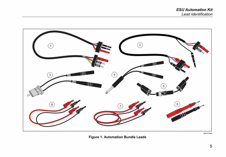
Lead Identification To help identify which lead is used in each of the test configurations shown in this manual, use Figure 1 and Table 2.
In the configuration figures to follow, some lead connections are identified with a call out. Use the lead number in a configuration graphic to find the correct lead in Figure 1. To help with identification, the same lead number is used in Table 2.
ESU Automation Kit Lead Identification
5
1 2
3
76
5
4
8
giw12.eps
Figure 1. Automation Bundle Leads
QA-ES Automation Bundle Users Manual
6
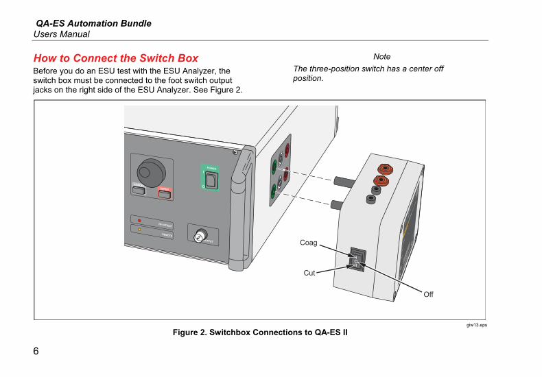
How to Connect the Switch Box Before you do an ESU test with the ESU Analyzer, the switch box must be connected to the foot switch output jacks on the right side of the ESU Analyzer. See Figure 2.
Note
The three-position switch has a center off position.
POWER
ENTER
CANCEL
RF-DETECT
REMOTESCOPE OUTPUT
EVERETT, WA 98203
Coag
Cut
Off
giw13.eps
Figure 2. Switchbox Connections to QA-ES II
ESU Automation Kit How to Connect Bundle Components
7
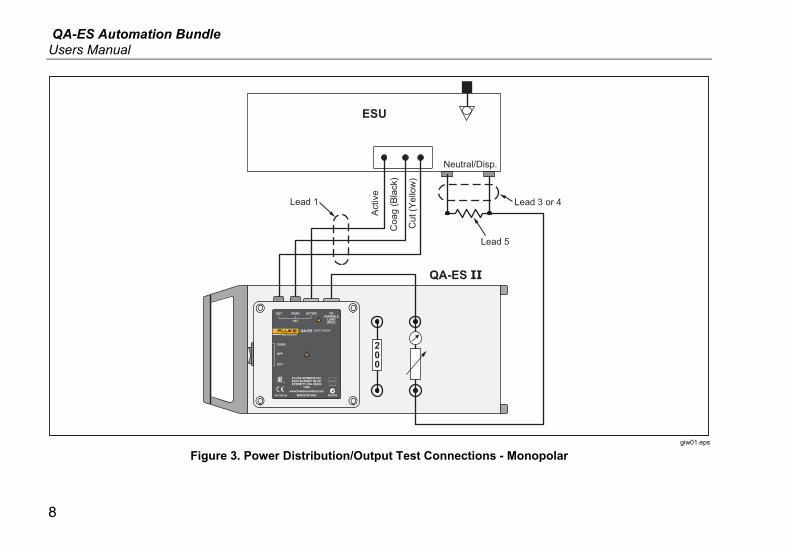
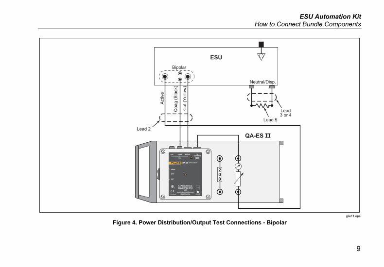
How to Connect Bundle Components Figures 3 through 11 shows the connections made between the ESU Analyzer and the Unit Under Test (UUT) for different ESU tests. These connections, although equivalent to those in the QA-ES II Operators Manual, show how the components of this Bundle must be connected.
Power Distribution/Output Tests Power Distribution/Output tests measure the power output properties of the ESU and supply output current (A), power (W), peak-to-peak voltage (V), and crest factor values. Figure 3 shows how to connect the Bundle for Monopolar mode and Figure 4 shows the connections for Bipolar mode.
QA-ES Automation Bundle Users Manual
8
200
ESU
QA-ES II
Activ
e
Neutral/Disp.
Coa
g (B
lack
)
Cut
(Yel
low
)
Lead 3 or 4Lead 1
Lead 5
giw01.eps
Figure 3. Power Distribution/Output Test Connections - Monopolar
ESU Automation Kit How to Connect Bundle Components
9
200
ESU
QA-ES II
Act
ive
Neutral/Disp.
Coa
g (B
lack
)
Cut
(Yel
low
)
Lead3 or 4
Lead 5
Lead 2
Bipolar
giw11.eps
Figure 4. Power Distribution/Output Test Connections - Bipolar
QA-ES Automation Bundle Users Manual
10
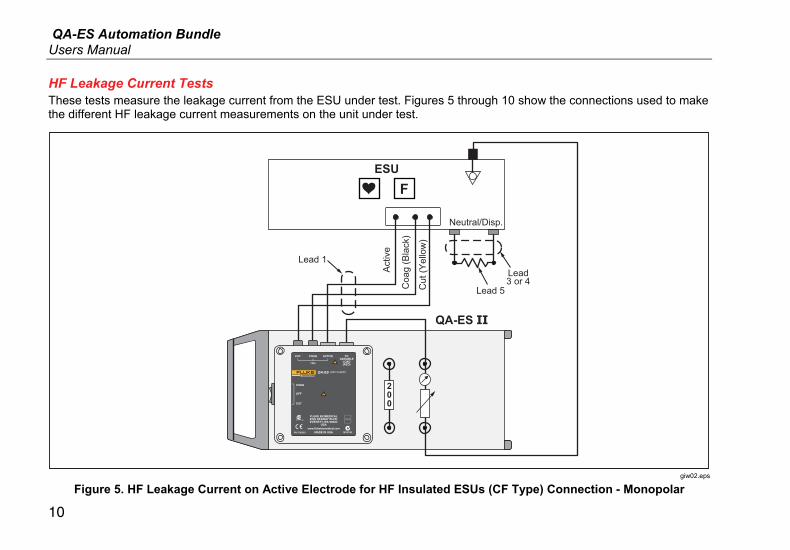
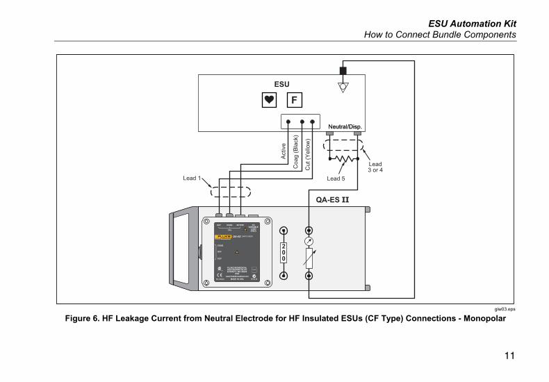
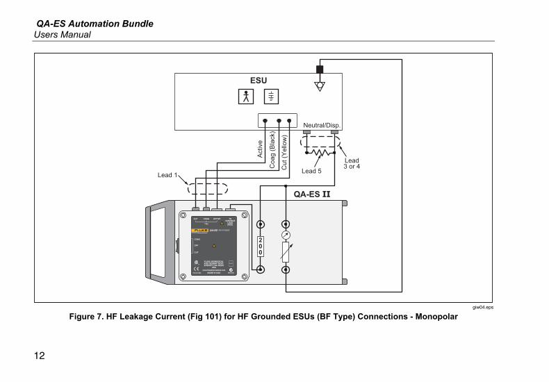
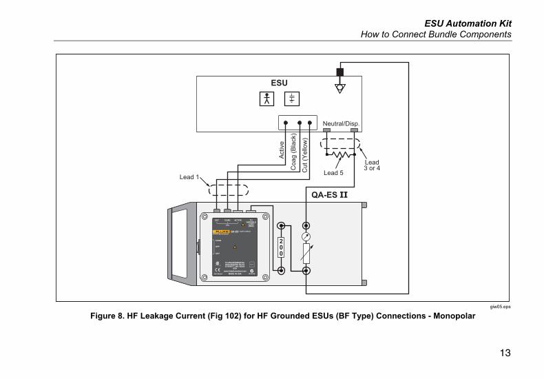
HF Leakage Current Tests These tests measure the leakage current from the ESU under test. Figures 5 through 10 show the connections used to make the different HF leakage current measurements on the unit under test.
ESU
QA-ES II
Activ
e
Coa
g (B
lack
)
Cut
(Yel
low
)
F
200
Neutral/Disp.
Lead3 or 4
Lead 1
Lead 5
giw02.eps
Figure 5. HF Leakage Current on Active Electrode for HF Insulated ESUs (CF Type) Connection - Monopolar
ESU Automation Kit How to Connect Bundle Components
11
ESU
Activ
e
Coa
g (B
lack
)
Cut
(Yel
low
)
F
Neutral/Disp.
200
QA-ES II
Neutral/Disp.
Lead3 or 4
Lead 1 Lead 5
giw03.eps
Figure 6. HF Leakage Current from Neutral Electrode for HF Insulated ESUs (CF Type) Connections - Monopolar
QA-ES Automation Bundle Users Manual
12
Activ
e
Coa
g (B
lack
)
Cut
(Yel
low
)
Neutral/Disp.
200
ESU
QA-ES II
Lead3 or 4
Lead 1 Lead 5
giw04.eps
Figure 7. HF Leakage Current (Fig 101) for HF Grounded ESUs (BF Type) Connections - Monopolar
ESU Automation Kit How to Connect Bundle Components
13
1 Kv
Act
ive
Cut
(Yel
low
)
ESU
QA-ES II
Coa
g (B
lack
)
200
Neutral/Disp.
Lead3 or 4
Lead 1 Lead 5
giw05.eps
Figure 8. HF Leakage Current (Fig 102) for HF Grounded ESUs (BF Type) Connections - Monopolar
QA-ES Automation Bundle Users Manual
14
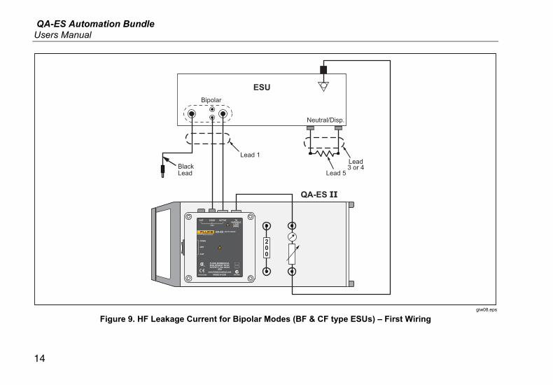
ESU
QA-ES II
200
Neutral/Disp.
Bipolar
BlackLead
Lead3 or 4
Lead 5
Lead 1
giw08.eps
Figure 9. HF Leakage Current for Bipolar Modes (BF & CF type ESUs) – First Wiring
ESU Automation Kit How to Connect Bundle Components
15
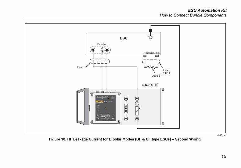
ESU
QA-ES II
200
Neutral/Disp.
Bipolar
Lead3 or 4
Lead 1
Lead 5
giw09.eps
Figure 10. HF Leakage Current for Bipolar Modes (BF & CF type ESUs) – Second Wiring.
QA-ES Automation Bundle Users Manual
16
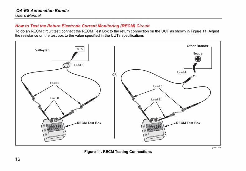
How to Test the Return Electrode Current Monitoring (RECM) Circuit To do an RECM circuit test, connect the RECM Test Box to the return connection on the UUT as shown in Figure 11. Adjust the resistance on the test box to the value specified in the UUTs specifications
Lead 6
RECM Test Box
Valleylab
Lead 3
Lead 8
Lead 6
Lead 8
RECM Test Box
Other Brands
Neutral
ORLead 4
giw10.eps
Figure 11. RECM Testing Connections
ESU Automation Kit How to Clean Bundle Components
17
How to Clean Bundle Components
Warning
To avoid electric shock, do not clean the bundle components while connected to the Analyzer or UUT.
Caution
Do not pour fluid onto the bundle component surfaces; fluid seepage into the electrical circuitry may cause the component to fail.
Do not use spray cleaners on the components; such action may force cleaning fluid into the components and damage electronic components.
Clean the bundle components utilizing a damp cloth and mild detergent. Take care to prevent the entrance of fluids.
Wipe down the adapter cables with the same care. Inspect them for damage to and deterioration of the insulation. Check the connections for integrity before each use.

QA-ES Automation Bundle Users Manual
18