Embed Size (px)
Citation preview
QA-ST MKII Electrical Safety Tester
(US Model)
Getting Started Guide
QA-ST MKII – Getting Started Guide
i
Copyright © 2005 by Fluke Electronics Corporation. All rights reserved. Fluke Electronics Corporation Biomedical Systems (METRON Product Group) 5200 Convair Drive Carson City, NV 89706
Customer Support and Sales Phone (US Toll Free): 800.648.7952 Phone (Outside the US): 775.883.3400 FAX: 775.883.9541 E-Mail: [email protected] Internet: www.flukebiomedical.com
Service Phone (US Toll Free): 888.993.5853 Phone (Outside the US): 425.446.5560 E-Mail: [email protected]
Notices
Disclaimer METRON provides this publication as is without warranty of any kind, either express or implied, including but not limited to the implied warranties of merchantability or fitness for any particular purpose. Further, METRON reserves the right to revise this publication and to make changes from time to time to the content hereof, without obligation on the part of METRON or its local representatives to notify any person of such revision or changes. Some jurisdictions do not allow disclaimers of expressed or implied warranties in certain transactions; therefore, this statement may not apply to you.
Limited Warranty METRON warrants that the QA-ST MKII Electrical Safety Tester will substantially conform to published specifications and to the documentation, provided that it is used for the purpose for which it was designed. METRON will, for a period of twelve (12) months from date of purchase, replace or repair any defective simulator, if the fault is due to a manufacturing defect. In no event will METRON or its local representatives be liable for direct, indirect, special, incidental, or consequential damages arising out of the use of or inability to use the QA-ST MKII Electrical Safety Tester, even if advised of the possibility of such damages. METRON and its local representatives are not responsible for any costs, loss of profits, loss of data, or claims by third parties due to use of, or inability to use the QA-ST MKII Electrical Safety Tester. Neither METRON nor its local representatives will accept, nor be bound by any other form of guarantee concerning the QA-ST MKII Electrical Safety Tester other than this guarantee. Some jurisdictions do not allow disclaimers of expressed or implied warranties in certain transactions; therefore, this statement may not apply to you.
Safety Notice The QA-ST MKII Electrical Safety Tester performs tests in accordance with several electrical safety standards. In the process of this testing, voltages of up to 300 Vac may be present in the test leads, outlet, and/or enclosure of the Device Under Test. Use all applicable electrical safety measures.
QA-ST MKII – Getting Started Guide
Table of Contents Notices......................................................................................... i
1 Terms and Abbreviations ........................................................... 1
2 Setup for Manual Testing ........................................................... 1
3 Setup for Automated Testing ..................................................... 2
4 Tests............................................................................................. 2 AC/DC Measurement Selection .......................................... 2 OE – Open Earth Test ......................................................... 2 ON – Open Neutral Test...................................................... 2 RM – Reverse Mains Test ................................................... 3 Mains Voltage Test ............................................................. 3 Protective Earth Test ........................................................... 3 Earth Leakage Current Test................................................. 3 Enclosure Leakage Current Test ......................................... 3 Patient Leakage Current Lead-to-Ground Test ................... 4 Patient Leakage Current Lead-to-Lead Test........................ 4 Mains on Applied Part Test................................................. 4
Appendix A ................................................................ Specifications
Appendix B..................................................... Ordering Information
QA-ST MKII – Getting Started Guide
1
1 Terms and Abbreviations
Chassis = Enclosure DUT = Device Under Test Earth = Ground Enclosure = Chassis Ground = Earth NC = Normal Condition OE = Open Earth ON = Open Neutral RM = Reverse Mains
This symbol indicates that mains voltage or higher will be present in the test leads. In addition, the enclosure may be raised to mains voltage levels or higher.
2 Setup for Manual Testing
1. Plug the unit into a wall outlet with power.
2. Confirm that the only lights illuminated are the two lights in the inlet power indicator (boxed in blue). If either of these lights is not illuminated, or if any other combination of lights is illuminated, examine the wall outlet for problems in grounding or polarity. NOTE: DO NOT USE extension cords or power strips when testing with the QA-ST MKII.
3. Connect the test cable to the Enclosure port on the right side of the unit.
4. Connect the test cable clamp to the metal enclosure of your DUT.
5. Connect the patient leads to the Patient leads ports in numerical order.
6. Perform any of the QA-ST MKII electrical safety tests.
QA-ST MKII – Getting Started Guide
2
3 Setup for Automated Testing
1. Perform all steps under “Setup for Manual Testing” on the previous page.
2. Connect one end of the NULL-modem cable to the RS-232 port on the left side of the QA-ST MKII.
3. Connect the other end of the NULL-modem cable to an applicable COM port on your computer.
4. Consult the ansur test executive User Manual and the ansur QA-ST Plug-In User Manual for instructions on building and executing the automated test templates.
5. Perform any of the QA-ST MKII electrical safety tests.
4 Tests
For each test listed below, the following information is provided: test name, unit of measure, and options. (“Options” include assorted, user-selectable power conditions, as well as the AC/DC measurement selection.) AC/DC Measurement Selection To select AC or DC measurements when the selection is available, press the AC/DC button. The display will reflect the change in measurement type.
OE – Open Earth Test This test will break the connection of the Earth power line to the DUT. To select Open Earth measurements when the selection is available, press the open gnd button. The display will reflect the change in measurement type.
ON – Open Neutral Test This test will break the connection of the Neutral/L2 power line to the DUT. To select Open Neutral measurements when the selection is available, press the open neutral button. The display will reflect the change in measurement type.
QA-ST MKII – Getting Started Guide
3
(Tests, continued)
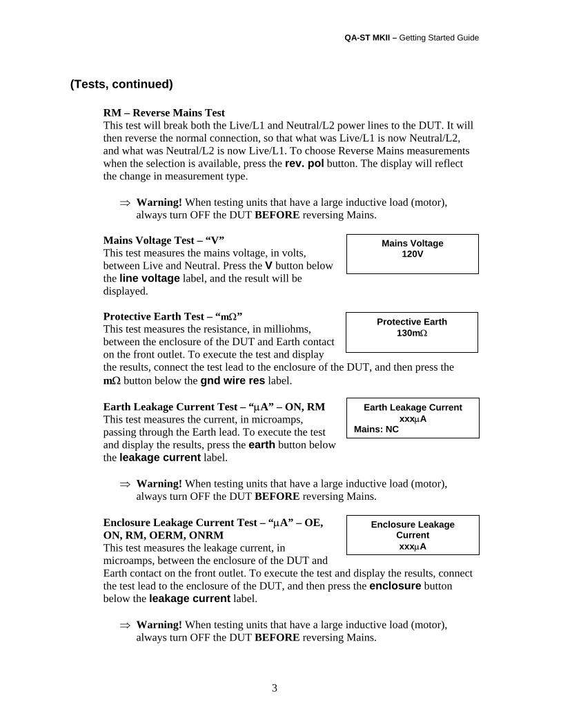
RM – Reverse Mains Test This test will break both the Live/L1 and Neutral/L2 power lines to the DUT. It will then reverse the normal connection, so that what was Live/L1 is now Neutral/L2, and what was Neutral/L2 is now Live/L1. To choose Reverse Mains measurements when the selection is available, press the rev. pol button. The display will reflect the change in measurement type.
⇒ Warning! When testing units that have a large inductive load (motor), always turn OFF the DUT BEFORE reversing Mains.
Mains Voltage Test – “V” This test measures the mains voltage, in volts, between Live and Neutral. Press the V button below the line voltage label, and the result will be displayed.
Protective Earth Test – “mΩ” This test measures the resistance, in milliohms, between the enclosure of the DUT and Earth contact on the front outlet. To execute the test and display the results, connect the test lead to the enclosure of the DUT, and then press the mΩ button below the gnd wire res label.
Earth Leakage Current Test – “µA” – ON, RM This test measures the current, in microamps, passing through the Earth lead. To execute the test and display the results, press the earth button below the leakage current label.
⇒ Warning! When testing units that have a large inductive load (motor), always turn OFF the DUT BEFORE reversing Mains.
Enclosure Leakage Current Test – “µA” – OE, ON, RM, OERM, ONRM This test measures the leakage current, in microamps, between the enclosure of the DUT and Earth contact on the front outlet. To execute the test and display the results, connect the test lead to the enclosure of the DUT, and then press the enclosure button below the leakage current label.
⇒ Warning! When testing units that have a large inductive load (motor), always turn OFF the DUT BEFORE reversing Mains.
Protective Earth 130mΩ
Enclosure Leakage Current xxxµA
Earth Leakage Current xxxµA
Mains: NC
Mains Voltage 120V
QA-ST MKII – Getting Started Guide
4
(Tests, continued)
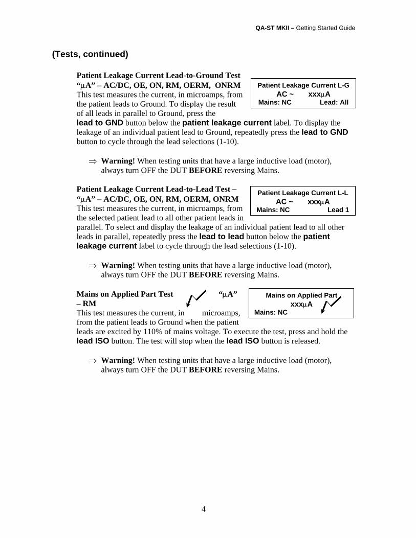
Patient Leakage Current Lead-to-Ground Test “µA” – AC/DC, OE, ON, RM, OERM, ONRM This test measures the current, in microamps, from the patient leads to Ground. To display the result of all leads in parallel to Ground, press the lead to GND button below the patient leakage current label. To display the leakage of an individual patient lead to Ground, repeatedly press the lead to GND button to cycle through the lead selections (1-10).
⇒ Warning! When testing units that have a large inductive load (motor), always turn OFF the DUT BEFORE reversing Mains.
Patient Leakage Current Lead-to-Lead Test – “µA” – AC/DC, OE, ON, RM, OERM, ONRM This test measures the current, in microamps, from the selected patient lead to all other patient leads in parallel. To select and display the leakage of an individual patient lead to all other leads in parallel, repeatedly press the lead to lead button below the patient leakage current label to cycle through the lead selections (1-10).
⇒ Warning! When testing units that have a large inductive load (motor), always turn OFF the DUT BEFORE reversing Mains.
Mains on Applied Part Test “µA” – RM This test measures the current, in microamps, from the patient leads to Ground when the patient leads are excited by 110% of mains voltage. To execute the test, press and hold the lead ISO button. The test will stop when the lead ISO button is released.
⇒ Warning! When testing units that have a large inductive load (motor), always turn OFF the DUT BEFORE reversing Mains.
Patient Leakage Current L-GAC ~ xxxµA
Mains: NC Lead: All
Patient Leakage Current L-LAC ~ xxxµA
Mains: NC Lead 1
Mains on Applied Part xxxµA
Mains: NC
QA-ST MKII – Getting Started Guide
5
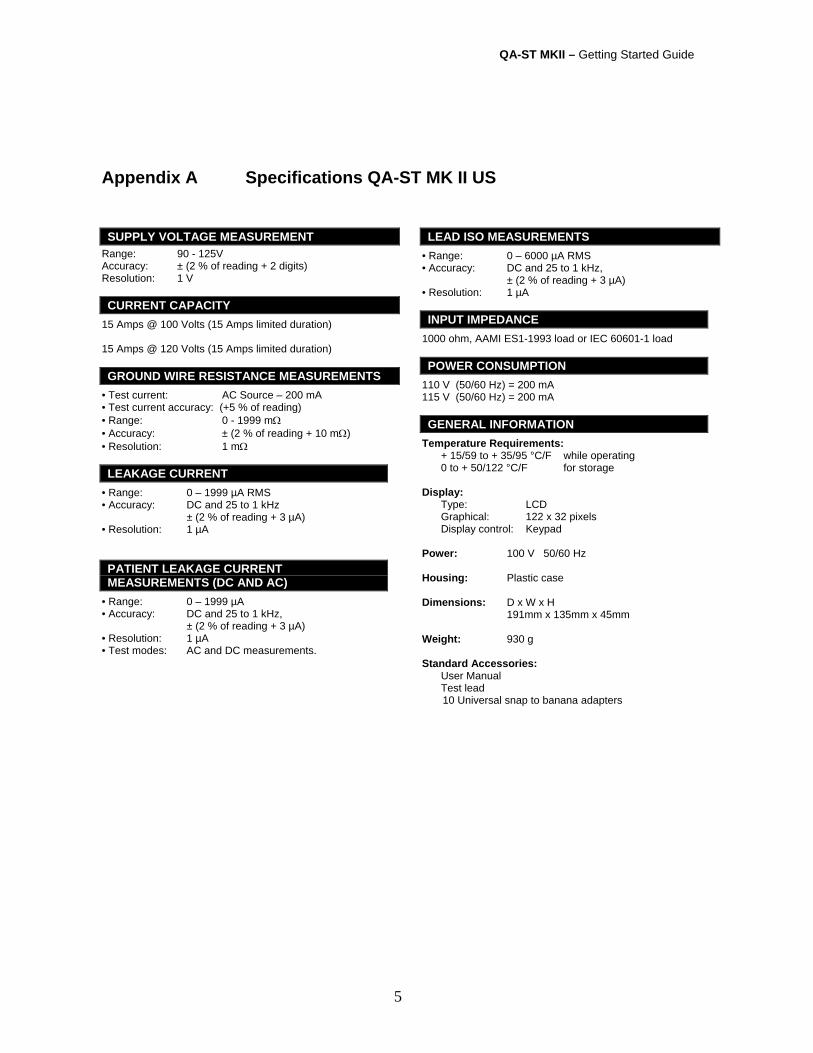
Appendix A Specifications QA-ST MK II US SUPPLY VOLTAGE MEASUREMENT
Range: 90 - 125V Accuracy: ± (2 % of reading + 2 digits) Resolution: 1 V CURRENT CAPACITY
15 Amps @ 100 Volts (15 Amps limited duration) 15 Amps @ 120 Volts (15 Amps limited duration) GROUND WIRE RESISTANCE MEASUREMENTS
• Test current: AC Source – 200 mA • Test current accuracy: (+5 % of reading) • Range: 0 - 1999 mΩ • Accuracy: ± (2 % of reading + 10 mΩ) • Resolution: 1 mΩ LEAKAGE CURRENT
• Range: 0 – 1999 µA RMS • Accuracy: DC and 25 to 1 kHz ± (2 % of reading + 3 µA) • Resolution: 1 µA PATIENT LEAKAGE CURRENT MEASUREMENTS (DC AND AC)
• Range: 0 – 1999 µA • Accuracy: DC and 25 to 1 kHz, ± (2 % of reading + 3 µA) • Resolution: 1 µA • Test modes: AC and DC measurements.
LEAD ISO MEASUREMENTS • Range: 0 – 6000 µA RMS • Accuracy: DC and 25 to 1 kHz, ± (2 % of reading + 3 µA) • Resolution: 1 µA INPUT IMPEDANCE
1000 ohm, AAMI ES1-1993 load or IEC 60601-1 load POWER CONSUMPTION
110 V (50/60 Hz) = 200 mA 115 V (50/60 Hz) = 200 mA GENERAL INFORMATION
Temperature Requirements: + 15/59 to + 35/95 °C/F while operating 0 to + 50/122 °C/F for storage Display: Type: LCD Graphical: 122 x 32 pixels Display control: Keypad Power: 100 V 50/60 Hz Housing: Plastic case Dimensions: D x W x H 191mm x 135mm x 45mm Weight: 930 g Standard Accessories: User Manual Test lead 10 Universal snap to banana adapters
QA-ST MKII – Getting Started Guide
6
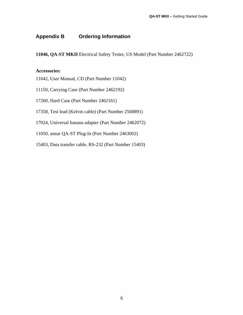
Appendix B Ordering Information 11046, QA-ST MKII Electrical Safety Tester, US Model (Part Number 2462722) Accessories: 11042, User Manual, CD (Part Number 11042) 11150, Carrying Case (Part Number 2462192) 17260, Hard Case (Part Number 2462161) 17358, Test lead (Kelvin cable) (Part Number 2568891) 17024, Universal banana adapter (Part Number 2462072) 11050, ansur QA-ST Plug-In (Part Number 2463002) 15403, Data transfer cable, RS-232 (Part Number 15403)