Embed Size (px)
Citation preview

Fitted Options- Power Supply: 24V Output Option Card: 1-Current 2-Relays Channel1: Cond Channel2: Cond Channel3: Cond
Mains 3-Current 0-Relays pH/Redox pH/Redox pH/Redox
3-Current 4-Relays ECS ECS ECS
5-Current 2-Relays DO DO DO
Modbus 4-Relays Aux mA IP Aux mA IP Aux mA IP
SS SS SS
MXD75 Quick Start Guide
Relay Connection Details
MXD75 Instrument Dimensions
74 mm
300 mm
6 mm x 3 o�
8 mm
74 mm
Power Connection DetailsCAUTION!Always remove the main power from the system before any alterations to the wiring. Ensure that both power lines are isolated. Make sure that the power cannot be switched on by accident whilst the instrument is being connected. For safety reasons an earth connection must be made to the earth terminal of this instrument.
Local wiring and safety regulations should be strictly adhered to when installing this instrument. If the installation methods and cable types recommended in this guide are followed, then the instrument will achieve the levels of EMC protection as speci�ed in the accompanying CD manual.
Consult the serial label on the side of the instrument for supply voltage requirements.
Power Supply“Live” In
Power Supply“Live” Out
(For Daisy Chaining)
Power Supply“Neutral” In
Power Supply “Neutral” Out(For Daisy Chaining)
Protective Earth(Must Be Connected)
Earth
L+
N-
L+
N-
Earth
Earth
Power Connector
85V-265V AC/DC Power Supply Connection Details
Power Supply“+” In
Power Supply“+” Out
(For DaisyChaining)
Power Supply “-” In
Power Supply“-” Out(For Daisy Chaining)
Protective Earth(Must Be Connected)
Earth
L+
N-
L+
N-
Earth
Earth
Power Connector
18V-32V AC/DC Power Supply Connection Details
Relay Connection DetailsAvailable Relays Vary Depending On Instrument Con�guration
5-6
NO3 C3 NC3
NO2 C2 NC2
NO1 C1 NC1
NO6C6
NO5C5
NO4 C4 NC4
Relay 1Normally
OpenContact
Relay 1CommonContact
Relay 1Normally
ClosedContact
Relay 2Normally
OpenContact
Relay 2CommonContact
Relay 2Normally
ClosedContact
NO1 C1 NC1 NO2 C2 NC2 NC3NO3 C3
Relay 3CommonContact
Relay 3Normally
OpenContact
Relay 3Normally
ClosedContact
Relay 4Normally
OpenContact
Relay 4CommonContact
Relay 4Normally
ClosedContact
Relay 5Normally
OpenContact
Relay 5CommonContact
Relay 6Normally
ClosedContact
NO4 C4 NC4 C5 NO5 C6 NO6
Relay 6Normally
OpenContact
Relays 1 - 3 Connector Relays 4 - 6 Connector
LTH recommends using No. 10 x 1¼ inch round head screws or similar for mounting.
Ensure top screw head is 8 mm proud.
Care must be taken when �tting the unit on uneven walls or surfaces. Do not over stress the mounting lugs.
Over tightening the mounting screws could also break the lugs. Drill Hole Dimensions
110 mm
CH3
CH2
CH1
85-265V 15W_~
1 4 7
2 5 8
3 6
G
G
G
DIGITALINPUTS
SENSOR INPUT 3
SENSOR INPUT 2
SENSOR INPUT 1
L+
N-
L+
N-
SD CARD0/4-20 mAOUTPUT
1
2
A+ - A A B B G E C
A + -+-E E R RA B B
A A B B + -+-R R D D
CONDUCTIVITY
PH / REDOX
ECS CONDUCTIVITY
5-6
A+
B+
C+
D+ -
-
-
0/4-20 mAOUTPUTS
32
1
6
54
Power SupplyInput
Relays
Current Outputs/ Modbus RS485
Channel 1 Input
Channel 2Input
Channel 3Input
DigitalInputs SD Card
Slot
Earth Studs
EthernetPort
(FutureExpansion)
Exact Instrument Con�guration DependsUpon Ordered Speci�cation
MON 1 JUN 200909:56
CH1: 517.2 µS/cm TEMP1: 12.3°CCH2: 9.64 pHCH3: 23.3%
TEMP2: 25.0°CTEMP3: 28.0°C
MAIN MENU
DIGITAL INPUTS
CHANNELS
EXIT
4-20mA OUTPUTS
CALIBRATIONSETPOINT / RELAYS
CONFIGURATION
CURSOR
FURTHER MENU PAGES BELOW
INSTRUMENTREADINGS
CURRENTDATE / TIME
UNIT STATUS
FURTHER MENU PAGES ABOVE
MON 1 JUN 200909:56
CH1: 517.2 µS/cm TEMP1: 12.3°CCH2: 9.64 pHCH3: 23.3%
TEMP2: 25.0°CTEMP3: 28.0°C
SETPOINT 1 SETUP
INPUT SOURCE:RANGE:TRIGGER:HIGH VALUE:MODE:
CHANNEL:
SENSOR0 to 9.999 mS/cmHIGH7.500mS/cmON/OFF
EXIT
CHANNEL 1 (COND)
LOWBANDLATCH HIGH
TRIGGERHIGH
LATCH LOW
CURSOR
ADDITIONALOPTIONS BELOW
OPTION POP-UP
MON 1 JUN 200909:56
CH1: 517.2 µS/cm TEMP1: 12.3°CCH2: 9.64 pHCH3: 23.3%
TEMP2: 25.0°CTEMP3: 28.0°C
CHANNEL 1 SETUP
UNITS:CELL CONSTANT:RANGE:TEMP INPUT SENSOR:TEMPERATURE UNITS:
MODE:SIEMENS(S/cm)1.000AUTOPT1000°C
EXIT
ON-LINESECURITY CODE
CODEENTER ACCESS
* * *0
User Interface Overview
Scrolling Menu Layout
Front Layout
Main Menu Layout
Pop-Up Option Layout
Security Access Pop-Up
To protect the instrument setup from unauthorised or accidental tampering, a security access code system is present. This is implemented via the instrument’s menu system which operates in two modes, “locked” as indicated by a padlock symbol and “unlocked” as indicated by a key symbol.
Fourth Issue September 2016For con�guration and calibration information please consult the operational manuals on the accompanying CD.
The default Access Code is: 1000
Front ScreenCurrentOutput
Bargraphs
ChannelsSetup
Setpoint /Relays Setup
4-20mAOutputs Setup
DigitalInputs Setup
ErrorMessages
Live Trends1, 2 & 3*
*Optional Extra
CAL
SETPOINT STATUSLEDS
SETPOINT STATUSLEDS
ALARM STATUSLEDS
09:56MON 1 JUN 2009
CH1: 517.2 µS/cmi) ii)12.3°C
A: 12.28mA
CH2: 9.64 pHi) ii)25.0°C -156mV
CH3: 23.3 %i) ii)28.0°C 2.15Atm
MENU
CAL
CONTEXT SENSITIVE BUTTON FUNCTIONS
UNIT STATUS
CURRENT TIME
CHANNELMESSAGES
CHANNEL SECONDARY READING ii
CURRENT DATE
CHANNEL PRIMARYREADING
CHANNEL ID
CHANNEL SECONDARYREADING i
CHANNEL ALARMSTATUS
TANK 1
TANK 3
CHANNELLABEL
A+
C+
D+E+
F+
--
-
0/4-20 mAOUTPUTS
B+
Current Output Connector
Current Output A+
CurrentOutput B+
B+ C+ D+ E+ F+
CurrentOutput D+
CurrentOutput -
(Common)
CurrentOutput E+
CurrentOutput C+
CurrentOutput F+
CurrentOutput -
(Common)
Current Output Connection Details
A+ - - -
CurrentOutput -
(Common)
Current Output & Modbus Connection Details
-MODBUS RS485
& 0/4-20 mA OUTPUT
Modbus and Current Output Connector
Current Output A+
CurrentOutput -
(Common)
Modbus AConenction
(Inverting)(Rx-/Tx-) Modbus B
Connection(Non-Inverting)
(Rx+/Tx+)
Modbus and Current OutputConnection Details
A+mA
Modbus CConnection(0V Reference)Optional
-mA
A-485
B+485
CG485
A+mA
A-485
B+485
CG485 mA
Available Current Output and Modbus Connections Vary Depending UponInstrument Con�guration
Temperature Connection DetailsSensor Input Connector
Link Link
RTD
2 Wire RTDTemperature Connection
A A B BSensor Input Connector
RTD
3 Wire RTDTemperature Connection
Link
A A B B
Sensor Input Connector
Link
22K ThermistorTemperature Connection
Link
Thermistor
A A B B T
(Only Available On Dissolved Oxygen Input Card)
Sensor Input Connector
RTD
4 Wire RTDTemperature Connection
A A B B
Digital Input Connection Details
G 1 2 3 4 5 6 7 8
Digital Input Connector
1 4 72 5 8
3 6
GG
G
Digital Input Connection Details
PO Box 1142PukekoheAuckland2340New Zealand
Telephone: +64 (0) 9 234 4609email: [email protected]: www.quadbeam.co.nz
SKT5
SKT6
SKT7
HEADER A
HEADER B
HEADER C
HEADER D OR E
COMMS A
COMMS B
CH3
CH2
CH1
85-250V 15W_~
1 4 7
2 5 8
3 6
G
G
G
DIGITALINPUTS
SENSOR INPUT 3
SENSOR INPUT 2
SENSOR INPUT 1
L+
N-
L+
N-
SD CARD
LINKACT
0/4-20 mAOUTPUT
1
2
A+ -
A A B B G E C
A + -+-E E R RA B B
A A B B + -+-R R D D
CONDUCTIVITY
PH / REDOX
ECS CONDUCTIVITY5-6
A+
B+
C+
D+ -
-
-
0/4-20 mAOUTPUTS
32
1
6
54
F1F2 F3 F4
F5
09:56MON 1 JUN 2009
CH1: 517.2 µS/cmi) ii)12.3°C
A: 12.28mA
CH2: 9.64 pHi) ii)25.0°C -156mV
CH3: 23.3 %i) ii)28.0°C 2.15Atm
MENU
CAL
242 mm
331 mm
09:56MON 1 JUN 2009
CH1: 517.2 µS/cmi) ii)12.3°C
A: 12.28mA
CH2: 9.64 pHi) ii)25.0°C -156mV
CH3: 23.3 %i) ii)28.0°C 2.15Atm
MENU
CAL
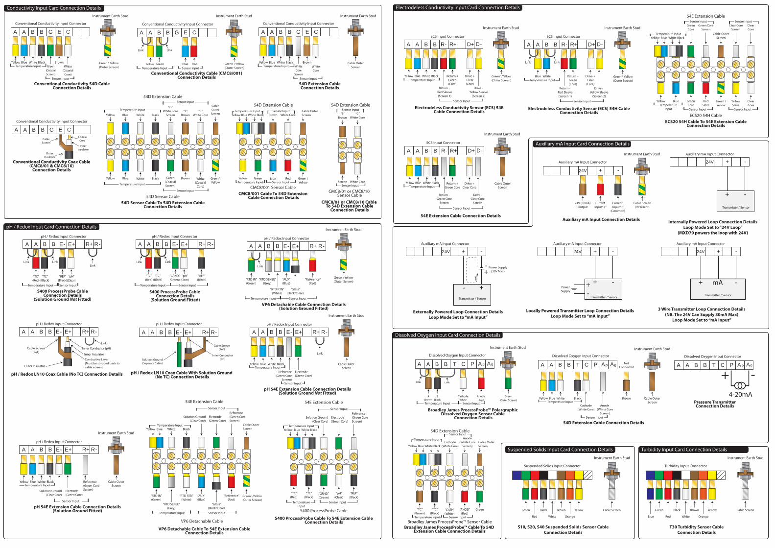
Externally Powered Loop Connection DetailsLoop Mode Set to “mA Input”
Auxiliary mA Input Connector
24V + -
Transmitter / Sensor
- +
+-
Power Supply(36V Max)
mA
Locally Powered Transmitter Loop Connection DetailsLoop Mode Set to “mA Input”
Auxiliary mA Input Connector
24V + -
Transmitter / Sensor
+ -+-
PowerSupply
Internally Powered Loop Connection DetailsLoop Mode Set to “24V Loop”
(MXD70 powers the loop with 24V)
Auxiliary mA Input Connector
24V + -
Transmitter / Sensor
+ -
3 Wire Transmitter Loop Connection Details(NB. The 24V Can Supply 30mA Max)
Loop Mode Set to “mA Input”
Auxiliary mA Input Connector
24V + -
Transmitter / Sensor
-+ mA
Auxiliary mA Input Card Connection Details
Auxiliary mA Input Connection Details
Auxiliary mA Input Connector
Current Input “-”
(Common)
Current Input “+”
24V (30mA)Output
24V + -
Instrument Earth Stud
Cable Screen(If Present)
pH / Redox LN10 Coax Cable With Solution Ground (No TC) Connection Details
Solution Ground(Seperate Cable)
pH / Redox Input Connector
A + -+-E E R RA B B
Inner Conductor(pH)
Cable Screen(Ref )
pH / Redox LN10 Coax Cable (No TC) Connection Details
Link
Inner Conductor (pH)
Inner Insulator
Conductive Layer(Must be stripped back tocable screen)Outer Insulator
Cable Screen(Ref )
pH / Redox Input Connector
A + -+-E E R RA B B
pH / Redox Input Card Connection Details
Link
“TC”(Red)
“TC”(Black)
“pH”(Clear)
“REF”(Black)
S400 ProcessProbe CableConnection Details
(Solution Ground Not Fitted)
LinkLink
pH / Redox Input Connector
A + -+-E E R RA B B
Temperature Input Sensor Input
Link
“TC”(Red)
“TC”(Black)
“pH”(Clear)
“GRND”(Green)
S400 ProcessProbe Cable Connection Details
(Solution Ground Fitted)
Link
“REF”(Black)
pH / Redox Input Connector
A + -+-E E R RA B B
Temperature Input Sensor Input
VP6 Detachable Cable Connection Details(Solution Ground Fitted)
Green \ Yellow(Outer Screen)
Temperature Input Sensor Input
“RTD IN”(Green)
“RTD SENSE”(Grey)
“RTD RTN”(White)
“AUX”(Blue)
“Glass”(Black/Clear)
“Reference”(Red)
pH / Redox Input Connector
A + -+-E E R RA B B
Instrument Earth Stud
Link
Electrode(Green Core)
54E Extension CableSensor Input
Yellow Blue White BlackTemperature Input
Reference(Green CoreScreen)
Solution Ground(Clear Core)
“TC”(Black)
“GRND”(Green)
“pH”(Clear)
“TC”(Red)
“REF”(Black)
TemperatureInput
Sensor Input
S400 ProcessProbe Cable
S400 ProcessProbe Cable To 54E Extension CableConnection Details
54E Extension Cable
VP6 Detachable Cable
VP6 Detachable Cable To 54E Extension CableConnection Details
Electrode(Green Core)
Sensor Input
Yellow Blue White BlackTemperature Input
Reference(Green CoreScreen)
Solution Ground(Clear Core)
Cable OuterScreen
Temperature Input Sensor Input
“RTD IN”(Green)
“RTD SENSE”(Grey)
“AUX”(Blue)
“Reference”(Red)
“RTD RTN”(White)
“Glass”(Black/Clear)
Green \ Yellow(Outer Screen)
Yellow Blue White Black
Reference(Green Core
Screen)
Electrode(Green Core)
pH 54E Extension Cable Connection Details(Solution Ground Not Fitted)
Cable Outer Screen
Link
Temperature Input
Sensor Input
pH / Redox Input Connector
A + -+-E E R RA B B
Instrument Earth Stud
Yellow Blue White Black
Solution Ground(Clear Core)
Electrode(Green Core)
pH 54E Extension Cable Connection Details(Solution Ground Fitted)
Cable OuterScreenTemperature Input
Sensor Input
Reference(Green CoreScreen)
pH / Redox Input Connector
A + -+-E E R RA B B
Instrument Earth Stud
Conductivity Input Card Connection Details
White Core
54D Extension CableSensor Input
Yellow Blue White BlackTemperature Input Cable Outer
ScreenBrown
Green Blue RedYellow Green \YellowTemperature Input Sensor Input
CMC8/001 Sensor CableCMC8/001 Cable To 54D Extension
Cable Connection Details
“C”White Core
54D Extension CableSensor Input
“E”Brown
Screen White CoreSensor Input
CMC8/01 or CMC8/10 Sensor Cable
CMC8/01 or CMC8/10 Cable To 54D Extension Cable
Connection Details
Yellow Blue White BlackWhiteCore
Screen
WhiteCore
Brown
54D Extension CableConnection Details
Cable OuterScreen
Instrument Earth Stud
Conventional Conductivity Input Connector
A A B B G E C
Sensor Input
Temperature Input
“C”White Core
54D Extension CableSensor Input
Yellow Blue White Black
Temperature InputCableOuterScreen
“E”Brown
Blue White BlackYellow Green \YellowTemperature Input
Sensor Input
54D Sensor Cable54D Sensor Cable To 54D Extension Cable
Connection Details
“G”White Core
Screen
Green(CoaxialScreen)
Brown White(Coaxial
Core)
Link
Yellow Green RedBlue
Conventional Conductivity Cable (CMC8/001)Connection Details
Green \ Yellow(Outer Screen)
Instrument Earth Stud
Conventional Conductivity Input Connector
Link
A A B B G E C
Sensor InputTemperature Input
Yellow Blue White BlackGreen
(CoaxialScreen)
White(Coaxial
Core)
Brown
Conventional Conductivity 54D CableConnection Details
Green \ Yellow(Outer Screen)
Instrument Earth Stud
Conventional Conductivity Input Connector
A A B B G E C
Sensor Input
Temperature Input
Conventional Conductivity Coax Cable(CMC8/01 & CMC8/10)
Connection Details
CoaxialCore
InnerInsulator
OuterInsulator
CableScreen
Conventional Conductivity Input Connector
A A B B G E C
Electrodeless Conductivity Input Card Connection Details
GreenCore
54E Extension CableSensor Input
Yellow Blue White BlackTemperature Input
ClearCore
Green CoreScreen
Blue RedSleve
GreenCore
Yellow ClearCoreTemperature
Input
ECS20 54H CableECS20 54H Cable To 54E Extension Cable
Connection Details
YellowSleve
Clear CoreScreen
Cable OuterScreen
Green \Yellow
Sensor Input
Sensor Input Sensor Input
Yellow Blue White Black
Drive -Clear Core
Screen
Drive +Clear Core
54E Extension Cable Connection Details
Cable OuterScreen
Return +Green Core
Return -Green Core
Screen
Sensor Input
Temperature Input
ECS Input Connector
A A B B + -+-R R D D
Instrument Earth Stud
ECS Input Connector
A A B B + -+-R R D D
Instrument Earth Stud
Yellow Blue White Black
Drive - Yellow Sleeve
(Screen 2)
Drive +Clear(Core)
Electrodeless Conductivity Sensor (ECS) 54ECable Connection Details
Green \ Yellow(Outer Screen)
Return +Green(Core)
Return - Red Sleeve(Screen 1)
Temperature Input
Sensor Input
Link Link
ECS Input Connector
A A B B + -+-R R D D
Instrument Earth Stud
Electrodeless Conductivity Sensor (ECS) 54H CableConnection Details
Green \ Yellow(Outer Screen)
Blue White
Drive - Yellow Sleeve
(Screen 2)
Drive +Clear(Core)
Return +Green(Core)
Return - Red Sleeve(Screen 1)
Temperature Input
Sensor Input
Dissolved Oxygen Input Card Connection Details
Dissolved Oxygen Input Connector
A A B B T C AAP gp
Instrument Earth Stud
ABrown
BBlack
Anode Red
Broadley James ProcessProbe™ Polargraphic Dissolved Oxygen Sensor Cable
Connection Details
CathodeWhite
Link Link
Green(Outer Screen)
Sensor InputTemperature Input
Anode(White Core
Screen)
54D Extension CableSensor Input
Yellow Blue White Black
Temperature InputCable OuterScreen
Cathode(White Core)
“TC”(Black)
“CATH”(White)
“ANOD”(Red)
“TC”(Brown)
Green
Temperature Input Sensor Input
Broadley James ProcessProbe™ Sensor CableBroadley James ProcessProbe™ Cable To 54D
Extension Cable Connection Details
Pressure TransmitterConnection Details
Dissolved Oxygen Input Connector
-+4-20mA
A A B B T C AAP gp
Anode (White Core
Screen)
BrownWhiteYellow
54D Extension Cable Connection Details
Cable OuterScreen
Cathode(White Core)
NotConnected
Sensor Input
Temperature InputBlue Black
Dissolved Oxygen Input Connector
A A B B T C AAP gp
Instrument Earth Stud
Suspended Solids Input Card Connection Details
Suspended Solids Input Connector
Instrument Earth Stud
Cable ScreenGreen
Red
Black
White
Brown
Orange
Yellow
S10, S20, S40 Suspended Solids Sensor CableConnection Details
Turbidity Input Card Connection Details
Turbidity Input Connector
Instrument Earth Stud
Cable ScreenGreen
Red
Black
White
Brown
Orange
Yellow
Blue
T30 Turbidity Sensor CableConnection Details
![ebbY^TY^TY]Qb[Udc · ebbY^TY^TY]Qb[Udc \UhQ^TbQ Qb[Ud Y^W\Q[Ub_TeSU5 bdYcQ^ Qb[Ud dQWWUbdi·cUQc_^c]Qb[Ud iQbS[S_e^dbi]Qb[Ud _\\iWe]!_]]e^Ydi Qb[Ud \_gUbTQ\U!_]]e^Ydi]Qb[Ud QbicfY\\U](https://img.pdfslide.net/doc/110x75/5f05f5a57e708231d41595c8/ebbytytyqbudc-ebbytytyqbudc-uhqtbq-qbud-ywqubtesu5-bdycq-qbud-dqwwubdicuqccqbud.jpg)


![Neutral Citation Number: [2021] EWHC 1013 (QB) Case No: QB](https://img.pdfslide.net/doc/110x75/61a8bac0b66b105d4436b942/neutral-citation-number-2021-ewhc-1013-qb-case-no-qb-.jpg)