Embed Size (px)
Citation preview
CC1N7221en 17.01.2020
Smart Infrastructure
7221
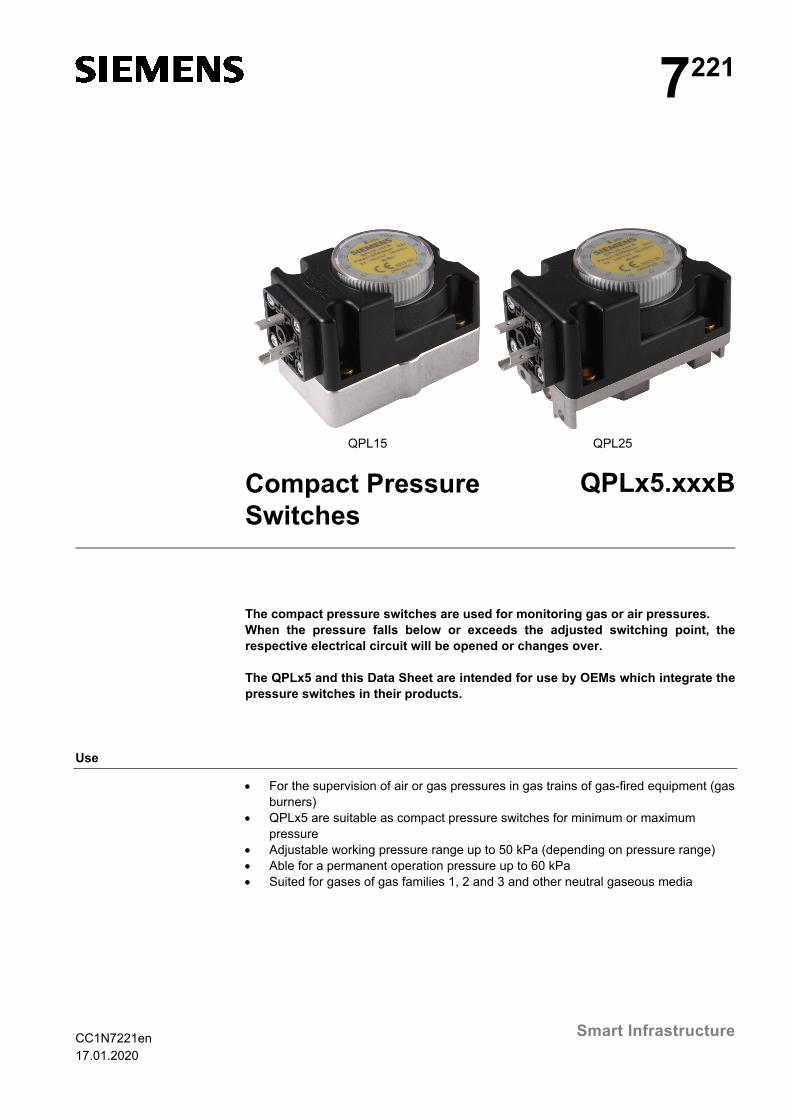
QPL15 QPL25 Compact Pressure
Switches QPLx5.xxxB
The compact pressure switches are used for monitoring gas or air pressures. When the pressure falls below or exceeds the adjusted switching point, the respective electrical circuit will be opened or changes over. The QPLx5 and this Data Sheet are intended for use by OEMs which integrate the pressure switches in their products.
Use
For the supervision of air or gas pressures in gas trains of gas-fired equipment (gas burners)
QPLx5 are suitable as compact pressure switches for minimum or maximum pressure
Adjustable working pressure range up to 50 kPa (depending on pressure range) Able for a permanent operation pressure up to 60 kPa Suited for gases of gas families 1, 2 and 3 and other neutral gaseous media
2/11
Smart Infrastructure CC1N7221en 17.01.2020
Warning notes
To avoid injury to persons, damage to property or the environment, the following warning notes must be observed! Do not open, interfere with or modify the compact pressure switch! All activities (mounting, installation and service work, etc.) must be performed by
authorized staff Before making any wiring changes in the connection area, completely isolate the
unit from the mains supply (all-polar disconnection). Ensure that the plant cannot be inadvertently switched on again and that it is indeed dead. If not disconnected, there is a risk of electric shock hazard
Fall or shock can adversely affect the safety functions. Such units must not be put into operation, even if they do not exhibit any damage
Do not use the QPLx5 in inflammable or explosive gas atmospheres Before using QPLx5 read the Data Sheet. The QPLx5 must be installed in
accordance with applicable regulations
Engineering notes
To set the required switching point, remove the cover from the pressure switch and turn the setting knob clockwise to increase the set value, or counterclockwise to decrease it (see scale under «Dimensions»). Replace the cover and secure it to prevent tampering.
Particularly important! The switching point must be checked in the application against the actual intended switching pressure applied and adjusted if necessary. The direction of the pressure rise / pressure drop must be observed here.
Setting the switching point
3/11
Smart Infrastructure CC1N7221en 17.01.2020
Mounting notes
Ensure that the relevant national safety regulations are complied with By check piping connections ensure that there are no leaks To prevent the pressure connection from being blocked by contamination on the
plant, a suitable preventive precaution must be used Example: Installation of a fine mesh or filter
The QPLx5 can be mounted either horizontally or vertically, but not in a suspended position (scale must not pointing downward)
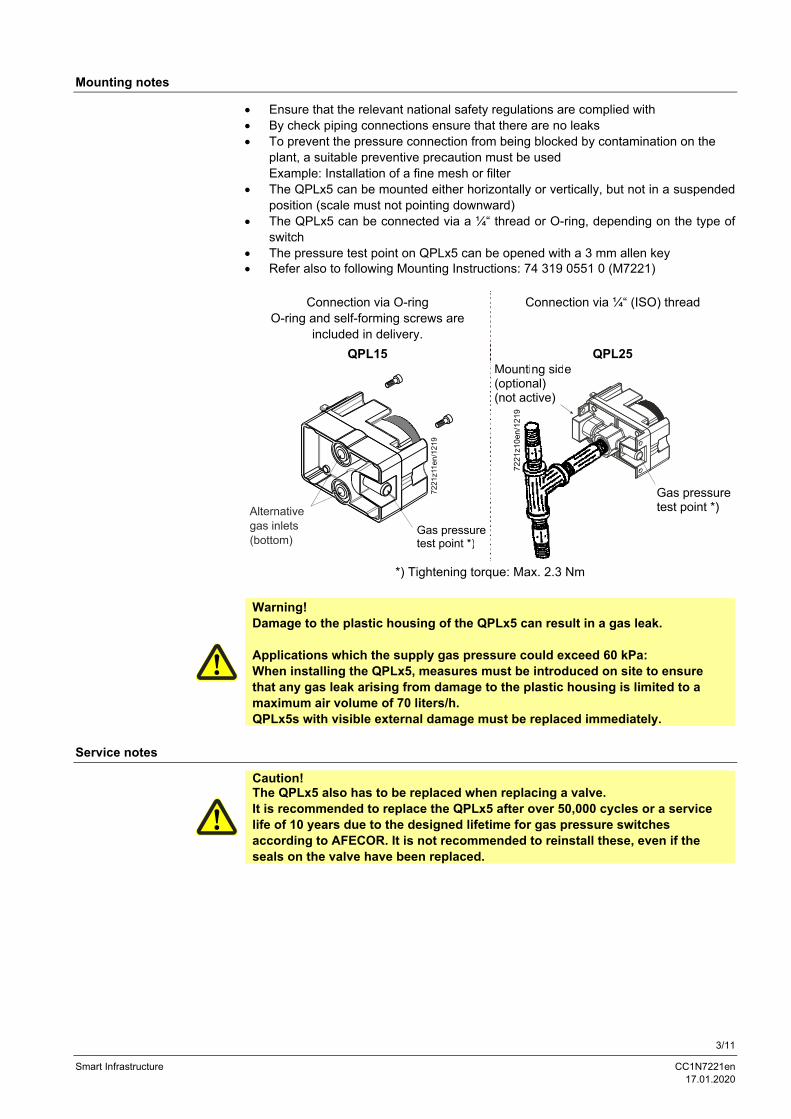
The QPLx5 can be connected via a ¼“ thread or O-ring, depending on the type of switch
The pressure test point on QPLx5 can be opened with a 3 mm allen key Refer also to following Mounting Instructions: 74 319 0551 0 (M7221)
Connection via O-ring O-ring and self-forming screws are
included in delivery.
Connection via ¼“ (ISO) thread
QPL15 QPL25
*) Tightening torque: Max. 2.3 Nm
Warning! Damage to the plastic housing of the QPLx5 can result in a gas leak. Applications which the supply gas pressure could exceed 60 kPa: When installing the QPLx5, measures must be introduced on site to ensure that any gas leak arising from damage to the plastic housing is limited to a maximum air volume of 70 liters/h. QPLx5s with visible external damage must be replaced immediately.
Service notes
Caution! The QPLx5 also has to be replaced when replacing a valve. It is recommended to replace the QPLx5 after over 50,000 cycles or a service life of 10 years due to the designed lifetime for gas pressure switches according to AFECOR. It is not recommended to reinstall these, even if the seals on the valve have been replaced.
4/11
Smart Infrastructure CC1N7221en 17.01.2020
Standards and certificates
Applied directives: Low-voltage directive 2014/35/EC
Gas Appliances Regulation EU/2016/426 Compliance with the regulations of the applied directives is verified by the adherence to the following standards / regulations: Pressure sensing devices for gas burners and gas burning
appliances DIN EN 1854
Automatic electrical controls Part 2-6: Particular requirements for automatic electrical pressure sensing controls including mechanical requirements
DIN EN 60730-2-6
The relevant valid edition of the standards can be found in the declaration of conformity!
EAC Conformity mark (Eurasian Conformity mark)
China RoHS Hazardous substances table: http://www.siemens.com/download?A6V10883536
http://www.szutest.cz
Lifetime
The compact pressure switch has a designed lifetime* of 50,000 burner startup cycles when using gases in accordance with EN 437 (or specification G260), which, under normal operating conditions in heating mode, correspond to approx. 10 years of usage (starting from the production date given on the type field). This is based on the endurance tests specified in the standard EN 1854. A summary of the conditions has been published by the European Control Manufacturers Association (Afecor) (www.afecor.org). The designed lifetime is based on use of the compact pressure switch according to the manufacturer’s data sheet. After reaching the designed lifetime in terms of the number of burner startup cycles, or after the corresponding usage time, the compact pressure switch must be replaced by authorized personnel. * The designed lifetime is not the warranty time specified in the Terms of Delivery.
Disposal notes
The unit contains electrical and electronic components and must not be disposed of together with domestic waste. Local and currently valid legislation must be observed.
5/11
Smart Infrastructure CC1N7221en 17.01.2020
Mechanical design
Housing made of durable plastic with die-cast aluminum base Adjustable switching point Automatic reset The switching point (setpoint) of the QPLx5 is to be set with the adjusting knob located under the securing cover.
Type summary
When ordering, please give type reference according to Type summary.
Note! The QPLx5.xxxB listed here replace the previous version QPLx5.xxx.
QPLx5 with automatic reset:
Pressure range ¼“ connection O-ring connection
Type Article no. Type Article no.
0.1…0.3 kPa QPL25.003B S55722-S101-A100 QPL15.003B S55722-S106-A100
0.2…1 kPa QPL25.010B S55722-S102-A100 QPL15.010B S55722-S107-A100
0.5…5 kPa QPL25.050B S55722-S103-A100 QPL15.050B S55722-S108-A100
0.5…15 kPa QPL25.150B S55722-S104-A100 QPL15.150B S55722-S109-A100
10…50 kPa QPL25.500B S55722-S105-A100 QPL15.500B S55722-S110-A100
Accessories
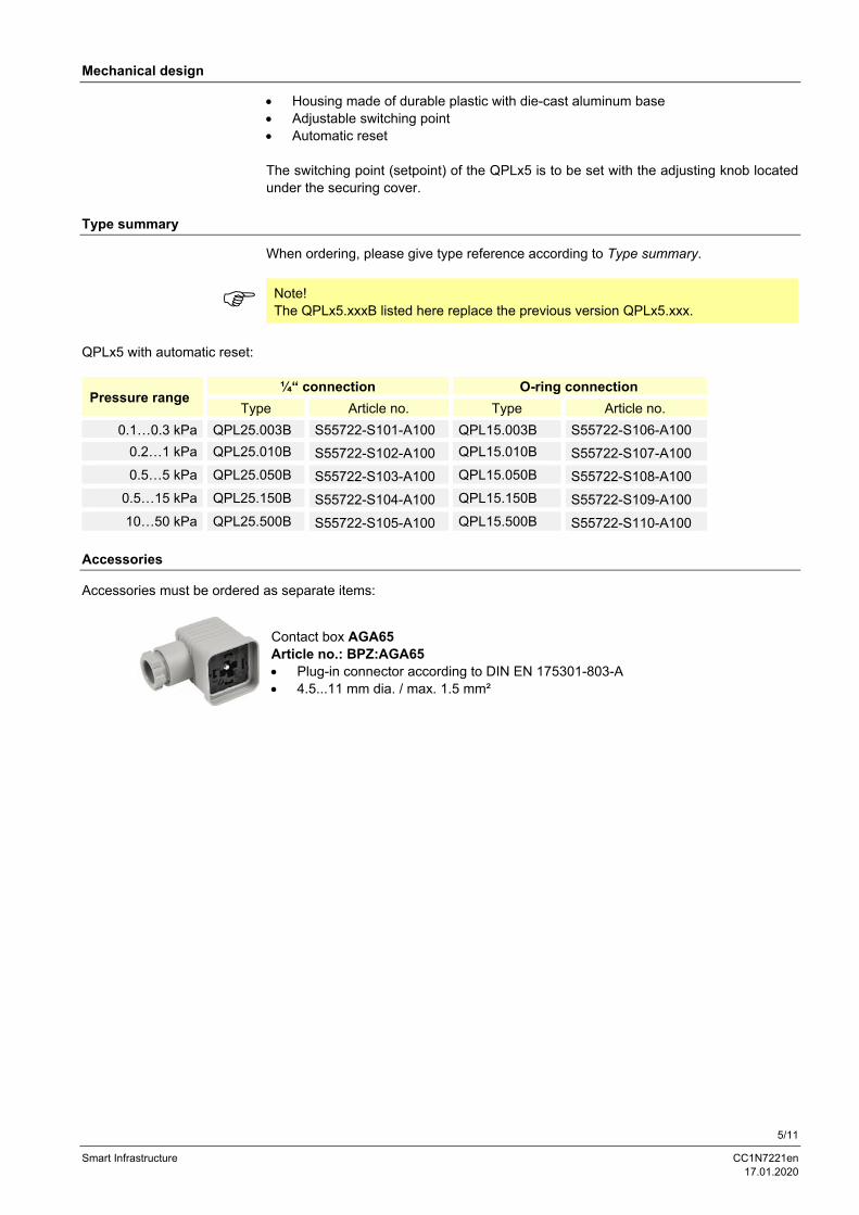
Accessories must be ordered as separate items:
Contact box AGA65 Article no.: BPZ:AGA65 Plug-in connector according to DIN EN 175301-803-A 4.5...11 mm dia. / max. 1.5 mm²
6/11
Smart Infrastructure CC1N7221en 17.01.2020
Technical data
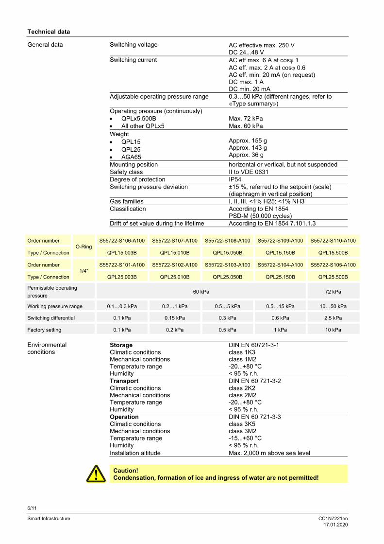
Switching voltage AC effective max. 250 V DC 24...48 V
Switching current AC eff max. 6 A at cos 1 AC eff. max. 2 A at cos 0.6 AC eff. min. 20 mA (on request) DC max. 1 A DC min. 20 mA
Adjustable operating pressure range 0.3…50 kPa (different ranges, refer to «Type summary»)
Operating pressure (continuously) QPLx5.500B Max. 72 kPa All other QPLx5 Max. 60 kPa Weight QPL15 QPL25 AGA65
Approx. 155 g Approx. 143 g Approx. 36 g
Mounting position horizontal or vertical, but not suspended Safety class II to VDE 0631 Degree of protection IP54 Switching pressure deviation ±15 %, referred to the setpoint (scale)
(diaphragm in vertical position) Gas families I, II, III, <1% H25; <1% NH3 Classification According to EN 1854
PSD-M (50,000 cycles) Drift of set value during the lifetime According to EN 1854 7.101.1.3
Order number O-Ring
S55722-S106-A100 S55722-S107-A100 S55722-S108-A100 S55722-S109-A100 S55722-S110-A100
Type / Connection QPL15.003B QPL15.010B QPL15.050B QPL15.150B QPL15.500B
Order number 1/4"
S55722-S101-A100 S55722-S102-A100 S55722-S103-A100 S55722-S104-A100 S55722-S105-A100
Type / Connection QPL25.003B QPL25.010B QPL25.050B QPL25.150B QPL25.500B
Permissible operating
pressure 60 kPa 72 kPa
Working pressure range 0.1…0.3 kPa 0.2…1 kPa 0.5…5 kPa 0.5…15 kPa 10…50 kPa
Switching differential 0.1 kPa 0.15 kPa 0.3 kPa 0.6 kPa 2.5 kPa
Factory setting 0.1 kPa 0.2 kPa 0.5 kPa 1 kPa 10 kPa
Storage DIN EN 60721-3-1 Climatic conditions class 1K3 Mechanical conditions class 1M2 Temperature range -20...+80 °C Humidity < 95 % r.h. Transport DIN EN 60 721-3-2 Climatic conditions class 2K2 Mechanical conditions class 2M2 Temperature range -20...+80 °C Humidity < 95 % r.h. Operation DIN EN 60 721-3-3 Climatic conditions class 3K5 Mechanical conditions class 3M2 Temperature range -15...+60 °C Humidity < 95 % r.h. Installation altitude Max. 2,000 m above sea level
Caution! Condensation, formation of ice and ingress of water are not permitted!
General data
Environmental conditions
7/11
Smart Infrastructure CC1N7221en 17.01.2020
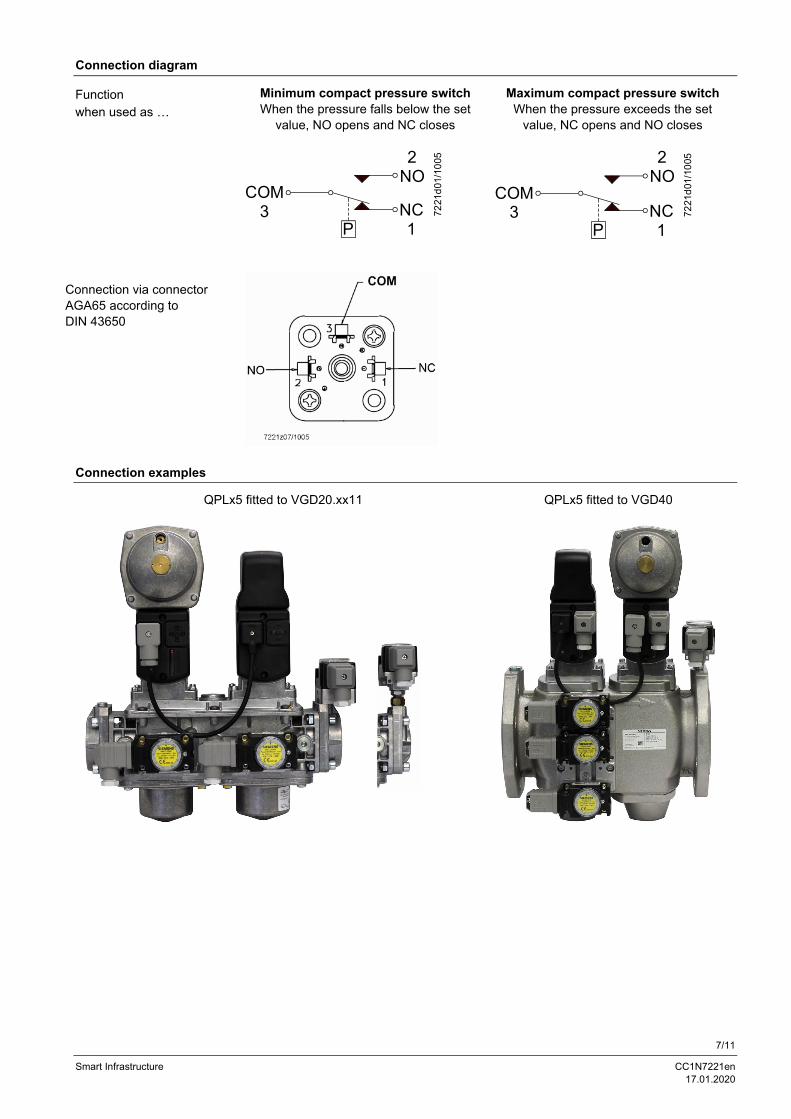
Connection diagram
Minimum compact pressure switch When the pressure falls below the set
value, NO opens and NC closes
Maximum compact pressure switch When the pressure exceeds the set
value, NC opens and NO closes
P
COM3
2NO
NC1
7221
d01
/10
05
P
COM3
2NO
NC1
7221
d01
/10
05
Connection examples
QPLx5 fitted to VGD20.xx11
QPLx5 fitted to VGD40
Function when used as …
Connection via connector AGA65 according to DIN 43650
8/11
Smart Infrastructure CC1N7221en 17.01.2020
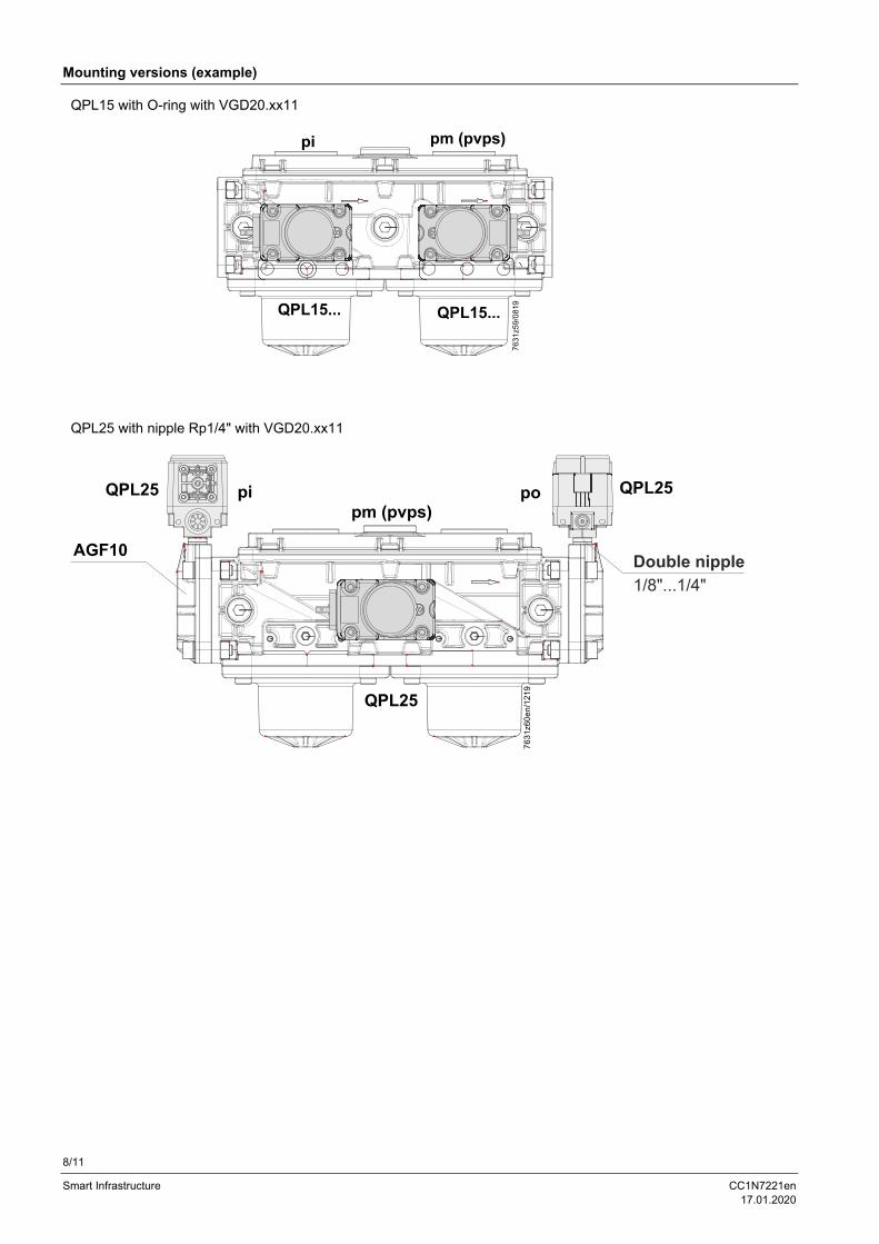
Mounting versions (example)
QPL15 with O-ring with VGD20.xx11
QPL25 with nipple Rp1/4" with VGD20.xx11
9/11
Smart Infrastructure CC1N7221en 17.01.2020
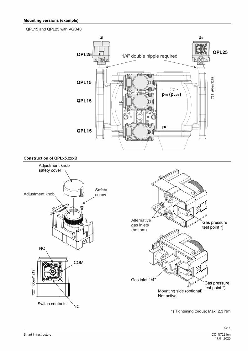
Mounting versions (example)
QPL15 and QPL25 with VGD40
Construction of QPLx5.xxxB
*) Tightening torque: Max. 2.3 Nm
10/11
Smart Infrastructure CC1N7221en 17.01.2020
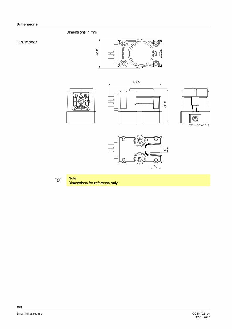
Dimensions
Dimensions in mm
Note! Dimensions for reference only
QPL15.xxxB
11/11
Smart Infrastructure CC1N7221en 17.01.2020
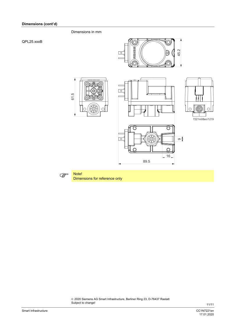
Dimensions (cont’d)
Dimensions in mm
Note! Dimensions for reference only
QPL25.xxxB
2020 Siemens AG Smart Infrastructure, Berliner Ring 23, D-76437 Rastatt Subject to change!