Embed Size (px)
Citation preview

QRP Transceiver Projects
Jim Spikes, N4KH
21 April 2012

Evolution of 40 Meter CW Transceiver
• R1 high performance direct conversion receiver• Rockmite 40 – performance left something to be
desired• Goal: Build a real homebrew transceiver for 40 CW,
consisting of:– R1 DC receiver and a proven VFO circuit– 3 stage MKII 5W+ transmitter– Universal VFO – Suitable for R1 and its successor,
the Mini-R2– Norcal Keyer– Upgrade to Mini-R2 receiver

Receiver (R1)• Good performance
• Very low distortion audio amp
• Built with 3Khz filter
• No provision for removing audio image/opposite sideband
• No AGC
“High-Performance Direct-Conversion Receivers” by Rick Campbell, KK7B, QST, August 1992
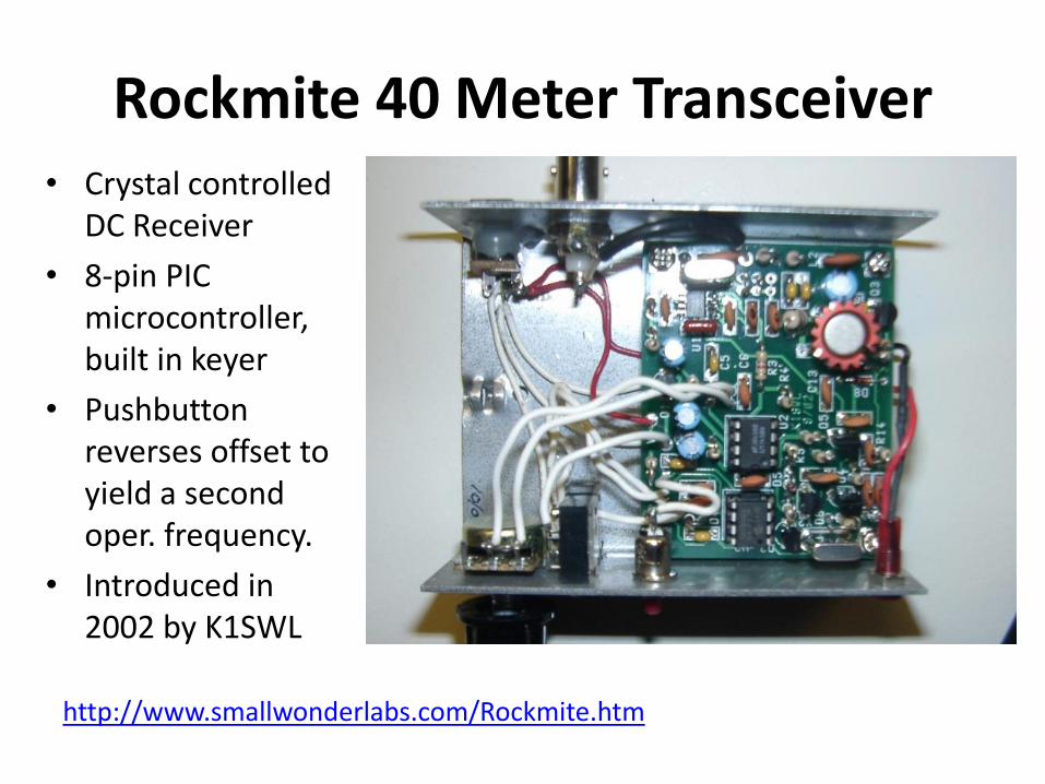
Rockmite 40 Meter Transceiver
http://www.smallwonderlabs.com/Rockmite.htm
• Crystal controlled DC Receiver
• 8-pin PIC microcontroller, built in keyer
• Pushbutton reverses offset to yield a second oper. frequency.
• Introduced in 2002 by K1SWL
Some Desired Features
• 40 meter CW band
• 5+ watts output
• Smooth T/R switching/semi break-in keying
• Built-in keyer
• Receiver incremental tuning (RIT)
• Good performance (not too worried about parts count or DC power consumption)
• Enough audio output for small speaker
• Portable
MKII Transmitter
*Obsolete, check with Bill Kelsey, N8ET at http://www.kangaus.com/
• 3 stage design, up to ~7.5 watts output if desired (or a bit more?), depending on supply voltage and drive setting
• Automatic T/R switching for use with a receiver
• Side tone oscillator
• Spot circuit
• 2N3904 crystal oscillator/VXO, inexpensive 2SC5739* driver and power amp
• Common parts for T/R switching and side-tone oscillator
• See Wes’ website for notes on MKII transmitter http://w7zoi.net/mark2.html
“An Updated Universal QRP Transmitter” by Wes Hayward, W7ZOI, QST, April 2006
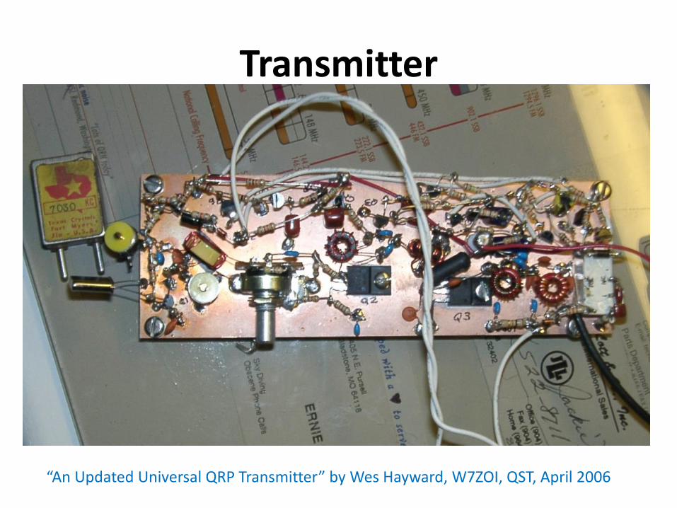
Transmitter
“An Updated Universal QRP Transmitter” by Wes Hayward, W7ZOI, QST, April 2006
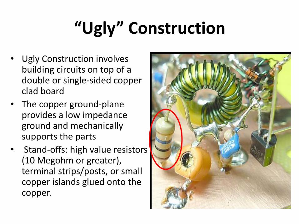
“Ugly” Construction
• Ugly Construction involves building circuits on top of a double or single-sided copper clad board
• The copper ground-plane provides a low impedance ground and mechanically supports the parts
• Stand-offs: high value resistors (10 Megohm or greater), terminal strips/posts, or small copper islands glued onto the copper.

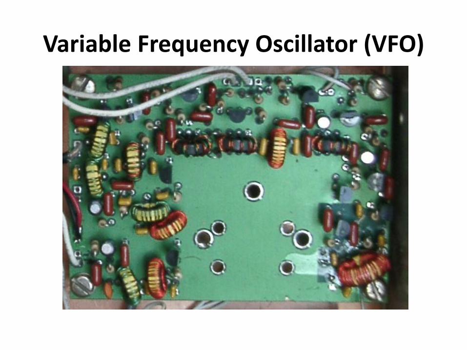
• Universal VFO (UVFO) design (KK7B)
• ~60Khz tuning range (bottom end of 40M)
• I and Q outputs for a receiver
• Single output provided to drive a transmitter.
• RIT built in.
• Variable capacitor with reduction drive
Variable Frequency Oscillator (VFO)
http://www.kangaus.com/
Variable Frequency Oscillator (VFO)

Norcal Memory Keyer
http://www.norcalqrp.org/nckeyer.htm (now retired)
• PIC12F6293 microcontroller (pre-programmed)• Three 40-character memories• Iambic, straight key and bug mode; beacon modes• Variable speed control via paddles (option for
potentiometer control if desired).• 7-to-18 volt input power range with 5V regulator built
in• Side-tone from keyer is injected into the audio circuit• “FB” sent by the keyer at power up through the
sidetone if functioning correctly.

Output Transistor (to key rig)
5V Reg. Keyer Chip

Keys Used PAR (press and release) PAH (press and hold)
Mem switch Send memory 3 Record memory 3, O? Beacons: BE and BA
Mem + dit Send speed Paddle set of speed, pot options, main menu
Mem + dah Send memory 2 Record memory 2: M?
Mem + both Send memory 1 Record memory 1: T?
CW Menu Item Pressing a dit Pressing a dah
Memory + Dit Menu (PAR mem to advance to the next menu)
S Speed set from paddle Increase speed 1 wpm Decrease speed 1 wpm
P Pot / paddle speed control Selects pot speed control Selects paddle speed control
C Calibrate pot speed control Enters the calibration routine Restores default pot calibration
B Bug / straight key mode Enables bug mode (dah = key) Disables bug mode (default)
A Iambic mode A or B Enables iambic mode A Enables mode B (default)
R Reverse paddle mode Reverse dit and dah switches Returns dit and dah to normal
AU Autospace on / off Turns on character autospace Turns off autospace (default)
Memory + Dah Menu (PAR mem to exit)
M? Record memory 2 Records a dit Records a dah
Memory Switch Menu (PAR mem to advance to next menu)
O? Record memory 3 Records a dit Records a dah
BE Beacon mode - sends mem 1 Starts the beacon going Exits the menu
BA Beacon alternate mode Selects alternate beacon sends
of mem 1 and mem 2
Selects send of mem 1 only
(default)
ST Side tone on/off Turns off the side tone Turns the side tone on
Memory + Both Menu (PAR mem to exit)
T? Record memory 1 Records a dit Records a dah

Transceiver Enclosure
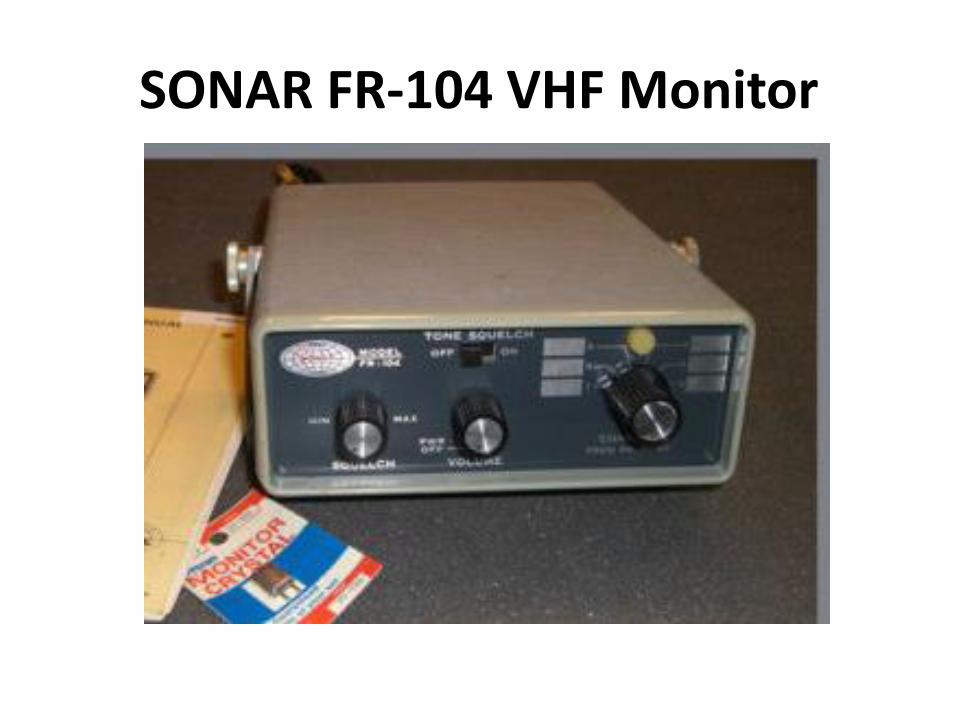
SONAR FR-104 VHF Monitor
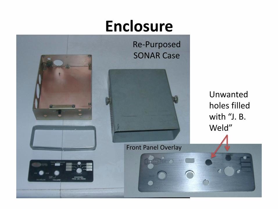
Enclosure
Unwanted holes filled with “J. B. Weld”
Re-PurposedSONAR Case
Front Panel Overlay
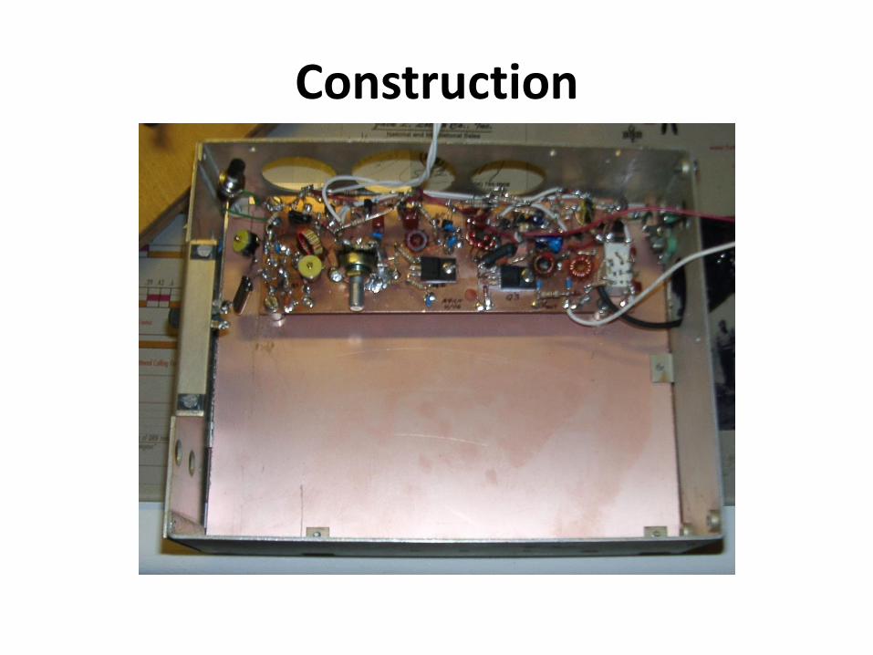
Construction

Internal Layout
R1 ReceiverVFO
Transmitter Keyer

Front Panel

Receiver Mini-R2
“A Small High Performance CW Transceiver” by Rick Campbell, QST, November 1995
• DC Phasing Receiver (single signal)
• Based on R1, successor to original R2
• Audio sufficient for headphones or small speaker
• Slightly better performance than R2 and R1

On The Air• Contacts
– V31WA Belize
– SC8N Sweden
– CS95A Madeira Is.
– P40ADI Aruba
– OK5W Czech Rep.
– OM2VL Slovak Rep.
– HB9LCW Switzerland
– Numerous states (incl. FL, CA, WA, CA )

Possible Improvements
• Adjustable T-R delay
• Selectable bandwidth audio filter (Wide/Narrow)
• Switch for second tuning range
• Internal speaker
• Louder spot signal
• 30, 20 or 15 Meter version
• ??
Build Something!
• Not as difficult as you think!
• Many excellent published designs (QST, CQ, ARRL Handbook, Web)
• “Bag” kits avoid gathering of parts
• Larger projects (e.g. receiver, transceiver) can usually be broken down into modules
• Learn by doing
• Loads of fun to put it to work in your station