Embed Size (px)
Citation preview
Our energy working for you.™
www.cumminsgdrive.com
2009|Cummins G-Drive Engines|Specifications Subject to Change Without Notice|Cummins is a registered trademark of Cummins Inc. (11/09) (GDSS151)
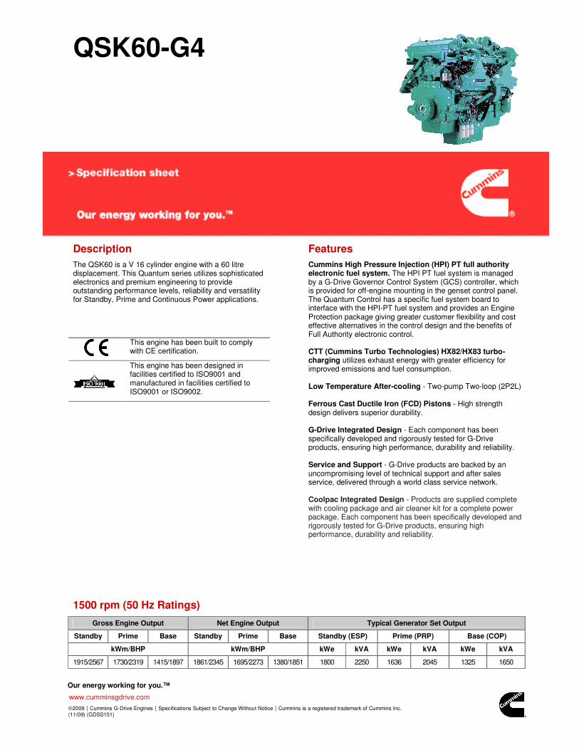
QSK60-G4
Description
The QSK60 is a V 16 cylinder engine with a 60 litre displacement. This Quantum series utilizes sophisticated electronics and premium engineering to provide outstanding performance levels, reliability and versatility for Standby, Prime and Continuous Power applications.
This engine has been built to comply with CE certification.
This engine has been designed in facilities certified to ISO9001 and manufactured in facilities certified to ISO9001 or ISO9002.
Features
Cummins High Pressure Injection (HPI) PT full authority electronic fuel system. The HPI PT fuel system is managed by a G-Drive Governor Control System (GCS) controller, which is provided for off-engine mounting in the genset control panel. The Quantum Control has a specific fuel system board to interface with the HPI-PT fuel system and provides an Engine Protection package giving greater customer flexibility and cost effective alternatives in the control design and the benefits of Full Authority electronic control. CTT (Cummins Turbo Technologies) HX82/HX83 turbo-charging utilizes exhaust energy with greater efficiency for improved emissions and fuel consumption. Low Temperature After-cooling - Two-pump Two-loop (2P2L) Ferrous Cast Ductile Iron (FCD) Pistons - High strength design delivers superior durability. G-Drive Integrated Design - Each component has been specifically developed and rigorously tested for G-Drive products, ensuring high performance, durability and reliability. Service and Support - G-Drive products are backed by an uncompromising level of technical support and after sales service, delivered through a world class service network. Coolpac Integrated Design - Products are supplied complete with cooling package and air cleaner kit for a complete power package. Each component has been specifically developed and rigorously tested for G-Drive products, ensuring high performance, durability and reliability.
1500 rpm (50 Hz Ratings)
Gross Engine Output Net Engine Output Typical Generator Set Output
Standby Prime Base Standby Prime Base Standby (ESP) Prime (PRP) Base (COP)
kWm/BHP kWm/BHP kWe kVA kWe kVA kWe kVA
1915/2567 1730/2319 1415/1897 1861/2345 1695/2273 1380/1851 1800 2250 1636 2045 1325 1650
Our energy working for you.™
www.cumminsgdrive.com
2009|Cummins G-Drive Engines|Specifications Subject to Change Without Notice|Cummins is a registered trademark of Cummins Inc. (11/09) (GDSS151)
General Engine Data Ratings Definitions
Type 4 cycle, Turbocharged, After-cooled
Bore mm 159
Stroke mm 190
Displacement Litre 60.2
Cylinder Block Cast iron, 16 cylinder
Battery Charging Alternator 55A
Starting Voltage 24V
Fuel System Direct injection Cummins HPI
Fuel Filter Spin on fuel filters with water separator
Lube Oil Filter Type(s) Spin on full flow filter
Lube Oil Capacity (l) 280
Flywheel Dimensions SAE 0
Coolpac Performance Data
Cooling System Design 2 pump - 2 loop
Coolant Ratio 50% ethylene glycol; 50% water
Coolant Capacity (l) 242.0
Limiting Ambient Temp.** 54.9
Fan Power 45.0
Cooling System Air Flow (m3/s)** 29.6
Air Cleaner Type Dry replaceable element with restriction indicator ** @ 13 mm H
20
Emergency Standby Power (ESP): Applicable for supplying power to varying electrical load for the duration of power interruption of a reliable utility source. Emergency Standby Power (ESP) is in accordance with ISO 8528. Fuel Stop power in accordance with ISO 3046, AS 2789, DIN 6271 and BS 5514. Limited-Time Running Power (LTP): Applicable for supplying power to a constant electrical load for limited hours. Limited-Time Running Power (LTP) is in accordance with ISO 8528. Prime Power (PRP): Applicable for supplying power to varying electrical load for unlimited hours. Prime Power (PRP) is in accordance with ISO 8528. Ten percent overload capability is available in accordance with ISO 3046, AS 2789, DIN 6271 and BS 5514. Base Load (Continuous) Power (COP): Applicable for supplying power continuously to a constant electrical load for unlimited hours. Continuous Power (COP) in accordance with ISO 8528, ISO 3046, AS 2789, DIN6271 and BS 5514.
Weight & Dimensions
Length Width Height Weight (dry)
mm mm mm kg
4123 2494 3296 9685
Fuel Consumption 1500 (50 Hz)
% kWm BHP L/ph US gal/ph
Standby Power
100 1915 2567 437 115.3
Prime Power
100 1730 2319 394 103.9
75 1298 1739 291 76.9
50 865 1160 200 52.7
25 433 580 114 30.1
Continuous Power
100 1415 1897 320 84.4
Cummins G-Drive Engines
Asia Pacific 10 Toh Guan Road #07-01 TT International Tradepark Singapore 608838 Phone 65 6417 2388 Fax 65 6417 2399
Europe, CIS, Middle East and Africa Manston Park Columbus Ave Manston Ramsgate Kent CT12 5BF. UK Phone 44 1843 255000 Fax 44 1843 255902
Latin America Rua Jati, 310, Cumbica Guarulhos, SP 07180-900 Brazil Phone 55 11 2186 4552 Fax 55 11 2186 4729
Mexico Cummins S. de R.L. de C.V. Eje 122 No. 200 Zona Industrial San Luis Potosí, S.L.P. 78090 Mexico Phone 52 444 870 6700 Fax 52 444 870 6811
North America 1400 73rd Avenue N.E. Minneapolis, MN 55432 USA Phone 1 763 574 5000 USA Toll-free 1 877 769 7669 Fax 1 763 574 5298
PI734F - Technical Data Sheet
PI734FSPECIFICATIONS & OPTIONS
STANDARDS
Newage Stamford industrial generators meet the requirements of BS EN 60034 and the relevant sections of other national and international standards such as BS5000, VDE 0530, NEMA MG1-32, IEC60034, CSA C22.2-100, AS1359.Other standards and certifications can be considered on request.
DESCRIPTION
The STAMFORD PI range of synchronous ac generators are brushless with a rotating field. They are separately excited by the STAMFORD Permanent Magnet Generator (PMG). This is a shaft mounted, high frequency, pilot exciter which provides a constant supply of clean power via the Automatic Voltage Regulator (AVR) to the main exciter. The main exciter output is fed to the main rotor, through a full wave bridge rectifier, protected by surge suppression. VOLTAGE REGULATORS
The PI range generators, complete with a PMG, are available with one of two AVRs. Each AVR has soft start voltage build up and built in protection against sustained over-excitation, which will de-excite the generator after a minimum of 8 seconds. Underspeed protection (UFRO) is also provided on both AVRs. The UFRO will reduce the generator output voltage proportional to the speed of the generator below a pre-settable level.
The MX341 AVR is two phase sensed with a voltage regulation of ± 1 %. (see the note on regulation).
The MX321 AVR is 3 phase rms sensed with a voltage regulation of 0.5% rms (see the note on regulation). The UFRO circuit has adjustable slope and dwell for controlled recovery from step loads. An over voltage protection circuit will shutdown the output device of the AVR, it can also trip an optional excitation circuit breaker if required. As an option, short circuit current limiting is available with the addition of current transformers.
Both the MX341 and the MX321 need a generator mounted current transformer to provide quadrature droop characteristics for load sharing during parallel operation. Provision is also made for the connection of the STAMFORD power factor controller, for embedded applications, and a remote voltage trimmer.
WINDINGS & ELECTRICAL PERFORMANCE
All generator stators are wound to 2/3 pitch. This eliminates triplen (3rd, 9th, 15th …) harmonics on the voltage waveform and is found to be the optimum design for trouble-free supply of non-linear loads. The 2/3 pitch design avoids excessive neutral currents sometimes seen with higher winding pitches. A fully connected damper winding reduces oscillations during paralleling. This winding, with the 2/3 pitch and carefully selected pole and tooth designs, ensures very low levels of voltage waveform distortion.
TERMINALS & TERMINAL BOX
Standard generators feature a main stator with 6 ends brought out to the terminals, which are mounted on the frame at the non-drive end of the generator. A sheet steel terminal box contains the AVR and provides ample space for the customers' wiring and gland arrangements. It has removable panels for easy access.
SHAFT & KEYS
All generator rotors are dynamically balanced to better than BS6861:Part 1 Grade 2.5 for minimum vibration in operation. Two bearing generators are balanced with a half key.
INSULATION/IMPREGNATION
The insulation system is class 'H', and meets the requirements of UL1446.All wound components are impregnated with materials and processes designed specifically to provide the high build required for static windings and the high mechanical strength required for rotating components.
QUALITY ASSURANCE
Generators are manufactured using production procedures having a quality assurance level to BS EN ISO 9001.
NOTE ON REGULATIONThe stated voltage regulation may not be maintained in the presence of certain radio transmitted signals. Any change in performance will fall within the limits of Criteria 'B' of EN 61000-6-2:2001. At no time will the steady-state voltage regulation exceed 2%.
Note: Continuous development of our products entitles us to change specification details without notice, therefore they must not be regarded as binding.
Front cover drawing is typical of the product range.
2
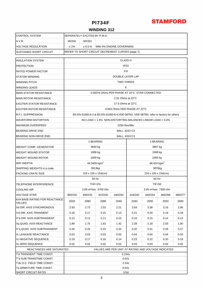
CONTROL SYSTEM SEPARATELY EXCITED BY P.M.G.
A.V.R. MX341 MX321
VOLTAGE REGULATION ± 1% ± 0.5 % With 4% ENGINE GOVERNING
SUSTAINED SHORT CIRCUIT
INSULATION SYSTEM
PROTECTION
RATED POWER FACTOR
STATOR WINDING
WINDING PITCH
WINDING LEADS
MAIN STATOR RESISTANCE
MAIN ROTOR RESISTANCE
EXCITER STATOR RESISTANCE
EXCITER ROTOR RESISTANCE
R.F.I. SUPPRESSION BS EN 61000-6-2 & BS EN 61000-6-4,VDE 0875G, VDE 0875N. refer to factory for others
WAVEFORM DISTORTION NO LOAD < 1.5% NON-DISTORTING BALANCED LINEAR LOAD < 5.0%
MAXIMUM OVERSPEED 2250 Rev/Min
BEARING DRIVE END BALL. 6232 C3
BEARING NON-DRIVE END BALL. 6319 C3
1 BEARING 2 BEARING
WEIGHT COMP. GENERATOR
WEIGHT WOUND STATOR
WEIGHT WOUND ROTOR
WR² INERTIA
SHIPPING WEIGHTS in a crate
PACKING CRATE SIZE
TELEPHONE INTERFERENCE
COOLING AIR
VOLTAGE STAR 380/220 400/231 415/240 440/254 416/240 440/254 460/266 480/277
kVA BASE RATING FOR REACTANCE VALUES 2020 2080 2080 2040 2340 2500 2550 2600
Xd DIR. AXIS SYNCHRONOUS 2.93 2.73 2.53 2.21 3.54 3.38 3.16 2.96
X'd DIR. AXIS TRANSIENT 0.18 0.17 0.15 0.13 0.21 0.20 0.19 0.18
X''d DIR. AXIS SUBTRANSIENT 0.13 0.12 0.11 0.10 0.16 0.15 0.14 0.13
Xq QUAD. AXIS REACTANCE 1.89 1.75 1.63 1.42 2.28 2.18 2.03 1.90
X''q QUAD. AXIS SUBTRANSIENT 0.26 0.25 0.23 0.20 0.32 0.31 0.29 0.27
XL LEAKAGE REACTANCE 0.03 0.03 0.03 0.03 0.04 0.04 0.04 0.03
X2 NEGATIVE SEQUENCE 0.19 0.17 0.16 0.14 0.23 0.22 0.20 0.19
X0 ZERO SEQUENCE 0.02 0.02 0.02 0.02 0.03 0.03 0.02 0.02
REACTANCES ARE SATURATED VALUES ARE PER UNIT AT RATING AND VOLTAGE INDICATED
T'd TRANSIENT TIME CONST. 0.154sT''d SUB-TRANSTIME CONST. 0.02sT'do O.C. FIELD TIME CONST. 2.54s
Ta ARMATURE TIME CONST. 0.02s
SHORT CIRCUIT RATIO 1/Xd
REFER TO SHORT CIRCUIT DECREMENT CURVES (page 7)
WINDING 312
DOUBLE LAYER LAP
2.31 Ohms at 22°C
0.8
IP23
CLASS H
0.00076 Ohms PER PHASE AT 22°C STAR CONNECTED
6
TWO THIRDS
PI734F
2.69 m³/sec 5700 cfm 3.45 m³/sec 7300 cfm
50 Hz
THF<2%
60 Hz
TIF<50
3807 kg
48.424 kgm2
216 x 105 x 154(cm)
1565 kg1609 kg
216 x 105 x 154(cm)
49.3409 kgm2
3913kg 3876kg
1908 kg
3840 kg
1908 kg
17.5 Ohms at 22°C
0.063 Ohms PER PHASE AT 22°C
3
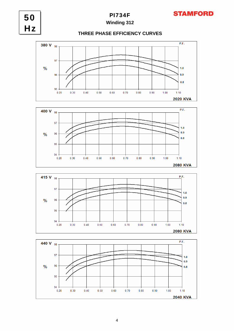
Winding 312PI734F
THREE PHASE EFFICIENCY CURVES
50Hz
4
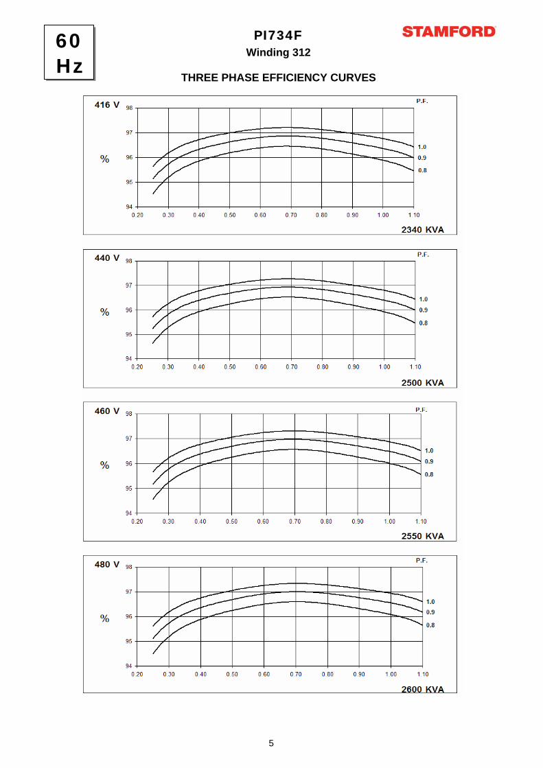
Winding 312PI734F
THREE PHASE EFFICIENCY CURVES
60Hz
5
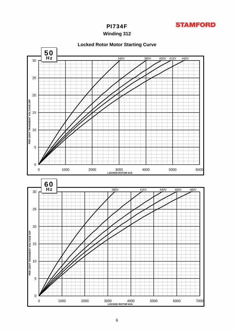
PI734FWinding 312
Locked Rotor Motor Starting Curve
0
5
10
15
20
25
30
0 1000 2000 3000 4000 5000 6000 7000LOCKED ROTOR kVA
PER
CEN
T TR
AN
SIEN
T VO
LTA
GE
DIP
.
380V 416V 440V 460V 480V
0
5
10
15
20
25
30
0 1000 2000 3000 4000 5000 6000LOCKED ROTOR kVA
PER
CEN
T TR
AN
SIEN
T VO
LTA
GE
DIP
.
346V 380V 400V 415V 440V 50Hz
60Hz
6
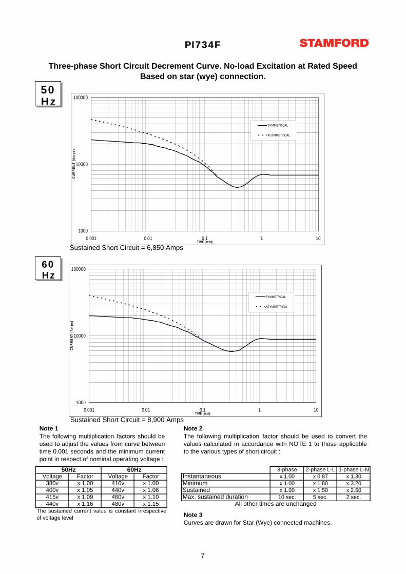
3-phase 2-phase L-L 1-phase L-NVoltage Factor Voltage Factor x 1.00 x 0.87 x 1.30
380v x 1.00 416v x 1.00 x 1.00 x 1.80 x 3.20400v x 1.05 440v x 1.06 x 1.00 x 1.50 x 2.50415v x 1.09 460v x 1.10 10 sec. 5 sec. 2 sec.440v x 1.16 480v x 1.15
50Hz 60Hz
PI734F
The sustained current value is constant irrespectiveof voltage level
Three-phase Short Circuit Decrement Curve. No-load Excitation at Rated SpeedBased on star (wye) connection.
Max. sustained durationAll other times are unchanged
Instantaneous
SustainedMinimum
Sustained Short Circuit = 6,850 Amps
Sustained Short Circuit = 8,900 AmpsNote 1The following multiplication factors should beused to adjust the values from curve betweentime 0.001 seconds and the minimum currentpoint in respect of nominal operating voltage :
Note 2The following multiplication factor should be used to convert thevalues calculated in accordance with NOTE 1 to those applicableto the various types of short circuit :
Note 3Curves are drawn for Star (Wye) connected machines.
50Hz
60Hz
1000
10000
100000
0.001 0.01 0.1 1 10TIME (secs)
CURR
ENT
(Am
ps)
SYMMETRICAL
ASYMMETRICAL
1000
10000
100000
0.001 0.01 0.1 1 10TIME (secs)
CURR
ENT
(Am
ps)
SYMMETRICAL
ASYMMETRICAL
7
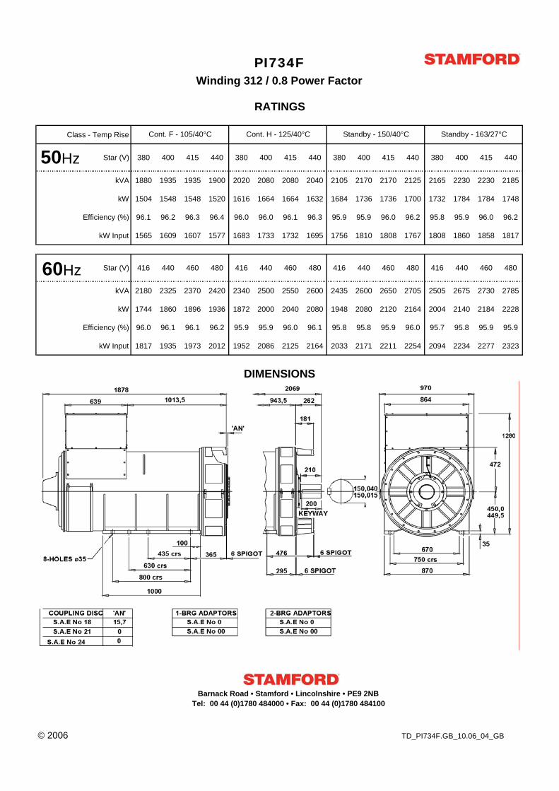
Class - Temp Rise
Star (V) 380 400 415 440 380 400 415 440 380 400 415 440 380 400 415 440
kVA 1880 1935 1935 1900 2020 2080 2080 2040 2105 2170 2170 2125 2165 2230 2230 2185
kW 1504 1548 1548 1520 1616 1664 1664 1632 1684 1736 1736 1700 1732 1784 1784 1748
Efficiency (%) 96.1 96.2 96.3 96.4 96.0 96.0 96.1 96.3 95.9 95.9 96.0 96.2 95.8 95.9 96.0 96.2
kW Input 1565 1609 1607 1577 1683 1733 1732 1695 1756 1810 1808 1767 1808 1860 1858 1817
Star (V) 416 440 460 480 416 440 460 480 416 440 460 480 416 440 460 480
kVA 2180 2325 2370 2420 2340 2500 2550 2600 2435 2600 2650 2705 2505 2675 2730 2785
kW 1744 1860 1896 1936 1872 2000 2040 2080 1948 2080 2120 2164 2004 2140 2184 2228
Efficiency (%) 96.0 96.1 96.1 96.2 95.9 95.9 96.0 96.1 95.8 95.8 95.9 96.0 95.7 95.8 95.9 95.9
kW Input 1817 1935 1973 2012 1952 2086 2125 2164 2033 2171 2211 2254 2094 2234 2277 2323
© 2006 TD_PI734F.GB_10.06_04_GB
DIMENSIONS
PI734F
Cont. F - 105/40°C Cont. H - 125/40°C Standby - 150/40°C Standby - 163/27°C
Winding 312 / 0.8 Power Factor
RATINGS
50Hz
60Hz
Barnack Road • Stamford • Lincolnshire • PE9 2NBTel: 00 44 (0)1780 484000 • Fax: 00 44 (0)1780 484100