Embed Size (px)
Citation preview
Fowee 1 31st Annual AIAA/USU Conference on Small Satellites
SSC17-WK-48
Quad-Thruster FEMTA Micropropulsion System for CubeSat 1-Axis Control
Katherine Fowee, Steven Pugia, Ryan Clay, Matthew Fuehne, Margaret Linker, Anthony Cofer, Alina Alexeenko Purdue University School of Aeronautics & Astronautics
701 W. Stadium Avenue West Lafayette, IN 47907; (765) 496-1864 [email protected]
ABSTRACT
The need for compact, low-power micropropulsion systems to increase the maneuverability and lifespan of CubeSats has increased significantly as nanosat missions have become more ubiquitous and complex. The Film-Evaporation MEMS Tunable Array (FEMTA) thruster is a novel micropropulsion technology that exploits thermally controlled microcapillaries to generate micronewton thrust using liquid water as propellant. Here we present the design and testing of four FEMTA thrusters integrated into a 1U CubeSat prototype with the necessary electronics and an inertial measurement unit sensor to monitor the 1U-quad-thruster FEMTA CubeSat Model’s attitude. The model was tested in the Purdue University High Vacuum Facility’s large vacuum chamber for single-axis control using the FEMTA propulsion system. The experimental data on CubeSat rotation at a slew rate of about 5 deg/sec activated by FEMTA systems with <1 Watt input power show that FEMTA is a viable method for attitude control of CubeSats.
INTRODUCTION
Microsatellites and nanosatellites have become increasingly prevalent, as they present a cost-effective solution for an increasing range of space mission architectures. They offer an opportunity for new missions, such as constellation flying and exploration that their larger counterparts cannot economically achieve. To attain their full potential, small satellites, such as CubeSats, require micropropulsion devices to deliver precise low-thrust impulse bits for scientific, commercial, and military space applications. Onboard micropropulsion would mobilize a satellite to allow for accurate attitude control and precise station keeping of spacecraft constellations. Due to strict mass, power, and volume constraints, microspacecraft present the most challenging requirements for propulsion systems. Several micropropulsion technologies are being developed with the potential for integration in CubeSat missions.
Cold gas systems offer a high degree of simplicity and are one of the most mature options for small spacecraft. They offer limited propulsive capabilities, but provide low impulse bits and compact, lightweight thrusters. A major challenge with cold gas systems is large and heavy storage tanks that lead to bulky systems [1]. Chemical propulsion systems with non-toxic propellants are another potential micropropulsion option. However, this alternative presents technical challenges with available materials and power requirements as many non-toxic propellants are still in development [2].
Several electric propulsion technologies are being developed for small spacecraft. Ion engines are highly efficient when compared to other electric propulsion technologies, reporting the highest specific impulse of small satellite technologies [3]. Despite this increased efficiency, high power consumption greatly increases the mass and volume of these systems. Hall Effect thrusters are a mature technology for large spacecraft and miniaturized systems have been developed [2]. Even with the improvements of cylindrical Hall thrusters over traditional annular thrusters, further reductions in size and power are needed for nanosatellite integration [4,5]. In summary, there have been substantial improvements made in micropropulsion technologies, but further reductions in mass, volume, and power are necessary for integration with small spacecraft.
One potential solution is Film-Evaporating MEMS Tunable Array (FEMTA) thrusters. FEMTA thrusters are microscale nozzles manufactured on silicon wafers via nanofabrication. The thrusters operate by using temperature dependent microscale capillary effects to generate controllable thrust in the range of 6 to 68 micronewtons. The propellant for the FEMTA thrusters is ultra-pure deionized liquid water and the operating mass flow rate is 80 micrograms per second. Early vacuum tests of the thrusters have yielded thrust to power ratios of 230 micronewtons per watt with specific impulse values greater than 80 seconds [6].
Fowee 2 31st Annual AIAA/USU Conference on Small Satellites
The primary purpose of this work is to demonstrate single-axis control of a 1U nanosatellite using four FEMTA thrusters inside a vacuum chamber. The secondary goal is to quantify the repeatability, reproducibility, and accuracy of the FEMTA micropropulsion system. In order to achieve these goals, a standard 1U nanosatellite was constructed with a mass less than 2.82 kg [7] and length dimensions of 10 cm. The 1U-quad-thruster FEMTA CubeSat Model was suspended inside a vacuum chamber where a computer controlled the FEMTA thrusters in an attempt to achieve a desired attitude. To provide a torque to the model, two duplex FEMTA thruster cells were designed and fabricated. The cells provide electrical power and ultra-pure water via a gravity feed system to two opposing thrusters. An onboard angular position measurement system was constructed to monitor and record the attitude of the 1U-quad-thruster FEMTA CubeSat Model while the thrusters are in use. This system is powered by an onboard battery and the model communicates wirelessly with an external computer. Lastly, a harnessing mechanism was designed to mount the 1U-quad-thruster FEMTA CubeSat Model inside the vacuum chamber and dampen any vibration noise from the environment.
FEMTA
FEMTA is a micro electromechanical systems (MEMS) device that capitalizes on the microscale properties of water surface tension, fluid film temperature, and vapor pressure. There is a critical capillary gap size where the surface tension of the fluid is balanced with the internal pressure of the fluid exposed to a vacuum. If the nozzle dimension is less than this critical capillary gap size, then raising the film temperature of the meniscus allows the vapor pressure at the meniscus to rise, upsetting this equilibrium and initiating vacuum boiling. Adjusting the temperature of the meniscus allows for a controlled, micronewton scale thrust vector.
FEMTA consists of four main parts: inlet, throat, exit, and heaters. The heaters are located on the etched inlet plane so as to raise the film temperature of the meniscus. Previous generations of FEMTA have demonstrated Isp values of over 80 and thrust to power ratios of 230 µN/W [6].
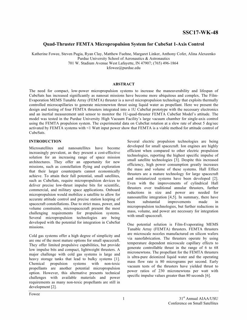
The FEMTA nozzles used for the 1U, single-axis rotation experiment are the fourth design iteration for the device. The throat is designed to be a maximum of 10 microns wide. This allows the firing temperature to be approximately 50° C. The desired throat depth is 50 microns and the inlet width is 40 microns. Figure 1 shows a schematic of FEMTA.
The heaters in the nozzle are platinum because platinum is not eroded by the ultra-pure water and has a sufficiently low electrical resistance.
Figure 1: Schematic of FEMTA Gen4 MEMS devices with nominal dimensions (not to scale)
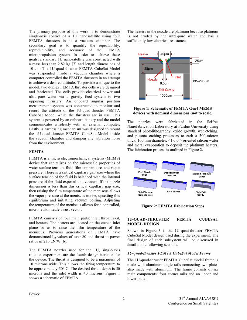
The nozzles were fabricated in the Scifres Nanofabrication Laboratory at Purdue University using standard photolithography, oxide growth, wet etching, and plasma etching processes to etch a 300-micron thick, 100 mm diameter, <1 0 0 > oriented silicon wafer and metal evaporation to deposit the platinum heaters. The fabrication process is outlined in Figure 2.
Figure 2: FEMTA Fabrication Steps
1U-QUAD-THRUSTER FEMTA CUBESAT MODEL DESIGN
Shown in Figure 3 is the 1U-quad-thruster FEMTA CubeSat Model design used during the experiment. The final design of each subsystem will be discussed in detail in the following sections.
1U-quad-thruster FEMTA CubeSat Model Frame
The 1U-quad-thruster FEMTA CubeSat model frame is made with aluminum angle rails connecting two plates also made with aluminum. The frame consists of six main components: four corner rails and an upper and lower plate.
Fowee 3 31st Annual AIAA/USU Conference on Small Satellites
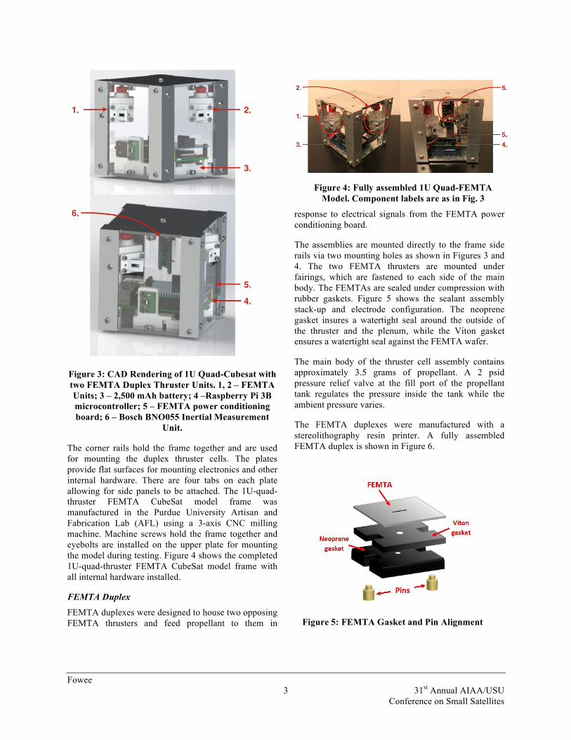
Figure 3: CAD Rendering of 1U Quad-Cubesat with two FEMTA Duplex Thruster Units. 1, 2 – FEMTA Units; 3 – 2,500 mAh battery; 4 –Raspberry Pi 3B microcontroller; 5 – FEMTA power conditioning board; 6 – Bosch BNO055 Inertial Measurement
Unit.
The corner rails hold the frame together and are used for mounting the duplex thruster cells. The plates provide flat surfaces for mounting electronics and other internal hardware. There are four tabs on each plate allowing for side panels to be attached. The 1U-quad-thruster FEMTA CubeSat model frame was manufactured in the Purdue University Artisan and Fabrication Lab (AFL) using a 3-axis CNC milling machine. Machine screws hold the frame together and eyebolts are installed on the upper plate for mounting the model during testing. Figure 4 shows the completed 1U-quad-thruster FEMTA CubeSat model frame with all internal hardware installed.
FEMTA Duplex
FEMTA duplexes were designed to house two opposing FEMTA thrusters and feed propellant to them in
response to electrical signals from the FEMTA power conditioning board.
The assemblies are mounted directly to the frame side rails via two mounting holes as shown in Figures 3 and 4. The two FEMTA thrusters are mounted under fairings, which are fastened to each side of the main body. The FEMTAs are sealed under compression with rubber gaskets. Figure 5 shows the sealant assembly stack-up and electrode configuration. The neoprene gasket insures a watertight seal around the outside of the thruster and the plenum, while the Viton gasket ensures a watertight seal against the FEMTA wafer.
The main body of the thruster cell assembly contains approximately 3.5 grams of propellant. A 2 psid pressure relief valve at the fill port of the propellant tank regulates the pressure inside the tank while the ambient pressure varies.
The FEMTA duplexes were manufactured with a stereolithography resin printer. A fully assembled FEMTA duplex is shown in Figure 6.
Figure 4: Fully assembled 1U Quad-FEMTA Model. Component labels are as in Fig. 3
Figure 5: FEMTA Gasket and Pin Alignment

Fowee 4 31st Annual AIAA/USU Conference on Small Satellites
Angular Position Sensor
An onboard system was implemented to measure the angular position of the CubeSat model during testing. To accurately assess and control the behavior of the model, this sensor should have a minimum angular precision of ±0.05°. Multiple concepts were considered to measure angular position, most of which involved optical and range finding sensors. However, sensors that employed lasers were not precise enough for the requirements of the experiment. A camera was also investigated as the primary measurement device. However, this concept was eliminated due to concerns about data acquisition speeds and CPU thermal limits in vacuum. An inertial measurement unit (IMU) sensor was ultimately chosen due to its enhanced accuracy and resolution as well as permitting real time data acquisition.
The Bosch BNO055 9-axis Absolute Orientation Sensor is the mounted IMU that monitors the dynamic behavior of the 1U-quad-thruster FEMTA CubeSat model with onboard calibration and sensor data fusion algorithms. These algorithms provide highly accurate orientation data with minimum steady state error and drift. The BNO055 contains an accelerometer, gyroscope, magnetometer, and temperature sensor. During the experiment, the readings from all sensors are recorded for future processing and noise filtration. The sensor communicates with the 1U-quad-thruster FEMTA CubeSat model controller via a native serial port connection rather than over an I2C bus. Despite this, it is still able to provide a high data acquisition rate of 10 kHz.
An external camera is used during the experiment to provide a visual reference as well. The camera is not
meant to provide accurate data but rather to create photo documentation of the model’s behavior inside the chamber.
Electronics
The motion of the 1U model must closely replicate that of a nanosatellite in a torque free environment. Therefore, a wireless communication system was designed to eliminate the physical influence of external wire harnessing. More specifically, a Raspberry Pi 3B was chosen as the onboard computer which communicates over an ad hoc wireless network to a second Raspberry Pi 3B mounted inside the vacuum chamber. This second Raspberry Pi then communicates via an Ethernet connection with an external Linux based computer. A simple network diagram of this is shown in Figure 7.
The Raspberry Pi has forty 3.3V digital outputs, however each FEMTA requires an analog signal from 0 to 5V. Therefore, a printed circuit board (PCB) was fabricated with a four channel, 16-bit digital-to-analog converter (DAC). The circuit board mounts directly to the 40-pin header on the Raspberry Pi. The DAC communicates with the Raspberry Pi via an I2C bus. Each of the four outputs from the DAC are connected to a current driver to reduce output impedance before the signal reaches the FEMTA. Each FEMTA in a single duplex is connected to the PCB through one 6-pin connector containing separate voltage pins and a shared ground pin. The remaining pins on each connector are configured to measure the propellant temperature within the FEMTA duplexes. This function may be added for future iterations of the thruster cell design. The circuit board contains a third 6-pin header that routes the IMU to a serial port and power supply on the Raspberry Pi. A basic diagram of the circuit board functionality is shown in Figure 8 and the circuit board is shown in Figure 9.
A preliminary thermal proofing test was performed to ensure that the Raspberry Pi and other electronics would be able to function in vacuum under the computational loads of the experiment without overheating.
Figure 6: FEMTA Duplex
Figure 7: Network Diagram

Fowee 5 31st Annual AIAA/USU Conference on Small Satellites
Figure 9: FEMTA Circuit Board
An assembly consisting of the lower plate, battery, Raspberry Pi, and PCB was placed in the small acrylic vacuum chamber at the High Vacuum Facility (HVF) at Purdue University as displayed in Figure 10. The test was completed at pressures between 0.075 and 0.113 torr. The results are listed in Table 1. The test confirmed that for a CPU workload duration of five minutes, the CPU temperature does not approach the Raspberry Pi operating limit of 70� .
Table 1: Average and Maximum CPU Temperatures
Control System
In order to effectively control the attitude of the 1U-quad-thruster FEMTA CubeSat model during testing, a proportional - integral - derivative (PID) controller was designed. The PID controller acts to minimize the difference between the actual model spin angle and the desired model spin angle.
Figure 10: Lower Plate Assembly in the Small Acrylic Vacuum Chamber
The reference signal that the PID controller tracks is modeled as a sinusoidal wave that approaches the target spin angle in a fixed rise time. The Equation for the reference signal is given by Equation 1:
𝜙 =!!!𝑠𝑖𝑛 !
!!𝑡 − !
!+ !!
!, 𝑡 < 𝑡!
𝜙! , 𝑟 ≥ 𝑡! (1)
In this model, ɸt is the target spin angle and tr is the rise time for the signal. The rise time is determined from the performance characteristics of the FEMTAs and the principle of conservation of angular momentum. The relationship for the rise time is shown in Equations 2 and 3 here:
𝑡! =!!!!!!!
(2)
𝑀! = 𝛼 !!
!𝐿 sin 45° (3)
Mx is the moment produced by each FEMTA, α is the thrust-to-power ratio, R is the electrical resistance of FEMTA, and L is the side length of the 1U-quad-thruster FEMTA CubeSat model. During operation, the controller outputs a value from negative one to positive one. The output value corresponds to the percentage of maximum thrust that will be applied. Negative thrust percentages are applied to the FEMTAs in the negative spin direction and positive thrust percentages are applied to the FEMTAs in the positive spin direction. Figure 11 shows an example of the 1U-quad-thruster FEMTA CubeSat model attempting to track a reference signal to a target of 150 degrees.
Load Duration (min)
Idle 0.167 (10 sec)
1.0 2.0 5.0
Average Temp (°C)
51.00 51.11 52.73 53.58 55.51
Maximum Temp (°C)
52.10 51.50 53.70 54.20 56.40
Figure 8: FEMTA Circuit Board Schematic

Fowee 6 31st Annual AIAA/USU Conference on Small Satellites
EXPERIMENT SETUP
Testing was conducted in the 4.2 m3 Chamber A at HVF which is evacuated by rotary/roots and diffusion pumps. Due to the sensitivity of FEMTA to particulates, the thrust cells were assembled in the clean environment of the Scifres Nanofabrication Laboratory at Purdue University Birck Nanotechnology Center. All components were soaked in an isopropyl bath and a water bath in a sonic cleaner.
The completed assembly was then transported to the HVF, where the thrust cells were filled with ultra-pure water in a clean glove box and examined for leaks. If the system was considered impermeable, the pressure relief valve was replaced and the mass of the thruster assemblies was measured. The resistance of each nozzle was then measured and each thruster was integrated
into the 1U CubeSat model.
The 1U Quad-FEMTA CubeSat model was then hung in the chamber using the harness system detailed in Figure 12. The spring in the harness dampened vibration from the roughing pump and blower. The monofilament fishing line and swivel connectors provide nearly free motion for the experiment. Tests were conducted at 30 - 40 microTorr.
As the system is still in preliminary data collection, no control scheme was used during the tests. Single thrusters were turned on and off by commands given to the Linux computer. Data was collected from a camera
Figure 12: Experiment harness system (top) and photograph of 1U Quad-FEMTA model installed in
HVF Chamber A.
Figure 11: Example Controller Response

Fowee 7 31st Annual AIAA/USU Conference on Small Satellites
at a viewing window into the chamber, which was lit with LED lights.
RESULTS
Data and Analysis
Table 2 gives the pre-test and post-test data for the thrust cells. The thrust cells were numbered, 1 and 2, and the nozzles were labeled A-D, with nozzle A and B on thruster 1 and nozzle C and D on thruster 2. Figure 13 shows the arrangement of the labels.
If FEMTA A or FEMTA C was activated, the CubeSat model rotated counterclockwise, and if FEMTA B or FEMTA D was activated, the CubeSat model rotated clockwise. Table 3 shows the data collected from the tests associated with the data in Table 2. During these tests, 3 of the 4 nozzles successfully rotated the model. FEMTA C appeared to have no effect on the rotation of the model. Thruster B and D had the most effect, with a maximum rotation rate of 4.0 and 4.9 degrees per second respectively.
Between tests 3 and 4 in Table 3, FEMTA B was used to counteract the settling rotation in the monofilament. This was done with marginal success, and while not providing numerical control data, it was demonstrated that FEMTA B could be reliably activated to decrease settling time.
The CubeSat was left to settle between each test. Figure 14 shows frames from the video recorded during the 7th
test. The time stamp in the images is recorded to the 30th of a second. The cube began to rotate at 45 seconds and made an entire rotation in 1 minute and 13 seconds. Each image corresponds to a quarter of a rotation. While pressure data was not recorded for this test, an
ion gauge that is visible from the camera location measures pressure inside the vacuum chamber.
Table 2: Thrust Cell Parameters
Thrust Cell 1 2
FEMTA Device Resistance and Rotation
Direction CW=Clockwise
CCW=Counter Clockwise
A: 73 Ω CCW
C: 71 Ω CCW
B: 72 Ω CW
D: 68 Ω CW
Dry Mass 33.0g 32.8g
Pre-Test Wet Mass 36.8g 36.8g
Post-Test Wet Mass 34.3g 34.7g
Total Water 3.8g 4.0g
Total Water Expended
2.5g 2.1g
Table 3: Test Result Summary
Test FEMTA Rotation Pressure Increase
Degrees per sec.
1 C NA No NA
2 A NA No NA
3 D clockwise Yes 3.2
4 B clockwise Yes 4.0
5 C NA No NA
6 A counter- clockwise Yes 1.63
7 D clockwise Yes 4.9
Figure 13: 1U-quad-thruster FEMTA CubeSat model Rotation and FEMTA Label Diagram

Fowee 8 31st Annual AIAA/USU Conference on Small Satellites
A pressure increase in the vacuum chamber will correspond to the introduction of water vapor to the system.
Another observation from these tests was that ice was ejected from the thrust cells sporadically throughout the test. This phenomenon is still being investigated.
The recorded mass of water expended in Table 3 does not correspond to a mass of water used during maneuvers. During pump down, a quantity of water is lost due to the change vapor pressure. The nozzles also produce low amounts of quiescent thrust, measured to be approximately 1 µN in previous tests, when not activated.
Figure 14: Frames from Test 7 Video (Thruster D, clockwise motion)
The data collected from these preliminary tests is qualitative in nature but does show that the system can provide single-axis rotation of a 1U CubeSat at power of < 1 Watt.
Future Work
This is an ongoing research effort. After this preliminary analysis, several changes to both the cube and control system will be made. New and more advanced sensors as well as a modified thrust cell design will be incorporated. Improvements will be made to both the data collection system and the control mechanisms to allow for more incremental tests.
Further advancements to FEMTA technology include adding shutters to prevent quiescent thrust, fabricating heaters that can be activated discretely, and increasing the temperature control of the heaters.
CONCLUSION
Small satellites are pushing the boundaries of spacecraft technology, requiring extreme size miniaturization and reduction in power consumption. Propulsion is uniquely affected as the limits of size and power consumption of traditional attitude control systems have not scaled proportionately to the satellite size. FEMTA merges the lucrative field of MEMS technology with small sat propulsion technology. This research sought to demonstrate controllable, single-axis rotation of a 1U quad-thruster FEMTA CubeSat model in a high vacuum environment using FEMTA. A CubeSat and thrust cells were fabricated for the experiment and a control schematic was developed. The CubeSat was controlled through a network of Raspberry Pis and a Linux computer.
This preliminary test of the system yielded no data from the control system, but did yield visual data from a digital recording of the test. A maximum slew rate of 4.9 degrees per sec was measured and single-axis rotation was successfully provided by the propulsion system at a power input of 250 mW.
Acknowledgments
The development of FEMTA Gen4 thrusters was supported by NASA SmallSat Partnership grant NNX15AW40A in collaboration with Goddard Space Flight Center. We also acknowledge Purdue University’s School of Aeronautics and Astronautics for providing the support for the undergraduate course. The undergraduate student team would like to thank Khary Parker and Carl Kotecki at GSFC for their help and advice on this project. The authors are grateful to the engineering staff at the Birck Nanotechnology Center and the Artisan Fabrication Laboratory at

Fowee 9 31st Annual AIAA/USU Conference on Small Satellites
Purdue University for their assistance. We also thank Professors Dan Dumbacher and David Spencer at Purdue for their criticism and feedback during the project design reviews.
References
1. Mueller, J., Hofer, R., Ziemer, J., “Survey of Propulsion Technologies Applicable to CubeSats,” NASA Jet Propulsion Laboratory, 2010.
2. NASA Ames Research Center, Mission Design Division, “Small Spacecraft Technology State of the Art,” NASA/TP-2015-216648/REV1, Moffett Field, CA, December 2015.
3. Hudson, J., Spangelo, S., Hine, A., Kolosa, D., & Lemmer, K., “Mission Analysis for CubeSats with Micropropulsion,” Journal of Spacecraft and Rockets. October 2016.
4. Pigeon, C. E., Orr, N. G., Larouche, B. P., Tarantini, V., Bonin, G., Zee, R. E., “A Low Power Cylindrical Hall Thruster for Next Generation Microsatellites,” Proceedings from 29th Conference on Small Satellites, 2015.
5. Smirnov, A., Raitses, Y., Fisch, N. J., “Plasma measurements in a 100 W cylindrical Hall thruster,” Journal of Applied Physics, Vol. 95, No. 5, 2004, pp. 2283-2292.
6. Cofer, A.G., O'Neill, W.J., Heister, S.D., Cardiff, E.H., and A.A. Alexeenko. “Film-evaporation microthruster for cubesats,” InMicro Electro Mechanical Systems (MEMS), 2016 IEEE 29th International Conference, Jan. 24th, 2016.
7. NanoRacks, LLC, “NanoRacks CubeSat Deployer (NRCSD) Interface Control Document,” NR-SRD-029, December 2013.


![Quad-Thruster FEMTA Micropropulsion System for CubeSat 1 ... · heavy storage tanks that lead to bulky systems [1]. Chemical propulsion systems with non-toxic ... The heaters in the](https://img.pdfslide.net/doc/110x75/602ea2c4703273791a0969d3/quad-thruster-femta-micropropulsion-system-for-cubesat-1-heavy-storage-tanks.jpg)