Embed Size (px)
Citation preview

3rd
International Conference on Automation, Control, Engineering and Computer Science (ACECS-2016)
20 - 22 March 2016 - Hammamet, Tunisia
Quadrature Phase Shift Keying and Offset Quadrature Phase Shift
Keying BER Performance Comparison
Amer Mohamed Daeri1, Mohamed Elfituri
2 and Amer Ragab Zerek
3
1 Zawia University. Faculty of Engineering , Computer Eng. Department
Zawia Libya
E-mail [email protected] 2 Biotecnology Research Center
Triploi - Libya
E-mail [email protected] / [email protected]
3 Zawia University. Faculty of Engineering , Electrical and Electronic Eng. Department
Zawia Libya
E-mail [email protected]
Abstract: Modulation plays an important role in
transmission of signals from transmitter to receiver in
all communication systems and the performance of
digital modulation systems is of the most important key
factors to achieve the best results of the communication
process . This paper presents a comparative study of
some performance parameters or performance metrics
of a digital communication system with the aid of a
Simulink model between Quadrature Phase Shift
Keying (QPSK) and Offset Quadrature Phase Shift
Keying (OQPSK) modulations in simple steps in terms
of description of inputs and outputs in simulations,
complex signal representations ,computations of bit
error rate (BER) simulated and theoretical results for
(QPSK ) , (OQPSK ) and Comparison of the symbol
error rate performance using MATLAB program .
KeyWords : QPSK ,OQPSK,, Modulator, performance
,Bit Error Rati , Simulator(Matlab),
I. Introduction In wireless, satellite, and space communication
systems, reducing error is critical. Wireless medium is
quite different from the counterpart using wires and
provides several advantages, for example; mobility,
better productivity, low cost, easy installation facility
and scalability. On the other hand, there are some
restrictions and disadvantages of various transmission
channels in wireless medium between receiver and
transmitter where transmitted signals arrive at receiver
with different power and time delay due to the
reflection, diffraction and scattering effects. Besides the
BER (Bit Error Rate) value of the wireless medium is
relatively high. These drawbacks sometimes introduce
destructive effects on the wireless data transmission
performance. As a result, error control is necessary in
these applications. During digital data transmission and
storage operations, performance criterion is commonly
determined by BER which is simply: Number of error
bits / Number of total bits. Noise in transmission
medium disturbs the signal and causes data corruptions.
Relation between signal and noise is described with
SNR (signal-to-noise ratio). Generally, SNR is defined
as signal power / noise power and is inversely
proportional with BER. It means, the less the BER the
higher is the SNR and the better is the communication
quality . A comparative study of QPSK and OQPSK
using Root Raised Cosine and Raised Cosine Pulse-
shaping Filters in terms of EVM, Magnitude Error,
Phase Error, Bandwidth efficiency and BER showed
that EVM is better for QOPSK with RRC filter
(α=0.35), OQPSK and QPSK with RRC (α=0.35) have
similar performance for magnitude and phase error,
OQPSK with RC filter (α=0.22) has better bandwidth
efficiency and in terms of BER QPSK with RRC filter
(α=0.7) showed better performance [1].
II. QPSK Modulation.
Quadrature Phase Shift Keying (QPSK) is a form of
Phase Shift Keying in which two bits are modulated at
once, selecting one of four possible carrier phase shifts
(0, 90, 180, or 270 degrees). QPSK allows the signal to
carry twice as much information as an ordinary PSK
using the same bandwidth. QPSK is used for satellite
transmission of MPEG2 video, cable modems,
Videoconferencing, cellular phone systems, and other
forms of digital communication over an RF carrier.

3rd
International Conference on Automation, Control, Engineering and Computer Science (ACECS-2016)
20 - 22 March 2016 - Hammamet, Tunisia
QPSK (Quadrature Phase Shift Keying) is one of the
modulation schemes used in wireless communication
system due to its ability to transmit twice the data rate
for a given bandwidth. The mathematical analysis
shows that QPSK can be used either to double the data
rate compared with a BPSK system while maintaining
the same bandwidth of the signal, or to maintain the
data-rate of BPSK but halving the bandwidth needed. In
this latter case, the BER of QPSK is exactly the same as
the BER of BPSK [2].The QPSK modulator is
illustrated in fig 1.The binary sequence is separated by
the serial-to-parallel converter into odd-bit-sequence for
I channel and even bit- sequence for Q channel.[3]
Fig. 1. QPSK modulator
ae(t) and ao(t) can be detect and estimated
independently the streams by means of two BPSK
demodulators in parallel. This is illustrated in the
coherent QPSK demodulator shown in Fig. 2. Note that
after the estimates of the bit streams ae(t) and ao(t) are
performed, a parallel-to-serial converter produces the
estimate of the transmitted data bit stream
Fig. 2 Coherent QPSK demodulator
III. Offset QPSK Modulation.
The idea behind the offset QPSK (OQPSK) or
staggered QPSK (SQPSK) modulation is very simple,
though very interesting. A QPSK signal can be formed
by adding two independent BPSK signals, one carrying
even data bits and the other carrying odd data bits.
Observing the waveforms shown in Fig. 3 ,it can be
noticed that whenever the in-phase or the Quadrature
component of the BPSK signal exhibits a phase
transition, the corresponding QPSK phase transition is
±π/2.[ 3]
Now consider the block diagram shown in Fig. 4, in
which the insertion of a delay in the even data stream is
the only difference between a conventional QPSK
modulator and the resulting OQPSK modulator.
Fig. 3 . In-phase, quadrature and composite phase transitions of
a QPSK signal
This delay guarantees that phase transitions in the in-
phase and quadrature component BPSK signals never
occur Simultaneously , avoiding the occurrence of
phase transitions of ±π in the resultant OQPSK signal.
As a consequence, a filtered OQPSK signal will exhibit
lower envelope fluctuations, becoming a more
attractive choice as compared to the conventional
QPSK modulation when nonlinear distortion is present
in the signal path.
Fig. 4 OQPSK modulator
Offset quadrature phase-shift keying OQPSK is a
variant of Phase Shift Keying modulation using 4
different values of the phase to transmit. It is sometimes
called Staggered quadrature phase shift keying SQPSK
. OQPSK limits the phase-jumps that occur at symbol
boundaries to no more than 90° and reduces the effects
on the amplitude of the signal due to any low-pass
filtering. [6]
The implementation shown in Fig. 5 still corresponds to
the multiplexing of two independent data streams
through orthogonal carriers, as in the case of the
3rd
International Conference on Automation, Control, Engineering and Computer Science (ACECS-2016)
20 - 22 March 2016 - Hammamet, Tunisia
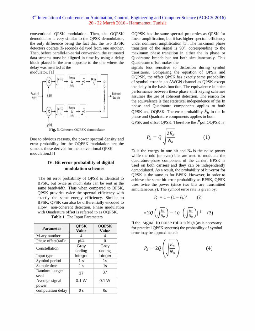
conventional QPSK modulation. Then, the OQPSK
demodulator is very similar to the QPSK demodulator,
the only difference being the fact that the two BPSK
detectors operate Tb seconds delayed from one another.
Then, before parallel-to-serial conversion, the estimated
data streams must be aligned in time by using a delay
block placed in the arm opposite to the one where the
delay was inserted at the
modulator. [1]
Fig. 5. Coherent OQPSK demodulator
Due to obvious reasons, the power spectral density and
error probability for the OQPSK modulation are the
same as those derived for the conventional QPSK
modulation.[5]
IV. Bit error probability of digital
modulation schemes
The bit error probability of QPSK is identical to
BPSK, but twice as much data can be sent in the
same bandwidth. Thus when compared to BPSK,
QPSK provides twice the spectral efficiency with
exactly the same energy efficiency. Similar to
BPSK, QPSK can also be differentially encoded to
allow non-coherent detection. Phase modulation
with Quadrature offset is referred to as OQPSK.
Table 1 The Input Parameters
OQPSK has the same spectral properties as QPSK for
linear amplification, but it has higher spectral efficiency
under nonlinear amplification [1]. The maximum phase
transition of the signal is 90°, corresponding to the
maximum phase transition in either the in phase or
Quadrature branch but not both simultaneously. This
Quadrature offset makes the
signals less sensitive to distortion during symbol
transitions. Comparing the equation of QPSK and
OQPSK, the offset QPSK has exactly same probability
of symbol error in an AWGN channel as QPSK except
the delay in the basis function. The equivalence in noise
performance between these phase shift keying schemes
assumes the use of coherent detection. The reason for
the equivalence is that statistical independence of the In
phase and Quadrature components applies to both
QPSK and OQPSK. The error probability in the In
phase and Quadrature components applies to both
QPSK and offset QPSK. Therefore the of OQPSK is
Eb is the energy in one bit and No is the noise power
while the odd (or even) bits are used to modulate the
quadrature-phase component of the carrier. BPSK is
used on both carriers and they can be independently
demodulated. As a result, the probability of bit-error for
QPSK is the same as for BPSK: However, in order to
achieve the same bit-error probability as BPSK, QPSK
uses twice the power (since two bits are transmitted
simultaneously). The symbol error rate is given by:
. =
(3)
If the signal to noise ratio is high (as is necessary
for practical QPSK systems) the probability of symbol
error may be approximated:
Parameter QPSK
Value
OQPSK
Value
M-ary number 4 4
Phase offset(rad): pi/4 0
Constellation Gray
coding
Gray coding
Input type Integer Integer
Symbol period 1 s 1s
Sample time 1 s 1s
Random integer
seed 37 37
Average signal
power 0.1 W 0.1 W
computation delay 0 s 0s
3rd
International Conference on Automation, Control, Engineering and Computer Science (ACECS-2016)
20 - 22 March 2016 - Hammamet, Tunisia
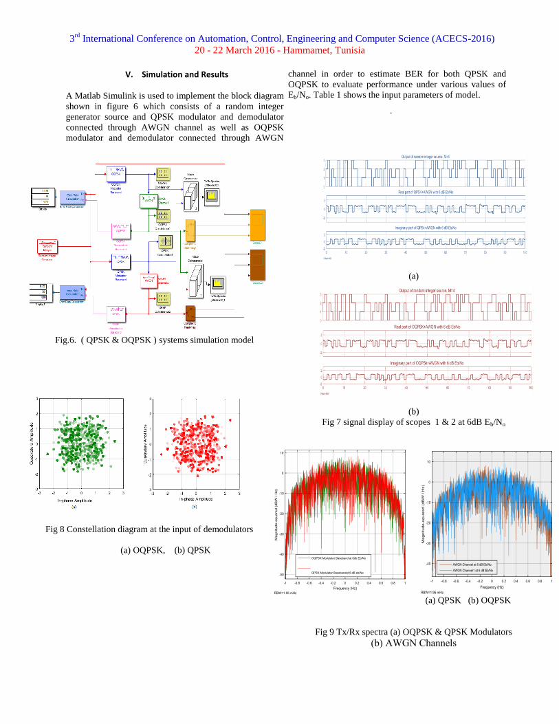
V. Simulation and Results
A Matlab Simulink is used to implement the block diagram
shown in figure 6 which consists of a random integer
generator source and QPSK modulator and demodulator
connected through AWGN channel as well as OQPSK
modulator and demodulator connected through AWGN
channel in order to estimate BER for both QPSK and
OQPSK to evaluate performance under various values of
Eb/No. Table 1 shows the input parameters of model.
.
Fig.6. ( QPSK & OQPSK ) systems simulation model
Fig 8 Constellation diagram at the input of demodulators
(a) OQPSK, (b) QPSK
(a)
(b)
Fig 7 signal display of scopes 1 & 2 at 6dB Eb/No
(a) QPSK (b) OQPSK
Fig 9 Tx/Rx spectra (a) OQPSK & QPSK Modulators
(b) AWGN Channels
3rd
International Conference on Automation, Control, Engineering and Computer Science (ACECS-2016)
20 - 22 March 2016 - Hammamet, Tunisia
The simulation was run several times by varying the
Eb/No value for both AWGN channels 1 & 2 using the
model in fig 6.The range for Eb/No at which the BER
values are calculated is -6 to 6 dB for both QPSK and
OQPSK, From simulation several results were obtained
which are illustrated in the show figures. Fig 7 shows
the display of scopes 1 & 2 for the real part and
imaginary part of the input digital signal at AWGN
Eb/No of 6 dB for both OQPSK and QPSK. Fig 8 show
the constellation diagram for both OQPSK and QPSK at
the input of the demodulators. Fig 9 shows the TX/Rx
spectra for the OQPSK and QPSK baseband modulators
and the AWGN channels 1 & 2.From the obtained
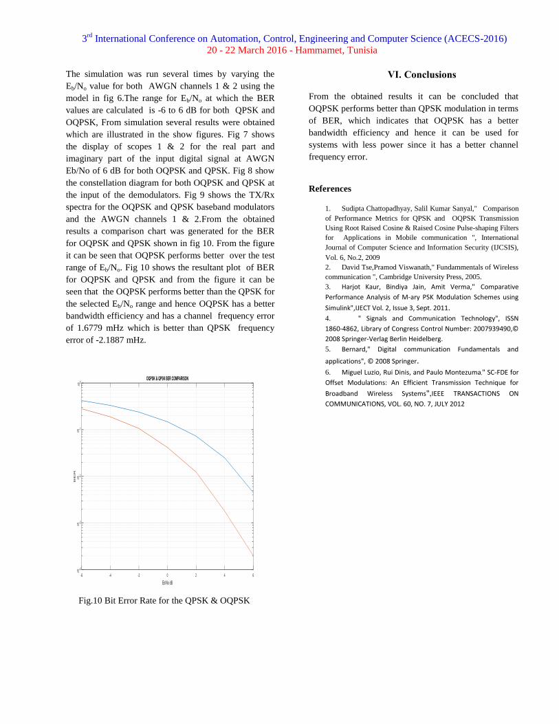
results a comparison chart was generated for the BER
for OQPSK and QPSK shown in fig 10. From the figure
it can be seen that OQPSK performs better over the test
range of Eb/No. Fig 10 shows the resultant plot of BER
for OQPSK and QPSK and from the figure it can be
seen that the OQPSK performs better than the QPSK for
the selected Eb/No range and hence OQPSK has a better
bandwidth efficiency and has a channel frequency error
of 1.6779 mHz which is better than QPSK frequency
error of -2.1887 mHz.
Fig.10 Bit Error Rate for the QPSK & OQPSK
VI. Conclusions
From the obtained results it can be concluded that
OQPSK performs better than QPSK modulation in terms
of BER, which indicates that OQPSK has a better
bandwidth efficiency and hence it can be used for
systems with less power since it has a better channel
frequency error.
References
1. Sudipta Chattopadhyay, Salil Kumar Sanyal," Comparison
of Performance Metrics for QPSK and OQPSK Transmission
Using Root Raised Cosine & Raised Cosine Pulse-shaping Filters
for Applications in Mobile communication ", International
Journal of Computer Science and Information Security (IJCSIS),
Vol. 6, No.2, 2009
2. David Tse,Pramod Viswanath," Fundammentals of Wireless
communication ", Cambridge University Press, 2005.
3. Harjot Kaur, Bindiya Jain, Amit Verma," Comparative
Performance Analysis of M-ary PSK Modulation Schemes using
Simulink",IJECT Vol. 2, Issue 3, Sept. 2011.
4. " Signals and Communication Technology", ISSN
1860-4862, Library of Congress Control Number: 2007939490,©
2008 Springer-Verlag Berlin Heidelberg. 5. Bernard," Digital communication Fundamentals and
applications", © 2008 Springer. 6. Miguel Luzio, Rui Dinis, and Paulo Montezuma," SC-FDE for
Offset Modulations: An Efficient Transmission Technique for
Broadband Wireless Systems",IEEE TRANSACTIONS ON
COMMUNICATIONS, VOL. 60, NO. 7, JULY 2012