Embed Size (px)
Citation preview
QUALIFICATION TEST REPORT
FOR
CARLISLE IT P/N: P317GD8-1CC (CGB4PS08VL00) and P186GD8-1CC
(CGC4RS08236)
DATE CODE: 1541, 1542
WO: 1260651, 1261323
SSMP MALE, 8 POSITION,
PCB VERTICAL MOUNT
CARLISLE INTERCONNECT TECHNOLOGIES 12900 ALONDRA BLVD, CERRITOS CA 90703-2108
TEL: +1(562) 498-0901 FAX:+1(562) 494-7611
REV. A
P317GD8-1CC-QTR REVISION: A
Page 2 of 38
TABLE OF CONTENTS 1.0 PURPOSE_____________________________________________________5 2.0 APPLICABLE DOCUMENTS________________________________________5 3.0 GENERAL TEST REQUIREMENTS___________________________________6 3.1 Definition of Requirements__________________________________6 3.2 Test Facilities_____________________________________________6 3.3 Equipments and Tools________________________________________6 4.0 TEST METHODS AND RESULTS____________________________________6 4.1 Subgroup I__________________________________________________6 4.2 Subgroup II_________________________________________________7 4.3 Subgroup III________________________________________________8 4.4 Subgroup IV________________________________________________10 4.5 Subgroup V_________________________________________________11 4.6 Subgroup VI________________________________________________12 5.0 CONCLUSIONS _______________________________________________12
FIGURES
FIGURE 1 Center Contact Retention Setup__________________________13 FIGURE 2 Corrosion Setup_________________________________________13 FIGURE 3 VSWR and RF Insertion Loss Setup________________________14 FIGURE 4 Durability, Force to Engage/ Disengage Setup____________14 FIGURE 5 Contact Resistance Setup________________________________15 FIGURE 6 Vibration Setup_________________________________________15 FIGURE 7 Shock (specified pulse) Setup___________________________17 FIGURE 8 Thermal Shock Setup_____________________________________18 FIGURE 9 DWV and Insulation Resistance Setup_____________________19 FIGURE 10 Moisture Resistance Setup______________________________19
ATTACHMENTS ATTACHMENT I Center Contact Retention and Corrosion ATTACHMENT II VSWR and Connector Durability ATTACHMENT III Contact Resistance, Vibration, Shock (specified
pulse), Thermal Shock, Moisture Resistance ATTACHMENT IV RF Insertion Loss ATTACHMENT V Contact Resistance ATTACHMENT VI Carlisle IT Equipment List
P317GD8-1CC-QTR REVISION: A
Page 3 of 38
REVISIONS
A
06/17/16
Added VSWR vs. Axial Offset Datasheet
D. Artin
REV DATE DESCRIPTION PREPARED BY
APPROVED BY (Design Engineer)
NC 12/16/15 INITIAL RELEASE D. Artin
P317GD8-1CC-QTR REVISION: A
Page 4 of 38
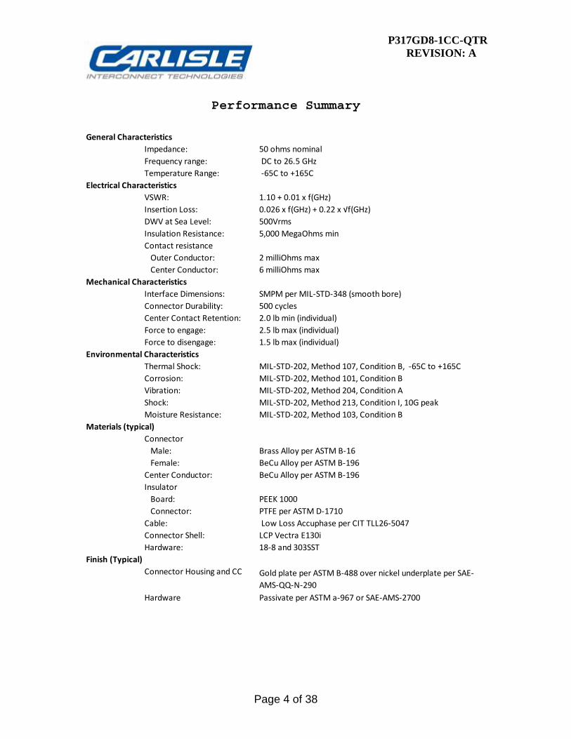
Performance Summary General Characteristics
Impedance: 50 ohms nominal
Frequency range: DC to 26.5 GHz
Temperature Range: ‐65C to +165C
Electrical Characteristics
VSWR: 1.10 + 0.01 x f(GHz)
Insertion Loss: 0.026 x f(GHz) + 0.22 x √f(GHz)
DWV at Sea Level: 500Vrms
Insulation Resistance: 5,000 MegaOhms min
Contact resistance
Outer Conductor: 2 milliOhms max
Center Conductor: 6 milliOhms max
Mechanical Characteristics
Interface Dimensions: SMPM per MIL‐STD‐348 (smooth bore)
Connector Durability: 500 cycles
Center Contact Retention: 2.0 lb min (individual)
Force to engage: 2.5 lb max (individual)
Force to disengage: 1.5 lb max (individual)
Environmental Characteristics
Thermal Shock: MIL‐STD‐202, Method 107, Condition B, ‐65C to +165C
Corrosion: MIL‐STD‐202, Method 101, Condition B
Vibration: MIL‐STD‐202, Method 204, Condition A
Shock: MIL‐STD‐202, Method 213, Condition I, 10G peak
Moisture Resistance: MIL‐STD‐202, Method 103, Condition B
Materials (typical)
Connector
Male: Brass Alloy per ASTM B‐16
Female: BeCu Alloy per ASTM B‐196
Center Conductor: BeCu Alloy per ASTM B‐196
Insulator
Board: PEEK 1000
Connector: PTFE per ASTM D‐1710
Cable: Low Loss Accuphase per CIT TLL26‐5047
Connector Shell: LCP Vectra E130i
Hardware: 18‐8 and 303SST
Finish (Typical)
Connector Housing and CC Gold plate per ASTM B‐488 over nickel underplate per SAE‐
AMS‐QQ‐N‐290
Hardware Passivate per ASTM a‐967 or SAE‐AMS‐2700
P317GD8-1CC-QTR REVISION: A
Page 5 of 38
1.0 PURPOSE
This document is the Group C Test Report CIT PN P317GD8-1CC. All qualification testing was performed in accordance with the applicable documents stated in Section 2.0. The UUT(s) lot successfully completed and passed Groups A and B inspection prior to Group C Inspection. Production drawings re-identified to CGB4PS08VL00 (P317GD8-1CC) and CGC4RS08236 (P186GD8-1CC)
2.0 APPLICABLE DOCUMENTS
MIL-PRF-39012 General Performance
Specification, Connectors, Coaxial, Radio Frequency
MIL-STD-202 Test Method Standard, Electronics and Electrical Component Parts
ANSI/NCSL Z540-1 Calibration Laboratories and
Measuring and Test Equipment- General Requirements P317GD8-1CC CIT Connector Drawing 510-0-18 CIT Cable Drawing P186GD8-1CC CIT Plug, 8 position, Drawing
P317GD8-1CC-QTR REVISION: A
Page 6 of 38
3.0 GENERAL TEST REQUIREMENTS
3.1 Definition of Requirements
Unless otherwise specified herein, all UUT(s) are performed in accordance to the requirements and methods specified by CIT P317GD8-1CC, P186GD8-1CC, MIL-STD-202, and MIL-PRF-39012. The quantity of UUT(s) for Group C inspection is in compliance with the qualification inspection guidelines set by forth MIL-PRF-39012.
3.2 Test Facilities
Before measurements and tests are being conducted, the environment conditions in the test facility meet the required parameters stated in MIL-STD-202.
3.3 Equipments and Tools
For tests performed at Carlisle IT, all mechanical and electrical inspection equipment is calibrated and maintained in accordance with ANSI/NCSL Z540-1. A list of equipment is included in Attachment V.
4.0 TEST METHODS AND RESULTS
The UUT(s) follow the testing methods outlined in Group C Inspection process in accordance with TABLE VII of MIL-PRF-39012. The sample lot is divided into six subgroups containing 1 UUT(s) each. Accordingly, the test data is recorded and a datasheet is generated at each inspection step. As applicable, the UUT(s) are tested using the mating part cable assembly, P/N P186GD8-1CC.
4.1 Subgroup I
Only the UUT(s) assigned to this subgroup I are subjected to the inspections specified herein. The test methods in subgroup I inspection included: Center Contact Retention and Corrosion (Salt Spray).
P317GD8-1CC-QTR REVISION: A
Page 7 of 38
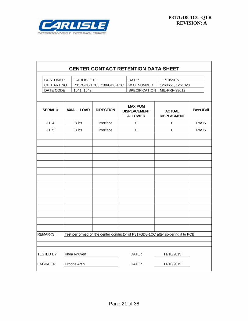
4.1.1 Requirements
Center Contact Retention – per MIL-PRF-39012, Para: 3.12 Corrosion - MIL-STD-202, Method 101, Condition B
4.1.2 Test Procedure
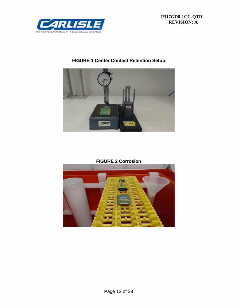
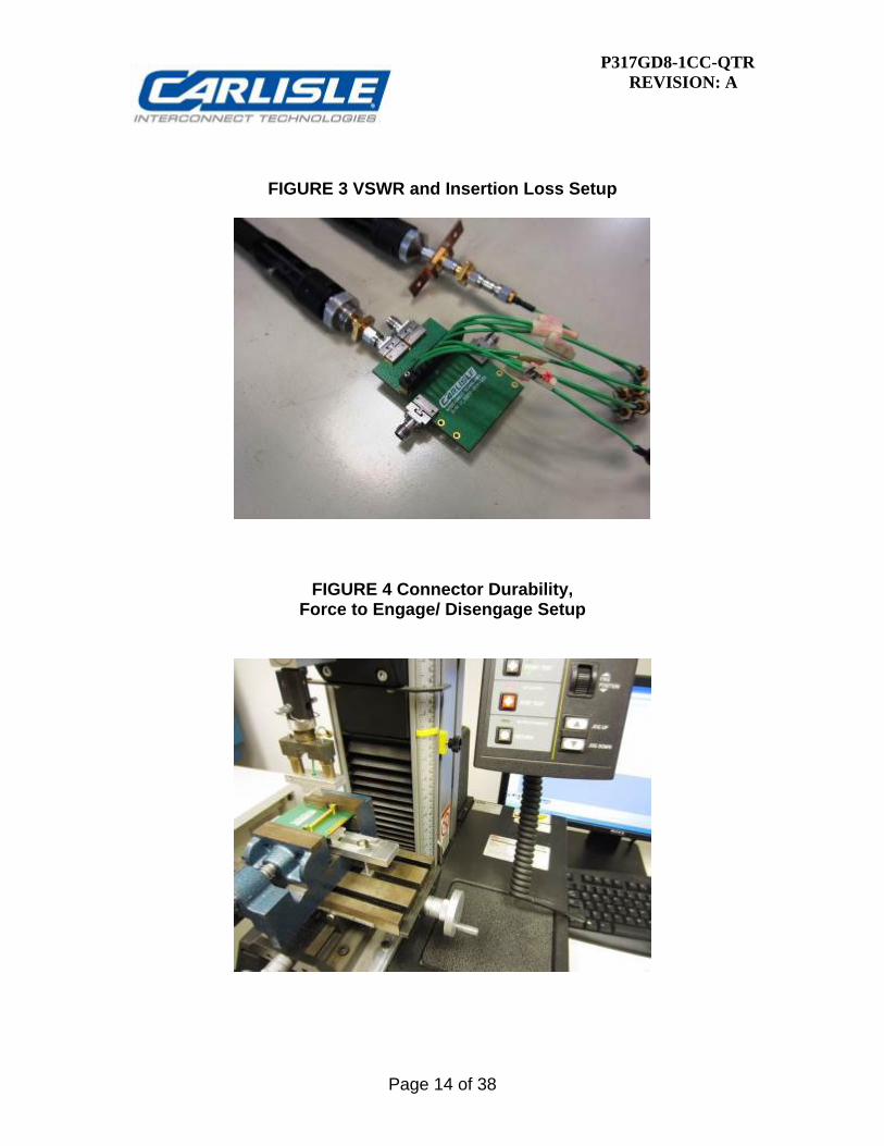
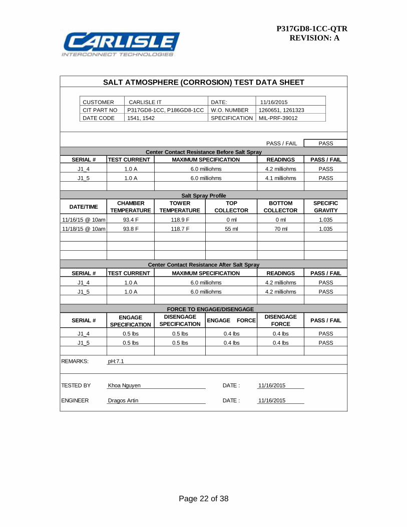
A total of 1 UUT(s) were tested for Subgroup I Inspection in accordance with MIL-PRF-39012. After soldering the connector to the PCB, the center contact position of P317GD8-1CC interface was measured. An axial force of 3.0 lbs was applied in the interface direction for 30 seconds. After the axial force was removed, the center contact was measured again and the displacement was recorded. Test setup is shown in Figure 1. Corrosion testing was performed per MIL-STD-202, Method 101, Condition B. The samples were exposed to 48hrs of salt spray, and they were inspected for signs of corrosion. Setup is shown in Figure 2.
4.1.3 Test Results
The UUT(s) completed the test sequence required by Subgroup I Inspection. Test datasheets are included in Attachment I.
4.2 Subgroup II Only the UUT(s) assigned to this subgroup II are subjected to the inspections specified herein. The test methods in Subgroup II Inspection included: VSWR and Connector Durability.
P317GD8-1CC-QTR REVISION: A
Page 8 of 38
4.2.1 Requirements
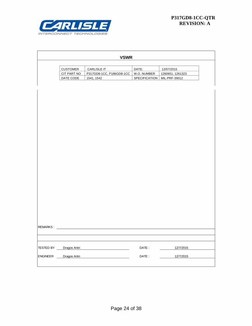
VSWR – per MIL-PRF-39012, Para: 3.14
Connector Durability – per MIL-PRF-39012, Para: 3.15
Force to Engage/ Disengage – MIL-PRF-39012, Para: 3.5
4.2.2 Test Procedure
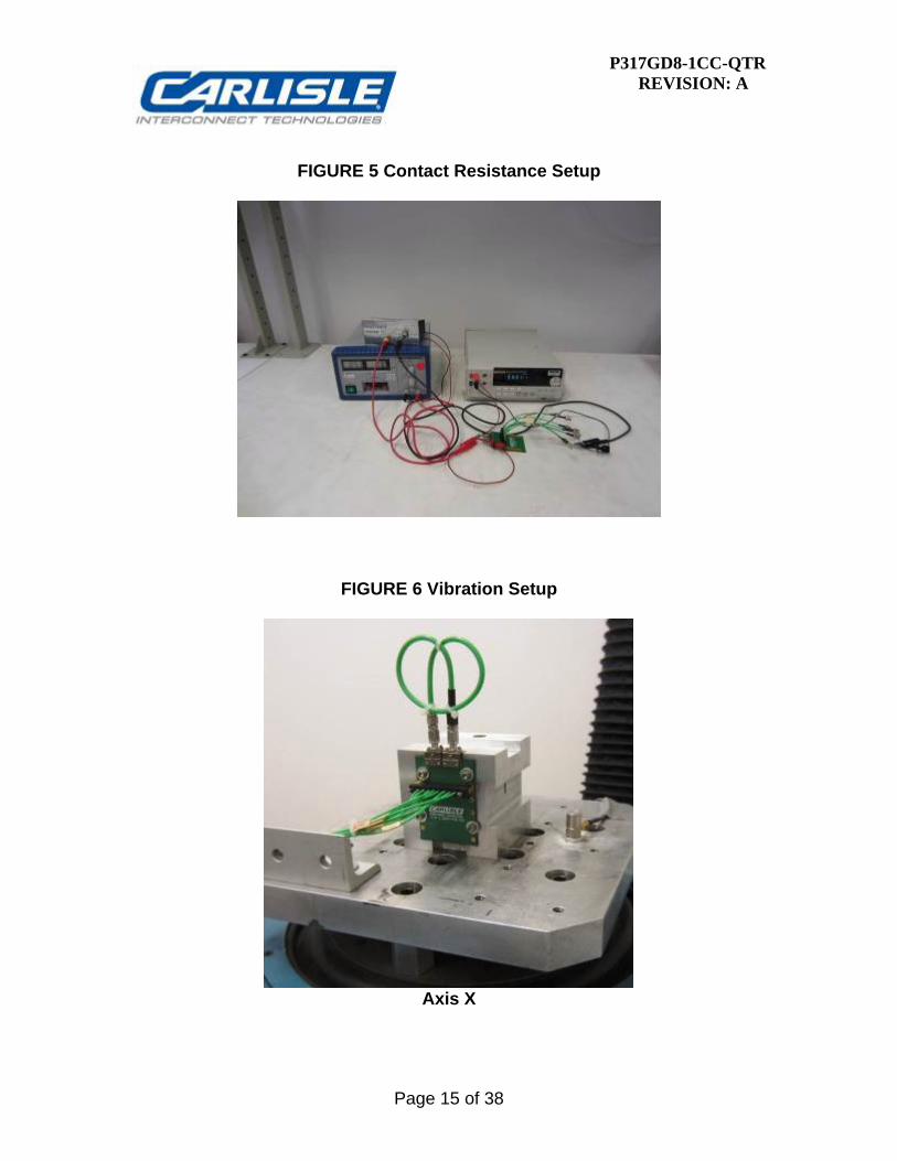
A total of 1 UTT(s) were tested for Subgroup II Inspection in accordance with per MIL-PRF-39012. The UUT(s) were soldered to PCB P/N V_SSMP-PCB-001 Rev B and the board was terminated with SWM female 1892-03A-5 connectors and P186G8-1CC connector assembly. VSWR measurements were taken using a PNA. A VSWR vs. axial demate offset test was also performed. Test setup is shown in Figure 3. One 510-0-18 (part of P186GD8-1CC) cable assembly was held in a fixture and mated /unmated to the P317GD8-1CC block for a total of 1000 cycles for Connector Durability. A visual examination was performed after 1000 cycles. Test setup is shown in Figure 3. Force to Engage/ Disengage was performed after Connector Durability test. Test setup is shown in Figure 4.
4.2.3 Test Results
The UUT(s) completed the test sequence required by Subgroup II Inspection. Test datasheets are included in Attachment II.
4.3 Subgroup III
Only the UUT(s) assigned to this subgroup III are subjected to the inspections specified herein. The test methods in Subgroup III Inspection included: Contact Resistance, Vibration, Shock (specified pulse), Thermal Shock, Moisture Resistance, Corona Level, and RF High Potential Withstanding Voltage.
P317GD8-1CC-QTR REVISION: A
Page 9 of 38
4.3.1 Requirements
Contact Resistance – per MIL-PRF-39012 3.16 Vibration – per MIL-PRF-39012 3.18, and MIL-STD-202, Method 204, Condition A Shock (specified pulse) – per MIL-PRF-39012 3.19 and MIL-STD-202, Method 213, Test Condition I, 10g peak
Thermal Shock – per MIL-PRF-39012 3.20 and MIL-STD-202, Method 107, Condition B, high temperature 165C
Moisture Resistance – per MIL-PRF-39012 3.21 and MIL-STD-202, Method 103, Condition B Dielectric Withstanding Voltage – per MIL-PRF-39012 3.17 Insulation Resistance – per MIL-PRF-39012 3.11
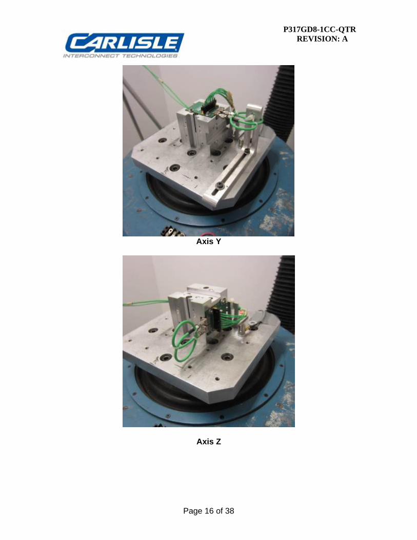
4.3.2 Test Procedure A total of 1 UUT(s) were tested for Subgroup III Inspection in accordance with MIL-PRF-39012. For Contact Resistance, each UUT(s) was connected across a circuit build in accordance with the instructions of MIL-PRF-39012, Para 4.6.13.1. The center contact resistance was calculated per MIL-PRF-39012, Para: 4.6.13.1. The center contact resistance of the 510-0-18 (part of P186GD8-1CC)cable was subtracted from the measurement. Test setup is shown in Figure 5. Vibration test was performed on 1 UUT(s) per MIL-STD-202, Method 204, Condition A. The UUT(s) were mounted on a test fixture, attached to the vibration table. The UUT(s) were subjected to vibration in the X, Y, and Z axis. Contact interruption was monitored during the vibration sweep. Test setup is shown in Figure 6.
P317GD8-1CC-QTR REVISION: A
Page 10 of 38
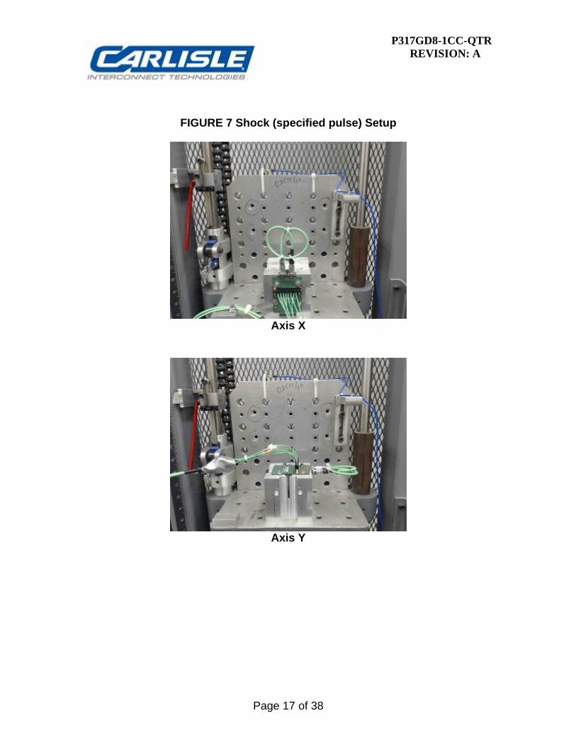
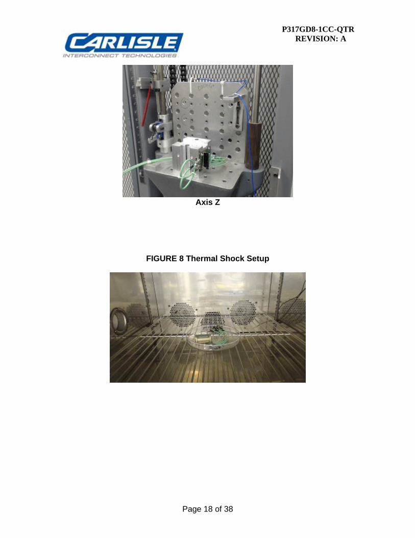
Shock – specified pulse- test was performed on 1 UUT(s) per MIL-STD-202, Method 213, Condition I, 10g peak. The UUT(s) were subjected to drop tests in the X, Y, and Z axis. Contact interruption was monitored during the free fall shock. Test setup is shown in Figure 7.
Thermal Shock was performed on 1 UTT(s) per MIL-STD-202, Method 107, Condition B, high temperature at 165C. A visual inspection was performed on the UUT(s) after temperature cycling. The center contact resistance and DWV were then re-measured. Test setups are shown in Figures 5, 8, and 9.
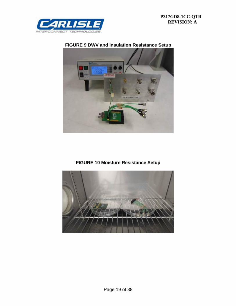
Moisture Resistance was performed on 1 UTT(s) per MIL-STD-202, Method 103, Condition B. Upon completion of the test DWV and Insulation Resistance tests were performed within a specified drying period after removal from the test chamber. Test setups are shown in Figures 9 and 10.
4.3.3 Test Results
The UUT(s) completed the test sequence required by Subgroup III Inspection. Test datasheets are included in Attachment III.
4.4 Subgroup IV Only the UUT(s) assigned to this Subgroup IV are subjected to the inspections specified herein. The test methods in Subgroup IV Inspection included: RF Leakage.
P317GD8-1CC-QTR REVISION: A
Page 11 of 38
4.4.1 Requirements RF Leakage – N/A
4.4.2 Test Procedure RF Leakage was not performed for the current samples of DUT.
4.4.3 Test Results
Not applicable.
4.5 Subgroup V Only the UUT(s) assigned to this Subgroup V are subjected to the inspections specified herein. The test methods in Subgroup V Inspection included: RF Insertion Loss.
4.5.1 Requirements RF Insertion Loss – per MIL-PRF-39012 3.27
4.5.2 Test Procedure The UUT(s) were soldered to PCB P/N V_SSMP-PCB-001 Rev B and the board was terminated with SWM female 1892-03A-5 connectors and P186G8 connector assembly. VSWR measurements were taken using a PNA. Test setup is shown in Figure 3.
4.5.3 Test Results
The UUT(s) completed the test sequence required by Subgroup V Inspection. Test datasheets are included in Attachment IV.
P317GD8-1CC-QTR REVISION: A
Page 12 of 38
4.6 Subgroup VI
Only the UUT(s) assigned to this subgroup VI are subjected to the inspections specified herein. The test methods in Subgroup VI Inspection included: Contact Resistance.
4.6.1 Requirements
Contact Resistance – per MIL-PRF-39012, Para: 3.16
A total of 1 UUT(s) were tested for Subgroup VI Inspection in accordance with MIL-PRF-39012. For Contact Resistance, each UUT(s) was connected across a circuit build in accordance with the instructions of MIL-PRF-39012, Para 4.6.13.1. The center contact resistance of the 510-0-18 (part of P186GD8-1CC)cable was subtracted from the measurement. Test setup is shown in Figure 5.
4.6.3 Test Results
The UUT(s) completed the test sequence required by Subgroup VI Inspection. Test datasheet is included in Attachment V.
5.0 CONCLUSION Based on the test results of Subgroups I, II, III, IV, V, and VI, the UUT(s), Carlisle IT P/N P317GD8-1CC completed Group C Inspection, as specified and recorded herein.
P317GD8-1CC-QTR REVISION: A
Page 13 of 38
FIGURE 1 Center Contact Retention Setup
FIGURE 2 Corrosion
P317GD8-1CC-QTR REVISION: A
Page 14 of 38
FIGURE 3 VSWR and Insertion Loss Setup
FIGURE 4 Connector Durability, Force to Engage/ Disengage Setup
P317GD8-1CC-QTR REVISION: A
Page 15 of 38
FIGURE 5 Contact Resistance Setup
FIGURE 6 Vibration Setup
Axis X
P317GD8-1CC-QTR REVISION: A
Page 16 of 38
Axis Y
Axis Z
P317GD8-1CC-QTR REVISION: A
Page 17 of 38
FIGURE 7 Shock (specified pulse) Setup
Axis X
Axis Y
P317GD8-1CC-QTR REVISION: A
Page 18 of 38
Axis Z
FIGURE 8 Thermal Shock Setup
P317GD8-1CC-QTR REVISION: A
Page 19 of 38
FIGURE 9 DWV and Insulation Resistance Setup
FIGURE 10 Moisture Resistance Setup
P317GD8-1CC-QTR REVISION: A
Page 20 of 38
ATTACHMENT I
Center Contact Retention, Corrosion
P317GD8-1CC-QTR REVISION: A
Page 21 of 38
J1_4 3 lbs interface 0 0 PASS
J1_5 3 lbs interface 0 0 PASS
REMARKS : Test performed on the center conductor of P317GD8-1CC after soldering it to PCB
TESTED BY Khoa Nguyen DATE : 11/10/2015
ENGINEER Dragos Artin DATE : 11/10/2015
CENTER CONTACT RETENTION DATA SHEET
SERIAL # AXIAL LOAD DIRECTIONMAXIMUM
DISPLACEMENT ALLOWED
ACTUAL DISPLACMENT
Pass /Fail
CUSTOMER CARLISLE IT DATE: 11/10/2015
CIT PART NO P317GD8-1CC, P186GD8-1CC W.O. NUMBER 1260651, 1261323
DATE CODE 1541, 1542 SPECIFICATION MIL-PRF-39012
P317GD8-1CC-QTR REVISION: A
Page 22 of 38
PASS / FAIL PASS
SERIAL # TEST CURRENT READINGS PASS / FAIL
J1_4 1.0 A 4.2 milliohms PASS
J1_5 1.0 A 4.1 milliohms PASS
11/16/15 @ 10am 93.4 F 118.9 F 0 ml 0 ml 1.035
11/18/15 @ 10am 93.8 F 118.7 F 55 ml 70 ml 1.035
SERIAL # TEST CURRENT READINGS PASS / FAIL
J1_4 1.0 A 4.2 milliohms PASS
J1_5 1.0 A 4.2 milliohms PASS
J1_4 0.5 lbs 0.5 lbs 0.4 lbs 0.4 lbs PASS
J1_5 0.5 lbs 0.5 lbs 0.4 lbs 0.4 lbs PASS
REMARKS: pH:7.1
TESTED BY Khoa Nguyen DATE : 11/16/2015
ENGINEER Dragos Artin DATE : 11/16/2015
DISENGAGE FORCE
BOTTOM COLLECTOR
SALT ATMOSPHERE (CORROSION) TEST DATA SHEET
FORCE TO ENGAGE/DISENGAGE
Center Contact Resistance Before Salt Spray
Salt Spray Profile
Center Contact Resistance After Salt Spray
DATE/TIME
6.0 milliohms
TOWER TEMPERATURE
SERIAL # ENGAGE SPECIFICATION
DISENGAGE SPECIFICATION
ENGAGE FORCE
CHAMBER TEMPERATURE
SPECIFIC GRAVITY
PASS / FAIL
MAXIMUM SPECIFICATION
MAXIMUM SPECIFICATION
6.0 milliohms
6.0 milliohms
6.0 milliohms
TOP COLLECTOR
CUSTOMER CARLISLE IT DATE: 11/16/2015
CIT PART NO P317GD8-1CC, P186GD8-1CC W.O. NUMBER 1260651, 1261323
DATE CODE 1541, 1542 SPECIFICATION MIL-PRF-39012
P317GD8-1CC-QTR REVISION: A
Page 23 of 38
ATTACHMENT II
VSWR and Connector Durability
P317GD8-1CC-QTR REVISION: A
Page 24 of 38
REMARKS :
TESTED BY Dragos Artin DATE : 12/7/2015
ENGINEER Dragos Artin DATE : 12/7/2015
VSWR
CUSTOMER CARLISLE IT DATE: 12/07/2015
CIT PART NO P317GD8-1CC, P186GD8-1CC W.O. NUMBER 1260651, 1261323
DATE CODE 1541, 1542 SPECIFICATION MIL-PRF-39012
P317GD8-1CC-QTR REVISION: A
Page 25 of 38
REMARKS :
TESTED BY Dragos Artin DATE : 6/7/2016
ENGINEER Dragos Artin DATE : 6/7/2016
VSWR VS AXIAL OFFSET
CUSTOMER CARLISLE IT DATE: 06/07/2016
CIT PART NO P317GD8-1CC, P186GD8-1CC W.O. NUMBER 1260651, 1261323
DATE CODE 1541, 1542 SPECIFICATION MIL-PRF-39012
P317GD8-1CC-QTR REVISION: A
Page 26 of 38
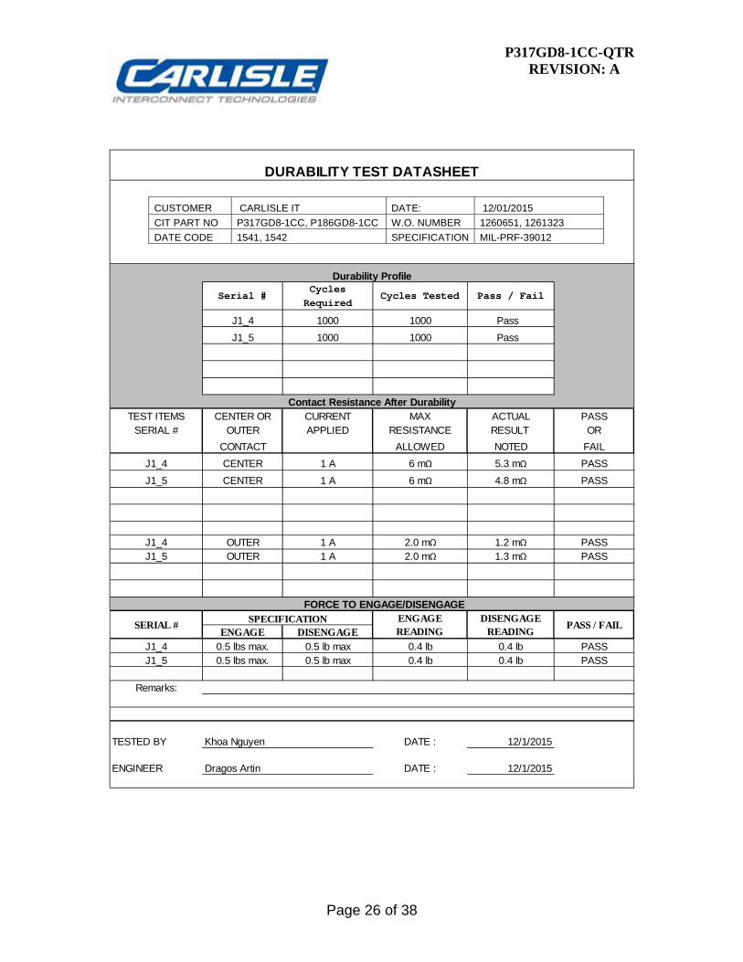
Serial #Cycles Required
Cycles Tested Pass / Fail
J1_4 1000 1000 Pass
J1_5 1000 1000 Pass
TEST ITEMS CENTER OR CURRENT MAX ACTUAL PASSSERIAL # OUTER APPLIED RESISTANCE RESULT OR
CONTACT ALLOWED NOTED FAIL
J1_4 CENTER 1 A 6 mΩ 5.3 mΩ PASS
J1_5 CENTER 1 A 6 mΩ 4.8 mΩ PASS
J1_4 OUTER 1 A 2.0 mΩ 1.2 mΩ PASSJ1_5 OUTER 1 A 2.0 mΩ 1.3 mΩ PASS
ENGAGE DISENGAGE
J1_4 0.5 lbs max. 0.5 lb max 0.4 lb 0.4 lb PASSJ1_5 0.5 lbs max. 0.5 lb max 0.4 lb 0.4 lb PASS
Remarks:
TESTED BY Khoa Nguyen DATE : 12/1/2015
ENGINEER Dragos Artin DATE : 12/1/2015
DURABILITY TEST DATASHEET
Durability Profile
FORCE TO ENGAGE/DISENGAGE
Contact Resistance After Durability
SPECIFICATION ENGAGE READING
DISENGAGE READING
SERIAL # PASS / FAIL
CUSTOMER CARLISLE IT DATE: 12/01/2015
CIT PART NO P317GD8-1CC, P186GD8-1CC W.O. NUMBER 1260651, 1261323
DATE CODE 1541, 1542 SPECIFICATION MIL-PRF-39012
P317GD8-1CC-QTR REVISION: A
Page 27 of 38
ATTACHMENT III
Contact Resistance, Vibration, Shock (specified pulse), Thermal Shock, Moisture Resistance
P317GD8-1CC-QTR REVISION: A
Page 28 of 38
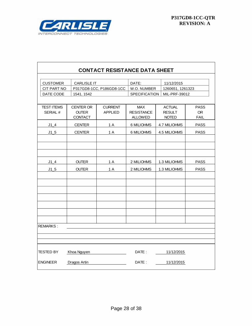
TEST ITEMS CENTER OR CURRENT MAX ACTUAL PASSSERIAL # OUTER APPLIED RESISTANCE RESULT OR
CONTACT ALLOWED NOTED FAIL
J1_4 CENTER 1 A 6 MILIOHMS 4.7 MILIOHMS PASS
J1_5 CENTER 1 A 6 MILIOHMS 4.5 MILIOHMS PASS
J1_4 OUTER 1 A 2 MILIOHMS 1.3 MILIOHMS PASS
J1_5 OUTER 1 A 2 MILIOHMS 1.3 MILIOHMS PASS
REMARKS :
TESTED BY Khoa Nguyen DATE : 11/12/2015
ENGINEER Dragos Artin DATE : 11/12/2015
CONTACT RESISTANCE DATA SHEET
CUSTOMER CARLISLE IT DATE: 11/12/2015
CIT PART NO P317GD8-1CC, P186GD8-1CC W.O. NUMBER 1260651, 1261323
DATE CODE 1541, 1542 SPECIFICATION MIL-PRF-39012
P317GD8-1CC-QTR REVISION: A
Page 29 of 38
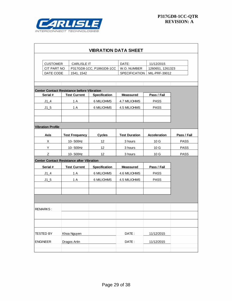
VIBRATION DATA SHEET
Serial # Test Current Specification Meassured Pass / Fail
J1_4 1 A 6 MILIOHMS 4.7 MILIOHMS PASS
J1_5 1 A 6 MILIOHMS 4.5 MILIOHMS PASS
Axis Test Frequency Cycles Test Duration Acceleration Pass / Fail
X 10- 500Hz 12 3 hours 10 G PASS
Y 10- 500Hz 12 3 hours 10 G PASS
Z 10- 500Hz 12 3 hours 10 G PASS
Serial # Test Current Specification Meassured Pass / Fail
J1_4 1 A 6 MILIOHMS 4.6 MILIOHMS PASS
J1_5 1 A 6 MILIOHMS 4.5 MILIOHMS PASS
REMARKS :
TESTED BY Khoa Nguyen DATE : 11/12/2015
ENGINEER Dragos Artin DATE : 11/12/2015
Vibration Profile
Center Contact Resistance after Vibration
Center Contact Resistance before Vibration
CUSTOMER CARLISLE IT DATE: 11/12/2015
CIT PART NO P317GD8-1CC, P186GD8-1CC W.O. NUMBER 1260651, 1261323
DATE CODE 1541, 1542 SPECIFICATION MIL-PRF-39012
P317GD8-1CC-QTR REVISION: A
Page 30 of 38
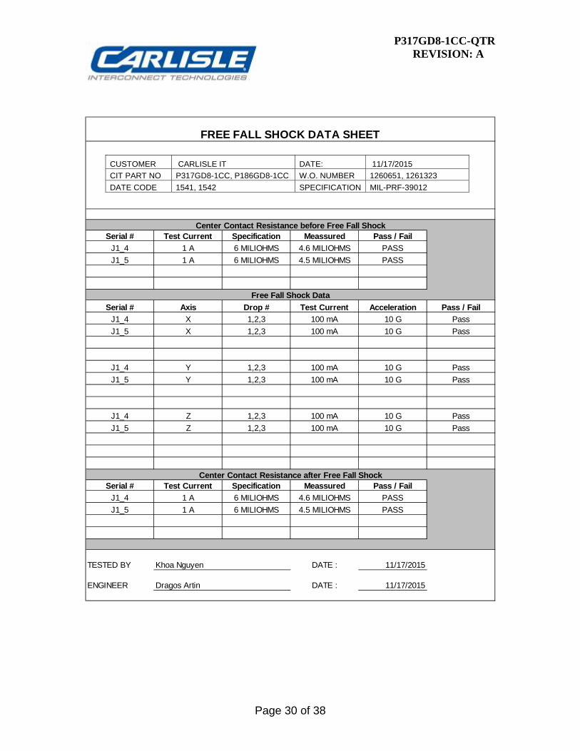
Serial # Test Current Specification Meassured Pass / Fail
J1_4 1 A 6 MILIOHMS 4.6 MILIOHMS PASS
J1_5 1 A 6 MILIOHMS 4.5 MILIOHMS PASS
Serial # Axis Drop # Test Current Acceleration Pass / Fail
J1_4 X 1,2,3 100 mA 10 G Pass
J1_5 X 1,2,3 100 mA 10 G Pass
J1_4 Y 1,2,3 100 mA 10 G Pass
J1_5 Y 1,2,3 100 mA 10 G Pass
J1_4 Z 1,2,3 100 mA 10 G Pass
J1_5 Z 1,2,3 100 mA 10 G Pass
Serial # Test Current Specification Meassured Pass / Fail
J1_4 1 A 6 MILIOHMS 4.6 MILIOHMS PASS
J1_5 1 A 6 MILIOHMS 4.5 MILIOHMS PASS
TESTED BY Khoa Nguyen DATE : 11/17/2015
ENGINEER Dragos Artin DATE : 11/17/2015
Free Fall Shock Data
Center Contact Resistance after Free Fall Shock
Center Contact Resistance before Free Fall Shock
FREE FALL SHOCK DATA SHEET
CUSTOMER CARLISLE IT DATE: 11/17/2015
CIT PART NO P317GD8-1CC, P186GD8-1CC W.O. NUMBER 1260651, 1261323
DATE CODE 1541, 1542 SPECIFICATION MIL-PRF-39012
P317GD8-1CC-QTR REVISION: A
Page 31 of 38
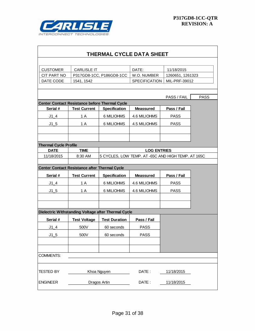
PASS / FAIL PASS
Serial # Test Current Specification Meassured Pass / Fail
J1_4 1 A 6 MILIOHMS 4.6 MILIOHMS PASS
J1_5 1 A 6 MILIOHMS 4.5 MILIOHMS PASS
DATE TIME LOG ENTRIES
11/18/2015 8:30 AM 5 CYCLES, LOW TEMP. AT -65C AND HIGH TEMP. AT 165C
Serial # Test Current Specification Meassured Pass / Fail
J1_4 1 A 6 MILIOHMS 4.6 MILIOHMS PASS
J1_5 1 A 6 MILIOHMS 4.6 MILIOHMS PASS
Serial # Test Voltage Test Duration Pass / Fail
J1_4 500V 60 seconds PASS
J1_5 500V 60 seconds PASS
COMMENTS:
TESTED BY DATE : 11/18/2015
ENGINEER DATE : 11/18/2015Dragos Artin
Thermal Cycle Profile
Center Contact Resistance before Thermal Cycle
THERMAL CYCLE DATA SHEET
Khoa Nguyen
Center Contact Resistance after Thermal Cycle
Dielectric Withstanding Voltage after Thermal Cycle
CUSTOMER CARLISLE IT DATE: 11/18/2015
CIT PART NO P317GD8-1CC, P186GD8-1CC W.O. NUMBER 1260651, 1261323
DATE CODE 1541, 1542 SPECIFICATION MIL-PRF-39012
P317GD8-1CC-QTR REVISION: A
Page 32 of 38
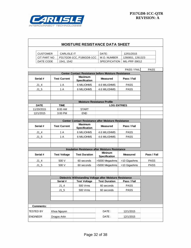
MOISTURE RESISTANCE DATA SHEET
PASS / FAIL PASS
Serial # Test CurrentMaximum
SpecificationMeasured Pass / Fail
J1_4 1 A 6 MILIOHMS 4.6 MILIOHMS PASS
J1_5 1 A 6 MILIOHMS 4.6 MILIOHMS PASS
DATE TIME LOG ENTRIES
11/20/2015 8:00 AM START
12/1/2015 3:00 PM END
Serial # Test CurrentMaximum
SpecificationMeasured Pass / Fail
J1_4 1 A 6 MILIOHMS 4.6 MILIOHMS PASS
J1_5 1 A 6 MILIOHMS 4.6 MILIOHMS PASS
Serial # Test Voltage Test DurationMininum
SpecificationMeasured Pass / Fail
J1_4 500 V 60 seconds >5000 Megaohms >10 Gigaohms PASS
J1_5 500 V 60 seconds >5000 Megaohms >10 Gigaohms PASS
Serial # Test Voltage Test Duration Pass / Fail
J1_4 500 Vrms 60 seconds PASS
J1_5 500 Vrms 60 seconds PASS
Comments:
TESTED BY Khoa Nguyen DATE : 12/1/2015
ENGINEER Dragos Artin DATE : 12/1/2015
Insulation Resistance after Moisture Resistance
Dielectric Withstanding Voltage after Moisture Resistance
Center Contact Resistance before Moisture Resistance
Moisture Resistance Profile
Center Contact Resistance after Moisture Resistance
CUSTOMER CARLISLE IT DATE: 12/01/2015
CIT PART NO P317GD8-1CC, P186GD8-1CC W.O. NUMBER 1260651, 1261323
DATE CODE 1541, 1542 SPECIFICATION MIL-PRF-39012
P317GD8-1CC-QTR REVISION: A
Page 33 of 38
ATTACHMENT IV
RF Insertion Loss
P317GD8-1CC-QTR REVISION: A
Page 34 of 38
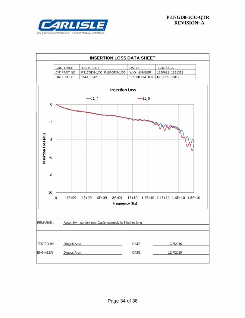
REMARKS : Assembly insertion loss; Cable assembly is 6 inches long
TESTED BY Dragos Artin DATE : 12/7/2015
ENGINEER Dragos Artin DATE : 12/7/2015
INSERTION LOSS DATA SHEET
CUSTOMER CARLISLE IT DATE: 12/07/2015
CIT PART NO P317GD8-1CC, P186GD8-1CC W.O. NUMBER 1260651, 1261323
DATE CODE 1541, 1542 SPECIFICATION MIL-PRF-39012
P317GD8-1CC-QTR REVISION: A
Page 35 of 38
ATTACHMENT V
Contact Resistance
P317GD8-1CC-QTR REVISION: A
Page 36 of 38
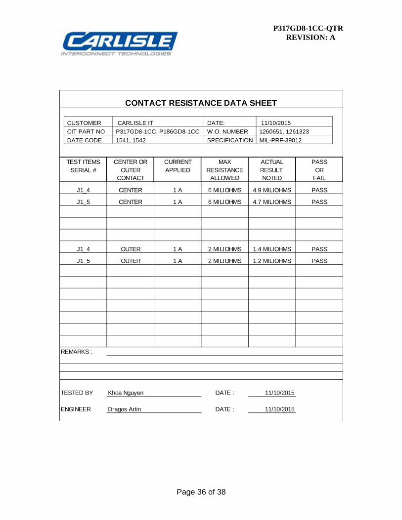
TEST ITEMS CENTER OR CURRENT MAX ACTUAL PASSSERIAL # OUTER APPLIED RESISTANCE RESULT OR
CONTACT ALLOWED NOTED FAIL
J1_4 CENTER 1 A 6 MILIOHMS 4.9 MILIOHMS PASS
J1_5 CENTER 1 A 6 MILIOHMS 4.7 MILIOHMS PASS
J1_4 OUTER 1 A 2 MILIOHMS 1.4 MILIOHMS PASS
J1_5 OUTER 1 A 2 MILIOHMS 1.2 MILIOHMS PASS
REMARKS :
TESTED BY Khoa Nguyen DATE : 11/10/2015
ENGINEER Dragos Artin DATE : 11/10/2015
CONTACT RESISTANCE DATA SHEET
CUSTOMER CARLISLE IT DATE: 11/10/2015
CIT PART NO P317GD8-1CC, P186GD8-1CC W.O. NUMBER 1260651, 1261323
DATE CODE 1541, 1542 SPECIFICATION MIL-PRF-39012
P317GD8-1CC-QTR REVISION: A
Page 37 of 38
ATTACHMENT VI
CARLISLE IT Equipment List
P317GD8-1CC-QTR REVISION: A
Page 38 of 38
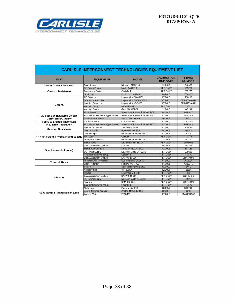
Center Contact Retention Drop Gauge Mitutoyo 2416F-10 11/2016 240688DC Power Supply Model 14600PS REF.ONLY 219221Resistance Tester Carlisle IT REF.ONLY T-7277Multimeter BK Precision-2703B 08/2016 20749060PD Detector Hypotronics DDX-9101 07/2016 170116Separation Capacitor Hypotronics PSF25/1/DDX 07/2016 BFR-1598-A314Injection Capacitor Hypotronics CIC-100 07/2016 BFR-2253-A314Vacuum Pump AVAC-DV-4E REF.ONLY 908Vacuum Gauge Gast Mfg./169-08 11/2016 AE136Hipot Tester Associated Research Model 3705 08/2016 9621647
Dielectric Withstanding Voltage Associated Research Hypot Tester Associated Research Model 3770 07/2016 9630303
Connector Durability Instron Force Gauge Instron 5542P8109 06/2016 41721
Force to Engage/ Disengage Torque Wrench CDI 151LD1N 07/2016 1109312661
Insulation Resistance Associated Research Hypot Tester Associated Research Model 3770 07/2016 9630303Humidity Chamber TestEquity 123H 02/2016 230248Chart Recorder Honeywell-DR 4300 04/2016 31634-1Oscilloscope BK Precision Model 2530 07/2016 70126RF Tester Carlisle REF.ONLY T-7278Function Generator BK Precision Model 4017A 12/2016 401710Shock Tower Lab Equipment SD-10 REF.ONLY 2005-005Data Acquisition Module NI 9233 08/2016 391325Shear Accelerometer Model 353B11/482A22 02/2016 147281DC Power Supply Mastech-Model 14600PS REF.ONLY 219222Contact Monitoring setup Carlisle IT REF.ONLY T-7275Data Acquisition Module DATAQ -DI-710 REF.ONLY 0606-10947Thermal Shock Chamber Sun Systems EC13HA 04/2016 AA1904Chart Recorder Partlow MCR7000 04/2016 AA1904-1Controller Spectral Dynamics 2400 01/2016 2056Accelerometer VIP 2015A 02/2016 11166Exciter Qualmark MB C10 REF.ONLY 119Data Acquisition Module DATAQ -DI-710 REF.ONLY 100641-C-CDC Power Supply Mastech-Model 14600PS REF.ONLY 219222Amplifier DMA-3/3-C10 REF.ONLY 0606-10947Contact Monitoring setup Carlisle IT REF.ONLY T-7275Multimeter Fluke Model 179 08/2016 97600094Vector Network Analyzer Anritsu Model 37369A 02/2016 2206Agilent PNA E83648B 07/2016 MY43040300
VSWR and RF Transmission Loss
Vibration
Thermal Shock
Shock (specified pulse)
RF High Potential Withstanding Voltage
Moisture Resistance
Corona
Contact Resistance
CARLISLE INTERCONNECT TECHNOLOGIES EQUIPMENT LIST
MODELCALIBRATION
DUE DATESERIAL
NUMBERTEST EQUIPMENT