Embed Size (px)
Citation preview
N A S A S P A C E V E H I C L E DESIGN C R I T E R I A (STRUCTURES)
QUALIFICATION TESTING
MAY 1970
NATIONAL AERONAUTICS AND SPACE ADMINISTRATION
https://ntrs.nasa.gov/search.jsp?R=19710019569 2018-06-23T09:27:41+00:00Z
GUIDE TO THE USE OF THIS MONOGRAPH
The purpose of this monograph is to provide a uniform basis for design of flightworthy structure. I t summarizes for use in space vehicle development the significant experience and knowledge accumulated in research, development, and operational programs to date. It can be used to improve consistency in design, efficiency of the design effort, and confidence in the structure. All monographs in this series employ the same basic format - three major sections preceded by a brief INTRODUCTION, Section 1, and complemented by a set of REFERENCES.
The STATE OF THE ART, Section 2, reviews and assesses current design practices and identifies important aspects of the present state of technology. Selected references are cited to supply supporting information. This section serves as a survey of the subject that provides background material and prepares a proper technological base for the DESIGN CRITERIA and RECOMMENDED PRACTICES.
The DESIGN CRITERIA, Section 3, state what rules, guides, or limitations must be imposed to ensure flightworthiness. The criteria can serve as a checklist for guiding a design or assessing its adequacy.
The RECOMMENDED PRACTICES, Section 4, state how t o satisfy the criteria. Whenever possible, the best procedure is described; when this cannot be done, appropriate references are suggested. These practices, in conjunction with the criteria, provide guidance to the formulation of requirements for vehicle design and evaluation.
FOREWORD
NASA experience has indicated a need for uniform criteria for the design'of space vehicles. Accordingly, criteria are being developed in the following areas of technology:
Environment Structures Guidance and Control Chemical Propulsion
Individual components of this work will be issued as separate monographs as soon as they are completed. A list of all published monographs in this series can be found at the end of this document.
These monographs are to be regarded as guides t o the formulation of design requirements and specifications by NASA Centers and project offices.
This monograph was prepared under the cognizance of the Langley Research Center. The Task Manager was W. C. Thornton. The authors were M. D. Brinson and J. J . King of Ling-Temco-Vought Corporation. Other individuals assisted in developing the material and reviewing the drafts. In particular, the significant contributions made by H. P. Adam, T. P. Brooks, and I. Tuchman of McDonnell Douglas Corporation; E. F. Baird and R. Hilderman of Grumman Aircraft Engineering Corporation; T. N. Bartron of NASA Langley Research Center; E. G. Davies of Lockheed Missiles & Space Company; M. Dublin of General Dynamics Corporation; J . S . Gilbert of Chrysler Corporation; 0. L. Gillette of Hughes Aircraft Company; F. P. Klein of Electronic Specialty Company; H. W. Klopfenstein and H. J. Runstad of The Boeing Company; C. E. Lifer of NASA George C. Marshall Space Flight Center; D. R. Reese of Wyle Laboratories; and L. St. Leger of NASA Manned Spacecraft Center are hereby acknowledged.
NASA plans to update this monograph when need is established. Comments and, recommended changes in the technical content are invited and should be forwarded to the attention of the Design Criteria Office, Langley Research Center, Hampton,Virginia 23365.
May 1970
CONTENTS
1 . INTRODUCTION . . . . . . . . . . . . . . . . . . . . . . . . 6 . 1
2 . STATE OF THE ART . . . . . . . . . . . . . . . . . . . . . . . 4
2.1 Testconditions . . . . . . . . . . . . . . . . . . . . . . . 4 2.1.1 Load and Environmental Simulation . . . . . . . . . 5 2.1.2 Static Loads . . . . . . . . . . . . . . . . . . . . . 6 2.1.3 Vibration and Shock . . . . . . . . . . . . . . . . . 6 2.1.4 Thermal Environments . . . . . . . . . . . . . . . . 7 2.1.5 Vacuum Environments . . . . . . . . . . . . . . . . 7 2.1.6 Acoustic Environments . . . . . . . . . . . . . . . 7 2.1.7 Corrosive Environments . . . . . . . . . . . . . . . 8
2.2 Test Articles . . . . . . . . . . . . . . . . . . . . . . . . . 8
2.4 Test Instrumentation . . . . . . . . . . . . . . . . . . . . . 8 2.3 Support Structure . . . . . . . . . . . . . . . . . . . . . . 8
3 . CRITERIA . . . . . . . . . . . . . . . . . . . . . . . . . . . . 9
3.1 3.2 3.3 3.4 3.5 3.6 3.7
TestPlan . . . . . . . . . . . . . . . . . . . . . . . . . . . 9 Test Conditions . . . . . . . . . . . . . . . . . . . . . . 9 Test Articles . . . . . . . . . . . . . . . . . . . . . . . . . 9 Test Fixtures and Support Structure . . . . . . . . . . . . . 10 Instrumentation . . . . . . . . . . . . . . . . . . . . . . . 10 Accept-Reject Criteria . . . . . . . . . . . . . . . . . . . . 10 Test Documentation . . . . . . . . . . . . . . . . . . . . . 10 3.7.1 Test Procedure . . . . . . . . . . . . . . . . . . . . 10 3.7.2 Test Report . . . . . . . . . . . . . . . . . . . . . 10
*
4 . RECOMMENDED PRACTICES . . . . . . . . . . . . . . . . . . 10
4.1 Test Plan . . . . . . . . . . . . . . . . . . . . . . . . . . . 11 4.2 Test Conditions . . . . . . . . . . . . . . . . . . . . . . . 11
iii
4.2.1 Sequence and Combination of Environments . . . . 12 4.2.2 Levels . . . . . . . . . . . . . . . . . . . . . . . . 13 4.2.3 Duration . . . . . . . . . . . . . . . . . . . . . . . 14
4.3 Test Articles . . . . . . . . . . . . . . . . . . . . . . . . . 15 4.4 Quantity of Test Articles . . . . . . . . . . . . . . . . . . . 16 4.5 Test Fixtures and Support Structure . . . . . . . . . . . . . 16 4.6 Instrumentation . . . . . . . . . . . . . . . . . . . . . . . 17 4.3 Accept-Reject Criteria . . . . . . . . . . . . . . . . . . . . 18 418 Test Documentation . . . . . . . . . . . . . . . . . . . . . 18
4.8.1 Test Procedure . . . . . . . . . . . . . . . . . . . . 19 4.8.2 Test Report . . . . . . . . . . . . . . . . . . . . . 19
REFERENCES . . . . . . . . . . . . . . . . . . . . . . . . . . 21
NASA SPACE VEHICLE DESIGN CRITERIA MONOGRAPHS ISSUED TO DATE . . . . . . . . . . . . . . . 23
iv
QUALIFICATION TESTING
Conceptual design
Preliminary design
1. INTRODUCTION
Time
1
I 1
Qualification tests are conducted on flight-quality components, subsystems, and systems to demonstrate that structural design requirements have been achieved. In these tests, critical portions of the design loadings are simulated and the performance of the hardware is then compared with previously established accept-reject criteria based on mission requirements. The test loadings and durations are designed to give a high level of confidence that, if test specimens perform acceptably, similar items manufactured under similar conditions can survive the expected service environments. These loads and durations usually exceed expected flight loads and durations.
Final design and production
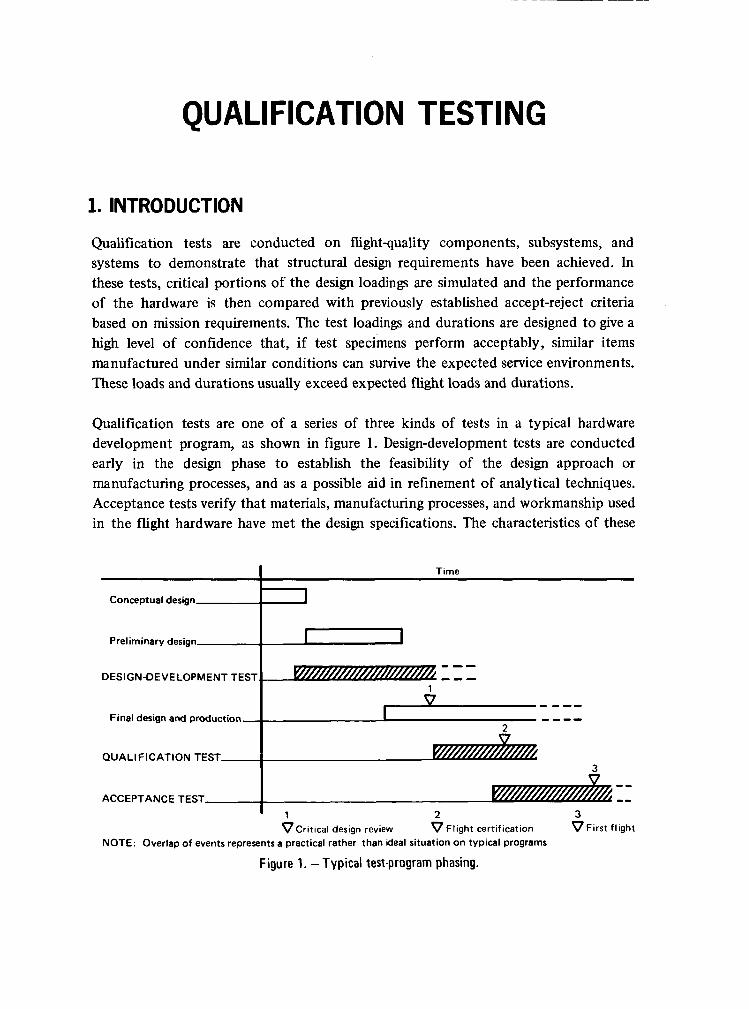
Qualification tests are one of a series of three kinds of tests in a typical hardware development program, as shown in figure 1. Design-development tests are conducted early in the design phase to establish the feasibility of the design approach or manufacturing processes, and as a possible aid in refinement of analytical techniques. Acceptance tests verify that materials, manufacturing processes, and workmanship used in the flight hardware have met the design specifications. The characteristics of these
1 V
I - --- ----
2 w
ACCEPTANCE TEST
DESIGN-DEVELOPMENT TEST I:::
-- -- QUALIFICATION TEST
n
' 1 2 3 VCritical design review v Flight certification VF i rs t flight
NOTE: Overlap of events represents a practical rather than ideal situation on typical programs
Figure 1. - Typical test-program phasing.
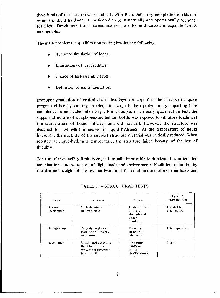
three kinds of tests are shown in table I. With the satisfactory completion of this test series, the flight hardware is considered to be structurally and operationally adequate for flight. Development and acceptance tests are to be discussed in separate NASA monographs.
Qualification To design ultimate load (not necessarily to failure).
Accqtancc Usually no! exceeding llight-limit loads
p r o o f test\). (except f o r prcssurc-
The main problems in qualification testing involve the following:
T o verify structural adequacy.
To ensure hardw a rc Inecls specifica t ions.
0 Accurate simulation of loads.
0 Limitations of test facilities.
0 Definition of instrumentation.
Improper simulation of critical design loadings can jeopardize the success of a space program either by causing an adequate design to be rejected or by imparting false confidence in an inadequate design. For example, in an early qualification test, the support structure of a high-pressure helium bottle was exposed to vibratory loading at the temperature of liquid nitrogen and did not fail. However, the structure was designed for use while immersed in liquid hydrogen. At the temperature of liquid hydrogen, the ductility of the support structure material was critically reduced. When retested a t liquid-hydrogen temperature, the structure failed because of the loss of ductility.
Because of test-facility limitations, it is usually impossible to duplicate the anticipated combinations and sequences of flight loads and environments. Facilities are limited by the size and weight of the test hardware and the combinations of extreme loads and
TABLE I. - STRUCTURAL TESTS
I I I Purpose Tests Load levels
Design- Variable, often development to destruction.
To determine ul t inia te strength and design feasibility.
Type of hardware used
Decided by engineering.
Flight quality.
~~~
I’light.
2

environments. The test plan separates the application of the loads and environments as dictated by these limitations. For example, one facility might be adequate for application of static loads and temperature, but another facility might be required for application of vibrations and acoustic noise. When the tests are separated in this way, the test plan must be carefully reviewed t o ensure that the hardware is not tested under unrealistic conditions, as in the repeated application of loads in sequential vibration and static tests.
Testing at the component level may not fully qualify the component and its related structure interfaces. In payload-separation qualification tests of a small launch vehicle, for example, a catch bracket designed to stop the motion of a separation clamp proved inadequate to prevent clamp-impact damage to the payload, even though the bracket was qualified at the component level.
This monograph presents criteria for structural qualification tests and recommends practices for selection of test specimens, design and selection of test fixtures and support structure, selection of critical test loadings and their level and duration, definition of instrumentation and data-acquisition requirements, and selection and application of accept-reject criteria for the interpretation of test results.
The design loadings applied in qualification tests of space vehicles include ground-handling loads, aerodynamic loads (static and transient), internal pressures, acceleration loads, shock loads, and loads resulting from vibration and from acoustic, thermal, and vacuum environments. The space-vehicle structure and its thermal-control system or protective coatings are tested to show that they are capable of performing for prolonged periods in the rigorous space environment of hard vacuum, radiation, particle impact, and temperature extremes. Mechanisms and lubricants are sometimes qualified for proper functioning in a simulated weightless state in a hard vacuum.
The selection of the critical test components, their level of assembly, the test conditions, the sequence of testing, the control and response instrumentation, and the accept-reject criteria are determined from prior analyses and tests. These data are based upon knowledge of the design strength and stiffness of the space-vehicle structure, as well as upon the knowledge of flight loads and environments.
O t h e r testing monographs relating to this document include those on design-development and acceptance testing. Design, analysis, and test considerations that bear on qualification testing are treated in the monograph on fracture control of metallic pressure vessels. Structural-discontinuity analysis and recommended tests are p re sen ted in t h e monograph on pressure-vessel discontinuities. The structural-vibration-prediction monograph treats tests performed to determine the vibratory response on equipment, spacecraft, and the major launch-vehicle structure.
5
2. STATE OF THE ART
Structural qualification tests have been conducted on space vehicles ranging in size from small earth-orbiting scientific payloads to the very large manned lunar-mission space vehicles. Typical problems in qualification testing of space vehicles are discussed in reference 1 ; standard test methods are described in references 2 and 3.
A very large portion of an overall test program is devoted to qualification tests. The qualification test program includes tests to establish design adequacy, reliability, and manufacturing quality. The majority of tests are to establish design adequacy. Reliability tests usually require a large number of specimens and more severe test conditions. Qualification tests to establish manufacturing consistency must be repeated periodically on specimens chosen at random.
The scope and extent of qualification tests are determined by program requirements. Structural hardware that would otherwise not require a qualification test is sometimes tested to qualify equipment and components (Le., electrical boxes) which are supported by the hardware. Moreover, tests designed primarily to qualify structure may have secondary test objectives. In one case, for example, a gimbal-test program was designed to verify the adequacy of structural design as well as to measure dynamic response and friction (ref. 4).
Significant advances have been made in load and environmental simulation, particularly in simulation techniques and in the development of complex test facilities for extremely large structures. There is a strong trend toward testing at higher levels of assembly and combined environments wherever possible. The higher assembly levels allow more realistic testing of interfaces and may be more economical.
References 5 t o 8 provide indexes of environmental-test equipment in establishments operated by the Army, Navy, Air Force, NASA, and Sandia Corporation. These references detail specific equipment installations and operating regimes, covering such environmental tests as shock, vibration, acoustic, space-environment simulation, acceleration, and radiation exposure. Since continual advances are being made in the types and capabilities of test equipment, newly published material should be reviewed for applicability to specific tests.
2.1 Test Conditions
A test condition is a discrete combination of loads in a particular environment applied for a specified duration; this combination is derived from the loads and environments anticipated during the mission. The loads and environments used in qualification
4
I
testing are static loads, accelerations, vibrations, acoustics, temperature, mechanical and thermal shock, pressure, vacuum, particle impact, and radiation. Application of these loadings is sometimes limited by the capability of a facility. For example, a heavy, large specimen may exceed the shaker capacity, or thermal simulators may be unable to attain the operating temperatures of heat shields.
In a qualification test, when the structure is subjected to each test condition, it not only must withstand the required loads but also must perform its operational function properly. Several conditions may be imposed on the specimen during a single test. For example, a mechanism may be designed and tested to operate without yielding at limit load and be required to withstand an ultimate load without structural failure. Control-system bearings typically must be able to operate at limit load, as well as sustain ultimate load when not operating. When a number of test conditions must be satisfied in this way, the most critical condition is usually demonstrated last to lessen the probability of failure before all test conditions have been performed.
2.1.1 Load and Environmental Simulation
Unanticipated problems are often exposed when a complete spacecraft is subjected to simulated environments (ref. 9). Such problems cannot always be discovered by analysis or nonenvironmental testing because of the complexity of the design and limited knowledge of dynamic, thermal, and other loadings.
Combining and sequencing of multiple environments and different types of loads constitute the most significant limitation on qualification testing. Often, thermal environments and acoustic, acceleration, and vibration loads must be simulated in combination with applied external static loads. Fractional-g testing can be accommodated by proper orientation of hardware or by compensating for the one-g earth load. One approach to fractional-g testing is to suspend the test articles by cables attached at discrete points. These cables must be of sufficient length to minimize any counter-forces produced at the attach points by relative displacement. These forces may create unrealistic loads or may interfere with the normal operation of the system.
Since no single test facility permits representation of all potential flight loads and environments, separate facilities are used. In one case, qualification of the nose cap of a radiation-cooled entry vehicle was accomplished by the following separate tests:
0 Maximum airload.
0 Vibration.
0 Combined airloading and acoustics.
5
0 Temperature typical of boost.
0 Maximum entry-temperature profile.
Future advances in the state of the art are expected to provide facilities in which more combinations of loads and environments can be applied during a single test.
2.1.2 Static Loads
Static loads (simulated aerodynamic and inertia loadings) are generally applied by hydraulic jacks linked to the vehicle by local pads or fittings. Pneiimatic- or hydrostatic-loading bags or whiffletree loadings are used to apply external pressures or uniform loads to aerodynamic surfaces having minor irregularities or protuberances. Internal bladders, both metallic and nonmetallic, have been used to simulate internal pressures. Loads of a million pounds or more with accuracies of +2 percent of the applied load are easily maintained. A centrifuge is often used on small spacecraft or payloads for accurate simulation of inertia loads. Centrifuges of up to 1.6 x 1 O6 g lb (7.26 x los g kg) are in use. Centrifuge arms can be extended up to 67 ft (20.4 m) for use at lower g loads, but with less g variation throughout the specimen.
Proper application of these loading devices ensures a load distribution throughout the structure which is representative of mission requirements. Reference 1 discusses the simulation of lightweight cryogenic fluids and illustrates current approaches for structural testing of space booster stages containing integral cryogenic tanks.
2.1.3 Vibration and Shock
Dynamic loading conditions are usually applied by standard electrodynamic- and electrohydraulic-shaker units, which are commercially available. In some instances, rotating eccentric masses have been used to excite structural components. Electrodynamic shakers with capabilities of 50 000 lbf (222 000 N) at frequencies to 2000 Hz and electrohydraulic shakers with capabilities of 200 000 lbf (890 000 N) at frequencies to 500 Hz are typical of the aerospace industry. Multiple shaker systems are used for unusually large specimens (refs. 10 to 13); reference 5 lists the equipment available at government test facilities.
With proper control equipment, electrodynamic shakers may also be used to produce shock loads which simulate staging, shutdown, start, and pyrotechnic operations. In addition, there are several other types of shock-test equipment and techniques, some of which can produce a 10 000-g shock. Reference 14 describes the use of solid-propellant-powered guns to impart long-duration (up to 1 0-msec), high-amplitude (over 10 000-g) shock loads.
6
2.1.4 Thermal Environments
Temperatures up to approximately 3000°F (1 922°K) on large structural surfaces can be obtained from conventional quartz heat lamps. Electrical-resistance heating blankets are also used for moderate heating conditions. The amount of heat available is usually limited by the electrical power capacity a t the test location. Heating rates of up to 100 Btu/ft2 -sec (1.135 MW/m2 ) have been achieved with propane burners on areas of approximately 1 ft2 (0.093 m2 ). Higher heating rates generally require a plasma-arc heater, but plasma-arc facilities are limited to heating a test article having an exposed area of only a few square centimeters. I
Special lamps having a wavelength-frequency-intensity spectrum equivalent to that of solar radiation can be grouped to simulate solar heating on large vehicle surfaces. Heat from a rocket-motor exhaust was recently used to test heat shields. Although the total test environment was different from entry conditions, the thermal environment helped to confirm the design adequacy. Cryogenic temperatures [approximately -320°F to
I I -420°F (78°K to 22"K)I are obtained by the use of liquid nitrogen or liquid hydrogen
as heat sinks. Special remote facilities are usually required for liquid hydrogen. I
I 2.1.5 Vacuum Environments
The hard-vacuum environment of space is simulated in vacuum chambers utilizing cryopumping techniques. The inner walls of these chambers are generally cooled with liquid nitrogen, and their surface coatings simulate the thermal absorption of outer space. Operational vacuum chambers range in size from the largest with a test cavity of approximately 100 f t (30.5 m) in diameter by 122 f t (37.2 m) high, with a volume of 800 000 f t3 (22 640 m3), down to approximately 1 ft3 (0.028 m3) capacity. Both the small and large chambers can be evacuated to approximately lo-' torr ( 1.33 x 1 0-7 N/m2 ). The space-simulation chambers available at the NASA Langley Research Center are tabulated in reference 6; space-simulation chambers available in the aerospace industry are listed in reference 7.
2.1.6 Acoustic Environments
There are two types of acoustic tests: the reverberation test and the progressive-wave test. Acoustic-reverberation facilities, with few exceptions, are relatively small, and can accommodate test specimens up to approximately 8 x 10 x 10 f t (2.4 x 3.05 x 3.05 m) in size. A few large facilities of up to 200 000 ft3 (5670 m3) are now available. Most good reverberation rooms permit uniform distribution of sound energy to levels of 160 dB (2000 N/m2) for large rooms and to 180 dB (20 000 N/m2) for the smaller. Where reverberation rooms are not available, baffles and deflectors are applied locally to the test articles to shape the acoustic environment.
7
Progressive-wave tests for large structures may employ special acoustic shrouds surrounding the vehicle. The shrouds are tailored to the contours and environmental requirements of the vehicle. With shrouds, the sound-pressure level can be varied over different areas of the vehicle to achieve a more realistic simulation of acoustic loads peculiar to the mission.
2.1.7 Corrosive Environments
Humidity chambers and salt-spray chambers are used to subject hardware to accelerated corrosion to determine the long-term effect of corrosion on the strength of the material.
2.2 Test Articles
The qualification-test article is fabricated to production drawings with the same materials, processes, methods, and tools used in manufacturing flight hardware. Because of schedule limitations, the first qualification-test article is usually the first or second article fabricated. The level of assembly (Le., component, subsystem, or full system) is established by the specific test requirements and may be determined by the limitations of the test facility.
Component testing is used for critical components which cannot be sufficiently tested at a higher assembly level. Subsystem testing is the most widely used, since interfaces can be tested realistically. Complete systems are tested to check major subsystem interfaces and provide final proof of the adequacy of the system.
There have been instances where at least one NASA center has flown qualification-test articles. In such cases, the testing consisted of qualification-test levels with acceptance-test time durations. Although this practice may have involved slightly greater flight-failure risk than normally encountered in a program using separate qualification-test and flight articles, it was justified on the basis of reduced program costs.
2.3 Su p por t S t ruc t u re
Whenever possible, production hardware is used for support structure to provide proper boundary conditions for the test specimen. When production hardware cannot be used, specially designed support structure is constructed to duplicate the actual boundary conditions.
2.4 Test Instrumentation
Measuring sensors used during qualification tests include strain gages, accelerometers,
8
thermocouples, thermistors, deflection gages, pressure gages, and various types of specialized control instruments for defining such environmental-simulation parameters as sound-pressure level, vibration frequency and amplitude, heat flux, radiation intensity, and environmental chemistry.
For strain measurement, conventional strain gages are usable from approximately -300°F to 800°F (90°K to 700°K). For temperature measurements, conventional thermocouples are used in the same range.
With special thermocouples, temperatures can be measured from 800°F to 4000°F (700°K to 2478°K). Accurate and reproducible measurements of temperatures above approximately 4000°F (2478°K) are difficult to obtain.
3. CRITERIA
Qualification tests shall be conducted on flightquality hardware of space vehicles to demonstrate that the hardware meets the design requirements. A definitive test plan shall be prepared. Flight-quality hardware shall be tested using the appropriate test conditions. Adequate test fixtures, support structure, and instrumentation shall be defined in a written test procedure, and all test results shall be documented.
3.1 Test Plan
A test plan shall be prepared in advance; it shall include a comprehensive description of the test articles, test objectives, test conditions, and accept-reject criteria.
3.2 Test Conditions
The sequences, combinations, levels, and durations of loads and environments shall demonstrate that the design requirements have been met.
3.3 Test Articles
The qualification-test article shall be of flight quality. The level of assembly shall be selected to demonstrate clearly that all elements of the structure satisfy the design requirements. The number of test articles shall be chosen to demonstrate that the design requirements, including reliability, have been met. Hardware used for qualification tests shall not be used on a flight vehicle without verification by analysis and evaluation of test data that such hardware will perform the mission without jeopardizing mission objectives.
9
3.4 Test Fixtures and Support Structure The test fixtures, support structure, and methods of environmental application shall not induce erroneous test conditions. The interaction between the test article and the attached test fixture and support structure shall represent, as closely as feasible, the interaction between the test article and the adjacent vehicle structure.
3.5 Instrumentation Instrumentation shall be provided to measure all applied loads and environments and the response of the hardware. The instrumentation shall provide sufficient data to ensure proper application of the accept-reject criteria.
3.6 Accept-Reject Criteria Definitive accept-reject criteria shall be established prior to test.
3.7 Test Documentation Test documentation shall include the test procedure and test report.
3.7.1 Test Procedure
The test procedure shall be prepared in advance and shall conform to the requirements of the test plan. It shall include a detailed description of the test setups, instrumentation requirements, test sequence, measurement tolerances, and accept-reject criteria.
3.7.2 Test Report
A complete test report shall be prepared for each qualification test. The test report shall include test-article configuration, test setup, test conditions, all reduced data, and an evaluation of the test results.
4. RECOMMENDED PRACTICES Acceptable practices employed to comply with the criteria are recommended in this section. The selection of hardware to be tested, the scope of the test, and the size, complexity, and number of the test specimens are based on consideration of the following:
0 Confidence in the analysis of the structure.
0 Confidence in the material allowables.
0 The design factors used.
0 Previous experience in the ground test or flight of similar articles.
10
Flight criticality of the structure. ’
0 Complexity of manufacturing techniques.
Reliability requirements.
To achieve agreement on test objectives and test execution, close coordination among the various technical disciplines involved, as well as with test engineering, is strongly recommended.
4.1 Test Plan
The qualification-test plan has overall control of the test, and should include but not be limited to the following:
0 Statement of test objective.
0 Statement of accept-reject criteria.
Description of test article, its configuration, the quantity of specimens, and level of assembly.
Definition of test conditions: The specific loads and environments and their levels, rates of application, and sequence should be defined; anticipated test-article responses to the test loads and environments should be described, where possible.
Definition of requirements for the test report.
4.2 Test Conditions
Because of the diverse nature of space-vehicle structural configurations and differing mission requirements, it is impossible to recommend universal test conditions. The minimum conditions selected for qualification test, however, should include the combination of loads, environments, and functions that dictated the design for the structural article to be tested.
Consideration should be given to utilizing data from vehicle-flight and captive-static firings in the determination of qualification-test conditions. Flight- and static-firing environments should be compared with laboratory-test environments as a check on analytical data and accuracy of simulation. Such comparisons of flight- and static-firing
1 1
data should provide an accumulation of experience to be used to improve qualification-test simulation techniques, facility requirements, and plans for future test programs.
Each test condition should be carefully selected from the usually large number of design conditions. The possibility of applying different test conditions at various levels of assembly should be examined. For example, if a relatively small component of a major structure is the only critical part for a total vehicle-design condition, this component may be qualified best at a lower level of assembly. Subsequently, that particular design condition need not be considered as a test condition fer !z~ger siruciurai assemblies.
Various design conditions may have relatively small differences in their effects on the structure. Consideration should be given to defining test conditions that combine several similar design conditions. For example, critical load conditions and their corresponding structural temperatures may agree closely with the loads encountered in the critical temperature condition. In this case, it may be desirable to define a single test condition to include both maximum temperatures and maximum loads.
Oversimplification of test conditions should be avoided. For example, if a combination of load and temperature is to be applied for a specific flight condition, care should be taken to program the application of these environments in either the proper sequence or simultaneously, as may be appropriate. Secondary modes of structural failure (e.g., thermally induced strains or creep, fatigue caused by cyclic thermal strains, or deterioration of thermal-control coating properties) may not be identified by the test if the combination of loads and environments is not properly applied. However, unnecessary simulation and superposition of minor loads and environments may result in excessive test complexity and delays.
The major test-condition parameters of sequence, level, and duration are discussed in the following subsections.
4.2.1 Sequence and Combination of Environments
The environmental requirements for the qualification test are selected from the critical design conditions. Selection of the environmental-test requirements should account for the following:
Similarity between test environments and those used for final design.
12

Sequencing of multiple test conditions. The conditions should be applied to the test article in a sequence that minimizes the risk that the article will fail before all conditions are checked.
Facility limitations. Possible use of small portions of the structure for qualification tests under interacting environments should be considered to avoid facility limitations.
Applicability of existing test facilities. In some programs, qualification of certain space-flight components is accomplished during a test firing or flight test of the entire vehicle because of the limitations of simulating environments in a ground facility.
Determination of failure modes. Prior test results or design analyses should be used to assist in defining the most probable mode of structural failure. The probability of significant structural loadings occurring from each operational mode and resulting damage should be determined and additional test conditions defined as necessary.
The operating life of certain structural elements or components may be influenced by the application of loads and environments during testing. When such loadings and environments have used up an appreciable portion of the structure’s design life, a qualification-test condition should be included to account for the damage accumulating from all prior test conditions, including static firings and acceptance test.
It should also be demonstrated that the test article will not be overstressed or damaged by the response of adjacent systems, environments, and loadings. Typical secondary effects of such responses are excessive heat or vibration transfer that may occur when unexpected structural deformation causes physical contact between uninsulated parts or components. Excessive strains can also result from unequal deformations of the structure and from hydraulic lines, wire harnesses, bearings, or mechanisms attached to the structure.
4.2.2 Levels
Qualification-test load levels are generally carried to ultimate design load levels (limit load times ultimate design factor). The levels are usually based on critical ground and flight loads and environments; the loadings that will be imposed on hardware during static firing or during transportation and handling will sometimes exceed the flight loads. In such cases, the higher loads should be used to determine the loads and environments for qualification tests. Test-environmental intensities should include any applicable environmental factors.
13
Analyses should be made to determine the probable tolerance levels of the load or environment-simulation source, the input control, and the response instrumentation. If such analyses indicate that a significant tolerance spectrum is possible, an additional tolerance adjustment should be applied to ensure that the specified design load or environmental level is realized. In the selection of test equipment, care must be exercised to avoid equipment which can unintentionally overload the test article.
When planning test levels, load application, and procedures, consideration should be given to the specification of the rates at which various loads are to be applied (e.g., the rates of structural heating and static-load buildup). Variations in test rates from rates expected in actual flight shoiild nnt resr?!t ir. ur,rczilis:ic test claia. Khen more than one discrete load must be superimposed, the sequence of applying these loads should be accomplished in a manner that simulates flight conditions. When facility limitation prevents such simulation, test conditions and sequences should be carefully evaluated to assure that test objectives are met.
Qualification tests of a complex structure may include successive stages of load and environmental application, with certain qualification requirements demonstrated at each stage. At design-limit or design-yield loads, certain specified criteria must be met, such as proper mechanical functioning of a system or no permanent set. At the design-ultimate conditions, yielding may be permissible if the basic load-carrying capability is maintained. In addition, it is sometimes desirable to increase the level of the applied environments beyond the level required for qualification to establish modes of failure and maximum load or other environmental capabilities of the structure.
Design anaIyses should be reviewed to determine the need for application of successive environmental levels during a qualification test to ensure that all critical design conditions are demonstrated. In some instances, actual test levels may differ from test levels specified in design. For example, when the predominant effect of structural heating is a relatively small reduction in material allowables on a part having a uniform temperature distribution, a test-load level may be chosen which is higher than the design load to account for the absence of higher temperature. Such a load increase, when related to a corresponding decrease in material properties, may eliminate the need for application of heat to large test articles during the qualification test.
4.2.3 Duration
Test duration should be based upon at least the following considerations:
0 Qualification to at least the minimum duration of load or environmental application used in design.
14
0 Avoidance of inadvertent failure of the test article resulting from adverse effects of the test, such as creep at high load levels caused by an excessive time interval required for the recording of data, or from excessive accumulation of load or environmental exposure during successive test conditions applied to the same test article.
0 Reduction of the time of the test by reducing the cycles and increasing the applied load.
The test duration should be defined as a part of the test condition and should be based on a review of structural analyses and design requirements. If confidence is lacking in the definition of design conditions or in the analysis, or if additional time is needed to record measurements, it may be advantageous to run the test longer than required by design, when the hardware will not be adversely affected.
4.3 Test Articles
Qualification-test articles should be made with the same processes, methods, and tools used in the manufacturing procedures. The test articles should be subjected to all required manufacturing tests, including the final acceptance test. Two major decisions are necessary in order to define the qualification-test article: (1) its similarity to the flight article, and (2) the detail of assembly.
Structural similarity between the flight and test article is affected by several other parameters: (1) cutouts or other modifications necessary to accommodate test-instrumentation wiring or sensor installation, (2) local changes required for test-fixture attachment or clearance, and (3) substitution of dummy component mass and inertia distribution. In vibration and shock testing, the incorrect substitution of dummy mass for component equipment may result in significant differences in localized loadings of the supporting structure.
When segments of structure are used to represent and qualify larger structure, the size and location of the segments must be carefully evaluated to ensure proper load application and support of the test specimen. The test article should include sufficiently representative supporting hardware and adjacent materials to permit proper load distribution and adequate measurement of structural responses and characteristics such as stress and deflection, load amplification, thermal insulation, acoustic attenuation, and material compatibility.
The effects of adjacent components and accessories on the structure should be evaluated before the level of assembly of the test article is determined. For example,
15
hydraulic lines or wiring-harness restraints can be strongly influenced by structural deformation (or vice versa) or, in the case of vibration, will affect the resonance frequencies of the test article. The level of structural assembly should permit determination of the influence of the structure on “black boxes,” including their structural supports.
Hardware used for qualification tests should seldom be used for flight unless there is evidence that the test conditions imposed did not exceed the flight conditions. If qualification-test hardware is flown because of program cost restrictions or schedule considerations, additional analysis and evaluation of test data should demonstrate that the adequscy s f thc sti-uiiurt: io perform the mission is not jeopardized and that the additional risk, if any, is justified. Consideration should be given in the hardware design for this approach.
4.4 Quantity of Test Articles
A single structural-qualification test article is usually used to demonstrate the adequacy of a particular design. However, each program should be reviewed, and any need for additional test articles substantiated in the test documentation. If the design strength can be estimated only by statistical methods, several test specimens are ordinarily required. Consideration should also be given to using more than one test article under one or more of the following circumstances:
If parallel test activities, such as those for concurrent static, dynamic, or thermal load, are required to meet the program schedule.
0 If a premature test failure would delay the vehicle’s flight.
If premature failure of certain structural elements is likely to cause a complete structural failure.
0 If variations in manufacturing processes would greatly affect the article.
0 If new requirements are added or anticipated.
4.5 Test Fixtures and Support Structure
Test fixtures should be designed to higher design factors than those applied to the test article. Test-fixture design should provide for the following: (1) the usually rigid structure providing reactions to the applied test loads; (2) the support structure
16
necessary to provide proper boundary conditions for the test article and to simulate characteristics of adjacent components such as stiffness, deflection, vibration, or heat transfer; (3) local fixtures, such as loading pads attached to the test article or other means of applying the loads or other environments; (4) radiant-lamp fixtures or other means of providing the proper test environment; and (5) possible future increases in design loads when required.
Analyses should be made to verify that the test specimen’s boundary conditions are properly represented to establish predicted clearances between the test article and test fixtures for all loading conditions, and to ensure that the proper load or environment is applied to the test article throughout its loading spectrum or environmental profile. A typical problem encountered in fixture design is presented in reference 1, which also discusses proper load application.
Fixtures designed for test-article support during dynamic loaG applications should be resonance-free over the frequency range of interest in the test. If this is not possible, fixture resonances should be controlled by damping or other techniques.
4.6 Instrumentation
Test instrumentation is used to record data required by the test specifications.
A current problem in testing is poor definition of instrumentation requirements. The designer or analyst should be precise in stating the data he requires. Key parameters should be selected for monitoring that are considered to be representative of the data expected. The instrumentation sensors and recording components should be selected and located so that the data required will facilitate making the accept-reject decision. Visual observation and photographic records should be included in the test report to support quantitative records obtained from the test instrumentation and posttest material analyses.
Input-control instrumentation should permit selection of the loads and environments to be applied to the test article. Response instrumentation should measure structural response to the test loads and environment and provide data that will be used in the determination of the causes of failure and, if possible, data that can be used in determining any necessary design changes. In particular, response instrumentation should permit classification of the cause of failure in terms of material or process deficiencies, improper manufacturing procedures, a possible random failure within acceptable probability limits, o r an actual, design discrepancy.
The total quantity of instrumentation should reflect the qualification-test objective of
17
demonstrating an overall performance capability rather than of verifying only the internal stress or environmental distribution. More than the minimum required response data should be recorded, but only the required response data should be reduced and reported. In the event of structural malfunction, however, additional data can be reduced and used in the failure analysis.
An analysis of potential instrumentation and control errors should be made and used in adding an instrumentation-tolerance factor to the description of test-load levels. Ground-test data should be correlated with flight-test instrumentation data to compare the qualification-test environments, conditions, and levels with actual flight experience.
4.7 Accept-Reject criteria
The numerous test problems that are often experienced can be reduced by the early achievement of general agreement on qualification-test objectives and accept-reject criteria. These criteria should be formulated early in the test-planning phase and should define the minimum test-article performance necessary to demonstrate that design requirements have been fulfilled.
During the formulation of the accept-reject criteria, the structural-design analyses, previous test results, and other pertinent data should be carefully reviewed to anticipate possible test events and to classify these either as relevant or irrelevant. Typical irrelevant events might be cracked paint, minor oxidation, certain panel-buckling patterns, rivet- or bolt-head indentations, or other marks occurring on the structure at maximum qualification-test loads.
Relevant events indicating conditions of failure should be clearly defined prior to initiation of the test. These include load-carrying capability, required and permissible mechanical performance, thermal insulative or protective effects, permanent set, fatigue cracks, and excessive joint or overall structural deformations, instabilities, and dynamic response. In addition, acceptable structural performance at various load or environmental levels such as limit, yield, qualification, ultimate, or other pertinent design or test conditions should be defined.
The accept-reject criteria should also include definitions of failure of adjacent members or components when appropriate. For example, a vibration frequency or amplitude observed during structural qualification could be of no consequence for a structural member, yet could exceed the design capability of a mechanical or electronic component attached to this member.
4.8 Test Documentation Test documentation consists of the test procedure and test report.
18
4.8.1 Test Procedure
The qualification-test procedure should include at least the following:
Test objectives.
Configuration of hardware to be tested.
Accept-reject criteria. Detailed description of test setup, fixtures, and supporting structure.
Definition of required instrumentation. The type, quality, quantity, and location of control and response instrumentation should be defined, together with sensitivity and tolerance requirements. If necessary, calibration or other data pertaining to the selected instrumentation should be included in the definition (ref. 15). Sequence of test conditions.
Definitive specifications of data requirements and data-reduction methods to be employed.
Sequence of operations for installation and removal of the specimen.
4.8.2 Test Report
The qualification-test report should include at least the following:
e
e
e
e
e
e
e
e
e
Introduction, including a statement of the test objectives.
Comparison of test requirements with those outlined in the test plan.
Complete, detailed description of the test article, as used (e.g., drawings and part numbers).
Manufacturing and engineering records on repair, salvage action, materia! substitution, or other deviations of the test article from the design should be documented, with analytical justification for any changes from design.
Description of test conditions, as applied. Unexplained occurrence or unanticipated deviations from the planned load or environmental applications should be documented.
Report of the instruments used, along with their location and orientation.
Description of the test setup, including photographs. Discussion of test results, relating in what manner they differed from those outlined in the test plan. Thorough discussion of test data, including photographs.
Complete description of test history.
Conclusions.
19
REFERENCES
1.
2.
3.
4.
5 .
6.
7.
8.
9.
10.
11.
Abraham, Lewis H.: Problems and Techniques in Structural Testing of Large Space Vehicles. Preprint 2899-63, Launch and Space Vehicle Shell Structures Conference, AIAA (Palm Springs, Calif.), Apr. 1-3, 1963.
Anon.: Environmental Test Methods. MIL-STD-8 1 OB, Test Methods 5 14 and 515, June 15, 1967.
Anon.: Standard Environmental Test Methods. Rept. SC-4452, Sandia Corporation, July 1964.
Ante, Robert J.; Vincent, David W.; and Plews, Larry D.: Static and Dynamic Characteristics of Centaur Gimbal System Under Thrust Load. NASA TM X-1205, 1966.
Anon.: Index of Environmental Test Equipment in Government Establishments. Second Ed., Office of the Director of Defense Research and Engineering, Washington, D.C., Aug. 1962.
Anon.: Characteristics of Environmental Test Equipment at the Langley Research Center. NASA TM X-1129, 1965.
Anon.: Catalog of Space Simulation Vacuum Chambers. ATC Rept. ARTC-38, Aerospace Industries Association of America, Inc., Washington, D.C., June 1964.
Anon.: Description of Environmental Test Facilities at the Aeronautical Sciences Laboratory. Rept. NAMC ASL-1042, U.S. Naval Air Materiel Center, Sept. 12, 1962.
Mercy, Kenneth R.: Environmental Test Contribution to Spacecraft Reliability. NASA TN D-4181,1967.
Watson, Charles E.; and Slayden, Kay W.: Experimental Vibration Program on a Full Scale Saturn Space Vehicle. NASA TM X-54641, 1962.
Reese, David R.: The Vibro Acoustic Test System for Simulation of Saturn V Dynamic Launch Environment on Major Space Vehicle Structure. Paper presented at Aerospace System Conference, SOC. Automotive Engrs. (Los Angeles), June 27-30, 1967.
21
12. Klein, G. H.; and Piersol, A. J.: The Development of Vibration Test Specifications for Spacecraft Applications. NASA CR-234, 1965.
13. Anon.: Summary of Vibration and Acoustic Tests on Four Spacecraft Programs. Rept. D2-120001-2, The Boeing Co., NASA Contract NASW-1650, June 28, 1968.
14. Semmons, Larry 0.: Shock Testing with Solid-Propellant-Powered Guns. The Shock and Vibration Bull. No. 36, Part 2, Naval Research Laboratory, Washington, D.C., Jan. 1964. p. 83.
15. Anon.: Apollo Metrology Requirements Manual. NASA NHB 5300.2, 1965.
22

I SP-800 1
SP-8002
SP-8003 SP-8004 SP-8005 SP-8006
SP-8007
SP-8008 SP-8009 SP-80 10 SP-8011
SP-80 12 SP-80 13
SP-80 14 SP-80 15
SP-80 16
SP-80 17
SP-80 1 8
SP-80 19
SP-8020 SP-802 1
NASA SPACE VEHICLE DESIGN CRITERIA MONOGRAPHS ISSUED TO DATE
(Structures)
(Structures)
(Structures) (Structures) (Environment) (Structures)
(Structures)
(Structures) (Structures) (Environment) (Environment)
(Structures) (Environment)
(Structures) (Guidance and Control) (Guidance and Control) (Environment)
(Guidance and Control) (Structures)
(Environment) (Environment)
Buffeting During Atmospheric Ascent, May 1964 - Revised November 1970
Fligh t-Loads Measurements During Launch and Exit, December 1964
Flutter, Buzz, and Divergence, July 1964 Panel Flutter, July 1964 Solar Electromagnetic Radiation, June 1965 Local Steady Aerodynamic Loads During Launch
Buckling of Thin-Walled Circular Cylinders, '
Prelaunch Ground Wind Loads, November 1965 Propellant Slosh Loads, August 1968 Models of Mars Atmosphere (1967), May 1968 Models of Venus Atmosphere (1968), December
Natural Vibration Modal Analysis, September 1968 Meteoroid Environment Model - 1969 [Near
Earth to Lunar Surface], March 1969 Entry Thermal Protection, August 1968 Guidance and Navigation for Entry Vehicles,
Effects of Structural Flexibility on Spacecraft
Magnetic Fields - Earth and Extraterrestrial,
Spacecraft Magnetic Torques, March 1969
and Exit, May 1965
September 1965 - Revised August 1968
1968
November 1968
Control Systems, April 1969
March 1969
Buckling of Thin-Walled Truncated Cones,
Mars Surface Models ( 1968), May 1969 Models of Earth's Atmosphere (1 20 to 1000 km),
September 1968
May 1969
23
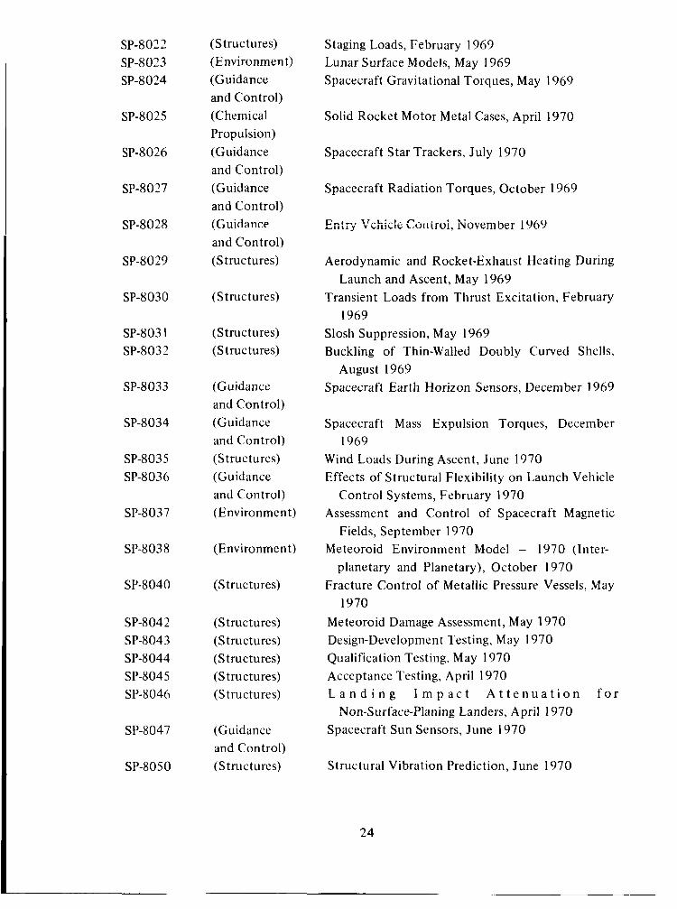
SP-8022 SP-8023 SP-8024
SP-8025
SP-8026
SP-8027
SP-8028
SP-8029
(Structures) (Environment) (Guidance and Control) (Chemical Propulsion) (Guidance and Control) (Guidance and Control) (Guidance and Control) ( S t ru c t u res)
SP-8030 (Structures)
SP-803 1 SP-8032
(Structures) (Structures)
SP-8033
SP-8034
SP-8035 SP-8036
SP-8037
SP-8038
SP-8040
SP-8042 S P-8 04 3 SP-8044 SP-8045 SP-8046
SP-8047
SP-8050
(Guidance and Control) (Guidance and Control) (Structures) (Guidance and Control) (Environment)
(Environment)
( S t ru c t u res)
(Structures) (Structures) (Structures) (Structures) (Structures)
(Guidance and Control) (Structures)
Staging Loads, February 1969 Lunar Surface Models, May 1969 Spacecraft Gravitational Torques, May 1969
Solid Rocket Motor Metal Cases, April 1970
Spacecraft Star Trackers, July 1970
Spacecraft Radiation Torques, October 1969
Aerodynamic and Rocket-Exhaust Heating During
Transient Loads from Thrust Excitation, February
Slosh Suppression, May 1969 Buckling of Thin-Walled Doubly Curved Shells,
Spacecraft Earth Horizon Sensors, December 1969
Launch and Ascent, May 1969
1969
August 1969
Spacecraft Mass Expulsion Torques, December
Wind Loads During Ascent, June 1970 Effects of Structural Flexibility on Launch Vehicle
Control Systems, February 1970 Assessment and Control of Spacecraft Magnetic
Fields, September 1970 Meteoroid Environment M,odel - 1970 (Inter-
planetary and Planetary), October 1970 Fracture Control of Metallic Pressure Vessels, May
1970 Meteoroid Damage Assessment, May 1970 Design-Development Testing, May 1970 Qualification Testing, May 1970 Acceptance Testing, April 1970 L a n d i n g I m p a c t A t t e n u a t i o n f o r
Spacecraft Sun Sensors, June 1970
1969
Non-Surface-Planing Landers, April 1970
Structural Vibration Prediction, June 1970
24
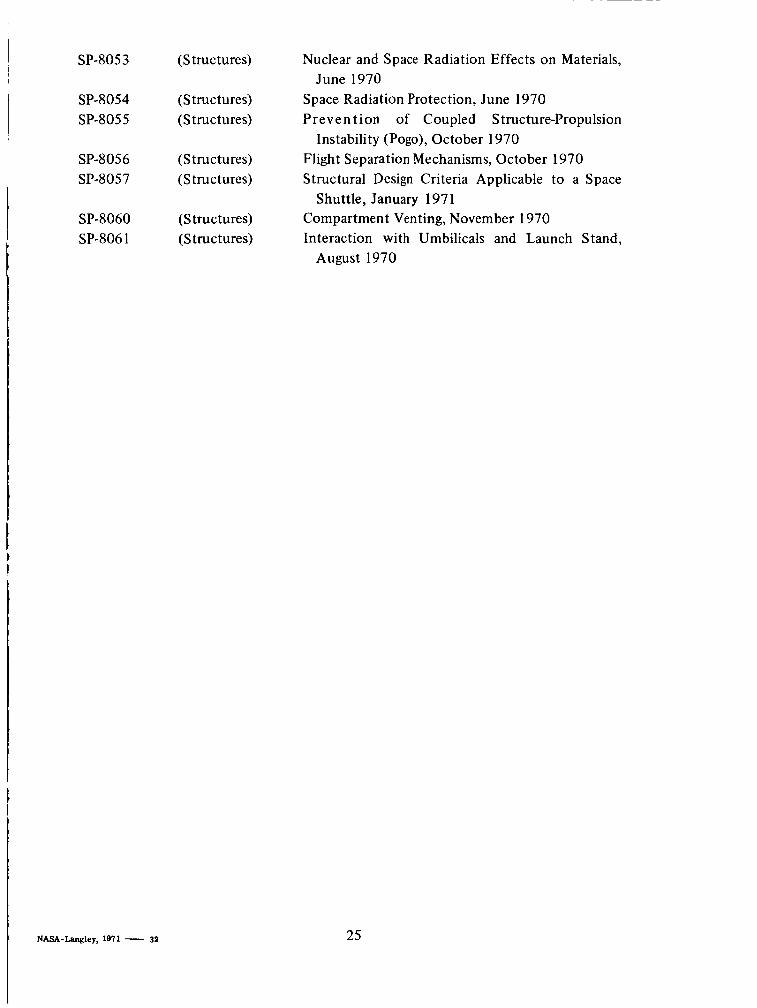
SP-8053 (Structures)
SP-8054 (Structures) SP-8055 (Structures)
SP-8056 (Structures) SP-8057 (Structures)
I
I
SP-8060 (Structures) SP-806 1 (Structures)
Nuclear and Space Radiation Effects on Materials,
Space Radiation Protection, June 1970 Prevent ion of Coupled Structure-Propulsion
Flight Separation Mechanisms, October 1970 Structural Design Criteria Applicable to a Space
Compartment Venting, November 1970 Interaction with Umbilicals and Launch Stand,
June 1970
Instability (Pogo), October 1970
Shuttle, January 197 1
August 1970
I
NASA-Langley, 1971 - 32 25