Embed Size (px)
Citation preview

QUALITY ASSURANCE PROJECT PLAN /
SITE SAMPLING PLAN
LOBECO PRODUCTS REMOVAL INVESTIGATION LOBECO, BEAUFORT COUNTY, SOUTH CAROLINA
Revision 1.0
Prepared for:
U.S. ENVIRONMENTAL PROTECTION AGENCY Region 4
61 Forsyth Street Atlanta, Georgia 30303
Prepared by:
Oneida Total Integrated Enterprises 1220 Kennestone Circle, Suite 106
Marietta, Georgia 30066
Contract No. : EP-W-05-053 Task Order No. : TNA-05-003-0154 Date Submitted : November 17, 2011 EPA Task Monitor : Chuck Berry Telephone No. : 404-562-8278 Prepared by : Lou Von Oldenburg Telephone No. : 678-355-5550

i
REVIEWS AND APPROVALS
CLIENT NAME: U.S. ENVIRONMENTAL PROTECTION AGENCY, REGION 4 CONTRACT NO.: EP-W-05-053
TECHNICAL DIRECTION DOCUMENT NO. TNA-05-003-0154 QUALITY ASSURANCE PROJECT PLAN / SITE SAMPLING PLAN
LOBECO PRODUCTS REMOVAL INVESTIGATION LOBECO, BEAUFORT COUNTY, SOUTH CAROLINA
We the undersigned have read and approve of the quality assurance guidelines presented in this Quality Assurance Project Plan/Site Sampling Plan for work activities at the Lobeco Products Removal Investigation site in Beaufort, South Carolina.
Prepared by: Approved by:
Lou Von Oldenburg START Project Manager
Limari Krebs START Quality Assurance Manager
Chuck Berry EPA Task Monitor/Quality Assurance Manager
ii
DISTRIBUTION LIST
This document will be distributed to the following project participants once all approval signatures have
been received:
Chuck Berry EPA Task Monitor
Katrina Jones,
EPA Project Officer
Sharyn Erickson,
EPA Project Officer
61 Forsyth Street, SW Atlanta, GA 30303
START File, Oneida Total Integrated Enterprises (OTIE)
1220 Kennestone Circle Suite 106 Marietta, GA 30066
iii
CONTENTS Section Page
1.0 INTRODUCTION ........................................................................................................................... 1 2.0 PROJECT ORGANIZATION ....................................................................................................... 2
2.1 EPA START PROJECT OFFICER .......................................................................................... 2 2.2 EPA ON SCENE COORDINATOR ......................................................................................... 3 2.3 START PROJECT MANAGER ............................................................................................... 3 2.4 QUALITY ASSURANCE MANAGER ................................................................................... 4 2.5 LABORATORY RESPONSIBILITIES .................................................................................... 4 2.6 DATA VALIDATION MANAGER ......................................................................................... 5 2.7 FIELD PROJECT LEADER ..................................................................................................... 6 2.8 START SITE SAFETY OFFICER ........................................................................................... 6 2.9 FIELD TECHNICAL STAFF ................................................................................................... 7
3.0 SPECIAL TRAINING/CERTIFICATION .................................................................................. 7 4.0 BACKGROUND ............................................................................................................................. 8
4.1 SITE DESCRIPTION ................................................................................................................ 8 4.2 REGIONAL GEOLOGY AND HYDROGEOLOGY .............................................................. 9 4.3 OPERATIONAL HISTORY ..................................................................................................... 9 4.4 PREVIOUS INVESTIGATIONS ........................................................................................... 11
5.0 PROJECT DESCRIPTION ......................................................................................................... 12 5.1 PROJECT OBJECTIVES ........................................................................................................ 12
5.1.1 Project Target Parameters and Intended Data Usage ........................................................ 12 5.2 TASK DESCRIPTION ............................................................................................................ 12
5.2.1 Task 1 - Perform Project Management and Reporting ..................................................... 13 5.2.2 Task 2 - Develop QAPP/SSP ............................................................................................ 13 5.2.1 Task 3 - Develop Sampling Design .................................................................................. 14 5.2.2 Task 4 - Perform Field Investigation Activities and Data Acquisition ............................. 14 5.2.3 Task 5 – Prepare a RI Report ............................................................................................ 14 5.2.4 Task 6 - Perform TDD Closeout Activities ...................................................................... 14
5.3 DELIVERABLES AND INVESTIGATION SCHEDULE .................................................... 14 5.4 DATA QUALITY OBJECTIVES AND CRITERIA .............................................................. 15
5.4.1 Problem Statement ............................................................................................................ 15 5.4.2 Identify the Decisions ....................................................................................................... 15 5.4.3 Decision Inputs ................................................................................................................. 16 5.4.4 Study Boundaries .............................................................................................................. 16 5.4.5 Decision Rule .................................................................................................................... 16 5.4.6 Error Limits ....................................................................................................................... 17 5.4.7 Optimize Sampling Design ............................................................................................... 17
5.5 MEASUREMENT QUALITY OBJECTIVES ....................................................................... 17 5.6 DATA AND DOCUMENT CONTROL ................................................................................. 18
6.0 SAMPLE DESIGN, DATA GENERATION, AND ACQUISITION ....................................... 19 6.1 SAMPLE DESIGN .................................................................................................................. 19 6.2 FIELD SAMPLING METHODS AND PROCEDURES ....................................................... 19
6.2.1 Mobilization ...................................................................................................................... 19 6.2.2 Site Control and Access .................................................................................................... 19 6.2.3 Site Mapping ..................................................................................................................... 20 6.2.4 Sample Collection ............................................................................................................. 20 6.2.5 Equipment Decontamination Procedures .......................................................................... 21 6.2.6 Management of Investigation-Derived Waste .................................................................. 21 6.2.7 Sample Processing and Custody ....................................................................................... 22 6.2.8 Demobilization .................................................................................................................. 24
6.3 SAMPLE HANDLING AND CUSTODY .............................................................................. 24 6.3.1 Sample Handling ............................................................................................................... 24 6.3.2 Chain of Custody .............................................................................................................. 24
iv
6.4 ANALYTICAL PROCEDURES ............................................................................................ 26 6.4.1 Laboratory Analytical Methods ........................................................................................ 26
6.5 QUALITY ASSURANCE ...................................................................................................... 26 6.5.1 Organization and Responsibilities .................................................................................... 26 6.5.2 Field QA Samples ............................................................................................................. 26 6.5.3 Laboratory QC Requirements ........................................................................................... 27
6.6 INSTRUMENT CALIBRATION AND FREQUENCY ......................................................... 28 6.6.1 Laboratory Instrument Calibration ................................................................................... 28
6.7 INSPECTION/ACCEPTANCE OF SUPPLIES AND CONSUMABLES ............................. 31 6.8 DATA MANAGEMENT ........................................................................................................ 31
6.8.1 Field Data .......................................................................................................................... 31 6.8.2 Laboratory Data ................................................................................................................ 33 6.8.3 Electronic Data Deliverables ............................................................................................ 34
7.0 DATA VALIDATION AND USABILITY .................................................................................. 34 7.1 PROCEDURES USED TO EVALUATE FIELD DATA ....................................................... 34 7.2 PROCEDURES USED TO VALIDATE LABORATORY DATA ........................................ 35
8.0 EXCEPTIONS TO THE ASSIGNMENT OR ANTICIPATED PROBLEMS ....................... 36 9.0 REFERENCES .............................................................................................................................. 37
APPENDICES
APPENDIX A - FIGURES
1 Topographic Map 2 Aerial Map 3 Lobeco Chemical Plant 4 Organizational Chart
APPENDIX B – TABLES
1 Sample Locations 2 Quality Assurance/Quality Control Samples 3 Analytical Methodology, Sample Containers, Preservatives, and Holding Time for Samples 4 Schedule of Deliverables
1
1.0 INTRODUCTION
The U.S. Environmental Protection Agency (EPA) has tasked the Oneida Total Integrated Enterprises,
(OTIE) Superfund Technical Assessment Response Team (START), under Contract Number (No.) EP-
W-05-053, Technical Direction Document (TDD) No. TNA-05-001-0138, to provide the technical
expertise and field personnel to perform field investigation activities in support of a Removal
Investigation (RI) at the Lobeco Products (LP) site located in Lobeco, Beaufort County, South Carolina
(the site). The general purpose of this RI is to collect information and identify the nature and extent of
contamination and to determine the need for federal intervention under the Comprehensive Environmental
Response, Compensation, and Liability Act (CERCLA) of 1980 and the Superfund Amendments and
Reauthorization Act (SARA) of 1986.
Under this TDD, START has been tasked to:
• Develop a Health and Safety Plan (HASP) that includes site-specific health and safety measures for conducting the RI designed to identify volatile organic compound (VOC), semi-volatile organic compound (SVOC), metals, pesticide, polychlorinated biphenyl (PCB), and asbestos contamination at the site;
• Document site conditions and RI activities with written logbook notes and digital photographs;
• Develop a Quality Assurance Project Plan (QAPP)/Site Sampling Plan (SSP) that includes site-specific sampling and analysis procedures and quality assurance measures for conducting an RI designed to identify VOC, SVOC, metals, pesticide, PCB, and asbestos contamination at the site;
• Perform RI activities including waste sampling, field hazard categorization (FHC) testing, environmental sampling for VOCs, SVOCs, metals, pesticides, and PCBs, and sampling debris for asbestos as outlined in the QAPP/SSP; and,
• Prepare a comprehensive report summarizing the site conditions, sampling activities, and analytical results of the RI.
All activities and procedures discussed and described in this QAPP/SSP will be presented and conducted
in accordance with the approved OTIE QAPP and the EPA Region 4 Science and Ecosystem Support
Division (SESD) Field Branches Quality System and Technical Procedures (FBQSTP) (Refs. 1, 2).
This QAPP/SSP documents the policies, project organization, quality assurance (QA) requirements, and
quality control (QC) procedures to be implemented during field activities to ensure the data are valid for
use. This QAPP/SSP combines all EPA requirements for a QAPP (QA-R5) with the elements of a field
SSP so that field and laboratory activities are described in one document (Ref. 3). It defines the QA/QC
methods that must be implemented to ensure data meet the Data Quality Objectives (DQOs). The Health
and Safety Plan (HASP), which is issued as a separate document, defines the preventative and protective
procedures that will be implemented during the field investigation to ensure the safety of the field team.
2
Field activities will include waste and environmental sampling, asbestos sampling and FHC testing.
Analytical services will be provided by an EPA-approved private laboratory and will comply with the
laboratory’s Standard Operating Procedures (SOPs) and the applicable analytical methods required for
this project. The findings of this sampling event will be used to generate an RI report that will then be
used to determine the need for further federal intervention under CERCLA.
The following sections provide the details of this QAPP/SSP:
• Section 2: Describes the proposed project personnel;
• Section 3: Describes the required training/certification of project personnel;
• Section 4: Describes the site background;
• Section 5: Describes the project and objectives;
• Section 6: Describes the sampling design and proposed field activities supporting the sampling event;
• Section 7: Describes the site documentation and data management procedures;
• Section 8: Details the exceptions to the assignment;
• Section 9: Summarizes the proposed field activities supporting the sampling event; and,
• Section 10: Provides references cited to support this document.
Figures and tables are provided in Appendices A and B, respectively.
2.0 PROJECT ORGANIZATION
This section presents the project organization for this field investigation. The organizational structure is
provided in Appendix A, Figure 4.
2.1 EPA START PROJECT OFFICER
The EPA assumes the overall management of this investigation at the request of SCDHEC and the
County of Beaufort (the county). The EPA START Project Officer represents the EPA and is responsible
for:
• Ensuring that EPA guidance and policy is followed and that EPA objectives are achieved during project activities;
• Tracking TDD budgets;
• Reviewing Work Plans;
• Providing incremental funding; and,

3
• Maintaining communication with the EPA On Scene Coordinator (OSC) and START Project Manager (PM).
The EPA START Project Officer is Ms. Katrina Jones.
2.2 EPA ON SCENE COORDINATOR
The EPA OSC directs the project and is responsible for ensuring that the work is completed in accordance
with the requirements of the action memorandum for the site, and for overseeing implementation of the
work required under the TDD. The OSC is also responsible for:
• Maintaining communications with the START PM regarding project status;
• Reviewing Monthly Progress Reports (MPRs);
• Providing oversight of field efforts; and,
• Reviewing all project deliverables prepared by START.
The EPA OSC for this project is Mr. Chuck Berry.
2.3 START PROJECT MANAGER
The START PM is responsible for project performance, budget, and schedule, and for ensuring the
availability of necessary personnel, equipment, subcontractors, and services. The START PM will direct
the development of the field sampling plan, evaluate findings, and prepare the RI report. The START PM
is selected based on technical experience, project needs, and previous START project experience.
Additional responsibilities include:
• Ensuring timely resolution of project-related technical, quality, safety, or waste management issues;
• Functioning as primary interface with the EPA OSC, field and office personnel, and subcontractor points-of-contact;
• Monitoring and evaluating subcontractor laboratory performance;
• Coordinating and overseeing work performed by field and office technical staff (including data validation and report preparation);
• Coordinating and overseeing maintenance of all project records;
• Coordinating and overseeing review of project deliverables;
• Preparing and issuing final deliverables to the EPA; and,
• Approving the implementation of corrective action.
The START PM is Mr. Lou Von Oldenburg.
4
2.4 QUALITY ASSURANCE MANAGER
The QA Manager will be responsible for ensuring that all QA/QC procedures for this project are being
followed. The QA Manager will review and approve the QAPP/SSP. The QA Manager will monitor
sample techniques and collection, and will address any corrective action or issue that may arise with the
analytical laboratory. The QA Manager will also perform internal and external performance and system
audits. The audit process will include, but not be limited to, auditing field sampling techniques. The
EPA Region 4 QA Manager will assure that the QA/QC procedures for this project are being followed on
behalf of the EPA. The START QA Manager, Ms. Limari Krebs, is responsible for reviewing the field
QA sample results to ensure that project DQOs are achieved in accordance with this QAPP. The START
Associate Program Manager, Mr. Russell Henderson, is responsible for auditing field sampling
techniques.
2.5 LABORATORY RESPONSIBILITIES
An EPA-approved and SCDHEC certified laboratory will be procured for this project. The analytical
method list and matrices that will be analyzed for this project are located in Table 3, Appendix B.
The Laboratory PM will communicate directly with the START PM and will be responsible for the
following:
• Efficient delivery of the daily services and support necessary to accommodate the analytical demands of this project;
• Coordination between the network of laboratories for this investigation, if more than one laboratory is procured;
• Coordinating laboratory analyses;
• Supervising in-house chain-of-custody (COC);
• Scheduling sample analyses;
• Overseeing data review and completeness;
• Overseeing preparation of analytical reports; and,
• Approving final analytical reports prior to distribution.
Laboratory QA Officers will be responsible for the following:
• Overview laboratory QA;
• Overview QA/QC documentation;
• Determining whether to implement laboratory corrective actions, if required;
• Conducting detailed data review, if corrective action warrants;
5
• Defining appropriate laboratory QA procedures; and,
• Preparing laboratory SOPs.
Laboratory Sample Custodian responsibilities will include:
• Receiving and inspecting the incoming sample containers;
• Recording the condition of the incoming sample containers;
• Signing appropriate documents;
• Verifying COC and its correctness;
• Notifying laboratory manager and laboratory supervisor of sample receipt and inspection;
• Assigning a unique identification number and customer number, and entering each into the sample receiving log;
• Facilitating sample transfer to analysts who are retrieving and documenting their removal for use in analysis. The sample custodian is also in charge of restocking the sample after they are returned by the analysts, and documents its arrival to keep a record of custody; and,
• Controlling and monitoring access/storage of samples and extracts.
Laboratory Technical Staff will be responsible for sample analysis and identification of corrective actions.
The laboratory will have a Level I/II review process where the analyst reviews the initial data, followed
by a Level II review from a senior analyst. The Laboratory PM reviews for completeness. The QA
Officer will handle any corrective action necessary.
The analytical laboratory will also be responsible for properly disposing of unused sample aliquots.
2.6 DATA VALIDATION MANAGER
The Data Validation Manager is responsible for ensuring that analytical laboratory data are reviewed and
validated in accordance with the project objectives outlined in this QAPP/SSP. The following items
summarize principle areas of responsibility:
• Reviews compliance of the analytical laboratory to methods and analytical requirements as outlined in the QAPP/SSP and laboratory specification;
• Ensures completeness of analytical deliverables both electronic and hardcopy;
• Ensures data validation qualification is conducted in accordance with the EPA National Functional Guidelines (NFG) for Organic and Inorganic analysis requirements;
• Performs a QA review of all validation reports and validated analytical data;
• Reviews and approves all validation qualifications entered into the electronic database;
• Conducts verification and accounting for all samples, analyte fractions, and analytical parameters; and,
6
• Approves final qualified analytical database.
All data validation activities will be performed by Ms. Keely Meadows.
2.7 FIELD PROJECT LEADER
The Field Project Leader (FPL) is responsible for coordinating all on-site personnel, field decisions, and
the overall success of the field investigation. The FPL, or designee, will coordinate and lead all sampling
activities and will ensure the availability and maintenance of all sampling materials/equipment. The FPL
is a highly experienced environmental professional who will report directly to the START PM.
Specific FPL responsibilities include the following:
• Function as communications link between field staff members, Site Safety Officer (SSO), the EPA OSC, and the START PM;
• Oversee the mobilization and demobilization of all field equipment and subcontractors;
• Coordinate and manage the Field Technical Staff;
• Adhere to the work schedules provided by the START PM;
• Be responsible for maintenance of the field logbook and field recordkeeping;
• Initiate field task modification requests when necessary;
• Identify and resolve problems in the field;
• Resolve difficulties in consultation with the EPA OSC; and,
• Implement and document corrective action procedures and provide communication between the field team and START PM.
The FPL for this site is Ms. Amanda Miolen
2.8 START SITE SAFETY OFFICER
The START SSO ensures that the HASP is prepared and implemented during field investigation
activities. The SSO is knowledgeable with Occupational Safety and Health Administration (OSHA) and
EPA Health and Safety requirements.
Specific SSO responsibilities include:
• Monitoring health and safety of the field sampling personnel;
• Assessing hazardous and unsafe situations;
• Developing measures to assure personnel safety during field investigations;
7
• Correcting unsafe acts or conditions through the regular line of authority;
• Exercising emergency authority to prevent or stop unsafe acts when immediate action is required;
• Maintaining awareness of active and developing situations; and,
• Conduct on-site safety meetings.
The START SSO is Mr. Ryan Stubbs (or designee assigned)
2.9 FIELD TECHNICAL STAFF
The Field Technical Staff for this project will be drawn from OTIE’s pool of qualified personnel. Field
personnel are responsible for conducting all field activities according to the requirements presented in this
QAPP/SSP. All of the designated field team members will be experienced professionals who possess the
degree of specialization and technical competence required to effectively and efficiently perform the
required work. The following START personnel will be involved in the field investigation as follows:
• Mr. Ryan Stubbs (or designee assigned) Sampler/FHC
• Jerry Partap (or designee assigned) Sampler/FHC
3.0 SPECIAL TRAINING/CERTIFICATION
Training is required for each individual performing activities in support of environmental data collection
or analysis. The OTIE Human Resources (HR) Department maintains an individual file for each OTIE
employee who includes certificates for 40-hour hazardous waste operations and emergency response
(HAZWOPER) and 8-hour refresher training records.
The laboratory performing analytical services must hold certification by SCDHEC and/or the National
Environmental Laboratory Accreditation Program (NELAC) as a requirement for this project. In
addition, the laboratory manager is responsible for ensuring that personnel training are current and
documented as defined in the laboratory’s SOPs. It is the laboratory’s manager’s responsibility to
determine specific training and certification needs, and for ensuring that any required training is
documented.
Individuals implementing this QAPP/SSP must receive, at a minimum, orientation to the project’s
purpose, scope, and methods of implementation. This orientation is the responsibility of the PM or
designee. Any field team members involved with sample collection or handling will have received 40-
8
hour HAZWOPER – 29 CFR 1910.120 training and their 8-hour HAZWOPER refresher up to date. The
Health and Safety Officer will have received 8-hour supervisor training course (HAZWOPER – 29 CFR
1910.120). Any other safety-related training is defined in the project HASP.
4.0 BACKGROUND
The following sections provide background information to provide a historical, scientific, and regulatory
perspective for this project.
4.1 SITE DESCRIPTION
The LP site is located at 23 John Meeks Way in Lobeco, Beaufort County, South Carolina (Appendix A,
Figures 1 and 2). The property includes 125 acres of land surrounded by agricultural, rural residential,
and undeveloped property. Most of the site is currently owned by Coastal Demolition, although portions
of the property are owned by other parties (Ref. 4).
The site’s latitude is 32.555753o north and the longitude is -80.729317o west and the closest cross road is
Keans Neck Road, located to the northeast. It’s located on FEMA’s flood insurance rate map
4500250040D and is rated as Flood Zone C. The commercial property ID is recorded as R700 037 000
0017 and its legal description is listed as:
TRACT 1 DORMANT LAND ASSESSED BY SCDOR 607 00094 FILE#60700125 LOBECO PRODUCTS *SPLIT
10/90 4.93 AC 37/17B *CORPORATE NAME CHG DB1735 P579 *4/10 9.16 AC MERGED FROM 37/94 PB128
P16 *4/10 SPLIT 121.04 AC 37/181-186, 188 *4/10 SPLIT 33.49 AC 37/187 PB128 P21 DORMANT LAND
ASSESSED BY SCDOR 607 00094 FILE#60700125 LOBECO PRODUCTS
Currently the site maintains a portion of the chemical processing structures, a storage/warehouse, a lab
testing area, offices and the waste water treatment facility. Part of the processing facility has been
demolished but the rubble remains onsite; there is concern for asbestos in the demolition debris. The site
is bordered to the north and west by undeveloped property owned by the Community Development
Corporation of Beaufort County, and several site features, including the large parking lot, the most
northeastern building, and the electronic gate are actually on property owned by the Community
Development Corporation of Beaufort County. To the east are several single-family residences. To the
south, the site is bordered by Morgan Road (also known as State Road S-7-301), which is immediately
adjacent to the Huspa Creek tidal flats.
9
4.2 REGIONAL GEOLOGY AND HYDROGEOLOGY
The Natural Resource Conservation Service (NRCS) soil survey lists the dominant soil type at the site as
Yemassee loamy fine sand (Ye) with a zero to two percent slope (Ref 5). The report also lists the mean
annual precipitation to be from 45 to 52 inches, and the mean annual air temperature to be 64 degrees
Fahrenheit (º F) to 70º F. The parent soil material is comprised of loamy marine deposits, and is a
considered a somewhat poorly drained soil. The typical profile is listed as zero to fifteen inches of loamy
fine sand underlined by fine sandy loam. The typical depth to water table is between twelve and eighteen
inches below ground surface (bgs). The Soil Survey of Beaufort and Jasper Counties, South Carolina
reports the profile of the surface soil is dark gray loamy fine sand and the subsurface soil will be light
yellowish-brown loamy fine sand, commonly found within the Lower Coastal Plain region (Ref. 6).
According to the NRCS soil survey, additional soil types at the property include Tomotley loamy fine
sand (To) and Chisolm loamy fine sand (CmB). Tomotley loamy fine sand also has a zero to two percent
slope, parent soil material that is comprised of loamy marine deposits, and is a poorly drained soil. The
typical profile is listed as zero to thirteen inches of loamy fine sand underlined by sandy clay loam and
sandy loam. The typical depth to water table is between zero and twelve inches below ground surface
(bgs). The Soil Survey of Beaufort and Jasper Counties, South Carolina reports the profile of the surface
soil is dark gray loamy fine sand, and red, olive, and/or brown mottles can be observed with depth.
The Chisolm loamy fine sand has a zero to six percent slope, parent soil material that is comprised of
loamy marine deposits, and is considered a somewhat excessively drained soil. The typical profile is
listed as zero to twenty-five inches of loamy fine sand underlined by sandy clay loam and fine sandy
loam. The typical depth to water table is between thirty-six and sixty inches below ground surface (bgs).
The Soil Survey of Beaufort and Jasper Counties, South Carolina reports the profile of the surface soil is
grayish-brown to pale brown sand, and the subsurface is comprised of yellowish-red sandy clay loam with
red, brown and/or gray mottles observed with depth (Refs. 5, 6).
4.3 OPERATIONAL HISTORY
The LP site operated as a specialty chemical manufacturer for more than 40 years (1966 to 2009). The
product lines included dyes, farm chemicals, drilling fluid chemicals, and general specialty chemicals.
The property has been abandoned since December of 2010, with power off to most or all of the property.
10
The site was initially owned by Tenneco Chemicals, Inc. The Tenneco Chemicals Berkshire Color
Division constructed the plant for the production of dyestuff intermediates in 1967. Prior to that time the
property was farmland and had not been subject to any industrial or commercial use. From 1974 to 1982
ACC owned the facility and operated as a manufactured chemical facility; the exact chemicals produced
are unknown. From 1982 to 1989 the property was owned by Venture Chemicals (a.k.a. Lobeco
Products). Venture Chemicals historically worked with basic cellulose and lignite derivatives. From
1989 to 1998 the site was owned by Compagnie Francaise des Produits Industriels (CFPI). CFPI was a
manufacturer of agrochemicals, surfactants and other specialty industrial chemicals. One of their
products was a granulation aid and anti-caking agent for fertilizers - particularly ammonium nitrate.
NuFarm acquired CFPI stock in 1998 and owned the facility from 1998 to 2005. NuFarm also worked
with chemicals and chemical preparation, particularly pesticides, herbicides and fungicides. From 2005
to 2009 the facility was owned by ARR-MAZ Custom Chemicals Inc, known for pesticides and
agricultural chemicals. After ARR-MAZ the facility was shut down and sold at auction to Coastal
Demolition. Coastal Demolition recovered an unknown amount of scrap from the facility, demolishing
the reactor building in the process. No chemicals were reported to have left the facility during Coastal
Demolition’s operation.
While operating under Tenneco the facility used Monsanto Corporation’s Aroclor 1248 PCB product.
The Aroclor 1248 was used as a heat transfer oil. During the process of producing its J-Acid, a dyestuff
intermediate, raw material had to be interacted at very high temperatures. The high temperatures were
attained by the use of a heat transfer oil in a hot oil reactor system. Aroclor 1248, a PCB oil, was used in
that system.
The hot oil system in which Aroclor 1248 was used malfunctioned at times. On these occasions the
heating elements would blow out resulting in discharges of PCBs into the Lobeco drainage system. The
quantity ranged from a few gallons to 300 gallons, the entire capacity of the system. Also in order to
replace blown out elements, the entire hot oil system had to be drained. When the change out occurred,
sometimes the oil would leak into the drainage system and straight into the holding lagoons or the ground.
Untreated liquids from the lagoon were discharged directly into Whale Branch, which flows into
Campbell Creek, and ultimately the Atlantic Ocean.
During a court case of American Color & Chem. Corp. v. Tenneco Polymers, it was revealed that when
the facility was operated under Tenneco it utilized an isolated burn site on the outer reaches of its Lobeco
property for the burial of used drums, off-spec material, and paper and metal refuse. Reportedly, Aroclor
1248 was released into the burn site area during Tenneco’s ownership of the plant.
11
4.4 PREVIOUS INVESTIGATIONS
In 1983 SC DHEC conducted an in-stream assessment of Campbell Creek and Whale Branch. A follow
up SC DHEC study in December 1984 revealed the presence of PCBs in the immediate vicinity of the
Lobeco plant effluent discharge point. As a result of this finding Davis & Floyd Engineering conducted
groundwater testing and produced a groundwater monitoring report which revealed the presence of PCBs
at the Lobeco Plant.
Based on this information Tenneco Products commissioned further tests in order to characterize the extent
and location of the PCB problem at the Lobeco Plant. Initial soil borings indicated the presence of PCBs
in the abandoned lagoon.
In 1986 G & E Engineering, hired by SC DHEC, issued a preliminary investigation report pinpointing the
location of the PCB contamination at the lagoon and burn site areas. In 1987, under the first of three SC
DHEC consent orders, cleanup of the PCBs commenced. RMT of Greenville was chosen as the contractor
for the remediation, dig and haul. An exact date of the completion of the dig and haul remediation was
not found, however the final report was produced in November 1991. Under the second consent order
there was still a concern for PCB impact and cited a need to define the horizontal and vertical extent of
groundwater contamination. A well survey of residential wells was performed and found no PCB
contamination of groundwater existed in the neighboring wells. No further information could be found at
this time.
The current investigation is not focused on these areas, however, and is instead focused on the remaining
bulk wastes on site, both in above-ground -containers and in surface impoundments, as well as on-site soil
in operational areas of the site, specifically the now demolished reactor building.
12
5.0 PROJECT DESCRIPTION
5.1 PROJECT OBJECTIVES
The scope of this removal investigation is to conduct sampling and analysis as well as FHC testing
activities at the site to 1) identify any hazardous wastes which may be remaining at the site in containers,
tanks, drums, surface impoundments, or other bulk storage containers, and 2) identify any impacts to site
soil or surface impoundment sludges resulting from historical releases of CERCLA hazardous substances.
All sampling activities will be conducted in accordance with the SESD FBQSTP (November 2007).
Samples will be collected from all above-ground bulk storage containers 55-gallons or greater. Smaller
containers may be sampled if time permits. The contents will undergo FHC testing on-site in order to
determine if the material contains any characteristically hazardous waste as well as testing for bulking and
disposal purposes. Samples from wastewater surface impoundments will also be collected to determine if
the water or sludge pose a threat to human health and if it meets any of the definitions of hazardous waste
given in 40 CFR 261. The analytical data gathered during this field investigation will provide EPA with
sufficient information to determine the need for further federal intervention under CERCLA.
5.1.1 Project Target Parameters and Intended Data Usage
Table 3 in Appendix B summarizes the laboratory methods that will be conducted for, sludge, and bulk
asbestos sampling.
All analytical data will be reported to the analyte’s laboratory-specific method detection limit (MDL); i.e.,
positive results below the RL but greater than the MDL will be reported by the laboratory and flagged as
estimated (J). MDLs will be adjusted on a sample-by-sample basis, as necessary, based on dilutions,
sample volume, and percent moisture.
Waste samples will be subjected to field hazard characterization testing, which will collect qualitative,
rather than quantitative, data. These data will be used to group like chemicals together for subsequent
compositing and analysis. Laboratory analytical data will be used to determine if the material meets any
of the definitions of hazardous waste as defined in 40 CFR 261.
5.2 TASK DESCRIPTION

13
The following subsections discuss tasks that START will perform to complete this work assignment
allowing for modifications, as needed.
• Task 1 - Perform Project Management and Reporting
• Task 2 - Develop QAPP/SSP
• Task 3 – Develop Sampling Design
• Task 4 - Perform Field Investigation Activities and Data Acquisition
• Task 5 - Prepare Field Investigation Report
• Task 6 - Perform TDD Close-Out Activities
The schedule by which START anticipates conducting/completing the tasks under this work assignment
is listed in Table 4 located in Appendix B.
If the statement of work changes because of an amended work assignment, START will revise this
QAPP/SSP to incorporate changes in the scope and cost.
5.2.1 Task 1 - Perform Project Management and Reporting
START will perform general TDD management activities including communications with the EPA OSC,
managing and tracking costs using Removal Cost Management System (RCMS), and attending project
meetings. The anticipated period of performance for this project is from October 27, 2011 through April
27, 2012. Specifically, START will prepare MPRs in accordance with contract requirements; track costs
in RCMS and submit 1900-55 Daily Contractor Cost Report forms as directed by the EPA OSC; and
prepare and submit monthly invoices. START will report costs and level of effort for the reporting period
as well as cumulative amounts expended to date.
5.2.2 Task 2 - Develop QAPP/SSP
This QAPP/SSP has been developed to outline activities to be conducted in support of the RI. The
QAPP/SSP lists the tasks to be performed; discusses the technical approach for each task, including
identifying DQOs, determining sampling objectives and rationale for the field investigation activities, and
ensuring that QA/QC measures are conducted to fulfill DQOs; identifies key personnel to support this
work assignment; and provides a schedule for completing each task and submitting deliverables as
required by the TDD. START has reviewed available background documents relevant to the
investigation, as provided by the EPA, in order to achieve a familiarity with the site and support the
development of the tasks.
14
All efforts will be made to provide the most cost-effective approach to supporting EPA in this work
assignment. The QAPP/SSP will be amended as necessary to incorporate unforeseen future activities or
changes in the scope of the work assignment.
5.2.1 Task 3 - Develop Sampling Design
START will develop a sampling design in accordance with the EPA Guidance on Choosing a Sampling
Design for Environmental Data Collection (QA/G-5S) to ensure that DQOs are fulfilled for the RI (Ref.
7). Specifically, the design will take into account data needs, key decisions, and environmental variables,
such as physical and site constraints, and how the spatial and temporal boundaries of the contamination
and population at risk will be identified. The sampling design presented in Section 6.1 has been
developed based on the results of an initial site walk, and input from the TM.
5.2.2 Task 4 - Perform Field Investigation Activities and Data Acquisition
START will perform field investigation activities including sampling and FHC testing. The data will
provide EPA with sufficient information to identify the need for federal intervention under CERCLA.
This task will begin with EPA approval of this QAPP/SSP and will end with the demobilization of field
personnel and equipment from the site.
5.2.3 Task 5 – Prepare a RI Report
START will prepare a RI Report summarizing the existing conditions at the site, describing the field
investigation activities, and describing the contamination at the site. The RI Report will provide
information to assess immediate risks to human health and the environment. Environmental and QA/QC
analytical data will be evaluated and data tables will be attached to the report. Significant QA/QC issues
regarding sample collection, handling, and analysis will be identified in the report.
5.2.4 Task 6 - Perform TDD Closeout Activities
START will perform the necessary activities to close out the TDD in accordance with the contract
requirements including packaging and returning documents to the U.S. government and duplicating,
distributing, and storing files, as necessary.
5.3 DELIVERABLES AND INVESTIGATION SCHEDULE
15
The schedule by which START anticipates submitting the associated deliverables under this work
assignment is listed in Table 4 located in Appendix B.
5.4 DATA QUALITY OBJECTIVES AND CRITERIA
START has identified DQOs for the site in accordance with the EPA Guidance for the DQO Process,
(U.S. EPA QA/G-4, 2006), that will define study objectives, decisions to be made, and the criteria by
which the data will be assessed (Ref. 8). These data will then be used for decision making. Upon
completion of the work described throughout the QAPP/SSP, the data collected will be compared to the
established DQOs to ensure that the information collected meets the intended goal of the work. DQOs
have been developed following these seven steps:
• Problem statement
• Identify the decisions
• Identify the inputs into the decision
• Define the boundaries of the study
• Develop decision rules
• Specify tolerable limits on decision errors
• Optimize the design for obtaining data
The information presented in the next several sections describes the DQOs identified for this assessment.
5.4.1 Problem Statement
A former custom-chemical manufacturing plant has been abandoned, and there is a potential for a release
of hazardous substances, pollutants, or contaminants into the environment from drums, tanks, or other
containers on site.
5.4.2 Identify the Decisions
This investigation will focus on 1) determining if material stored in containers and water and sludge in the
wastewater treatment ponds could be classified as characteristically hazardous waste, and 2) determining
the presence or absence of contamination in and around the former manufacturing areas of the site,
including the debris pile in the area where the reactor building once stood. Therefore, the following
primary decisions have been identified:
16
1. Do the contents of ASTs, vessels, drums, totes, and wastewater surface impoundments meet the
definition of hazardous waste as defined at 40 CFR 261?
2. Does the level of contamination warrant further EPA involvement?
5.4.3 Decision Inputs
The primary input needed to support the decision making process is reported analytical concentrations of
contamination in waste, wastewater, and sludge samples collected from the site. Analytical results used
in the decision-making process will come from Target Compound List (TCL) VOCs, TCL SVOCs, TCL
pesticides, PCBs, TAL metals, asbestos, and FHC results. Laboratory analysis of the samples collected
on site will be performed by an EPA-approved private laboratory.
5.4.4 Study Boundaries
The media of interest include on-site sludges and debris piles. The study boundaries include the study
area, sample depth, temporal boundaries such as field investigation dates and turnaround times on
analytical results, and physical boundaries.
• The study area is the boundary of the site as shown in Figures 1 and 2 located in Appendix A.
• Samples from on-site ASTs, vessels, drums, and totes will be collected and assessed using FHC procedures to determine if characteristically hazardous waste is present.
• Sediment samples will be collected from the wastewater treatment impoundments and submitted to the laboratory for VOC, SVOC, metals, pesticide, and PCB analysis.
• Wastewater samples will be collected from the wastewater treatment impoundments and submitted to the laboratory for VOC, SVOC, metals, pesticide, and PCB analysis.
• Various solid samples collected on-site from debris piles will be submitted to the laboratory for asbestos analysis.
• Field investigation activities are scheduled to commence the week of January 17, 2012. Field investigation activities are expected to last one week. A standard turnaround time will be requested for final analytical results from the laboratory. An additional 6 weeks will be necessary to perform data validation activities.
5.4.5 Decision Rule
The primary decisions in the DQO process for the site are: (1) Are the contents of the containers and
wastewater surface impoundments characteristically hazardous? (4) Is there asbestos in the debris pile
which may pose a threat to persons working in the area?
Waste samples will be collected and submitted to a certified laboratory for VOCs, SVOCs, TAL metals,
pesticides, and PCBs. In addition, various solid samples will be collected on-site and submitted to a
17
certified laboratory for asbestos analysis. Analytical and screening results will be used to determine if
contaminants of concern exist on site and whether federal invention under CERCLA is needed.
5.4.6 Error Limits
Sections 6.2.4 and 6.2.7 will describe the error limits introduced through sample collection, mixing,
storage, transportation, and analysis.
5.4.7 Optimize Sampling Design
The data collection activities will focus on identifying the presence or absence of contamination in several
study areas. Section 6.1 will describe the sampling design in detail.
5.5 MEASUREMENT QUALITY OBJECTIVES
Measurement quality objectives can be expressed in terms of precision, completeness, and sensitivity
goals. Precision are monitored through the analysis of QC samples (Section 6.5.2). Completeness is a
calculated value. Sensitivity is monitored through instrument calibration and the determination of MDLs
and RLs. Qualitative quality objectives, expressed in terms of comparability, are not addressed as part of
this sampling design since sampling locations are biased and not random.
• Accuracy is defined as the degree of agreement between an observed value and an accepted reference value. Accuracy shall be measured through the collection of blanks, performance evaluation samples, and blind spike samples.
• Precision is defined as degree to which a set of observations or measurements of the same property, obtained under similar conditions, conform to themselves. Precision shall be measured through the collection of duplicate field samples.
• Completeness is the amount of data collected as compared to the amount needed to ensure that the uncertainty or error is within acceptable limits. The goal for data completeness is 100%. However, the project will not be compromised if 99% of the samples collected are analyzed with acceptable quality.
• Representativeness is the degree to which data accurately and precisely represent a characteristic of a population. This is a qualitative assessment and is addressed primarily in the sample design, through the selection of sampling sites and procedures that reflect the project goals and environment being sampled. It is ensured in the laboratory through (1) the proper handling, homogenizing, compositing, and storage of samples and (2) analysis within the specified holding times so that the material analyzed reflects the material collected as accurately as possible.
• Sensitivity is the capability of a test method or instrument to discriminate between measurement responses representing different levels (e.g., concentrations) of a variable of interest. Sensitivity is addressed primarily through the selection of appropriate analytical methods, equipment, and instrumentation. The methods selected for this assessment were chosen to provide the sensitivity required for the end-use of the data. This is a quantitative assessment and is monitored through
18
the instrument calibrations and calibration verification samples and the analysis of procedural blanks with every analytical batch.
• Method Detection Limits (MDLs) for all analyses will be those identified through SW-846 methods.
• Reporting Limits (RLs) for all analysis are based on a low calibration standard and are described in each analytical method identified above. Sample-specific reporting limits will be calculated and reported with the final data. There may be numbers reported that are below the RL. These numbers must be flagged appropriately. When the analysis demonstrates a non-detect at the MDL, the data shall be flagged with a “U.” The value reported is the MDL, adjusted by any dilution factor used in the analysis. When an analyte is detected between the lower quantitation limit and the MDL, the data shall be flagged with a “J.” The value reported is an estimate.
5.6 DATA AND DOCUMENT CONTROL
START will maintain logbook notes and collect digital photographs during the sampling event. START
will use this information to complete a RI Report summarizing the existing conditions at the site, the field
investigation activities, and the nature of contamination at the site. Environmental and QA/QC analytical
data will be evaluated and data tables will be attached to the report. Significant QA/QC issues regarding
sample collection, handling, and analysis will be identified in the report.
The OTIE internal QC process requires that all project deliverables be reviewed to promote technical
adequacy and completeness. The OTIE QA manager or designee will perform internal QC checks of
work assignment activities. Internal QC checks will address adherence to this QAPP and the OTIE QAPP
for START.
START will retain all file information related to the site in the Marietta, Georgia, OTIE office. Upon
EPA request, the entire site file, including all documents generated under the work assignment, will be
inventoried and submitted to EPA or to an EPA-designated location within three weeks of the request. In
addition, START will provide digital copies of all documents generated under the work assignment,
including reports, e-mails, and figures if requested by EPA. All documents generated for the work
assignment are the property of EPA and will be retained as part of EPA files. All EPA files will be
delivered to EPA at the conclusion of the START contract.
A draft version of the report will be available for review and commenting by EPA within 28 days
following receipt of final analytical results from the laboratory. A final version of the report will be
available within two weeks following receipt of comments by EPA. Laboratory data will be released to
the EPA OSC as it becomes available, if desired. Table 4 in Appendix B lists the schedule for the
deliverables and investigation.
19
6.0 SAMPLE DESIGN, DATA GENERATION, AND ACQUISITION
This section of the report discusses the purpose of the sampling event, sampling procedures, a description
of tasks associated with the RI, schedule of deliverables, laboratory data management, data quality
control, and data validation.
6.1 SAMPLE DESIGN
START has developed a sampling design to ensure that DQOs are fulfilled for the sampling investigation.
Specifically, the design takes into account data needs, key decisions, and environmental variables, such as
physical and site constraints, and how the spatial and temporal boundaries of the contamination and
population at risk will be identified. The sampling design presented in the following sections has been
developed based on available information from SCDEHC and previous site activities.
Approximately 10 sludge samples, 10 water samples, 5 waste stream samples, eight aboveground storage
tank samples and 5 suspect asbestos containing material (ACM) debris samples. Tables 1-3, located in
Appendix B, identify the sample analysis, sample numbers, and types of samples proposed.
Sampling locations may change during the field investigation based on field observations by the EPA
OSC.
6.2 FIELD SAMPLING METHODS AND PROCEDURES
The following section details sample collection methods and equipment for waste, sludge, and debris
sampling, sample preservation requirements, and decontamination procedures.
6.2.1 Mobilization
START will provide the necessary personnel, equipment, supplies, materials, and facilities for the
execution of the field investigation. Activities may include the mobilization of equipment and vehicles,
and site access coordination with federal, state, local, and private entities.
6.2.2 Site Control and Access
The site is secured and any problems with unauthorized personnel accessing the site operations are not
anticipated. However, if at any time, investigation activities cannot, in the opinion of the FPL/SSO, or
20
sample team members, be conducted due to the proximity of unauthorized persons or other unforeseen
conditions or situations, then operations will cease until such time as they can be safely resumed.
During the investigation, field vehicles will be located such that they do not interrupt or impede flow of
traffic through the area. Keys to each vehicle will be located with team leaders, as appropriate. Each
field vehicle will maintain a copy of this QAPP/SSP and the site specific HASP during all investigation
activities.
6.2.3 Site Mapping
The location of all sampling stations will be collected using a Trimble® Global Position System (GPS)
instrument. GPS coordinates will be collected at each sampling location during the field event. As
specified in FBQSTP Global Positioning System procedure (SESDPROC-110-R3), stations will be
located with one meter accuracy. If a location is in an area where a GPS signal cannot be received, the
GPS of sampling locations will be collected from the nearest point where a signal is received and any
deviations noted in the field logbook.
6.2.4 Sample Collection
Waste, wastewater/sludge, and debris sampling will be conducted to assess the extent of potential
contamination. In short, in the onsite waste water treatment plant area the two aeration tanks will be
sampled for sludge and water column, the four clarifiers will be samples for sludge and water column,
and the basins will be sampled for sludge and water column. A composite sample from the eight pH
adjustment totes will be sampled, the miscellaneous unknown drums and totes will be tested and
compiled and an aliquot of the waste stream will be sampled. The random aboveground storage tanks will
be checked for product and tested. Also several suspect ACM will be sampled along with an air sample
from a personal air monitor.
The sludge and sludge samples will be submitted for laboratory analysis of VOCs, SVOCs, pesticides,
PCBs, and TAL metals based on the study area investigated. In addition, the debris samples will be
submitted for laboratory analysis of asbestos. Table 3, located in Appendix B, specify the analyses
identified for each field sample. Approximately 2 additional QA/QC sample duplicates will be collected
as required in FBQSTP Field Sampling Quality Control (SESDPROC-011-R3). All samples collected
will be immediately preserved in accordance with FBQSTP Sample and Evidence Management
(SESDPROC-005-R1) guidelines.

21
Sludge Sampling
A grab sludge sample will be collected from the bottom of the AST, vessel, or other sludge filled vessel
using a sludge judge, ponar dredge or other dredging device. The sample will be placed in a
decontaminated stainless steel bowl, and decontaminated stainless steel spoons will be used to place the
sample in the appropriate containers for laboratory analysis. Samples will be preserved and placed on ice
in accordance with the FBQSTP Sample and Evidence Management (SESDPROC-005-R1) guidelines.
All field observations and descriptions will be recorded in the logbook.
Debris Sampling
A grab solid sample will be collected from the debris pile located on-site using a gloved hand. The
sample will be containerized, preserved and placed on ice in accordance with the FBQSTP Sample and
Evidence Management (SESDPROC-005-R1) guidelines.
All field observations and descriptions will be recorded in the logbook.
6.2.5 Equipment Decontamination Procedures
All field sampling equipment will be cleaned and decontaminated in accordance with the FBQSTP Field
Equipment Cleaning and Decontamination procedures (SESDPROC-205-R1).
6.2.6 Management of Investigation-Derived Waste
All investigation derived waste (IDW) will be managed according to the procedures found in the
FBQSTP Management of Investigation-Derived Waste procedure (SESDPROC-202-R1). The following
identifies the types of IDW that could be generated during the investigation. IDW will generally consist
of personal protective equipment and used disposable sampling equipment. All IDW will be secured in a
55-gallon drum on site, until sample analytical results are received. If, in the best professional judgment
of the FPL, personal protective equipment can be rendered non-hazardous, it will be double-bagged and
deposited in an industrial waste container, as directed in the FBQSTP SESDPROC-202-R1. All field
sampling equipment will be cleaned and decontaminated according to the FBQSTP Field Equipment
Cleaning and Decontamination procedures (SESDPROC-205-R1).
22
6.2.7 Sample Processing and Custody
All samples will be collected, containerized, preserved, handled, and documented in accordance with the
EPA FBQSTP and the EPA CLP Guidance for Field Samplers (CLPGFS) dated July 2007. The
following activity procedures will be followed during field sampling:
• Sample and Evidence Management SESDPROC-005-R1
• Equipment Inventory and Management Procedure SESDPROC-108-R3
• Packing, Marking, Labeling, and Shipping of Environmental and Waste Samples SESDPROC-209-R1
Both hard and electronic copies of the referenced procedures, in addition to the site-specific HASP, will
be maintained by the FPL for reference during all phases of the field sampling activities. Any deviations
in sampling procedures specified in this QAPP/SSP will be documented, including the reason for the
deviation, in the field logbooks.
Chain of Custody
All Chain-of-Custody (COC) and record keeping procedures will be in accordance with FBQSTP
SESDPROC-005-R1 and the CLPGFS. COC procedures are comprised of the following elements: 1)
maintaining sample custody, and 2) documentation of samples for evidence. COC forms will be
completed and generated with Scribe software as per the current START contract requirements.
Station and Sample Identification
Station IDs will be assigned as follows:
• LP01 – LP21, where LP stands for Lobeco Products RI and the stations are numbered sequentially.
Sample identification numbers will be assigned using the following format:
• LP-SS-## • LP-DP-##
LP stands for Lobeco Products RI, the SS stands for sludge sample, DP stands for debris pile, and the ##
is the sample number beginning at -01.

23
Sample Labels
Sample labels will be prepared and affixed to each sample container sent to the laboratory. The labels
will be prepared using waterproof, non-erasable ink as specified in FBQSTP SESDPROC-005-R1 and
CLPGFS. Sample labels will be generated with Scribe software as per the current START contract
requirements.
Sample Custody Seals
The samples collected and containerized will be sealed as soon as possible following collection as
specified in the FBQSTP SESDPROC-005-R1 and CLPGFS. The sample custodian will write the date
and their signature or initials on the seal.
Sampling Equipment and Sample Containers
Sampling equipment used during the field investigation will include a ponar dredge, a sludge judge,
stainless steel spoons, and stainless steel bowls. The ponar dredge, sludge judge, spoons, and bowls will
be decontaminated in accordance with FBQSTP SESDPROC-205-R1 prior to mobilization to the site.
All associated non-dedicated/reusable (ponar dredge, sludge judge, spoons, and bowls) equipment will be
decontaminated as necessary during the sampling event in accordance with FBSQTP. All equipment will
be handled in accordance with the FBQSTP Equipment Inventory and Management procedure
(SESDPROC-108-R3).
Sample containers for samples submitted to the private laboratory will be obtained from the private
laboratory. All samples will be placed into QC-quality glass jars, and placed on ice in accordance with
the requirements specified in the FBQSTP SESDPROC-209-R1 and CLPGFS.
Custody Procedures
The field COC is used to record the custody of all samples sent to the laboratory. All samples shall be
accompanied by a COC, completed and maintained as specified in FBQSTP SESDPROC-005-R1. The
COC documents transfer of custody of samples from the sample custodian to another person, the
laboratory, or other organizational elements. To simplify the COC and eliminate potential litigation
problems, as few people as possible will have custody of the samples or physical evidence during the
investigation.
The COC also serves as a sample logging mechanism for the laboratory sample custodian. Scribe
software will be used to log samples and create a COC for all samples or physical evidence collected. A
separate COC will be used for each final destination or laboratory utilized during the investigation.
24
6.2.8 Demobilization
START will remove all equipment and restore all site sampling locations which may have been disturbed
during the field investigation.
6.3 SAMPLE HANDLING AND CUSTODY
All samples will be containerized, preserved, handled, and documented in accordance with the EPA
FBQSTP SESDPROC-005-R1.
6.3.1 Sample Handling
Information identifying the location and date/time will be inscribed on each container. After the samples
are containerized, they will be placed on ice (maintaining a sample temperature of 4°C), processed (see
below), packaged for shipment in accordance with FBSQTP Packing, Marking, Labeling, and Shipping of
Environmental and Waste Samples (SESDPROC-209-R1), and transported to a private laboratory for
analysis via FedEx.
Sample Labels
Sample labels will be prepared and affixed to each sample container sent to the private laboratory. The
labels will be prepared using waterproof, non-erasable ink as specified in FBQSTP SESDPROC-005-R1.
Sample Custody Seals
The samples collected and containerized will be sealed as soon as possible following collection as
specified in the FBQSTP SESDPROC-005-R1. The sample custodian will write the date and their
signature or initials on the seal.
6.3.2 Chain of Custody
COC Record
The field COC Record is used to record the custody of all samples sent to the laboratory. All samples
shall be accompanied by a COC Record, completed and maintained as specified in FBQSTP
SESDPROC-005-R1. To simplify the COC Record and eliminate potential litigation problems, as few
people as possible will have custody of the samples or physical evidence during the investigation.

25
The COC Record also serves as a sample logging mechanism for the laboratory sample custodian. A
separate COC Record will be used for each final destination or laboratory utilized during the
investigation.
COC Procedures
COC procedures are comprised of the following elements: 1) maintaining sample custody and 2)
documentation of samples for evidence. A sample file is under custody when any one of the following
conditions is satisfied:
• The item is in the actual physical possession of an authorized person.
• The item is in view of the person after being in his or her possession.
• The item was placed in a secure area to prevent tampering.
• The item is in a designated and identified secure area with access restricted to authorized personnel only.
Field Custody Procedures
The FPL (or designee) is responsible for the care and custody of the samples collected until they are
relinquished to the laboratory or entrusted to a commercial courier. Custody procedures apply to all
environmental and associated field QC samples obtained as part of the data collection system. When
transferring samples, the individuals relinquishing and receiving the samples will sign, date, and note the
time on the COC record. The original record will accompany the shipment and the field sampler will
retain a copy. This record documents the sample custody transfer from the sampler to the laboratory,
often through another person or agency (common courier). After COC records have been placed within
sealed shipping coolers, the signed courier airbills will serve to document COC. Upon arrival at the
laboratory, internal laboratory sample custody procedures will be followed (see below).
Laboratory Custody Procedures
Laboratory custody procedures will ensure that sample integrity is not compromised from the time of
receipt at the laboratory until final data are reported to EPA and START. This requires that the laboratory
control all sample handling and storage conditions and circumstances.
Laboratory custody procedures for sample receiving and log-in; sample storage and numbering; tracking
during sample preparation and analysis; and storage of data are described in laboratory SOP. In general,
upon laboratory receipt of a shipment of samples, the laboratory's sample custodian will verify that the
correct number of coolers has been received. The custodian will examine each cooler's custody seal to
verify that it is intact and that the integrity of the environmental samples has been maintained. The
26
custodian will then open each cooler and measure its internal temperature by measuring the temperature
of the temperature blank. The temperature reading will be documented in the “comments” column of the
COC form or on an internal laboratory form. The sample custodian will then sign the COC form and
examine the contents of the cooler. Identification of broken sample containers or discrepancies between
the COC form and sample labels will be recorded. The laboratory will retain the original field COC
forms, providing copies of the forms with the final data package deliverable. All problems or
discrepancies noted during this process will be promptly reported to the START PM. Samples will be
logged into the laboratory information management system.
6.4 ANALYTICAL PROCEDURES
6.4.1 Laboratory Analytical Methods
Sludge samples will be submitted to a private laboratory for analysis of VOCs, SVOCs, TAL metals,
pesticides, and PCBs. All samples will be analyzed according to the methods outlined in Test Methods
for Evaluating Solid Waste Physical/Chemical Methods (SW-846) and Methods for Chemical Analysis of
Water and Wastes. VOC analysis will be conducted by SW846-8260, SVOC analysis will be conducted
by SW846-8270, Metals analysis will be conducted by SW846-6010B, pesticide analysis will be
conducted by SW846-8081, and PCB analysis will be conducted by SW846-8082. Based on total
analytical results and the rule of 20, if it appears the sample will exceed hazardous waste levels the
sample will be analyzed for TCLP (toxicity characteristic leaching procedure) method 1311. In addition,
asbestos analysis will be conducted by PLM 600. Table 3 presented in Appendix B summarizes the
analytical methods by sample matrix.
6.5 QUALITY ASSURANCE
QA procedures must begin in the planning stage and continue through sample collection, analyses,
reporting, and final review. The methods used to ensure data quality is discussed below.
6.5.1 Organization and Responsibilities
The FPL has overall responsibility for field QA. Off-site laboratory analyses for samples collected will
be conducted by a private laboratory.
6.5.2 Field QA Samples
The following sections describe the number and types of QC samples that will be collected and submitted
to the private laboratory during the field investigation. Appendix B, Table 2 details the QA/QC samples
27
to be collected and Table 3 presents the appropriate sample containers and preservatives to be used per
sample type. Approximately 2 QA/QC samples including duplicates will be collected as required in the
FBQSTP SESDPROC-011-R3. All samples will be preserved as needed and immediately be placed on
ice in accordance with the FBQSTP SESDPROC-011-R3.
Temperature Blanks
A temperature blank will be placed in a cooler so that the temperature of each cooler can be measured
accurately upon receipt at the laboratory without compromising sample integrity. Temperature blanks are
not assigned a unique field sample identification number.
Metals Blank
Metals Blanks are pre-prepared samples provided by the EPA Sample Management Office prior to
sampling activities. Metals blank samples will not be opened and will be shipped to the laboratory with
the field samples. These samples are only required when samples are submitted to CLP participating
laboratories. Metals blanks are not required for private laboratories, and will not be submitted for this
field investigation.
Duplicate Samples
Field duplicates will be collected and analyzed for chemical constituents to measure the cumulative
uncertainty (i.e., precision) of the sample collection, splitting, handling, storage, preparation and analysis
operations, as well as natural sample heterogeneity that is not eliminated through simple mixing in the
field. Field duplicates are two samples prepared by mixing a volume of sample and splitting it into two
separate sample containers that are labeled as individual field samples. Following collection of the initial
sample, the duplicate sample will be re-collected from the same location using clean equipment. Field
duplicates are labeled as individual environmental samples and are not identified to the laboratory as
duplicate samples. The duplicate sample will be identified with a sequential sample number and
identified on the regional copy of the chain of custody so that there is no indication to the laboratory that
the sample is a duplicate. The sample will be submitted to the private laboratory for analysis. START
anticipates collecting two sludge field duplicate samples.
6.5.3 Laboratory QC Requirements
The analytical laboratory will have a QC program to ensure the reliability and validity of the analyses
performed at the laboratory. The laboratory’s QC Plan will describe the policies, organization, objectives,
QC activities, and specific QA functions used by the laboratory. All analytical procedures are
documented in writing as SOPs and each SOP will include a QC section that addresses the minimum QC

28
requirements for the procedure. The internal QC checks might differ slightly for each individual
procedure but in general the QC requirements include the following elements:
• Reagent/preparation blanks (applicable to inorganic analysis)
• Calibration verifications
• Surrogate (or SMC) spikes
• Analytical spikes
• Field duplicates
• Laboratory duplicates
• Laboratory control standards
• Internal standard areas for GC/MS analysis; control limits
• Mass tuning for GC/MS analysis
Data obtained will be properly recorded. The data package will include a full deliverable package
capable of allowing the recipient to reconstruct QC information and compare it to QC criteria. The
laboratory will reanalyze any samples analyzed in nonconformance with the QC criteria, if sufficient
volume is available. It is expected that sufficient volumes/weights of samples will be collected to allow
for reanalysis when necessary.
6.6 INSTRUMENT CALIBRATION AND FREQUENCY
Laboratory equipment will be calibrated in accordance with laboratory SOPs or the manufacturers’
recommendations. Laboratory equipment refers to articles used in the laboratory in support of data
collection (e.g., refrigerators). Laboratory instruments are units used for sample analysis (e.g., GC/ECD).
6.6.1 Laboratory Instrument Calibration
Calibration procedures for a specific laboratory instrument will consist of initial calibration (3- or 5-
points), initial calibration verification (ICV) and continuing calibration verification (CCV). The SOP for
each analysis performed in the laboratory describes the calibration procedures, their frequency,
acceptance criteria and the conditions that will require recalibration. In these cases, the initial calibration
will be verified using an independently prepared calibration verification solution. The laboratory
maintains a sample logbook for each instrument which will contain the following information: instrument
identification, serial number, date of calibration, analyst, calibration solutions run and the samples
associated with these calibrations. Calibration of laboratory equipment will be based on approved written
procedures. Records of calibration, repairs, or replacement will be filed and maintained by the designated
laboratory personnel performing QC activities. These records will be filed at the location where the work

29
is performed and will be subject to QA audit. For the applicable instruments, the laboratory will maintain
a factory-trained repair staff with in-house spare parts or will maintain service contracts with vendors.
The records of calibration will be kept as follows:
• A label will be affixed to each instrument showing description, manufacturer, model numbers, date of last calibration, by whom calibrated (signature), and due date of next calibration reports and compensation or correction figures will be maintained with instrument;
• A written stepwise calibration procedure will be available for each piece of test and measurement equipment; and
• Any instrument that is not calibrated to within the manufacturer's original specification will display a warning tag to alert the analyst that the device carries only a "Limited Calibration".
• Calibration dates are recorded on log sheets or electronically by data processing systems.
All analyses will be governed by the appropriate laboratory SOPs, and appropriate calibration procedures
and frequencies can be found in each SOP.
Volatile and Semi-volatile Analyses by Methods 8260B and 8270C
Prior to calibration, the instrument(s) used for Gas Chromatograph/Mass Spectrometer (GC/MS) analyses
are tuned by analysis of p-bromofluorobenzene for volatile analyses and decafluorotriphenyl phosphine
for semi-volatile analyses. Once the tuning criteria for these reference compounds are met, the instrument
should be initially calibrated by using a five-point calibration curve. The instrument tune will be verified
each 12 hours of operation. Continuing calibration is verified as specified in the method, or at least each
working day, using criteria specified by the method. The calibration standards will be EPA or National
Institute of Standards and Technology (NIST) traceable and are spiked with internal standards and
surrogate compounds. Whereas, calibration and CCV of instruments will be performed at approved
intervals as specified by the manufacturer or the analytical method (whichever is more frequent).
Calibration standards used as reference standards will be traceable to the NIST or EPA when existent.
Metals Analysis by Method 6010B
The Inductively Coupled Plasma (ICP) emission spectrophotometer instruments are calibrated by use of a
minimum of three calibration standards prepared by dilution of certified stock solutions. An analysis
blank is prepared with one calibration standard at the quantitation limit for the metal. The other standards
bracket the concentration range of the samples. Calibration standards will contain acids at the same
concentration as the digestates. A continuing calibration standard, prepared from a different stock
solution than that used for preparation of the calibration standards, is prepared and analyzed after each ten
samples or each two hours of continuous operation. The value of the continuing calibration standard
concentration must agree with + 10 percent of the initial value (+ 20 percent for mercury analysis) or the

30
appropriate corrective action is taken which may include recalibrating the instrument and reanalyzing the
previous ten samples. For the ICP, linearity near the quantitation limit will be verified with a standard
prepared at a concentration of two times the quantitation limit. This standard must be run at the
beginning and end of each sample analysis run or a minimum of twice per eight-hour period.
Pesticides and PCB Analysis by Methods 8081 and 8082
Prior to analysis using the Gas Chromatograph (GC), the instrument is calibrated using a five-point
calibration curve. Single point calibration is used for multi-component pesticides (typically toxaphene
and technical chlordane). For multi-component analytes, the mid-level standard must be analyzed as part
of the initial calibration. This single point calibration is used to quantitate multi-component analytes.
The analyst may include a full five-point calibration for any of the multi-component analytes with the
initial calibration. The 12 hour calibration verification sequence must be analyzed within 12 hours of the
start of the initial calibration and at least once every 12 hours thereafter if samples are being analyzed. If
more than 12 hours have elapsed since the injection of the last sample in the analytical sequence, a new
analytical sequence must be started with a 12 hour calibration. A mid-level calibration standard is used
for the 12 hour calibration.
If instrument drift is expected due to sample matrix or other factors, it may be advisable to analyze the
continuing calibration standard more frequently. A five-point calibration of the Aroclor 1016/1260 mix is
generated with at least mid-level single points for the other Aroclor mixes. The average response factor is
used to quantitate Aroclors 1260 and 1016; other Aroclors are quantitated from the mid-level single point.
The analyst may include a full five-point calibration for any of the Aroclors with the initial calibration.
The 12 hour calibration verification must be analyzed within 12 hours of the start of the initial calibration
and at least once every 12 hours thereafter if samples are being analyzed. If there is a break in the
analytical sequence of greater than 12 hours, then a new continuing calibration run must be analyzed
before proceeding with the sequence. If more than 12 hours have elapsed since the injection of the last
sample in the analytical sequence, a new analytical sequence must be started with a 12 hour calibration.
At a minimum, the 12 hour calibration includes analysis of the Aroclor 1260/1016 mix. It is adequate to
verify calibration with a mixture of Aroclors 1016 and 1260. If a specific Aroclor is expected, it may be
included in the daily calibration check.
For this method samples must be bracketed with successful calibration verification runs. The Aroclor
1260/1016 calibration mix is analyzed as the calibration verification standard. This is analyzed after
every 20 samples, including MS, LCS, and method blanks. A mid-level standard is used for the
31
calibration verification. When using a dual column for analysis, the higher of two values will be reported
unless professional judgment by the analyst dictates a different value is more appropriate.
6.7 INSPECTION/ACCEPTANCE OF SUPPLIES AND CONSUMABLES
All supplies and consumables that may directly or indirectly affect the quality of the project must be
clearly identified and documented by field personnel. Acceptance criteria are based on the individual
characteristics of the supply or consumable to be used. Typical examples of supplies and consumables
include sample bottles, materials for decontamination activities, deionized water, and potable water. For
each item identified, field personnel shall document the inspection, acceptance testing requirements, or
specifications (i.e., concentration, purity, source of procurement) in addition to any requirements for
certificates of purity or analysis. All acceptance certificates will be retained on file.
Acceptance criteria must be consistent with overall project technical and quality criteria. If special
requirements are needed for particular supplies or consumables, a clear agreement should be established
with the supplier (i.e., particular concentration of calibration gas).
The FPL is responsible for insuring that consumables are properly inspected and that the documentation
procedures stated above have been accomplished.
6.8 DATA MANAGEMENT
This section defines the specific records and data that must be maintained for each field activity to ensure
that samples and data are traceable and defensible. Field data reporting shall be conducted principally
through the transmission of the information written in bound, paginated field logbooks to provide a secure
record of field activities; and data sheets containing tabulated results of measurements made in the field.
All field records and documentation must comply with the documentation requirements defined in the
SESD FBSQTP Logbooks (SESDPROC-010-R4).
6.8.1 Field Data
Site conditions during sampling and the care with which samples are handled may factor into the degree
to which samples represent the media from which they are collected. This, in turn, could affect the ability
of decision makers to make accurate and timely decisions concerning the contamination status of the site.
As appropriate, logbooks are assigned to, and maintained by, key field team personnel.
Information to be recorded and retained in the logbook during this assessment includes:

32
• Name of laboratory and contacts to which the samples were sent, turnaround time (TAT) requested, and data results, when possible
• Termination of a sample point or parameter and reasons
• Unusual appearance or odor of a sample
• Measurements, volume of flow, temperature, and weather conditions
• Additional samples and reasons for obtaining them
• Eliminated samples and reasons for elimination
• Levels of personal protection equipment used (with justification)
• Meetings and telephone conversations held with regulatory agencies, project manager, or supervisor
• Details concerning any samples split with another party
• Details of QC samples obtained
• Sample collection equipment and containers, including their serial or lot numbers
• Field analytical equipment, and equipment utilized to make physical measurements
• Calculations, results, and calibration data for field sampling, field analytical, and field physical measurement equipment
• Property numbers of any sampling equipment used, if available
• Sampling station identification
• Date and time of sample collection
• Description of the sample location
• Description of the sample
• Sampler(s) name(s) and company
• How the sample was collected
• Diagrams of processes
• Maps/sketches of sampling locations
• Weather conditions that may affect the sample (e.g., rain, extreme heat or cold, wind, etc.)
Field logbook assignments shall be recorded in the Site Logbook or other central file whose location is
known by the FPL and the PM.
Together, field logbooks and sample documentation including COC forms provide a record that should
allow a technically qualified individual to reconstruct significant field activities for a particular day
without resorting to memory.
33
6.8.2 Laboratory Data
Case narratives will be prepared which will include information concerning data that fell outside
laboratory acceptance limits, and any other anomalous conditions encountered during sample analysis.
The Level II data package shall include the following data elements:
Case Narrative:
• Any deviations from intended analytical strategy
• Laboratory lot number/sample delivery group (SDG)
• Numbers of samples and respective matrices
• QC procedures utilized and also references to the acceptance criteria
• Laboratory report contents
• Project name and number
• Condition of samples 'as-received'
• Discussion of whether or not sample holding times were met
• Discussion of technical problems or other observations which may have created analytical difficulties
• Discussion of any laboratory QC checks which failed to meet project criteria
• Signature of the laboratory QA Manager
Chemistry Data Package:
• Case narrative for each analyzed batch of samples
• Summary page indicating dates of analyses for samples and laboratory QC checks
• Cross referencing of laboratory sample to project sample identification numbers
• Data qualifiers to be used should be adequately described
• Sample preparation and analyses for samples
• Sample results
• MS and MS duplicate recoveries, laboratory control samples, method blank results, calibration check compound, and system performance check compound results
• Preparation factors and logbook notations
For this investigation, the laboratory will provide a standard or 14-day turn-around-time for the analytical
data package and EDD. The 14-day timeframe begins the day the laboratory receives a given sample for
analysis.
34
6.8.3 Electronic Data Deliverables
Analytical data will be managed electronically using the Scribe environmental data management system
as required by the START-3 contract. The laboratory shall also prepare and verify an electronic data
deliverable (EDD). The format of the EDD shall be in the approved Region 4 format. All EDDs
produced by the laboratory will be uploaded to the Scribe data management system and will conform to
the Region 4 DART software system.
7.0 DATA VALIDATION AND USABILITY
Data validation is the process of verifying that qualitative and quantitative information generated relative
to a given sample is complete and accurate. Data validation procedures shall be performed for both field
and laboratory operations as described below. Validation of analytical data will be conducted by START.
START will perform data assessment on laboratories' hardcopy and electronic deliverables based on
contractual and technical requirements outlined in the analytical method and in accordance with the
NFGs. The FPL will review the data qualifier report to determine any data limitations and the impact of
any qualified data on overall data usability for the project. Detailed guidance for data assessment may be
found in the Guidance for Data Quality Assessment (EPA QA/G-9 2000).
7.1 PROCEDURES USED TO EVALUATE FIELD DATA
Procedures to evaluate field data for this project primarily include checking for transcription errors and
review of field logbooks/field data sheets, on the part of field crewmembers. Further, results of all
instrument calibration will be reviewed by the START QA Manager to ensure that all criteria that are
specified in this QAPP/SSP are followed. Data collected from instruments not meeting calibration
standards will be re-measured once the calibration problem has been solved. The FPL will be responsible
for ensuring that these measurements are re-taken.
The evaluation of equipment blanks and other field QC samples will provide definitive indications of the
data quality. If a problem arises, it should be able to be isolated via the complete sample tracking and
documentation procedures that will be performed. If such a problem does arise, corrective action can be
instituted, documented, and reported to the agencies via the Quality Control Summary Report. If data are
compromised due to a problem, appropriate data qualifications will be used to identify the data.
35
The handling, preservation and storage of samples collected during the sampling program will be
monitored on an on-going basis. The project laboratories will document sample receipt including proper
containers and preservation at the time samples are logged into their individual laboratory. The sample
receipt records (a required data package deliverable) as well as the COC documentation will also be
assessed during data validation. Sample handling, storage or preservation problems identified during data
validation will result in appropriate qualification of data.
7.2 PROCEDURES USED TO VALIDATE LABORATORY DATA
The purpose of chemistry data validation is to verify that the data are of known quality, are technically
valid, are legally defensible, satisfy the project objectives, and are usable for their intended purpose. The
objectives of the data validation process will be to:
• Assess compliance to project specific procedures and programs.
• Evaluate system process control through review of control charts (if applicable).
• Verify that no systematic errors exist within the data sets.
• Assess field QC samples to determine if sampling has adversely impacted the reported results and, therefore, usability.
• Assess both method and laboratory performance through tabulation of QC outliers.
Provide measures of data quality in terms of precision, accuracy, and completeness so that overall
usability can be determined. The following guidance documents shall serve as the basis for data
validation:
• USEPA Contract Laboratory Program National Functional Guidelines for Superfund Organic Methods Data Review (OSWER 9240.1-48, EPA-540-R-08-01, June 2008)
• USEPA Contract Laboratory Program National Functional Guidelines for Inorganic Superfund Data Review (OSWER 9240.1-51, EPA 540-R-10-011, January 2010)
One hundred percent (100%) of the data packages will be evaluated and qualified for all quantitative QC
elements e.g., spike recoveries, method and field blank contamination, and duplicate sample %RSD using
hard-copy summary forms. This Summary Validation of 100% of the data is equivalent to an EPA CLP
"QA Level II" validation. Specific QC elements that will be reviewed during the Summary Validation
include:
• Presence and completeness of COC and “cooler receipt form” (also known as sample receipt form) documentation
• Sample Index (correlation of field sample ID to laboratory sample ID)
• Laboratory Case Narrative (method deviations and QC anomalies)
36
• Analytical holding times
• Where applicable, laboratory control standard recoveries
• Method blank contamination
• Surrogate spike recoveries
• Matrix spike compound recoveries
• Matrix spike/matrix spike duplicate RPD values
• Field duplicate RPD values
• Review of reagent/preparation blanks (inorganics)
• Review of Laboratory Control Standards (LCS)
8.0 EXCEPTIONS TO THE ASSIGNMENT OR ANTICIPATED PROBLEMS
This QAPP/SSP details the tasks described in the TDD, the anticipated deliverable and field investigation
schedule. Additionally, this QAPP/SSP specifically addresses activities and procedures associated with
anticipated sludge sampling as well as FHC testing; and QA/QC measures to be adhered to in order to
ensure that DQOs are fulfilled. START will notify EPA as quickly as possible if exceptions or problems
are foreseen or occur. START can modify this QAPP/SSP or the schedule within at the request of EPA.

37
9.0 REFERENCES
1. Oneida Total Integrated Enterprises (OTIE). Quality Assurance Program Plan (QAPP). January 2006.
2. U.S. Environmental Protection Agency (EPA), Science and Ecosystem Support Division (SESD), Region 4. Field Branches Quality System and Technical Procedures (FBQSTP). November 2007.
3. EPA. EPA/240/B-01/003. EPA Requirements for Quality Assurance Project Plans. EPA QA-R5. March 2001.
4. SCDHEC. Lobeco Products, Inc. PowerPoint Presentation. August 2011.
5. USDA. National Resource Conservation Service Soil Survey: http://websoilsurvey.nrcs.usda.gov/app/HomePage.htm
6. USDA. Soil Conservation Service. Soil Survey of Beaufort and Jasper Counties, South Carolina. January 1980.
7. EPA. Guidance on Choosing a Sampling Design for Environmental Data Collection. EPA QA-G5S. December 2002.
8. EPA. EPA/240/B-06/001. Guidance on Systematic Planning Using the Data Quality Objectives Process. EPA QA-G4. February 2006.

APPENDIX A
FIGURES
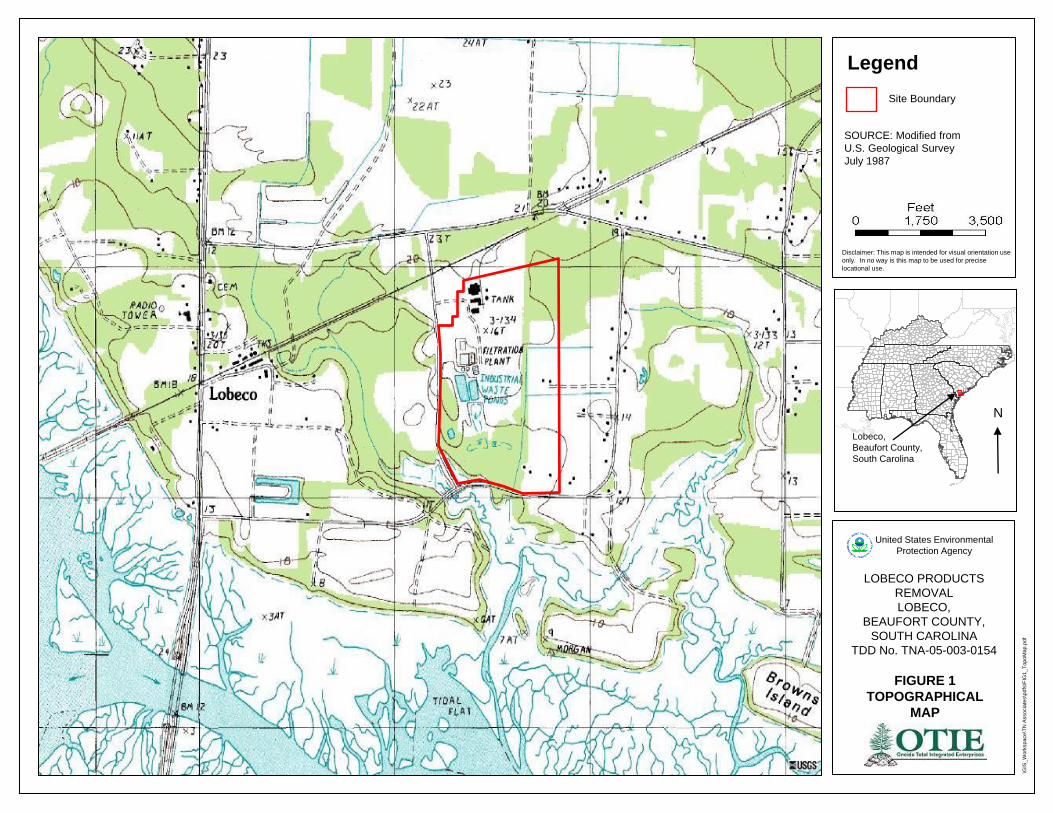
Legend
SOURCE: Modified from
U.S. Geological Survey
July 1987
LOBECO PRODUCTS
REMOVAL
LOBECO,
BEAUFORT COUNTY,
SOUTH CAROLINA
TDD No. TNA-05-003-0154
FIGURE 1
TOPOGRAPHICAL
MAP
\GIS
_W
ork
space
\TN
Associa
tes\p
dfs
\FIG
1_T
opoM
ap.p
df
Disclaimer: This map is intended for visual orientation use
only. In no way is this map to be used for precise
locational use.
Site Boundary
United States Environmental
Protection Agency
Lobeco,
Beaufort County,
South Carolina
N

Legend
SOURCE: Modified from
Google Maps
Image captured January 29, 2011
LOBECO PRODUCTS
REMOVAL
LOBECO,
BEAUFORT COUNTY,
SOUTH CAROLINA
TDD No. TNA-05-003-0154
FIGURE 2
AERIAL MAP
\GIS
_W
ork
space
\TN
Associa
tes\p
dfs
\FIG
1_T
opoM
ap.p
df
Disclaimer: This map is intended for visual orientation use
only. In no way is this map to be used for precise
locational use.
Site Location
United States Environmental
Protection Agency
Lobeco,
Beaufort County,
South Carolina
N

Legend
SOURCE: Beaufort County GIS
2009
LOBECO PRODUCTS
REMOVAL
LOBECO,
BEAUFORT COUNTY,
SOUTH CAROLINA
TDD No. TNA-05-003-0154
FIGURE 3
LOBECO CHEMICAL
PLANT
\GIS
_W
ork
space
\TN
Associa
tes\p
dfs
\FIG
1_T
opoM
ap.p
df
Disclaimer: This map is intended for visual orientation use
only. In no way is this map to be used for precise
locational use.
United States Environmental
Protection Agency
Lobeco,
Beaufort County,
South Carolina
N
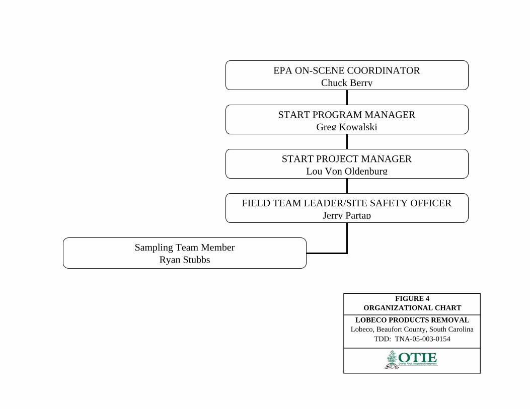
TDD: TNA-05-003-0154
FIGURE 4ORGANIZATIONAL CHART
LOBECO PRODUCTS REMOVALLobeco, Beaufort County, South Carolina
EPA ON-SCENE COORDINATOR Chuck Berry
START PROGRAM MANAGERGreg Kowalski
START PROJECT MANAGERLou Von Oldenburg
FIELD TEAM LEADER/SITE SAFETY OFFICERJerry Partap
Sampling Team MemberRyan Stubbs

APPENDIX B
TABLES
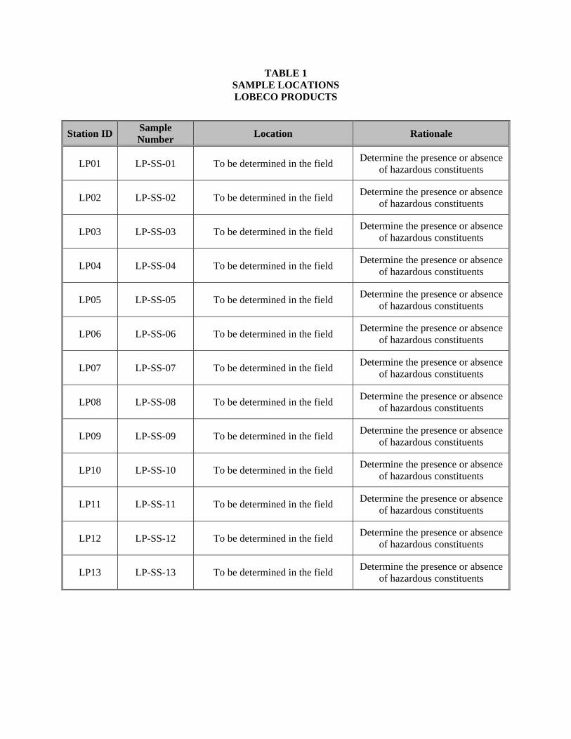
TABLE 1 SAMPLE LOCATIONS LOBECO PRODUCTS
Station ID Sample Number Location Rationale
LP01 LP-SS-01 To be determined in the field Determine the presence or absence of hazardous constituents
LP02 LP-SS-02 To be determined in the field Determine the presence or absence of hazardous constituents
LP03 LP-SS-03 To be determined in the field Determine the presence or absence of hazardous constituents
LP04 LP-SS-04 To be determined in the field Determine the presence or absence of hazardous constituents
LP05 LP-SS-05 To be determined in the field Determine the presence or absence of hazardous constituents
LP06 LP-SS-06 To be determined in the field Determine the presence or absence of hazardous constituents
LP07 LP-SS-07 To be determined in the field Determine the presence or absence of hazardous constituents
LP08 LP-SS-08 To be determined in the field Determine the presence or absence of hazardous constituents
LP09 LP-SS-09 To be determined in the field Determine the presence or absence of hazardous constituents
LP10 LP-SS-10 To be determined in the field Determine the presence or absence of hazardous constituents
LP11 LP-SS-11 To be determined in the field Determine the presence or absence of hazardous constituents
LP12 LP-SS-12 To be determined in the field Determine the presence or absence of hazardous constituents
LP13 LP-SS-13 To be determined in the field Determine the presence or absence of hazardous constituents
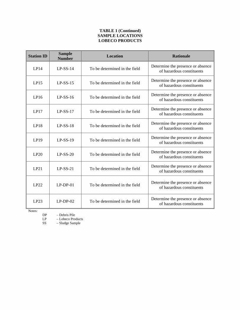
TABLE 1 (Continued) SAMPLE LOCATIONS LOBECO PRODUCTS
Station ID Sample Number Location Rationale
LP14 LP-SS-14 To be determined in the field Determine the presence or absence of hazardous constituents
LP15 LP-SS-15 To be determined in the field Determine the presence or absence of hazardous constituents
LP16 LP-SS-16 To be determined in the field Determine the presence or absence of hazardous constituents
LP17 LP-SS-17 To be determined in the field Determine the presence or absence of hazardous constituents
LP18 LP-SS-18 To be determined in the field Determine the presence or absence of hazardous constituents
LP19 LP-SS-19 To be determined in the field Determine the presence or absence of hazardous constituents
LP20 LP-SS-20 To be determined in the field Determine the presence or absence of hazardous constituents
LP21 LP-SS-21 To be determined in the field Determine the presence or absence of hazardous constituents
LP22 LP-DP-01 To be determined in the field Determine the presence or absence of hazardous constituents
LP23 LP-DP-02 To be determined in the field Determine the presence or absence of hazardous constituents
Notes: DP – Debris Pile
LP – Lobeco Products SS – Sludge Sample

TABLE 2 QUALITY ASSURANCE/QUALITY CONTROL SAMPLES
LOBECO PRODUCTS
Station ID Sample Number Location Rationale
Station ID for parent sample
LP-S-100
Duplicate sludge sample; To be determined in the
field Verify laboratory precision
Station ID for parent sample
LP-S-101
Duplicate sludge sample; To be determined in the
field Verify laboratory precision
Notes: PB – Preservative Blank MB – Metals Blank
BSL – Broadway Street Lead TB – Trip Blank SS – Surface Soil Sample

TABLE 3 ANALYTICAL METHODOLOGY, SAMPLE CONTAINERS, PRESERVATIVES, AND HOLDING TIME FOR SAMPLES
LOBECO PRODUCTS
Matrix Analysis EPA Method Sample Container Preservative Holding Time
Sludge
VOC (TCL) SW846-8260B Three VOA vials; One 2-oz jar
Two vials – NaHSO4 One vial – MeOH
Cool to 4 oC 14 Days
SVOC (TCL) SW846-8270C
One 16-oz jar Cool to 4 oC
14 Days PCBs SW846-8082 14 Days
TAL Metals SW846-6010/7471
28 days Hg; 180 days
others
Pesticides SW846-8081 14 Days
Sludge
VOC (TCLP) 1311 One 2-oz jar Cool to 4 oC 14 Days
SVOC (TCLP) 1311 One 16-oz jar Cool to 4 oC 14 Days
Metals (TCLP) 1311 One 16-oz jar Cool to 4 oC 180 Days
Notes: oC - Degree Celsius SVOC - Semivolatile Organic Compounds PCBs - Polychlorinated Biphenyls oz - Ounce TCL - Target Compound List TCLP - Toxicity Characteristic Leaching Procedure VOC - Volatile Organic Compounds TAL - Target Analyte List
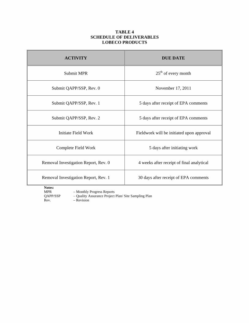
TABLE 4 SCHEDULE OF DELIVERABLES
LOBECO PRODUCTS
ACTIVITY DUE DATE
Submit MPR 25th of every month
Submit QAPP/SSP, Rev. 0 November 17, 2011
Submit QAPP/SSP, Rev. 1 5 days after receipt of EPA comments
Submit QAPP/SSP, Rev. 2 5 days after receipt of EPA comments
Initiate Field Work Fieldwork will be initiated upon approval
Complete Field Work 5 days after initiating work
Removal Investigation Report, Rev. 0 4 weeks after receipt of final analytical
Removal Investigation Report, Rev. 1 30 days after receipt of EPA comments
Notes: MPR – Monthly Progress Reports QAPP/SSP – Quality Assurance Project Plan/ Site Sampling Plan Rev. – Revision


![Quality Assurance Project Plan - University of Kentucky54] Water Distribution System Sampling QAPP...Quality Assurance Project Plan i ... SOP- Standard Operating Procedure SPADNS-](https://img.pdfslide.net/doc/110x75/5aa03bcc7f8b9a71178dc255/pdfquality-assurance-project-plan-university-of-54-water-distribution-system.jpg)