Embed Size (px)
Citation preview

1940Hardinge
manufactures and introduces the 5C
"threaded-nose" spindle
1960'sHardinge
manufactures 5C manual indexers using Hardinge's threaded-nose spindle & collet closer design
2004Hardinge
manufactures 5C Rotary Systems based on
1960's mechanical design
THE EVOLUTION OF THE HARDINGE 5C2 INDEXER SYSTEM
1940'sHardinge
manufactures a 5C dividing head
1901Hardinge
manufactures the 5C Collet
1. HOUSINGMachined and bored on a Dixi 280 precision CNC jig boring machine for close tolerance finish dimensions. Foundry castings (made in the USA) provide vibration damping.
2. SPINDLESpindle is finish ground on a high-precision Kellenberger® CNC universal grinding machine. All surfaces where bearings and gears are installed are ground in the same setup for maximum accuracy.
3. BEARINGSHigh-load, tapered dual roller bearings are used to support heavy radial and axial loads and to provide a longer spindle life.
Hardinge next-generation 5C2 mechanically outmaneuvers the competition.
Curved front casting and removable handle for increased spindle clearance and better tool access.
±5 arc-sec Repeatability±30 arc-sec Accuracy.0002" Max. Runout (.005mm TIR)
Robust, dual-bearing spindle for heavier radial and axial loads. 50-lb (23kg) part weight and 1000-lb (4448N) tailstock thrust per spindle is not a problem – even on a quad unit with tailstocks!
4. DOUBLE ECCENTRICSDouble eccentrics (not single) provide the finest gear mesh adjustment. Hardinge has lowered the backlash range and improved accuracy overall. Customers can perform future gear wear compensation for extended life and improved accuracy over time.
5. WORM DRIVE SHAFTHardened and ground steel worm drive shaft is standard. The process begins on a Hardinge SUPER-PRECISION® CNC lathe and the threads are finish ground on a Drake thread grinder. Grind quality of AGMA class 13 is verified on a Wenzel CNC gear inspection machine.
INSPECTIONFinal inspection of every unit is performed using a Heidenhain encoder mounted directly on the spindle nose to assure final positioning accuracy and repeatability. Printout of accuracy is shipped with each unit.
2
35
6
4
4
1
6. ALUMINUM BRONZE WORMGEAR A high quality worm gear system with 60:1 gear ratioallows for an efficient forward driving capabilitywhile at the same time preventing backdriving fromoccurring. The process begins on a Hardinge SUPER-PRECISION® CNC lathe, then hobbed on a Koepferhobber.
SEALINGHardinge has an extremely thorough seal system to keep coolant out.
MULTIPLE PART SETUPSChoose from dual, triple and quad units for processing multiple parts to increase output. All spindles are synchronized for aligned part orientation within .0002" (.005mm).
Hardinge's GD5C2 has higher accuracy, more spindle clearance and more thrust and radial load.
All rotary products are manufactured in Elmira, New York to strict specifications.
Quality Manufacturing Processes
2004Hardinge
manufactures 5C Rotary Systems based on
1960's mechanical design
2007Hardinge
manufactures and introduces the next-generation 5C2 Rotary System
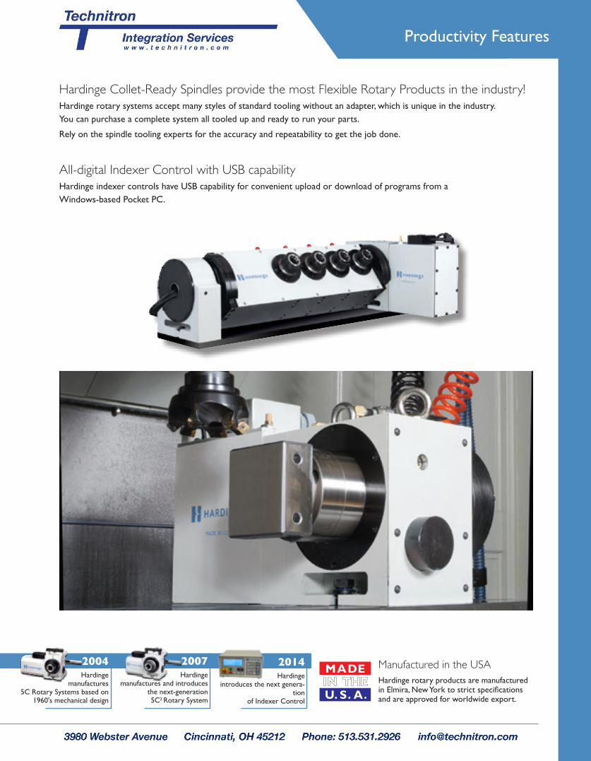
Hardinge Collet-Ready Spindles provide the most Flexible Rotary Products in the industry!Hardinge rotary systems accept many styles of standard tooling without an adapter, which is unique in the industry. You can purchase a complete system all tooled up and ready to run your parts.
Rely on the spindle tooling experts for the accuracy and repeatability to get the job done.
All-digital Indexer Control with USB capabilityHardinge indexer controls have USB capability for convenient upload or download of programs from a Windows-based Pocket PC.
Manufactured in the USAHardinge rotary products are manufactured in Elmira, New York to strict specifications and are approved for worldwide export.
Productivity Features
2014Hardinge
introduces the next genera-tion
of Indexer Control

GD160LP Rotary
and GD210LP Rotary.
Spiral milling
application on
a Bridgeport
knee mill using a
5C2 indexer and
manual tailstock.
Fourth-Axis Integration
GD160LP
Rotary mounted
in a Bridgeport®
vertical machining
center machining
six sides
of the part.
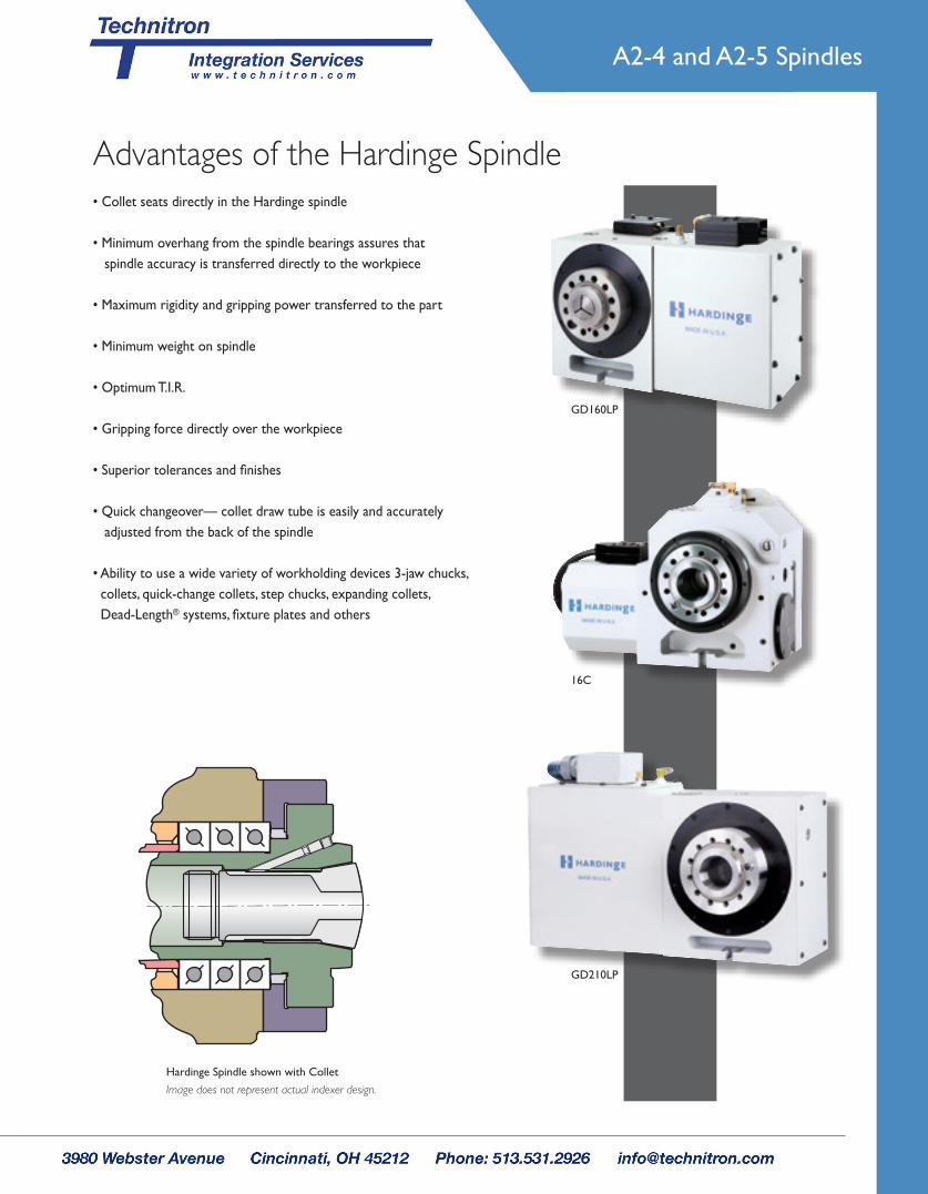
A2-4 and A2-5 Spindles
Advantages of the Hardinge Spindle• Collet seats directly in the Hardinge spindle
• Minimum overhang from the spindle bearings assures thatspindle accuracy is transferred directly to the workpiece
• Maximum rigidity and gripping power transferred to the part
• Minimum weight on spindle
• Optimum T.I.R.
• Gripping force directly over the workpiece
• Superior tolerances and finishes
• Quick changeover— collet draw tube is easily and accuratelyadjusted from the back of the spindle
• Ability to use a wide variety of workholding devices 3-jaw chucks, collets, quick-change collets, step chucks, expanding collets, Dead-Length® systems, fixture plates and others
Hardinge Spindle shown with Collet
Image does not represent actual indexer design.
GD160LP
16C
GD210LP

Disadvantages of other Rotary Spindle Designs
Excessive overhangfrom spindle bearings
Collet
Bar runout
Collet adapter
Minimal distance fromspindle bearings to tool tip
Collet
Grip on bar stock
Other spindle designs require the use of a collet adapter creating an extreme overhang from the spindle bearings.
Any error in the spindle is multiplied by the overhang distance.
This spindle design:• Is not rigid• Is not easily adjusted• Creates poor T.I.R.• Reduces the work envelope• Creates excessive overhang• Does not allow quick changeover
Hardinge Spindle Design – no collet adapter required
Other Rotary Spindle Design – collet adapter required
Image does not represent actual indexer design.
Image does not represent actual indexer design.