Embed Size (px)
Citation preview

Please read and save these instructions. Read carefully before attempting to assemble, install, operate or main-
tain the product described. Protect yourself and others by observing all safety information. Failure to comply
with instructions could result in personal injury and/or property damage! Retain instructions for future refer-
ence.
OPERATING INSTRUCTIONS RC23 & RC30 TRAILER WINCHES
®
Quality Winches Since 1956
General Safety InformationThroughout this manual potential safety hazards will be noted with the following terms. Please read and
understand these terms before operating the product.
Danger means a hazard that
will cause death or serious in-
jury if the warning is ignored.
Caution means a hazard that
may cause minor or moderate
injury if the warning is ignored.
It also may mean a hazard that
will only cause damage to prop-
erty
Warning means a hazard that
could cause death or serious
injury if the warning is ignored.
DescriptionTrailer winches are used for launching and loading boats. The RC23 and RC30 winches feature power-in/free-
wheel out capabilities. These winches are operated with a wireless remote key fob and come equipped with a
12-volt spotlight.
UnpackingWhen unpacking, inspect carefully for any damage that may have occurred during transit. Make sure any loose
fi ttings, bolts, etc.., are tightened before putting unit into service.
P5593100AV 9/04© 2004 Powerwinch
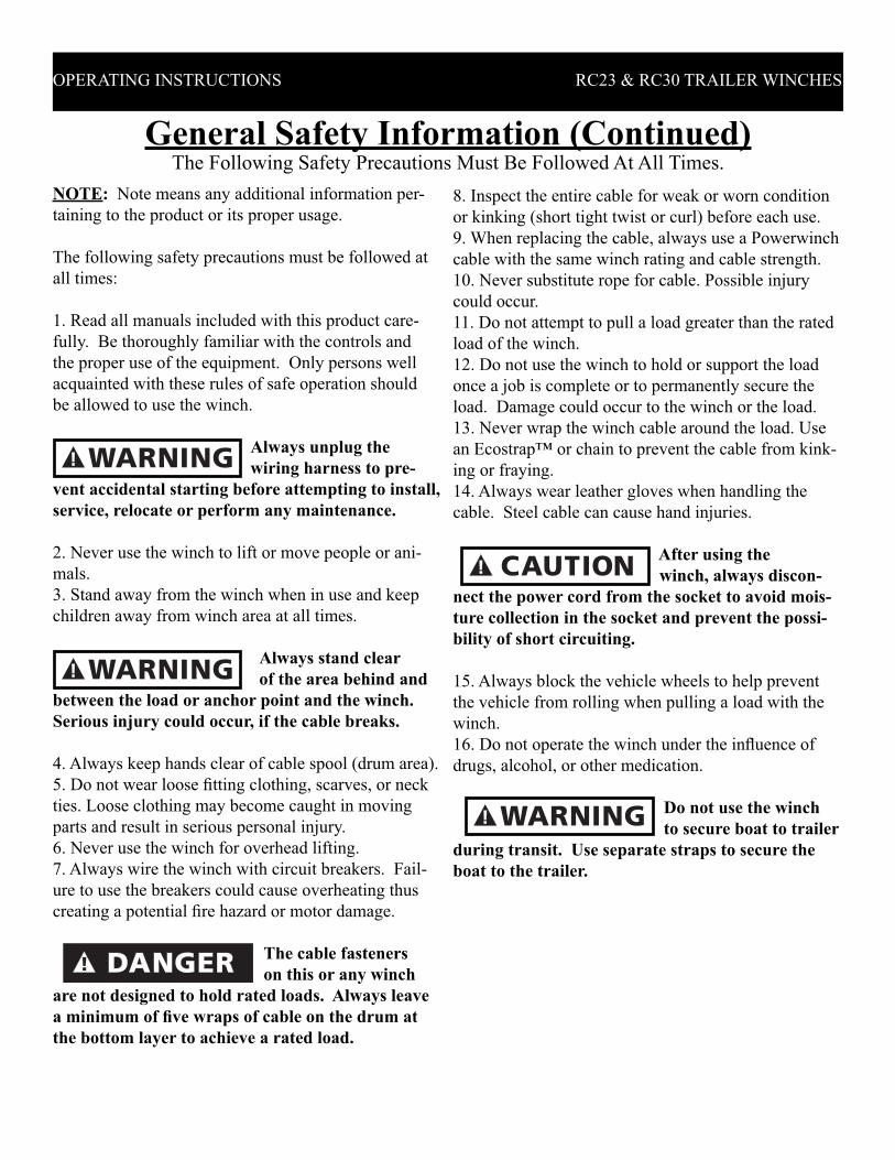
NOTE: Note means any additional information per-
taining to the product or its proper usage.
The following safety precautions must be followed at
all times:
1. Read all manuals included with this product care-
fully. Be thoroughly familiar with the controls and
the proper use of the equipment. Only persons well
acquainted with these rules of safe operation should
be allowed to use the winch.
Always unplug the
wiring harness to pre-
vent accidental starting before attempting to install,
service, relocate or perform any maintenance.
2. Never use the winch to lift or move people or ani-
mals.
3. Stand away from the winch when in use and keep
children away from winch area at all times.
Always stand clear
of the area behind and
between the load or anchor point and the winch.
Serious injury could occur, if the cable breaks.
4. Always keep hands clear of cable spool (drum area).
5. Do not wear loose fi tting clothing, scarves, or neck
ties. Loose clothing may become caught in moving
parts and result in serious personal injury.
6. Never use the winch for overhead lifting.
7. Always wire the winch with circuit breakers. Fail-
ure to use the breakers could cause overheating thus
creating a potential fi re hazard or motor damage.
The cable fasteners
on this or any winch
are not designed to hold rated loads. Always leave
a minimum of fi ve wraps of cable on the drum at
the bottom layer to achieve a rated load.
8. Inspect the entire cable for weak or worn condition
or kinking (short tight twist or curl) before each use.
9. When replacing the cable, always use a Powerwinch
cable with the same winch rating and cable strength.
10. Never substitute rope for cable. Possible injury
could occur.
11. Do not attempt to pull a load greater than the rated
load of the winch.
12. Do not use the winch to hold or support the load
once a job is complete or to permanently secure the
load. Damage could occur to the winch or the load.
13. Never wrap the winch cable around the load. Use
an Ecostrap™ or chain to prevent the cable from kink-
ing or fraying.
14. Always wear leather gloves when handling the
cable. Steel cable can cause hand injuries.
After using the
winch, always discon-
nect the power cord from the socket to avoid mois-
ture collection in the socket and prevent the possi-
bility of short circuiting.
15. Always block the vehicle wheels to help prevent
the vehicle from rolling when pulling a load with the
winch.
16. Do not operate the winch under the infl uence of
drugs, alcohol, or other medication.
Do not use the winch
to secure boat to trailer
during transit. Use separate straps to secure the
boat to the trailer.
General Safety Information (Continued)The Following Safety Precautions Must Be Followed At All Times.
OPERATING INSTRUCTIONS RC23 & RC30 TRAILER WINCHES

% incline
° incline
Level Surface
0°
5%
3°
10%
6°
20%
11°
30%
17°
50%
26°
70%
35°
100%
45°
RC23 24,000 13,340 10,040 6,800 5,220 3,720 3,060 2,580
RC30 40,000 23,345 17,570 11,900 9,135 6,510 5,355 4,515
• A 10% incline (or 6°) is 1 foot rise in 10 ft.
• To convert from pounds (lbs) to kilos (kgs) divide by 2.2.
• Capacity can be increased (almost doubled) by using a pulley block.
Chart 1 - Approximate Rolling Load Capacities (Values are in pounds)
Specifi cationsVarious load conditions will affect winch performance. The line pull required for a specifi c application depends
on the weight of the load, condition of the trailer rollers, and the degree of the loading ramp incline. The chart
below is based on a single line pull and is a guideline to aid in calculating pulling requirements.
NOTE: The noise level of this winch in operation is below 98db (A).
OPERATING INSTRUCTIONS RC23 & RC30 TRAILER WINCHES
Chart 2 - Winch and Boat Capacities
Model Vertical Lift
Capacity
Double Line
Pull
Approximate*
Boat Weight
Approximate*
Boat Size
RC23 2,400 LBS 4,300 LBS 7,500 LBS 17-23 FT
RC30 4,000 LBS 7,500 LBS 11,500 LBS 23-30 FT
* Boat size and weight is approximate and varies depending on boat type. When calculating boat weight be sure
to use fully loaded weight - including boat, motor, fuel, water, gear etc.
Chart 3 - Winch Specifi cations
Model Line Speed
@ Capacity
(FPM)
Gear
Ratio
Voltage
(Volts)
Circuit
Breaker
(Amps)
Unit
Weight
(LBS)
Depth
(Inch)
Height
(Inch)
Width
(Inch)
RC23 14 225:1 12 60 34 9.5 9.0 11.5
RC30 8 450:1 12 60 36 9.5 9.0 11.5
OPERATING INSTRUCTIONS RC23 & RC30 TRAILER WINCHES
Winch InstallationMOUNTING
The winch can be mounted on the trailer in the same
position and location as an existing hand winch. Af-
ter removing the hand winch, bolt the Powerwinch
unit using a minimum of (2) 3/8” Grade 5 machine
bolts and lock nuts (for easier mounting the Power-
winch Quick Mount Kit (P7700000AJ) is available
from the dealer).
The cable hook on the winch and the bow eye on the
boat should be at the same height when the boat is
in the fully loaded position on the trailer. If the bow
eye is too high, extra pull is required of the winch
and extra stress is exerted on the boat’s stern and
bow eye.
To achieve equal height of the winch and boat, raise
or lower the winch stand. In most cases, the trailer
manufacturer will have an adapter available for use
with a winch.
Be sure that the winch antenna is vertical and
unobstructed from trailer frame.
A minimum of 12
inch clearance is
required between the winch and the bow eye to
prevent the cable hook from being drawn into the
winch drum when the boat is in the fully loaded
position on the trailer. If necessary, extend the
bow stop to obtain the clearance.
When using a double line pull (using a pulley
block), install an appropriate eye bolt on the winch
stand as close as possible to the base of the winch.
If a Quick Mount Kit is used, make sure the winch
is in the forward position before installing the eye
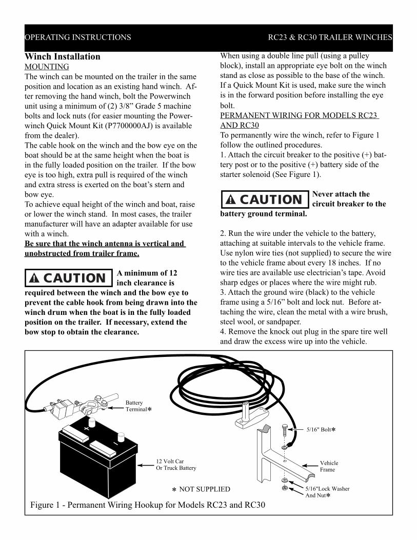
bolt. PERMANENT WIRING FOR MODELS RC23
AND RC30
To permanently wire the winch, refer to Figure 1
follow the outlined procedures.
1. Attach the circuit breaker to the positive (+) bat-
tery post or to the positive (+) battery side of the
starter solenoid (See Figure 1).
Never attach the
circuit breaker to the
battery ground terminal.
2. Run the wire under the vehicle to the battery,
attaching at suitable intervals to the vehicle frame.
Use nylon wire ties (not supplied) to secure the wire
to the vehicle frame about every 18 inches. If no
wire ties are available use electrician’s tape. Avoid
sharp edges or places where the wire might rub.
3. Attach the ground wire (black) to the vehicle
frame using a 5/16” bolt and lock nut. Before at-
taching the wire, clean the metal with a wire brush,
steel wool, or sandpaper.
4. Remove the knock out plug in the spare tire well
and draw the excess wire up into the vehicle.
BatteryTerminal*
5/16" Bolt*
5/16"Lock WasherAnd Nut*
12 Volt CarOr Truck Battery
VehicleFrame
* NOT SUPPLIED
Figure 1 - Permanent Wiring Hookup for Models RC23 and RC30
TEMPORARY WIRING FOR MODELS RC23
AND RC30
To temporary wire the winch, follow the outlined
procedures. A quick connect wiring harness is avail-
able from the dealer (Part Number P7866000AJ)
for Models 712A and 912. Order part number
P7865900AJ for Model 315.
1. Attach two large “alligator” type clips, one to the
circuit breaker and one to the end of the black wire.
2. Run the red wire (with the circuit breaker) to the
battery and clip the wire to the hot (positive) side of
the battery.
3. Clip the black wire to the vehicle frame or nega-
tive side of the battery.
Transmitter Instructions
The Powerwinch RC30 and RC23 winches are
equipped to operate with a radio frequency trans-
mitter and receiver module. Every transmitter and
receiver module are pre-programmed at the factory
to communicate with each other. Please refer to
the following instructions for a description of the
transmitter functions. In the event that the trans-
mitter is destroyed or lost a new transmitter can be
programed by following the instructions outlined in
the section titled “Programming a replaced Trans-
mitter”
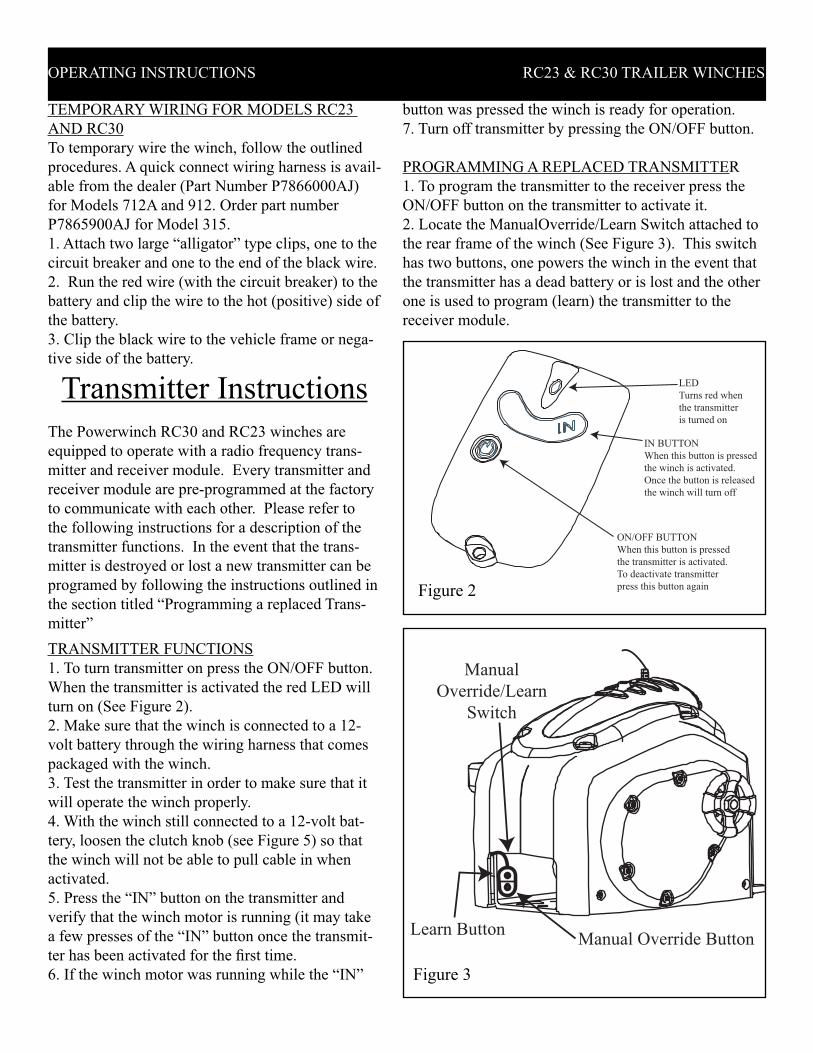
TRANSMITTER FUNCTIONS
1. To turn transmitter on press the ON/OFF button.
When the transmitter is activated the red LED will
turn on (See Figure 2).
2. Make sure that the winch is connected to a 12-
volt battery through the wiring harness that comes
packaged with the winch.
3. Test the transmitter in order to make sure that it
will operate the winch properly.
4. With the winch still connected to a 12-volt bat-
tery, loosen the clutch knob (see Figure 5) so that
the winch will not be able to pull cable in when
activated.
5. Press the “IN” button on the transmitter and
verify that the winch motor is running (it may take
a few presses of the “IN” button once the transmit-
ter has been activated for the fi rst time.
6. If the winch motor was running while the “IN”
LED
Turns red when
the transmitter
is turned on
IN BUTTON
When this button is pressed
the winch is activated.
Once the button is released
the winch will turn off
ON/OFF BUTTON
When this button is pressed
the transmitter is activated.
To deactivate transmitter
press this button againFigure 2
Manual Override Button
Manual
Override/Learn
Switch
Learn Button
Figure 3
OPERATING INSTRUCTIONS RC23 & RC30 TRAILER WINCHES
button was pressed the winch is ready for operation.
7. Turn off transmitter by pressing the ON/OFF button.
PROGRAMMING A REPLACED TRANSMITTER
1. To program the transmitter to the receiver press the
ON/OFF button on the transmitter to activate it.
2. Locate the ManualOverride/Learn Switch attached to
the rear frame of the winch (See Figure 3). This switch
has two buttons, one powers the winch in the event that
the transmitter has a dead battery or is lost and the other
one is used to program (learn) the transmitter to the
receiver module.

OPERATING INSTRUCTIONS RC23 & RC30 TRAILER WINCHES
RECOMMENDED OPERATING PROCEDURES
1. Always be sure that the transmitter is operating
above or at the same level as the winch (see Figure
4). If the transmitter is operating below the surface
of the winch the winch may experience periods of
interrupted power.
2. When operating the winch be sure to point the
transmitter straight up and with the “Hot Edge” of the
transmitter facing the winch (see Figure 4).
3. The transmitter performs best when it is within a
10-15 foot radius of the winch. Depending on the op-
erating environment if is very possible for the trans-
mitter to preform well within a 30-40 foot radius.
4. The receiver module receives a stronger signal
from the transmitter when the transmitter is operated
on one of the two sides of the winch. There exists a
greater chance of a “drop out” when the transmitter is
used in front of or behind the winch.
6. A “drop out” is when the signal is interrupted
between the transmitter and the receiver causing the
winch to stop running. If this event occurs simply re-
lease the “IN” button and press it again and the winch
should resume running.
Figure 4
5. If a great number of “drop outs” are occurring, the
battery in the transmitter may need to be changed.
Generally, when the battery voltage of the transmitter
drops below 9-volts the range and performance of the
transmitter will decrease.
BATTERY REPLACEMENT
1. Remove the screw located on the back side of the
transmitter.
2. Separate the two halves of the transmitter and re-
move the silicon gasket off of the printed circuit board.
3. Remove the old battery and replace it with a new
one. The polarity is very important, make sure to
place the battery between the tabs so that the polar-
ity matches what is indicated on board.
IMPORTANT
*Use extreme caution when using this system.
**The transmitter is an electronic device so keep as
dry as possible.
***The transmitter must be turned off after every
use. The battery in the transmitter will be drained
of power if the transmitter is left on. The trans-
mitter will only accept a size A23 battery, which is
commonly available at stores. This battery must be
replaced once every three months or twice during a
boating season to ensure the highest preformance.
****In the event that the transmitter is lost or bro-
ken another one can be obtained from Powerwinch.
The transmitter can be removed from the receiver
by pressing and holding the learn button for twenty
fi ve seconds while the winch is connected to 12-volt
power. Once the new transmitter is obtained it will
have to be programmed to the receiver as explained
earlier.
10-15 FEET
OPERATING RADIUS FOR BEST RESULTS THE
TRANSMITTER SHOULD BE
POINTING UP WITH THE "HOT
EDGE" OF THE TRANSMITTER
FACING THE WINCH WHILE
OPERATING. THE TRANSMITTER
SHOULD ALSO BE HIGHER THAN
THE WINCH
HOT EDGE OF TRANSMITTER
3. The button closest to the wires is the learn button.
4. Press and hold the learn button at the rear of the
winch frame for two seconds and then release the
button.
5. Now, press the button marked “IN” on the trans-
mitter and hold for one second and then release it.
6. Press the “IN” button one more time and hold for
one second again.
7. The transmitter should now be programmed to the
winch. Test the transmitter as described earlier.

OPERATING INSTRUCTIONS RC23 & RC30 TRAILER WINCHES
Figure 5
1. Attach the winch cable hook to the bow eye on the
boat.
Always stand clear
of the area behind and
between the load or anchor point and the winch.
Serious injury could occur if the cable breaks.
The clutch control knob on the side of the winch con-
trols the loading and unloading operation (See Figure
5). Turning the knob counterclockwise releases the
brake and allows the cable to free-wheel out.
2. Turn the clutch knob slowly in a counterclockwise
motion to release the brake on the winch.
3. Allow the boat to slide off the trailer (a slight push
may be necessary to start the boat down the trailer).
If needed, turn the clutch knob counterclockwise to
use the brake to slow the boat at launch.
4. When the boat is in the water, release the winch
cable hook from the bow eye. Be sure to keep con-
stant pressure on the cable when rewinding the cable
with no load. A loose cable may rewind improperly
and damage the levelwind plate. Secure the cable
hook to prevent personal injury or property damage.
ClutchControl Knob
Winch CableHookTurn
COUNTER-CLOCKWISE
To ReleaseBrake
The Transmitter and receiver devices used in the
RC23 and RC30 comply with the FCC Part 15. Op-
eration is subject to the following two conditions:
I. This device may not cause harmful interference.
II. This device must accept any interference received,
including interference that may cause undesired op-
eration.
Section 15.105 Information to the user
Note: This equipment has been tested and found to
comply with the limits for a Class B digital device,
pursuant to Part 15 of the FCC Rules. These limits are
designed to provide reasonable protection against
harmful interference in a residential installation. This
equipment generates, uses and can radiate radio
frequency energy and, if not installed and used in
accordance with the instructions, may cause harmful
interference to radio communications. However, there
is no guarantee that interference will not occur in a
particular installation. If this equipment does cause
harmful interference to radio or television reception,
which can be determined by turning the equipment off
and on, the user is encouraged to try to correct the
interference by one or more of the following
measures:
__Reorient or relocate the receiving antenna.
-- Increase the separation between the equipment and
receiver.
-- Connect the equipment into an outlet on a circuit
different from that to which the receiver is connected.
-- Consult the dealer or an experienced radio/TV
technician for help.
-- Caution any changes or modifi cations not expressly
approved by Powerwinch voids user’s authority to
operate this equipment.
Winch OperationUNLOADING
To unload the boat, and follow the outlined proce-
dures.
Clear the area around
and behind the boat
of people, animals, and obstructing objects before
loading or unloading or personal injury could oc-
cur.
LOADING
1. Align the boat and trailer make sure that the antenna
is vertical and unobstructed by the trailer frame.
Always stand clear
of the area between the
load or anchor point and the winch. Serious injury
could occur if the cable breaks.
2. Free-wheel the winch cable out and attach the cable
hook to the eye on the boat.
3. Turn the clutch control knob clockwise until fi nger
tight to set the brake (See Figure 6).
EMERGENCY HAND CRANK
The emergency hand crank is included with models
4. Remove the outer nut shown in Figure 8 and place
the emergency hand crank on the shaft.
5. Tighten the outer nut fi rmly against the hand
crank.
6. Turn crank handle counter clockwise on the RC23
and clockwise on the RC30 to retreive boat.
After using the emergency hand crank, follow the
procedures outlined below.
1. Remove the outer nut shown in Figure 8 and re-
move the emergency hand crank off the shaft.
2. Tighten the outer nut fi rmly against the inner nut.
3. Replace emergency crank handle as shown in
Figure 7. Make sure that the handle is secure before
traveling.
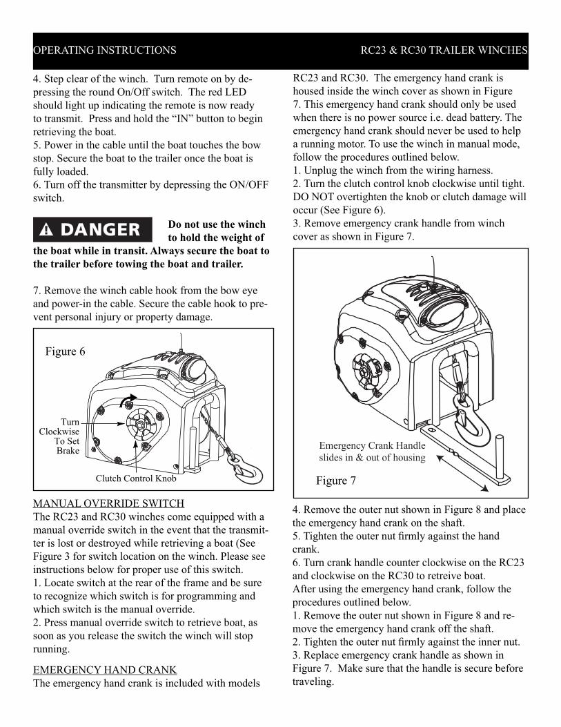
Emergency Crank Handle
slides in & out of housing
Figure 7
OPERATING INSTRUCTIONS RC23 & RC30 TRAILER WINCHES
4. Step clear of the winch. Turn remote on by de-
pressing the round On/Off switch. The red LED
should light up indicating the remote is now ready
to transmit. Press and hold the “IN” button to begin
retrieving the boat.
5. Power in the cable until the boat touches the bow
stop. Secure the boat to the trailer once the boat is
fully loaded.
6. Turn off the transmitter by depressing the ON/OFF
switch.
Do not use the winch
to hold the weight of
the boat while in transit. Always secure the boat to
the trailer before towing the boat and trailer.
7. Remove the winch cable hook from the bow eye
and power-in the cable. Secure the cable hook to pre-
vent personal injury or property damage.
Figure 6
Clutch Control Knob
TurnClockwise
To SetBrake
RC23 and RC30. The emergency hand crank is
housed inside the winch cover as shown in Figure
7. This emergency hand crank should only be used
when there is no power source i.e. dead battery. The
emergency hand crank should never be used to help
a running motor. To use the winch in manual mode,
follow the procedures outlined below.
1. Unplug the winch from the wiring harness.
2. Turn the clutch control knob clockwise until tight.
DO NOT overtighten the knob or clutch damage will
occur (See Figure 6).
3. Remove emergency crank handle from winch
cover as shown in Figure 7.
MANUAL OVERRIDE SWITCH
The RC23 and RC30 winches come equipped with a
manual override switch in the event that the transmit-
ter is lost or destroyed while retrieving a boat (See
Figure 3 for switch location on the winch. Please see
instructions below for proper use of this switch.
1. Locate switch at the rear of the frame and be sure
to recognize which switch is for programming and
which switch is the manual override.
2. Press manual override switch to retrieve boat, as
soon as you release the switch the winch will stop
running.

OPERATING INSTRUCTIONS RC23 & RC30 TRAILER WINCHES
MaintenanceLUBRICATION
The cable should be lubricated a minimum of once a
year with Whitmore’s Wire Rope Spray, WD40 or a
similar product. Spray the shaft and the cable as the
cable is being wound. Remove the cover and lubricate
the gears a minimum of once a year with a lithium base
grease. Be careful not to get grease on the clutch lining.
CABLE REPLACEMENT
Always unplug the
wiring harness to pre-
vent accidental starting before attempting to install,
service, relocate or perform any maintenance.
To replace the cable, follow the outlined procedures.
Use an exact replacement Powerwinch cable. The
winch rating and cable strength are carefully matched.
Never replace the cable with rope.
1. Unplug the wiring harness. Loosen
the clutch knob and free-wheel the cable out.
2. It is not necessary to remove the cover in order to
replace the cable, however, removing the cover does
create more access to the drum shaft and make the
installation more easy.
3. Cut the old cable approximately 2” from the drum
and push the remaining cable and fastener through the
drum to remove (See Figure 9).
4. Insert the new cable into the drum shaft hole at the
end opposite the counterbored end. Draw the cable
through the hole and out the counterbored side of the
shaft.
Figure 8
Emergency Crank Handle
Spare
1/2"-20
Lock Nut
5. Push the cable through the fastener until the cable
end is fl ush with the end of the fastener.
6. Crimp the fastener onto the cable and pull the
cable through the drum shaft until the fastener seats
inside the counterbore.
7. Reassemble the cover halves back onto the winch
if they were removed during the cable installation
process.
8. Power-in the cable with a light load to help wind
the cable straight into the drum.
LEVELWIND PLATE
1. When powering-in the cable, the motor will con-
tinue to run for a few seconds after releasing the
switch, especially without a load. Be sure to allow
for the extra cable when powering-in. Do not let the
cable hook go into the winch and bend the level wind
plate.
LIGHT OPERATION
The RC23 and RC30 winches come equipped with a
12-volt light source. The light can be used when the
winch is running or when it is idle, the winch must
be wired to a 12-volt battery in order for the light to
function. There is a push button switch located at the
top of the winch behind the antenna that activates the
light. Push the button once to turn the light on and
push it again to turn it off (See Figure 10 for operat-
ing instructions).
CableFastener
Counterbore
Cable Drum
InsertNew Cable
2"
Figure 9
OPERATING INSTRUCTIONS RC23 & RC30 TRAILER WINCHES
P55919
SCREW
(2X)
P55909
LENS
P55932
GASKET
P55908
LIGHT BULB
LIGHT SWITCH
PUSH ON/OFF
Figure 10
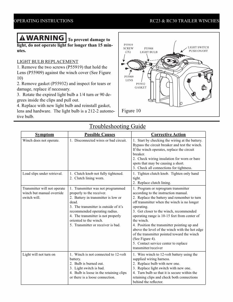
To prevent damage to
light, do not operate light for longer than 15 min-
utes.
LIGHT BULB REPLACEMENT
1. Remove the two screws (P55919) that hold the
Lens (P55909) against the winch cover (See Figure
10)
2. Remove gasket (P55932) and inspect for tears or
damage, replace if necessary.
3. Rotate the expired light bulb a 1/4 turn or 90 de-
grees inside the clips and pull out.
4. Replace with new light bulb and reinstall gasket,
lens and hardware. The light bulb is a 212-2 automo-
tive bulb.
Symptom Possible Causes Corrective Action
Winch does not operate. 1. Disconnected wires or bad circuit. 1. Start by checking the wiring at the battery.
Bypass the circuit breaker and test the winch.
If the winch operates, replace the circuit
breaker.
2. Check wiring insulation for worn or bare
spots that may be causing a short.
3. Check all connections for tightness.
Load slips under retrieval. 1. Clutch knob not fully tightened.
2. Clutch lining worn.
1. Tighten clutch knob. Tighten only hand
tight.
2. Replace clutch lining.
Transmitter will not operate
winch but manual override
switch will.
1. Transmitter was not programmed
properly to the receiver.
2. Battery in transmitter is low or
dead.
3. The transmitter is outside of it’s
recommended operating radius.
4. The transmitter is not properly
oriented to the winch.
5. Transmitter or receiver is bad.
1. Program or reprogram transmitter
according to the instruction manual.
2. Replace the battery and remember to turn
off transmitter when the winch is no longer
operating.
3. Get closer to the winch, recommended
operating range is 10-15 feet from center of
the winch.
4. Position the transmitter pointing up and
above the level of the winch with the hot edge
of the transmitter pointed toward the winch
(See Figure 4).
5. Contact service center to replace
transmitter/receiver
Light will not turn on 1. Winch is not connected to 12-volt
battery.
2. Bulb is burned out.
3. Light switch is bad.
4. Bulb is loose in the retaining clips
or there is a loose connection.
1. Wire winch to 12-volt battery using the
supplied wiring harness.
2. Replace bulb with new one.
3. Replace light switch with new one.
4. Turn bulb so that it is secure within the
retaining clips and check both connections
behind the refl ector.
Troubleshooting Guide

OPERATING INSTRUCTIONS RC23 & RC30 TRAILER WINCHES
Technical InformationFor information on the operation or repair, please call
AU: 1800-059-899 or NZ: 0800-876-526.
Replacement Parts InformationFor information regarding where to order replacement parts, call the above numbers. Please have the following information available:
Winch Model Number
Winch Serial Number
Part Number and Description
Address correspondence to:
Limited WarrantyA. This Limited Warranty is given by the Pow moC rezteF ttocS eht fo nois iv iD hcniw re giro eht ot )”yn ap moC“ eht( yn ap eht( resahcrup lan i
nam siht ni deif i ceps )”tcudorP“ eht( tcu dorP hcniw re woP a fo )”resahcruP“ snart ton si yt nar raW detimiL sihT .la u .ytrap rehto yna ot elba refB. Responsibilities of the Company under this Limited Warranty:
1. Re pair or replace (at the discretion of the Com dorP eht fo strap ro trap yna )yn ap uct found by the Com )2( eno a nihtiw evitcefed eb ot yn apyear period from the date of pur chase.
2. The Company will pay the transportation charge for ship ment back to the Purchaser of any Prod uct re .riap er yt nar raW etamitigel rof deviec:yt nar raW detimiL siht rednu resahcruP eht fo seitilibisnopseR .C
rup fo foorp detad wohs ot evah lliw re sahc ruP .1 chase to qualify for service under the pro .ytnarraW detimiL eht fo snois iv2. Promptly notify the Seller or the Com .rednuereh mialc yna fo yn ap
na ot ro irp nevig eb tsum noit az ir oht uA .noitcepsni rof ynapmoC eht ot tcudorP eht nruter ,ynapmoC eht fo noitpO eht tA .3 er tcu dorP y turn. Call the Company at 1-513-539-7215 or write the Com moc dna noitazirohtua rof ,05054 HO ,eornoM ,eunevA notwaL 103 ta yn ap plete
dorP eht nruter ot woh no snoit curts ni uct di moC eht ot yl tcer .yn ap4. Use reasonable care in maintenance, op ca ni tcudorP eht fo egarots dna esu ,noit a re ni eht htiw ecnad roc noc snoit curts tained in the Own er’s
.la u naM5. Have Warranty work performed by a deal er or rep moC eht yb devorp pa evit at nes er .yn ap
er eht era se grahc noitatropsnart ,.2.B ni deton sa tpecxE .6 spon si bil i ty of the Pur chas er.D. This Limited Warranty covers:
1. Defects in workmanship or materials.2. Any part or parts of the Product sold or man moC eht yb derut caf u .yn ap
E. This Limited Warranty does not cover:1. Any failure that results from improper in .tcudorP eht fo noit al lats2. Any failure that results from accident, Pur niam reporpmi ,noitacifidom ,tcelgen ,esuba s’re sahc liaf ro ,ecnan et ure to operate and use the
Product in ac ni eht htiw ecnad roc struc tions pro vid ed in the Own er’s Man u al sup plied with the Prod uct. raw deilp mI .yt nar raw sserpxe rehto on si erehT .F rem fo esoht gni dulc ni ,seit nar tif dna yt i liba tnahc mil era ,esop rup ral u cit rap a rof ssen ited to one
(1) year from date of pur ni lla dna yna rof ytilibail yna dna yde mer evis ulc xe eht si sihT .esahc se snep xe ro se ga mad lait neuq es noc ro lat ned ic .de dulc xe si re ve os tahw
Some states do not allow lim raw deilpmi na gnol woh no snoit at i lait neuq es noc ro lat ned ic ni fo noitatimil ro nois ulc xe wolla ton od ro ,stsal yt nar mil evoba eht ,se ga mad miL sihT .uoy ot ylppa ton yam snoit at i sthgir rehto evah osla yam uoy dna ,sthgir lagel cificeps uoy sevig ytnarraW de ti
which vary from state to state.
Trail Com AU LimitedUnit 5, 25-27 South LinkDandenong, Melbourne Victoria 3175
Trail Com Limited15 Oaks Road,Manukau, AucklandNew Zealand
or

1
1
13
16
7
6
23
24
2
3
54
8
9
10
12
11
17
1514
27
18
4
26
25
22
21
20
19
28
29
ITEM # RC23 PART # RC30 PART # DESCRIPTION QTY
1 - - WINCH MECHANISM 1
2 P79566 P79566 COVER SCREW 10-32 X .5” 2
3 P55917 P55917 PLASTITE SCREW 8-16 X .25” 11
4 P55919 P55919 PLASTITE SCREW 8-16 X .50” 4
5 P78103 P78103 POWER SOCKET 1
6 P55904 P55904 COVER, POWER SOCKET SIDE 1
7 P55922 P55922 SCREW, SHEET METAL #8 2
8 P55901 P55901 RECEIVER MODULE 1
9 P55907 P55907 MOUNTING BRACKET 1
10 P55914 P55914 REFLECTOR 1
11 P55916 P55916 WASHER #3 2
12 P55915 P55915 HEX NUT #3-48 2
13 P55911 P55905 COVER, TOP 1
14 P55928 P55928 PLASTITE SCREW, 1/4-10 X .75” 4
15 P55932 P55932 GASKET KIT 1
16 P55929 P55929 SWITCH BOOT 1
17 P55938 P55938 GROMMET, ANTENNA 1
18 P55932 P55932 GASKET KIT 1
19 P55912 P55912 BATTERY CLIP 2
20 P55913 P55913 SCREW #3-48 2
21 P55908 P55908 LIGHT BULB 1
22 P55924 P55924 BALL DETENT 1
23 P55903 P55903 COVER, CLUTCH SIDE 1
24 P55947 P55947 EMERGENCY CRANK HANDLE 1
25 P55910 P55910 CLUTCH KNOB 1
26 P55923 P55923 SCREW, 10-32 X 1.5” 2
27 P55909 P55909 LENS 1
28 P55902 P55902 TRANSMITTER KEY FOB 1
29 P55930 P55930 SWITCH, LIGHT 1
R
Model RC23 & RC30Replacement Parts Guide
For Cover Assembly

5
4
2 19
40
391517
1516
15
1413
44
45
41
1520
1521
2223
1325
22
13
24
2530
30
30
2928
35
34
32
43
31
33
3637
38
26
2015
27
7
12
11
10
3
95
5
94
83
1
48
42
6
18
R
Model RC23 & RC30Replacement Parts Guide
For Winch Assembly
ITEM # RC23 PART# RC30 PART # DESCRIPTION RC23 QTY RC30 QTY
1 P70102 P70102 Frame assembly 1 1
2 P71101 P71101 Stud, clutch 1 1
3 P71612 P71612 Thrust, race 2 2
4 P71609 P71609 Bearing 2 2
5 P71613 P71613 Washer, thrust 3 3
6 P71716 P71759 Gear powered assembly 1 1
7 P73602 P73602 Lining,clutch 1 1
8 P71755 P71755 Gear pinion assembly 1 1
9 P79800 P79800 Washer, spring 2 2
11 P78302 P78302 Wiring Harness with Breaker 1 1
12 P10122 P10122 Hex Nut 1 1
13 P79738 P79738 Nut, Tri-loc jam 5 5
14 P71703 P71703 Gear, drive 57 T 1 1
15 P71822 P71822 Washer 6 6
16 P71818 P71818 Spacer, rear shaft 1 1
17 P71607 P71607 Bearing 1 1
18 - P71819 Spacer, rear shaft - 1
19 P71202 P71201 Shaft,rear gear 1 1
20 P71608 P71608 Bearing 1 1
21 - P71817 Spacer, rear shaft - 1
22 P71704 P71704 Gear, pinion 12T 1 2
23 P71818 P71816 Spacer, rear shaft 1 1
24 - P71796 Gear, idler 24T - 1
25 - P71606 Bearing - 1
26 - P71301 Shaft, intermediate - 1
27 - ST070233AV Ring, retaining - 1
11
47
46

ITEM # RC23 PART# RC30 PART # DESCRIPTION RC23 QTY RC30 QTY
28 P79716 P79716 Nut, Tri-loc 1 1
29 P71795 P71795 Gear 1 1
30 P71821 P71821 Washer, spacer 3 3
31 P71960 P71960 Flange, drum 1 1
32 P71401 P71401 Shaft, drum 1 1
33 P71858 P71858 Fastener, cable 1 1
34 P7188800AJ P7188800AJ Cable assembly 1 1
35 P71954 P71954 Flange, drum split 1 1
36 P71820 P71820 Spacer 1 1
37 P71605 P71605 Bearing 1 1
38 P79715 P79715 Nut, hex jam 5/8”-16 1 1
39 P70212 P70205 Plate, levelwind 1 1
40 - ST161702AV Rivet - 2
41 P72117 P72118 Motor assembly 1 1
42 P79543 P79543 Machine Screw #10-32 X 1.00” 1 1
43 P79088 P79088 Drum collar 1 1
44 ST161301AV ST161301AV Band, quick release motor 2 2
45 P78118 P78118 Solenoid 1 1
46 P79403 P79403 Pulley Block Assy 1 1
47 P79020 P79020 Hook 1 1
48 P79701 P79701 #10-32 Lock Nut 1 1