Embed Size (px)
Citation preview
(N- LflMETRIC[
DOD-HDBK-178(ER)
N 25 JULY 1986
MILITARY HANDBOOKI
QUANTITATIVE DESCRIPTION OFOBSCURATION FACTORS FOR
ELECTRO-OPTICAL AND MILLIMETERWAVE SYSTEMS
METRIC
DTIC.S EP 2 4 1986
C ALJ
i:E
DISTRIBUTION STATEMENT A. Approved for public release; distribution is unlimited.
NO DELIVERABLE DATA REQUIREDBY THIS DOCUMENT AREA MISC
DOD-HDBK-178(ER)
DEPARTMENT OF DEFENSE
WASHINGTON, DC 20301
Quantitative Description of Obscuration Factors for Electro-Optical and Millimeter Wave Systems
1. This standardization handbook was developed by the Atmospheric Sciences Laboratory of the USArmy Laboratory Command with the assistance of other organizations within the Department of theArmy and industry.
2. This document supplements departmental manuals, directives, military standards, etc., and pro-vides fundamental information on the effects of natural and battlefield-induced obscurants on electro-optical and millimeter wave systems. It contains tables that list the effects as major or minor, equationsthat allow detailed calculation of effects, and illustrative problems with realistic scenarios. It shouldprovide valuable information to engineers and managers responsible for the design of electro-opticaland millimeter wave systems.
3. Beneficial comments (recommendations, additions, deletions) and any pertinent data that may beof use in improving this document should be addressed to Commander/Director, US Army LaboratoryCommand, Atmospheric Sciences Laboratory, ATTN: SLCAS-AR-A, White Sands Missile Range, NM88002-5501, by uising the self-addressed Standardization Document Improvement Proposal (DD Form1426) appearing at the end of this documentor by letter.
DOD-HDB K-i 78(EH)
FOREWORD
The general Purpose of thlis handlbook is to provide ,1grade sensor performance. Chapter 3 provides quantita-Arydesignl enigineers, scienltists, anid analysts with at tive information onl natural obSCUrants, while Chapter
mlethod to quati fy obsctaration factors for clectro- 'Icon tains quantitative information oil battlefield-
Optical ( EO) and~ millimeter wve (m1mw1%) systems. Thie induced conaminanlts. Chapter 5 describes sensor per-speccific' Pupses are ( I) to provide data and ilethodol- formatce measures, discusses sensor performinw( cfa
ogy for Army design enginieers to aIssess thle ef[ects Of mechanIismIs, an1d illuIstrates sensor perfornianc?.alcu-natural obsctirants and battlefield-i ndtuCd contami- lit ions using thle quan IIti tati'Ve data dCeeoped InI Chap-nanits onl EO and injimi systems, (2) to provide thie ters 3 and 4I.analytical communitkliyN With inlformalitionl to calIculate This handbook wvas developed under thle auspices ofsNystem performance, and (3) to inidicate to thle test andl the Army Materiel Command's Engineerinig Design /evaluation cmmunuity the effects that should hemcnsul- Handbook Program, un1der tile dirctionl of the LIS
erect when aI system is evaluated. Army Managemnent Engineering Trii ng Ac-tivity.
Chapter I i's at discussionl of thle handbook c-ontents The handbook was writ ten by 1)(,S Corporation ats
and the uise- of the hanmdbook. Chapter 2 is a, qumal itat ive sub)COntractor to Research Triangle Inst itu te under
description of E() Zmd 1mm1w sensors and of the niatural IContract No. I)AAAO8.80-C-02,17.obscuran ts and1( bat Ilefield-conta Iin anl ts that mlay de-J
IQUA Lmr
4 D isl vi ~ ))
Avatl';,bil 1tv Codes
Dist Spe C i "II

DOD-HDBK-1 78(ER)
This paoe intentioniy left blank.
iv
DOD-HDBK-178(ER)j
CONTENTS
Paar hLISI'OF ILLUSTRATIONS..........................
LIST OFTABLES ....................................................................................... xiLIST OF ACRONYMS AND ABBREVIATIONS ...................................................... xiiiEXECUTIVE SUMMARY ............................................................................... xiv
CHAPTER 1INTRODUCTION
I-1 PURPOSE..................................-1-2 SCOPE...................................-1-3 DESRIPTrION AND USE OF THE HANDBOOK.....................................................-
CHAPTER 2QUALITATIVE DESCRIPTION OF SENSORS
AND OBSCURATION FACTORS
2-0 LIST OF SYMBOLS ........................................................................................ 2-12-1 INTRODUG(TION ...................................................................................... 2-22-2 ELEC TRO-OPTICAL. AND MILLIMETER WAVE SENSORS ................................... 2-22-2.1 VISIBLE AND NEAR IR SENSORS (0,'1-2.0 pmn)........................................... ....... 2-12-2.2 THERMAL SYSTEMS (3-5 and 8.12jum) ........................................................... 2-42-2.3 MILLIMETER WAVE SENSORS (35 and 94 GHz) ................................................. 2-52-3 FACTORS THAT AFFECT EO AND MILLIMETER WAVE SENSOR PERFORMANCE ... 2-52-3.1 EXTINCTION-ABSORPTION AND SCATTERING ............................................ 2-52-3.2 ATMOSPHERIC TRANSMITTANCE ............................................................... 2-82-3.3 CONTRAST TRANSMITTANCE....................................................... 2-92-3.4 OPTICAL TURBULENCE .. . . . . . . . ..... .. 2-10-
2-3.5 CLUTTER.................................................... 2-102.4 NATRAL.OBC..RANT.................................................. 2-I1
2-41 ATR VAPORANGSE S ABSO...... PTION........................................................... 2-112-4.2 HATE FO AND LOUSEOUS............................................................. 2-122-4.3 RAIN.........D.CL................................................................................ 2-12
24'.4 SNOW .................................................................................................. 2-142-4.5 BLOWING DUST........................................................................................ 2-142-5 BATTLEFIELD OBSCU RANTS ......................................................................... 2-142-5.1 SMOKES AND OBSCURATION MATERIALS..................................................... 2-I142-5.2 DUST (MUNITION AND VEHICLE PRODUCED) ............................................... 2-162-5.3 FIRES AND FIRE PRODUCTS........................................................................ 2-172-6 AEROSOL PARAMETERS .............................................................................. 2-172-6.1 SIZE DISTRIBUTION AND CONCENTRATION................................................. 2-172-6.2 COMPOSITION, SHAPE, AND INDEX OF REFRACTION...................................... 2-172-7 BATTrLEFIELD-INDUCED CONTAMINANT PARAMETERS.................................... 2-172-7.1 MASS EXTINCTrION COEFFICIENT AND CONCENTRATION PATH- LENGTH..... 2-172-7.2 YIELD FACTOR AND BURN RATE ................................................................ 2-182-8 METEOROLOGICAL PARAMETERS ............... .............. 282-8.1 M.......L...CAL..MEASURABLE.......................................... 2-18
2-M2TBILY CAC;OY...................................................................... 2-18
2-8.3 MECHANICAL TURBULENCE ............ I.......................................................... 2-192-9 EFFECTS 01' ENVIROMENTAL FACTORS ON BATT-ELFIELD-INDUCED
2-9.1 CONTAMINANTS ....................................................................................... 2-19291 TRANSPORT AND DIFFUSION ..................................................................... 2-19
2-9.2 HUMIDITY AND TEMPERATURE............................................................. .... 2-20
DOD-HDBK-1 78(ER)
CONTENTS (cont'd)
Paragrelpii Page
2-9.3 TERRAIN.............................................................................................. 2-20REFERENC:ES.......................................:................................................... 2-21BIlILIO(;RAPI 11. ........................................................................................ 2-22
CHAPTER 3PROPERTIES AND FREQUENCY OF OCCURRENCE OF
NATURAL OBSCURATION FACTORS
3-0 LIST OF SYMBOLS ........................................................................................ 3-13-1i INTRODUGION ...................................................................................... 3-23-2 OPTICAL PROPERTIES OF NA'TRAL OBSCURATION FACTORS......................... 3-23-2.1 WATIER VAPOR AND GASEOUS ABSORPTION ................................................. 3-33-2.1.1 Visible................................................................................................. 3-3:3-2.1.2 Near IR (0.7-1.1 pmn and 1.06ji ........m)............................................................ 3-33-2.1.3 Thermal (3-5 and 8-12 pmn)............................................................................ 3-33-2.1.4 CO 2 Laser (10.591 pum) and[ Millimeter Wave (35 GI-z and 94 GHz)............................ 3-33-2.2 HAZE, FOG, AND CLOUDS ........................................................................... 3-331-2.2.1 Visible (0.1-0.7 im) .................................................................................. 3-3
3-2.2.2 Near I R (0.7. 1,1 pmn and 1 .06 pii) .......................................................................... 3-531-2.2.3 'lTermail Bands (3-5Sand 8-12 pim) and the CO2 Laser Line (10.591 gin) ....................... 3-53-2.2.-I Millimeter Wave (35 Cl-Iz and 9,1 GI-z).............................................................. 3-63-2.3 RAIN.................................................................................................... 3-63-2.4I SNOW................................................................................................... 3-73-2.5 BLOWING; DULST..................................................................................... 3-73-2.6 OPTICAL TURBULENCE ............................................................................. 3-73-2.7 ILLUMINATION ........................................................................................ 3-93-3 DESCRIPTION OF SELECT'EL NATURAL ENVIRONMENTS.................................. 3-93-3.1 TEIMPERATE ZONE (EUROPEAN HIGHLANDS) ............................................... 3-103-3.2 TROPICS (CENTRAL AMERICA) ................................................................... 3-103-3.3 DESERT (MIDEAST DESERT)........................................................................ 3-113-3.4i HIC;H-LA-IiTuDE NORTHERN ENVIRONMENT (SCANDINAVIA)...................... 3-133--I FREQUENCY OF OCCURRENCE OF NATURAL OBSCURATION FACTORS
IN THE EUROPEAN HIGHLANDS .................................................................. 3-133-5 FREQUENCY OF OCCURRENCE OF NATURAL OBSCURATION FACTORS
IN CENTRAL AMERICA (INTERIOR REGION) .................................................. 3-173-6 FREQUENCY OF OCCURRENCE OF NATURAL OBSCURATION FACTORS
IN T~HE MIDEAST DESERTl........................................................................... 3-17-7 FREQUENCY OF OCCURRENCE OF NArUA BCRTO ATR
IN SCANDINAVIA (EASTERN REGION) ............................................................ 3-22REFERENCES ........................................................................................... 3-30BIBLIOGRAPHY........................................................................................... 3-31
CHAPTER 4PHYSICAL PROPERTIES OF
BATTLEFIELD-INDUCED CONTAMINANTS
41-0 LIST OF SYMBOLS ........................................................................................ 4-1-- INTRODUCTION.......................................................................................... 4-1
41-2 SMOKES AND OBSCURATION MATERIAL ......................................................... 4-241-2.1 PHOSPHORUS SMOKES............................................................................... 4-441-2.2 I-EXACHLOROETH-ANE (I-C)....................................................................... 4-5'1-2.3 DIESEL AND FOG OIL SMOKE ...................................................................... 4-6
'Ii
DOD-HDBK-178(ER)
CONTENTS (cont'd)
Paragraph Page
4-2.4 DEVELOPMENTAL SMOKES ................................................................................................ 4-64,2.5 T H R E A I S M O K E S .................................................................................................................. 4 -64-3 MUNITION EXPLOSIONS ....................................... : ............................................................... . 4-64-3.1 D U ST A N D D E B R IS ................................................................................................................ 4-64-3.2 GASEOUS EMISSIONS AND HEAT. ..................................................................................... 4-74-4 GUN-FIRING OR LAU NCH ER-ASSOCIATED OBSCURATION .......................................... 1-74-4.1 M U ZZ L E F L A S H ...................................................................................................................... ,1-84-4.2 R O C K ET P L U M E .................................................................................................................... 4-94-4.3 D U ST A N D D E B R IS ................................................................................................................ 4 -94-5 VEHICULAR FACTORS ............................................................................................................. 1-94-5.1 DUST (TRACKED AND WHEELED VEHICLES) ................................................................. 1-94-5.2 HELICOPTER DOWNWASH (LOFIED SNOW AND LOFIED DUST) .......................... -- 94-5.3 GASEOUS AND PARTICULATE EMISSIONS .................................................................... ,-104-6 BATTLEFIELD FIRES ................................................................................................................ -114-6.1 FIR E P R O D U C T S ................................................................................................................I... 4-1l4-6.2 FIRE-INDUCED TURBULENCE ........................................................................................... -Il4-7 BATTLEFIELD OBSCURANT USAGE LEVELS ..................................................................... 4-124-7.1 ARTILLERY EXAMPLE ......................................................................................................... -134-7.2 SMOKE EXAMPLE ................................................................................................................. -1-154-7.3 VEHICULAR DUST EXAMPLE ........................................................................................... .1-20
R E F E R E N C E S .............................................................................................................................. 1 .2 1B IB L IO G R A P H Y ......................................................................................................................... 1-22
CHAPTER 5OBSCURATION FACTORS AND SYSTEM DESIGN
5-0 LIST OF SYMBOLS ..................................................................................................................... 5-15-1 INTRODUCTION ....................................................................................................................... 5-15-2 SYSTEM PERFORMANCE MEASURES .................................................................................... 5-25-2.1 PASSIVE IMAGING SYSTEMS ............................................................................................... 5-25-2.2 PASSIVE NONIMAGING SYSTEMS ....................................................................................... 5-75-2.3 ACTIVE NONIMAGING SYSTEMS ........................................................................................ 5-85-3 EO AND MILLIMETER WAVE SYSTEM DEFEAT MECHANISMS .................... 5-125-3.1 LOSS OF TRANSMITITFANCE ............................................................................................... 5-135-3.2 CHANGE IN CONTRAST ....................................................................................................... 5-135-3.3 FALSE TARGETS ..................................................................................................................... 5-135-3.4 CHANGE IN AMBIENT ILLUMINATION ........................................................................... 5-135-3.5 TURBULENCE ........................................................................................................................ 5-135-3.6 POLARIZATION ...................................................................................................................... 5-115-3.7 DEFEAT MECHANISM TABLES ........................................... ........................................... 5-1.15-'1 ILLUSTRATIVE PROBLEMS .................................................................................................... 5-1-15-.1 DAY SIGHT IN CLEAR ATMOSPHERE AND SMOKE (CL=I) .......................................... 5-115-.I.I Conditions .............................................................................................................................. 5-1-15-1.1.2 Determine Probability of Target Recognition in Natural Atmosphere ................................ 5-175-,1.1.3 Determine Probability of Target Recognition in At-mosphere With FO Smoke ................... 5-235-,I. I., Determine Probability of Target Recognition in Atmosphere With W1 Smoke .................. 5-235-1.1.5 Summary: Smoke Effects on Day Sight Performance .............................. 5-235-,4.2 THERMAL IMAGER IN CLEAR ATMOSPI-IERE AND SMOKE( ............................ 5-235-,.2.1 Conditions .............................................................................................................................. 5-235-4.2.2 Determine Probability of Target Recognition in Natural Atmosphere ................................ 5-215-4.2.3 Determine Probability of Target Recognition in Natural Atmosphere With FO Smoke ...... 5-2,
vtii
DOD-HDBK-1 78(ER)
CONTENTS (cont'd)
Paragrtip Page
5-1I.2.-1 Dot-1r1tii1w Probability ol *Lirge Recognii in Naitirl Aumosphecre WillWP SMOKE ....................................................................................... 5-25
5-1l.2.5 Stinimnai: Smtoke Elfects on Iiril-1 Sight Performanlct ....................................... 5-255-1.3 Nd: YAG 1.RF IN I lAZY ATMOSPHERE AND)"11) SMOKE (CL=I)............................ 5-255-4..1 Conditions..........................................................................................rp5
5-1.3.2 IDetermitic SNR and 90% IDeteciion Range in Natural Atmnosphere ................................. 65-1.3.3 Determitic SNI?tl? ndH% Detection Ranngy in Atmosphere With WP~Smoke................... 5-275-42.. Summiary: Smnoke Effects onl Nd: YA(; LRF 'Purfornmatic ......................................... 5-27
5--1.-1 .ASER OPERATI~ON IN 'IllRBIJLENCE ...................................... I...................... 5-275-1.4.1a Conditions.............................................................................................. 5-275--l.1.2 Caltculate, Oni-Axis li-radiance and Beamil Size Range R? in Tu'Lrbulent Atmosphere............ 5-285-14.2 Summary: Effects of Turbulence onl LRF............................................................. 5-285-4I.5 ARTILLERY EXAMPLE. TH-ERMAL SENSOR ANI IRE-GUIDED MISSILE ........... 5-285-1.5.1 Conditions............................................................................................... 5-285--1.5.2 Deterinei A tnmosphler-tIic- bansmnitance(................................................................. 5-295-4.-. Sumnmary-: ArtilIlery Example, Thiermal Sensor and Wire,-Guiided Missile ...................... 5-295-4.6 ARTILLERY EXAMPL E, LASER IDESIGNATOCR ................................................... 5305--lb. I Col di tiolls ................................................................................................................... r-0
5-a. t.2 1)eteiimeAnserli(t Trfmtac or- Visuial Target Acquisition .......................... 5305--1.6.3 Deimine founshri rnni ac r Laser IDesignlator ................................... 5-31
5-16.4 Summary: Arti lle-r% Example, Laser IDesignator ..................................................... 5-315-1.7 ARTILLERY EXAMPLE. MILLIETER WAVE sSTENI ..................................... I35-1.7.1 Conditions............................................................................................... 5-315-- 7.2 Determine At mospheric TranI sil anti lce.................................................................-35-1.7.3 Sunmntarvl'\: Artillery ExampleV, Millimeter Wave System ............................................. 5-25-1.8 OBSCURING; SMOKE EXAMPLE, LASER G;UID)ANCE............................................5-25-.8.1I Conditiols .............................................................................................. 5-325-1.8.2 Delt inei Atmiospheiric'I'ranismiittance ................................................................ 5-325-4l.8.3 Summary: Obscuring Smoke Example, Laser Gulida;nce .......................................... 5335-1.9) XEIC1CU.AR DU ST EXAM PLE, LASER GUID)ANCE ........................................... 5-335-4.9. 1 (Conditions.......................................................................................... 5-335-1.9.9 Determine Atmiosphieric TIransmsiittanlce ............................................................ 5-335-4.9.3 SUmma11iry: Vehicular Dust Example, Laser Guidance ............................................ 5-3-15-1.10 PRECIPITATION EXAMPLE, LASER GUIDANCE.............................................. 5-3-15-1. 10.1 Conditions.......................................................................................... 5-3I5-I.10.2 Determine Atmiosphleric '.TaSMittance............................................................. 5-34I5-4.10.3 Summary: Precipitation Examnple................................................................... 5-35
REFERENCES.......................................................................................... 5-35BIBLIOGRAPHY.......................................................................................... 5-35APPENDIXA ............................................................................................ A-]APPENDIX B............................................................................................. B-IGLOSSARY.............................................................................................. G-1INDEX .................................................................................................... I1-1
viii
DOD-HDBK-178(ER)LIST OF ILLUSTRATIONS
Figure No.. Title Page
2-1 Atmospheric Transmittance T(A) vs Wavelength k (Ref. 1) ......................................................... 2-32-2 Scattering Efficiency as a Function of Particle Size to Wavelength Ratio for Small Wat-r
D ro p lets (R ef. 2) .......................................................................................................................... 2-62-3 Scattering Direction for Mie and Rayleigh Scattering (Ref. 3) ..................................................... 2-72-4 D irect V iew G eom etrics (Ref. 5) .................................................................................................... 2-92-5 Target Acquisition Geometry, Designator not Collocated With Sensor (Ref. 5) ......................... 2-92-6 Solar Spectrum as Seen Through the Earth's Atmosphere (Ref. 9) .............................................. 2-122-7 Smoke Screen-Effective Length and Smoke Phases (Ref. 5) ....................................................... 2-152-8 Munition Dust Cloud Impact. Rise, and Drift and Dissipation Phase (Ref. 5) ............................ 2-162-9 Atmospheric Stability Effect on Smoke Cloud Development (Ref. 5) .......................................... 2-192-10 Atmospheric Stability Effect on HE-Generated Dust Cloud Development (Ref. 5) .................... 2-202-11 Effect of Prevailing Wind on Smoke Pacement and Diffusion (Ref. 5) ....................................... 2-213-1 Light Level Under Various Atmospheric Conditions .................................................................. 3-93-2 Solar Insolation, January (R ef. 16) ............................................................................................... 3-103-3 Mean Cloudiness in Percentage of Sky Cover, January, (Ref. 17) ................................................. 3-103-4 European H ighlands Region (Ref. 3) ........................................................................................... 3-103-5 C entral A m erican R egion (R ef. 19) ............................................................................................... 3-113-6 Mideast Desert Region (Ref. 3) ......................... ......................... 3-123-7 Eastern Scandinavian R egion (R ef. 19) ......................................................................................... 3-143-8 European Highlands, Frequency of Natural Obscuration ........................................................... 3-153-9 Frequency of Occurrence of Transmittance at Fulda, FRG (Ref. 20) ........................................... 3-183-10 Central America, Frequency of Natural Obscuration .................................................................. 3-203-11 M ideast Desert, Frequency of Natural O bscuration ....................................................................... 3-243-12 Frequency of Occurrence of Transmittance, Mideast Desert (Ref. 20) .......................................... 3-263-13 Eastern Scandinavia, Frequency of Natural Obscuration ............................................................ 3-284-1 Mass Extinction Coefficient of Standard Screening Smokes (Refs. I and 2) ................................ 4-24-2 Integrated WP Smoke Concentration vs Time (Ref. 7) ................................................................. 4-54-3 Integrated HC Smoke Concentration vs Time (Ref. 7) ................................................................. 4-64-4 Integrated Fog Oil Concentration vs Time (Ref. 7) ...................................................................... 4-64-5 Near IR, Thermal, and Millimeter Wave Transmittance After an HE Explosion (Ref. 12) ........ 4-74-6 HE-Generated Dust Cloud Hot Spot Radius vs Time (Ref. 14) .................................................. .4-84-7 HE-Generated Dust Cloud Centroid Height vs Time (Ref. 14) .................................................... 4-84-8 Apparent Radiant Intensity of an M-68 105-mm Gun in the 4.35 to 4.70 Jm Spectral Band
(R ef. 16 ) ....................................................................................................................................... 4-84-9 Transmittance Through Snow Lofted by Helicopter Downwash (Ref. 20) ................................ 4-104-10 Downward-Looking Optical Depth of HE-Generated Dust After Fifth Volley (Ref. !5) ............. 4-134-11 Concentration of HE-Generated Dust at 2-m Altitude After Fifth Volley (Ref. 15) ..................... 4-144-12 Downward-Looking Optical Depth of HE-Gencrated Dust After Twenty-Fifth Volley
(R e f. 15 ) ....................................................................................................................................... 1-1 44-13 Concentration of HE-Generated Dust at 2-m Altitude After Twenty-Fifth Volley (Ref. 15) ........ 4-154-14 Sm oke Exam ple O verview ........................................................................................................... 4-164-15 Downward-Looking Optical Depth of TMS Smoke at Time H--9 Min (Ref. 15) ....................... '-174-16 Downward-Looking Optical Depth of DM-1I Smoke at Time H-3 Min (Ref. 15) .................... 4-174-17 Downward-Looking Optical Depth of Phosphorus Smoke at Time 1-+4 Min (Ref. 15) ............ 4-184-18 Concentration of TMS Oil Smoke at a 2-m Altitude at Time H-9 Min (Ref. 15) ...................... 4-184-19 Concentration of DM-I I Smoke at a 2-m Altitude at Time H-3 Min (Ref. 15) .......................... 4-184-20 Concentration of Phosphorus Smoke from WP Munitions at a 2-m Altitude at
'rime H+4 Min (Ref. 15) ..................................................... 4-194-21 Concentration of Phosphorus Smoke from PWP Munitions at a 2-m Altitude at
T im e H + 4 M in (R ef. 15) ............................................................................................................ 4-194-22 Concentration of Smoke from VEESS at a 2-m Altitude .............................................................. 4-20
ix
DOD-HDBK-1 78(ER)LIST OF ILLUSTRATIONS (cont'd)
Figure No. Title Page
4-23 Concentration of Dust at a 2-m Altitude from Motorized Rifle Battalion inC o lu m n Form ation ..................................................................................................................... 4-20
4-21 Concentration of Dust at a 2-m Altitude from Motorized Rifle Battalion inA ttack Form atio n ....................................................................................................................... 4-2 1
5-1 Modulation Tr 'r Function vs Spatial Frequency ................................................................. 5-35-2 rherinal Im ager ,M RT Curve ......................... I . ................................................... 5-35-3 Eye M R C C urve, D aylight (Ref. I) ............................................................................................... 5-45-4 Crew Served Weapon Sight Performance Nornograin (Ref. 1) ..................................................... 5-85-5 Probability vs Resolution Requirement (Ref. 2) ...................................... 5-95-6 Probability of Detection P1 , Probability of False Alarm Pf., and Current Threshold 1,
(R e [. " ......................................................................................................................................... 5-105-7 Prubabtlity of eiletion vs ins Voltagc NNR (Ref. 4) ........................................................... 5-105-8 Probabilities of Deltectiot; ior Active Systems With a Spectlar or Well-Resolved
R o ugh T arget (R I). 4) ................................................................................................................ 5-105-9 Probabilities of Deltettion for Active Systems With Rough "argets (Ref. -h . ................. 105-10 Prlobabilito of ltt ltion vs Signal-t-Noise Ratio as a Futntion of False Alarm Rate (Ref, 3) ... 5-115-11 1AI 1| Range Findtc (.oe t . . . . . .......................................... ................ ................ -12
5-12 ()bA ulant Efft-t ts oti Systtitll Prlvolkianut. . ............................................. 5-15
i Ii
DOD-HDBK-178(ER)LIST OF TABLES
Table No. Title I 'age No.
2-1 Generic Systems Included in the Handbook ............................................................................ 2-22-2 Effect of Particle Size to Wavelength Ratio on Scattering Direction ....................................... 2-72-3 Particle Size and Scattering Effect of Atmospheric Qbscurants (Ref. 4) ................................... 2-72-4 Sky-to-Ground Ratio Values (Ref. 6) ........................................................................................ 2-102-5 Major Natural Obscuration Mechanisms for Visible, IR, and Millimeter Wave Radiation .... 2-132-6 R ain R ate T able (R ef. 4) ........................................................................................................... 2-142-7 Smoke Applications and Materials ........................................................................................... 2-153-1 3-5pm Band-Averaged Atmospheric Transmittance (No Aerosols) .......................................... 3-43-2 8-12prm Band-Averaged Atmospheric Transmittance (No Aerosols) ........................................ 3-43-3 Gaseous and Water Vapor Extinction Coefficients for CO2 Laser and Millimeter
W ave W avelengths .................................................................................................................. 3-53-4 Aerosol Extinction Coefficients for Thermal Radiation .......................................................... 3-53-5 Values of the Aerosol Extinction Coefficients for Water at 35 GHz and 94 GHz .................... 3-63-6 Millimeter Wave Rain Extinction Parameters ....................................................................... 3-73-7 Millimeter Wave Snow Extinction Parameters ....................................................................... 3-73-8 Mass Extinction Coefficients for Dust (Ref. 3) ......................................................................... 3-83-9 Mass Loading from Visibility (Ref. 9) ...................................................................................... 3-83-10 O ptical T urbulence Effecis ....................................................................................................... 3-83-11 Naturally Occurring Light Level (Ref. 14) ............................................................................... 3-93-12 European Highlands Wvather Summary Chart ....................................................................... 3-113-13 Central American Interior Weather Summary Chart ............................................................... 3-123-14 Mideast Desert Weather Summary Chart .................................................................................. 3-133-15 Eastern Scandinavia Weather Summary Chart ......................................................................... 3-143-16 European Highlands Obscuration Statistics ............................................................................ 3-173-17 Central American Interior Obscuration Statistics ................................................................... 3-223-18 European Highlands Obscuration Statistics ............................................................................ 3-233-19 Eastern Scandinavia Obscuration Statistics .............................................................................. 3-304-1 Inventory and Developmental Smokes ..................................................................................... 4-34-2 Comparison of Special Mass Extinction Coefficients a(X) (Refs. 3 and 4) .............................. 4-34-3 Yield Factor and Mass Extinction Coefficient for WP Smoke as a Function of Relative
H u m id ity (R ef.5) ..................................................................................................................... 4-44-4 WP Cloud Temperature vs Time (155-mm Bulk-Filled Projectile) Under Neutral
Atmospheric Conditions (Refs. 5 and 6) ................................................................................. 4-54-5 Yield Factor and Mass Extinction Coefficient for HC Smoke as a Function of Relative
H u m id ity (R ef. 5) .................................................................................................................... 4-54-6 Mass Extinction Coefficient ad(X) for HE Dust (Ref. 3) ........................................................... 4-74-7 HE-Generated Dust Cloud Temperature vs Time (Ref. 14) ..................................................... 4-84-8 Mass Extinction Coefficients aj() a'(,() for Vehicle-Generated Obscurants
(R e 3s. 3, 5, an d 18) ................................................................................................................... 4-94-q Estimated Obscuration for Helicopter-Lofted Snow (Ref. 18) ................................................. 4-104-10 Dust Concentration Near H-21 Helicopter (Ref. 23) ................................................................ 4-114-11 Mass Loading for Fire Products (Ref. 24) ................................................................................. 4-114-12 Mass Extinction Coefficients for Fire Products (Refs. 3, 4, and 26) ......................................... 4-114-13 Optical Depth vs Visual Transmittance ................................................................................... 4-124-14 Smoke Example Overview (Re[. 15) ....................................................................................... 4-165-i Sensor Performance Measures ................................................................................................... 5-25-2 Average Seasonal Thermal Signatures (Ref. 1) ........................................................................ 5-55-3 Average Seasonal Target Contrast Signatures Co for Image Intensifiers (Ref. 1) ..................... 5-65-4 Average Target Signatures C. for Day Sights (Ref. !). '........ ............... 5-65-5 Johnson Criteria n for Task Accomplishment, 50% Probability Level (Ref. 2) ....................... 5-75-6 Sensor Defeat Mechanism3 for Passive Visible and Near IR Systeins .................................... 5-18
xi
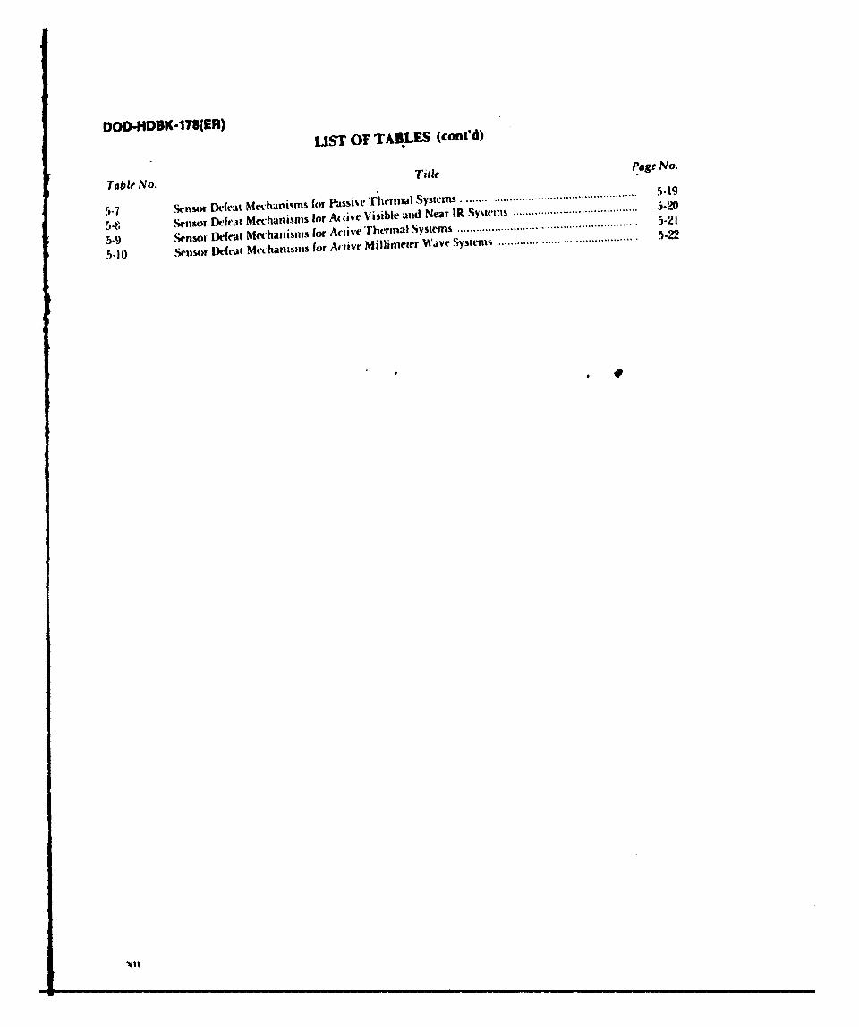
DOD-HDBK-17S(ER) LIST OF TABLES (cont'd)
Table No. Ta5l-
agr No.
5-7 ensor Deft'at Mechanisms for Passihr Thermal Systems ..................................................
5-f, snsor Dticat Mechanisms for Active Visible and Near IR Systems ........................................
5-9 Sensor Detat Mechanisms for Active Thermal Systems ....................................................... . 5-21
5-10 Sensor Defeat Mechanisms for Active Millimeter Wave Systems ............. .................... 5-22
S4 1
DOD-HDBK-178(ER)
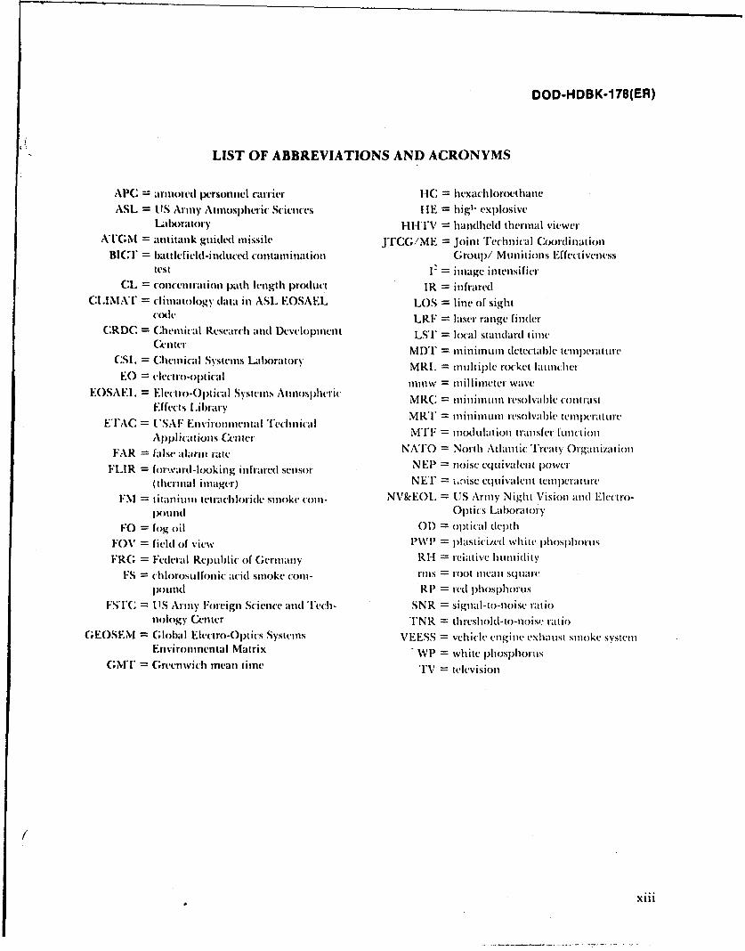
LIST OF ABBREVIATIONS AND ACRONYMS
APC =iriored personnel carrier IC = liexachloroethaneASL = LIS Army Atmospheric Sciences HE = hig" explosive
LIXh'atory HITIV = handheld thermal viewerATNI = antitank guided missile JTCi;/ME = Joint Technicall Coordination
BICI'= battlefield-induced containation Grou)/ Munitions Effeuivcncsstest 12 = image intensifier
CL = concentration path length product IR = infraredCLIMAT = climatology data in ASL EOSAEL LOS = line of sight
code LRF = laser range finderCRDC = Chemical Research and Development LSI' = local standard time
Gnter MDT = minimunm detectable tCel)craturc
CSL = Chemical Systems Lalx)ratory MRL = multiple rotket launcher
EO = electro-optical 1mw = millimeter waveEOSAEI. = Elecitro-Opiical Systems Anosplihric MRC = n ini um resolvable onIrast
Effects LibraryETAC = USAF Environental T'echinical MRT = minimum rcsolvalh ttcnc)crature
Applications Center NATO = Nodulation transfer functioon
FAR = false alarm rate NATO = North Atlantic Treaty OrganizationFLIR = forward-looking infrared sensor NEP = noise equivalent power
(thermal imager) NET = i.,ise equivalent tenperature
FM = titanium tetrachloridc smoke com- NV&EOI_ = US Army Night Vision and Elcclro-
ipoind Optics LaboratoryFO = fog oil 01) = optical dL)th
FOV = field of view W' = plasticized whitc phosl)horus
FR; = Federal Republic of Germany RI-I = relative humidity
FS = chlorosulfonic acid smoke com- rins = root iean square
plound R1 = red phosphorusFSI'C = IS Army Foreign Science and lech- SNR = signal-to-noise ratio
nology Center TNR = threshold-to-noise ratioGEOSEM = Global Electro-Optics Systems VEESS = vehicle engine exhaust smoke system
Environmental Matrix WP = white phosphorusM;iT = Greenwich mean time TV = television
xiii
DOD-HDBK-178(ER)
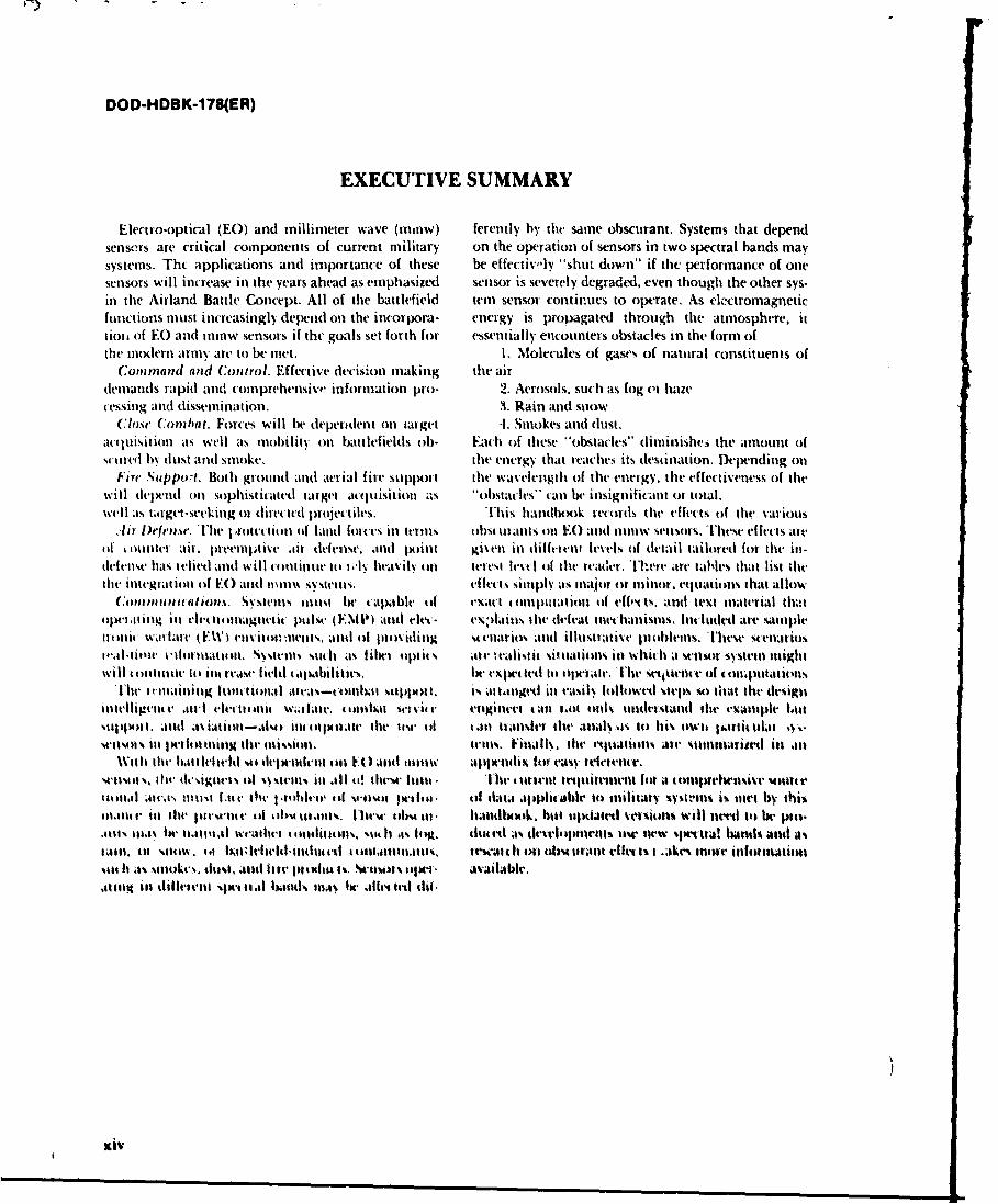
EXECUTIVE SUMMARY
Ekectro-optical (EO) and millimeter wave (amnw) ferently by the same obscurant. Systems that dependsensors are critical components of current military on the Operation of sensors in two spectral bands maysystems. Tht applications and importance of these be effectiv, ly "shut down" if the performance of onesensors will increase in the years ahead as emphasized sensor is severely degraded, even though the other sys-inl the Airland Battle Concept. All of the battlefield tern sensor continues to operate. As elcitromagneticfunctions must increasingly depend onl the incorpora- energy is propagated through the atmosphere, ittiot of EO and iniw sensors if thc goals set forth for essentially encounters obstacles in the form ofthet modlern arm%, are to be mnet. 1. Molecules of gases of natural constituents of
Comm nand and Control. Effective decision making the airdenmandls rapid ande comnprehensive information pro- 2. Aerosols. such as fog vi hazecessing anid dissemination. 3. Rain arid stiow
Close Cornl/mi. Forces will het depeittdent onl target 4. Smokes and dust.acqluisition ats well ats mobility onl battlefields oh. Each of these '"obstacles'' diniinishv6 the aimount (ifSCUweel by dust ant sinoke, the energy that reaches its destination. Depending oti
Fire Sadppwrt. Both grounid and aerial fire sttippxnt the wav'elengthi of the energy, the effect iveness of thetwill depenid onl sophisticated tatget acquisition as .1ohstacles" can lit insignificant or total.well as target-see-king om climeeteti projectiles. This handbook records the effects of lilt- various
,-Ii lDefense. 'thle r'ottectiol (if lanid force's in terilns ohst urlants tin F.) and 1111w sensors. These effects airof touniter air. premplti%.e lir defensew, and po~int givenl in diffemenal levels (if detail tailored for the ill-tiefenlse has, lelied and will coutinue it) ]-I% heavilv (tit Iteresa level of the reader. There are tables that list thethe initc'gatiou oif EC) andI iimllu systems. effet , sillply as major or mianor. equations that allow
Commnt,.afhopt,%. Sy.Stells inusa he tapable oft teXil I c oan11111amOn Of f"( 11. and tVst material thatopem .ating in eletroluagnetic puls, (ENflP) and elet- evieains the deea inllnislus Included are sainpleare nut w,1malt (famE) eln itoln Iltenas, anld Of 11teividing utcenarios antI illustimltve pi cblents. Tlhewv sc enuai.sle'al-ailuec. i orniatioti, svstemns -.uill as libel opt its. Me !V;Ilist it situations in whlich a stcnscit systeml mightwill tooanmue. tot inq es field 4aishihities. 1wesecte to opiemam. Thr *vctuence ti of l c oaptation..s
Iw ail Icinainimig twiliita l area%-ommhaa s1plint. is aagtle tin ra~ilv followed steps scl that lte designintelligete .ini elee titanlic W . kite. omohat41 "(1611 cr enwa tall mItbt eenl undlertand thr exauple ImtsetpafXea . antd msiat itk-alilt me1 lull~ alt. ltic 1Use of tanm tranlsfer thev ;AmIias it) hi\ oWit l~irltull q.,M111 inei s am f'aftm laing tilt anlisiomi. tell%%, Filmiv. the1 etfuatictIs1 air'stiuitie na
With% itle Imttefel eadewnka iaN),mal mu ~awlih fto easy treeencr.setisOm , Ow kige' oftclmm ie ll 11 ti e luar u l 1te (tartt rttikrilnn (fit a I ollptrheni.v -oultet10a1,11 *uv~v, limatt 1.1ctm 411 1medefei'1 & e lf i iviso t si e of d6ta applic able to mIilitatr %Vstr'ans i% met0 by this111,411t. il tlte pirewemt Ill ohs.ul.1mnts. [hlew IlhAsta.- handbooilk. htat tltxi;Al vel%411ti will netl it) I. pieo.m.m ama.4%l uJI01mailetal vete 4 uinfime %1a4 Ii s o t, dth tit ak drevl'ptmweIl use new sperua! bandstl and a%1411,tmsatw eifatlla'd.adj 01l %0W cailtii#its r tti It On Ohm. earant Ofne t' a ..ikes more ~I utiiiititt%~t It ;1s seuilok'.. fust .uad flt-e prtiat a1 Saioa oll ' availAble..411IR Ili jiilm clff'emusjtial 61ands a11.1% Ie. .4eflet l till
xiv
DOD-HDBK- 178(ER)
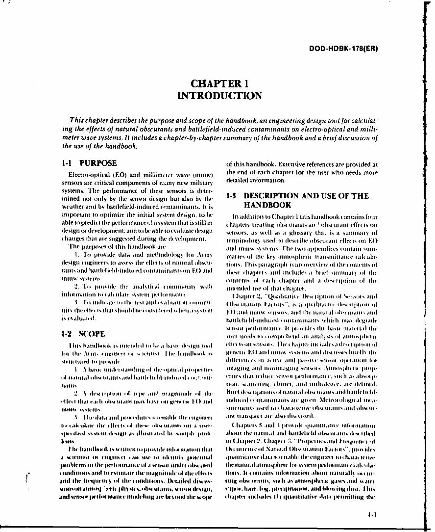
CHAPTER 1INTRODUCTION
This chapter describes the purpose and scope of the handbook, an engineering design tool for calculat-ing the effects of natural obscurants~ and battlefield-induced contaminants on electro-optical and milli-meter wave systems. It includes a chapter- by-chap ter summary oj'the handbook and a brief discussion ofthe use of the handbook.
1-1 PURPOSE of this handbook. Extensive references are provided at
Electro-opuical (E0) and millimtner wave (minw) the end of each chapter for the uiser who needs moresensors are critical components of muany new military detailed information.systems. The performance of these sensors is deter- 13 DSRP INA DUEO Hmnined not only by the sensor design but also by the 13 DSRPINA DUEO Hweather andc bv battlefield-idticed ce' ntaiinants. It is~ HANDBOOKimportant to optimiie the initial svstesn (lesigil. to he Ini addition to Chapter I this handbook contains fintrable to predict the perforniatn e t.I a s tet that is still II chapters treatting tobstiatitsl aI obstutlant effects onldesign ordtevelopatent. and to 1w atle toevidtl e sigt selsors, ats %%ellI as it glossarty that is at sitiitaty ofchanges that are suggested dtrinig lite dc 'eloptnen . ter'minology tistd to (lesci ihe obsurant effects oni E)
'[he ptirposei, of this Ivtinlh4)k are anld 1t1111% % stemls. The two aptwnit es ( ccintas M.11.'o Provitde data and tnetkololc Iy fill At1l11% maties of lite ke-y atmosphesit( titnscittanitt eahiila-
design enigineers it) asses.. lit- ellet ts of nlattitl at 11)% It- t ionls. Illh is patI agiapttl iS an oser itw ol thetoltvrils oftans aitlbas leeldinut it ontsniant onN)and h tapters. atild intliudes it it stilllty (A lit,
11111w Nyqtetns (otttettts tat eat I t haiptt and a demti iptioll 0I the(2. 1e I pt s dt. tlti anlhtitA at t nliutilti withi ilntetdst04 ut* Of that1 Ihaptet
itifoit 1alti it t.11 1t .ttat i~ti-Il I Wkto I tt 111t C hapter 2 '.t1.tai 1)c it ion otf%~.t atitfl. Ft itiie at(- it) thlu tt,%t .1nd is atitaion tooiit. 01)"t titatitatl Fa.tll. a tftlaltta11%vdi' tl'sc liiol of
t% thte lk. is ht hud1 eistttrht 1% 11,1 F0ll 1)( 1nd111tw wttsol%. atitl ilt,' ttatiial os tat' ttIstktated. I)tttitltittt ~ tttitnswhiti Itl tat~cltait,
1-2 S(:OP seust-a filt teat ma r, It tate %is td lite asit "11,14-6.4 la ht1-2 COt kiel tte. .i t~ tt't a111a~ i otflstsltiI
I ttts lileldlbilk Is 1tt'tt I' it - jw hi asl( elesiit tool ifit Ieiollt 5tt~ lts it-4 hata4.lt ilt little's a dc'N t Ipt1ie ti
%it tititI tts f1el4% t'lilt-tii t-1t4Cs to t tr Atitl %cii oC scus1ol ot tA. .% st l tdt lstn ito till' optcal pegw1ie11.1mitiq .attel 1114111.i Wt4ls AtteallttI
tof t1.4t111.1t tIs tt i s t11% ltt1 lui let1 iti- 1 tit tt 4 cc )W A, oll- t't h a l~t Ittitt' silts'11 it p 111 feat n t " r, tithi .1 1is ltlil %441, 1g 4ti I itg. i titte f u' ill ho 1' . mt' - ~th- 'il.
2 A iltmls t w l 11411sl t pejx meil tttagIttttcl'' tf ' Bt 1460 tt-st 111b1 tills i1t 11.11111 .tltist 111.611t .It tt l lt'livged-
cit'tthat a l e ' 16 b4 t11 ,t11t 111.15 ta 1.%t it l Itt c l tO .ittd itteteitil f ee11 till lbltait at Mr igis-tt Ae etalit lIlia.1
lotltatt it , se till ii 4lr .41%il11%tl Atl '14l 0 t at ndwt e I ttitat tillC'11161t.1115ait v15 t
I 14 li (i .~t te ~ tiiselttbe fe 'tltil11.11.lts12. *tlsor 15 "I lot1154 1 " 114 441t.1iio
SIt it 11fid 1% 'hilt iii Itn ts Ili 'l 15 Vltgitt 111.t tal *liI te11t.11 il a t .nl 011tt-ttlt 1. l till l 11itts tati.
A -A ' VI1lt Ofttdbeact. I 4 .44 ttt' tir It& as ilt 141 Itta 4-lealt t~.. (it itiattc ii 41, tIl a 1 1.1 rittl Ft-I tels 1111)5 U Iclt.1911111 M f~is t ' t I61-1tti4 t' it ise to il.-t 11 fs1V 1111-tIAi~ flit- itit.l1s .tt llWIi it e- the listt lilt a ll ll a e
- * ta01li4gt ti. aitilt te stt.t lilt, 11titittal citi tttt 11140t.4 I% licilms t el~t I lit it . 1 6111t i 11cu 1 t 411t;tfl% 0cxi it-
J1t41t ttti tttIlt 'tttVl e Ill tlt- etlktilibcits. Dale t d ti-As its - ftlI ows twiltis %tilt% .ts al fll sI)tItII 4 ga1.ts . itjt sis~tlt~ti)Jtttt)S ilt 11% %it %. law litijti 01% M1104 tlc'SX11. fi. t.. P14. fatt tpitaatutt. and blowisix thols. Iltis
JIltl 511M501 wtftttttitt. 1ttt*iciiir li t-tItl the M~ tqu'- 11.4t~11)4 it esdi (It cIitlLIr iiatta jk~llitiit lit-
F,
DOD-HDBK-178(ER)
calculation of atmospheric transmittance through the Appendix A is a summary guide for calculatingnaiturally obscured atmosphere; (2) qualitative descrip- atmospheric transmittance; it includes references to thetions of the climatology of four geographical areas required data and equations in the handbook. Appen-(temperate, tropical, desert, and arctic), and (3) quantita- dix B gives equations for converting between differenttive descriptions of the frequency of occurrence of natu- measures of atmospheric water vapor content. Theral obscurants in those areas. glossary contains definitions of technical terms used in
Chapter 4, "Physical Properties of Battlefield Obscu- this handbook.ration Factors", includes a quantitative description of Trhe handbook is d signed so that it can be used tothe battlefield-induced contaminants discussed in obtain either qualitative or quantitative information.Chapter 2, including smoke, munition explosions, Trhe engineer who needs an overview of factors affectingvehicular-induced contaminants, and battlefield fires. sensor performance can obtain a general understandingThis chapter (I) describes the battlefield-induced con- of obscurant effects from Chapter 2 and can refer to thetaininants, (2) provides mass extinction coefficients, defeat mechanism tables in Chapter 5 to see whether anand (3) gives an assessment of the concentration of those effect is potentially major or minor. Qualitative descrip-contaminants that might be found in a battlefield tions of natural and battlefield-induced contaminantsvnlvironinent. 'hree examples are developed-for artil- are given in pars. 2-4 and 2-5, respectively. Quantitativelery fire, obst uring smoke, and tank-generated vehicu- estimates of natural obscuration can be developed fromIa dust-to indicate anticipated Ievels of battlefield- the data in Chapter 3. Quantitaive estimates of battle-induced (ontatminants. field-induced contaminants can be developed using the
Chapter.", "Obscuration Factors and Sysiem Design", data in Chapter 41. Individuals who have a generaldis( usses Sellsol perforilnni Inasures and gives illus- understanding of the subject may go directly to thosetiat ive exanmples of selsor pea1 flrmlante catulations. chapters for quantitative information. The scient ist orl'his chapter (I) introduces SN stein l.rforulattce inca- engineer who needs to pet form systems effects calcula-Stitt's lr lhe classes of systetms destribed in Chapter 2 tions may refer to the descriptions of performance inea-amid shows how they aii used to det.-.rinite p'rlonaie. sUTres in par, 5-2 and to the sample problems in par. 5-1.(2) disctsses sensol delat uiitec'hatnistls in tle obscured Ihe sample problens are step-by-step illustrations ofinatural alld battlefield en'iiltnnllients, anid (3) "walks" how to tise the data developed from Chapter 3 andlthe user ihrough sample problems illustrating the Chapter-1 to tal ulatc the performance of a sensor in antfilects ol obstmlaits oil those systems by tsiig tlhe obutred atmosphere.qunlitati(, data dehveloped ill CUhapters 3 and 1.
1-2
DOD-HDBK-178(ER)
CHAPTER 2QUALITATIVE DESCRIPTION OF SENSORS
AND OBSCURATION FACTORS
This chapter contains a qualitative description of electro-optical (EO) and millimeter wave (mmw)sensors, and the natural obscurants and battlefield-induced contaminants which may degrade sensorperformance. It provides the background needed to perform an analysis of atmospheric effects on sensors.Par. 2-2 describes generic EO and mmw systems with a brief discussion of the differences between activeand passive sensor operation for both imaging and nonimaging sensors. Par. 2-3 defines atmosphericproperties that reduce sensor performance-i.e., absorption and scattering, clutter introduction, andturbulence. Pars. 2-4 and 2-5 include brief descriptions of natural obscurants and battlefield-inducedcontaminants, definitions of the terminology used to describe them, and a discussion of the meteorologicalmeasurements used to characterize obscurants and obscurant transport. Quantitative descriptions of thesenatural obscurants and battlefield-induced contaminants are contained in Chapters 3 and 4.
2-0 LIST OF SYMBOLS n(X) = real part of index of refraction, dimen-sionless
C(r) = concentration at point r, g/m 3 nf(X) = imaginary part of index of refraction,CL = concentration path length product, g/m2 dimensionlessC. = inherent contrast, dimensionless P = air pressure, mbar
= apparent contrast, dimensionless P,,(X) = emitted power, WC; = index structure parameter, m -2- 3 Q = extinction efficiency, dimensionlessCT- = temperature structure parameter, K2/m2"3 Q(X,r) = scattering efficiency, dimensionless
dL(X,r) = change in spectral radiance, W/(m2sr) R = path length, kmdr = distance, m R,(X) = sensor spectral rcsponsivity, V/W orE = spectral irradiance, kW/(m2
1m) A/W
Ef = efficiency with which aerosol is dissemi- r = particle radius, innated, dimensionless T = temperature, K
h = altitude, n T, = effective atmospheric transmittance,i = imaginary operator, dimensionless dimensionless
L = path length through obscurant, m 7Tri) = temperature at point ri, KLb = background luminance, cd/m 2 T(r2) = temperature at point r2, K
= apparent luminance of background, T(X) = atmospheric transmittance, dimension-cd/m 2 less
Lb = obscurant luminance, cd/m 2 T,(X) = contrast transmittance, dimensionless
L* = luminance of horizon sky, cd/m 2 T,(A) = transmittance through obscurant,Lb = object luminance, cd/M 2 dimensionless
U. = apparent luminance of object, cd/m 2 Yf = yield factor, dimensionless
L, = atmospheric path radiance, dimension- c(X) = mass extinction coefficient, m"/g
less et(X,r) = mass extinction coefficient at point r,L(X,r) = spectral radiance at point r, W/(m2 sr) m2/g
I = distance between points r, and r2, m y(X) = volume extinction coefficient, m -' orkin '
M = mass of particle, g 0 = scattering angle, rad
M. = mass of aerosol in munition, g X = wavelength, jum
M' = mass of obscurant aerosol disseminated p(r) density of the medium, g/mby a munition, g a geometric cross section of particle, m 2
m(X) = complex index of refraction, dimension- a, = scattering cross section, m 2
less a,(O) angular scattering cross section, rn2/sr
2-1
DOD-HDBK-178(ER)
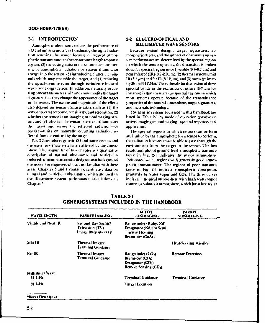
2-1 INTRODUCTION 2-2 ELECTRO-OPTICAL ANDAtmospheric obscurants reduce the performance of MILLIMETER WAVE SENSORS
EO and mmw sensors by (1) reducing the signal radia- Because system design, target signatures, at-tion reaching the sensor because of reduced atmos- mospheric effects, and the impact of obscurants on sys-pheric transmittance in the sensor wavelength response tern performance are determined by the spectral regionregion, (2) increasing noise at the sensor due to scatter- in which the sensor operates, the discussion is brokening of atmospheric radiation or system illuminator down by spectral region into (I) visible (0.4-0.7 Mm) andenergy into the sensor, (3) introducing clutter, i.e., sig- near infrared (IR) (0.7-2.0 MAm), (2) thermal systems, midnals which may resemble the target, and (4) reducing IR(3-5Mum)andfar IR(8-12pm),and(3)mmw(plimar-the signal-to-noise ratio through turbulence-induced ily 35 and 94 GHz). The rationale for discussion of thesewave-front degradation. In addition, naturally occur- spectral bands to the exclusion of others (6-7 pm forring obscurants such as rain and snow modify the target instance) is that these are the spectral regions in whichsignature, i.e., they change the appearance of the target most systems operate because of the transmittanceto the sensor. The nature and magnitude of the effects properties of the natural atmosphere, target signatures,also depend on sensor characteristics such as (I) the and materials technology.sensor spectral response, sensitivity, and resolution, (2) The generic systems addressed in this handbook arewhether the sensor is an imaging or nonimaging sen- listed in Table 2-1 by mode of operation (passive orsor, and (3) whether the sensoi is active-illuminates active, imaging or nonimaging). spectral response, andthe target and senses the reflected radiation-or application.passive-relies oi naturally occurring radiation re- The spectral regions ut which sensors can perform_fieted from or emitted by the target. are limited by the atmosphere; foi a sensor to perform,
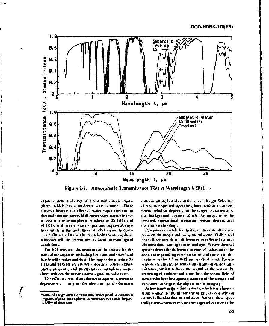
Par. 2-2 itltroduces generic EO and nunw systems and the radiation it sense must be able to pass through thediscusses how these systems are affected by the atmos- environment from the target to the wnsor. The lowphere. The remainder of this chapter is a qualitative resolution plot of ground level atmospheric transmit-destription of natural obscurants and battlefield- tante in Fig. 2-1 indicates the major atmosphericindtwed (otaanti nants and isdesignedasa barkgtound ".windows" -ie., regions with generally goxd at mos-disctussion for enginetrs who are not familiar with these pherit transmittance. rhe regions of poor transmit-areas. Chaptrs 3 and 4 contain quantitative dla oil tance in Fig. 2-1 indicate atinospheri absorption,natural and battlefield obMiurants, which are umd in primarily by water vapor and C01. The three curvesthe illustrative Nystem iWtforillante takulatioms in inditate a tropical atmosphere with high water vapor(:tailer ,. tontent. a subartli atmosphere. which has a low water
TABLE 2-1GENERIC SYSTEMS INCLUDED IN THE HANDBOOK
ACtVIE P SvtWAVELENGTH PANSIVE IMAGING .ONIMAGING NONIMAGING
Visible antd N-at IR F. antd 1)aS .ights* Kangelindet (Ruby, Nd)rlevisim (TV) lk)signatot tlNd) It Semi-
Inage Intetnsliejt (1:) attil linminKScainridet ((aA,)
'Mid IK i'brmal Imager hra.l.crking Mimilvs'rrminal Guidamcr
Far 1K Theinal Imagrr tagtolfindet ((X)a) Retket tntion"rminal Guidanre Bkamridr (CX)l
Dignatnm (CX)J)Rmuxe Sening (MI)
Millimeter Wavr3 GH Terminal Guidantr Terminal Guidanm94 (Ha Target Lxation
1)imt View 0hmics
2-2
DOD-HDBK-1 78(ER)
Suarei
LI
87 .4-
18.2-
8 1 2 3 4 5
Wavelength A, m
* Subarctic Winter
0.~4
65 ts~52 25
Wiseength X~,
Figure~ 2- 1. Atmosphtrik Transmittance T1A) vs Wavelength A (Rdf. 1)
v~alp ontmn. sand a tyical VSi ot tidatitmir atmcm, twunttation) bill ilvmnon the W11%ol drsign.sle ttinphre. whit h ha,. a modekrate wattrt 4 onten. lhI'r ~4 a wn~of %ptrtral opotaing band within an aimno-cure *tfutair the edffts of watei Vatlt totern 4M phtt window drpcntI% on the tartctha* £tu .
therstial lnantniitanr. Ntiinitr wav-r Itanqotarwe* the bat kigtund agauimi witith the target. inu hek~ be In the ait iphtiit witdow ma 35, Glit and dytttd. opjwintauI rnatim. wnous detign. and94 (4-1. wih ",etc Wgs.'r *Att andl otyK~stm "u. tnaertiAl 101;1hnu4t ,
wi, ht' io tual tran~ttittanve within thramrtsioprti: btiwern the targt an d bat kgund u enr. \*iibkr andimindowt, will br tlrtiminvil b lucil #nlt'm-#lt4*ka1 "eat IR wpn- din Idifetent c% in telfitrld natutal
co~ndiiint. (lmntinin a 1# niuuu1tap1h. PJ416%it- thrtlttidFor l() tem% .oba urAtion tan bt tw 6 a1'itt q* Ik eec the difi ktntt' in emitted raiauiu in the
natural aitmuphete (inludinglog t .sk, anwl tnnwasd Met mt wn ponding to tempetatut and vt"iivitv Ci-battlefield %nkc and dum. 11wmuj..-o *utamesat1 fereate in then 1-53 ot .12 Pirn fwimtrai band. Pa...%r~Glit and 94 G Mt air .iirrjnd&dtt. ainnrn tra~vw art afirttd bf tedutii in ateinht-ic Iran%.$4lit motkiur. and psrripitatin ouioukiutr vxve- milvanc'r. which milk"mi then %ifnaI as th Wrist": hVutims miur then msw atiitin tigt~a~uko-"w yatia. *itsh'tin1 of ambint tashatiun mmsint h enux filud ofn
'IVi in(10%,~ rw, of an obwunan alpilh, a wln i*, view (frWuiflg thOw appaent toiifatii of the taltit); andlcfrpvrn k. mly an then obtcurant (and obscuaa by clutter. ca ulargins.ike skjinn in thintagrty.
Atliie urgw urfuision syiknwni. which mew a 6a, or
Lssnimcdvaswr iroveto twmia "my~ br dnlt too ei lamnpow toni ilinstn then tare. do num Mry an"%was of f*wx awnosbie ussnus liminsth d rs natural illumination or eintin. Rather,. thewer epinsibility of dmwiwn, orally tuarraw *mums renly on then tArgni ftfn taiu i at thn
2-3
DOD-HDBK-178(ER)
illuminator wavelength to provide the sensor signal. tion by small haze particles in the atmosphere. The
Active systems generally use coherent sources, such as atmospheric transmittance in both the visible and near
lasers, rather than broadband (incoherent) sources. IR regions scales rather closely with visibility, except in
Coherent sources are spectrally very narrow and have a extremely clear weather when absorption and scatter-narrow spatial beam divergence which concentrates the ing of radiation by gaseous atmospheric molecules areilluminator energy in a narrow angle (usually 0.1 to 0.5 the only remaining factors. Changes in absolute
mrad). The narrow spectral line width permits spectral humidity have relatively small effects, except in theirfiltering of the detected signal to reduce background contribution to aerosol particle size growth. Rain,
noise. Active systems may be affected by (1) the reduc- snow, and fog reduce tile effectiveness of passive imag-tion in atmospheric contrast transmittance, (2) changes ers by reducing atmospheric contrast transmittance and
in target reflectance at the illumination wavelength, by reducing the natural illumination level. They scatter
and (3) atmospheric scattering of the illuminator energy active illumination. Snow cover also changes the target
back into the system receiver, which may cause false contrast. Cloud cover, by itself, reduces the performance
alarms. Multiple scattering of laser radiation by fogs of passive visible and near IR systems by reducing the
effectively increases background at the illuminator ambient illumination.wavelength. Systems that depend on laser sources arealso particularly susceptible to (1) atmospheric turbu- 2-2.2 THERMAL SYSTEMS (3-5 and 8-12 Mm)lence effects, which can cause spreading of the illumi- Systems operating in the IR spectral regions includenation, (2) beam wander, which reduces illumination passive mid JR (3-5 ym) and far IR (8-12 Mm) thermalon the larget and at the receiver, and (3) beam breakup, imagers and terminal guidance systems, some modernwhich is seen as a "spottiness" in tile illuminating missile seekers (4-4.5 gm), and active CO 2 (10.6 Mm)beatm. rangefinder, designator, beamrider, and remote sensing
systems. Active coherent imaging systems using CO 22-2.1 VISIt. ND NEAR IR SENSORS laser illuminators are in development. Older missile
(0.4-2.,, n) seekers may operate in the 1.7-3.5 pm spectral region
The Visible spectral region, 0.4-0.7 pm, includes because of detector technology limitations at the timethose wavelengths of radiation to which the human eye they were designed.is sensitive. EO systems operating in this region include Thermal imaging systems* detect and image the nat-direct view optics, TV systems, and ruby laser range- urally occurring differences in radiation emitted fromfinders. First and second generation image intensifiers or reflected by the target and the background scene. The(P) operate in the 0.1-0.9 pm spectral region, which imagery is generally not affected by ambient illumina-includes both the visible spectrum and part of the near tion, except in the presence of IR-reflecting back-IR region: second generation image intensifiers operate grounds, such as water at shallow grazing angles. Ain the 0.6-0.9 pm band. TV systems, depending on the thermal signature of a target is usually expressed as thephotocathode or photoconductor used, may respond to temperature difference in kelvins between the averageboth visible and to near IR radiation. Neodymium laser target temperature and the background temperaturerangefinders and designators operate at 1.06 pm. referenced to a 300-K background. For ambient temper-
Visible and near IR passive imaging sensors use ature targets, the radiation peaks at about 10 pm. Forambient radiation reflected from the target and target hotter targets the spectral peak shifts to shorter wave-background to form the scene imagery. Daylight sys- lengths. For aircraft engine exhausts, the peak is in theWis, including the eye, direct view optics, andday TV, 4-4.5 pm region. For active systems such as CO 2 laserdepend on reflected solar radiation. Image intensifiers radars and rangefinders, the target signature depends(12) depend on the reflected night sky radiance. The on the target reflectance at the illuminator wavelengthimage quality of these systems depends on the level of rather than the target temperature.ambient illumination, the relative reflectance of the The atmosphere impacts the performance of EO sen-target and background scene elements modified by sors operating in the thermal band by reducing theatmospheric contrast reduction, and on the sensor apparent target signature by transmittarce losses andresponsivity. Atmospheric contrast reduction has two by weather-driven changes in the target signature. Pathprincipal causes: (1) radiation reflected from the scene is radiance is not significant except in low visibility con-attenuated by absorption or scattering and (2) stray ditions or over long distances. Visibility is not in gen-radiation is scattered into the sensor. In nonitnaging eral a good indicator of thermal system performancesystems, atmospheric absorption and scattering reducethe signal received from the target and inclease noise. *Forward-looking infrared (FLIR) systems are thermal imag- )
The primary natural atmospheric effect in this spec- ing systems developed for use in aircraft; the acronym FLIRtral region is aerosol extinction, the scattering of radia- is often used to indicate any thermal imaging system.
2-.1 Best Available Copy
DOD-HDBK-178(ER)
because thermal systems are relatively insensitive to mance of mmw sensors. Fog reduces transmnittan-ehaze. They are, however, affected much more than visi- because of the increased liquid water contei I theble systems by variations in atmospheric water content. atmosphere. Rain and snow scatter and absorb mnrwThe primary mechanisms for atmospheric extinction radiation; backscatter from drizzle can cause seriouswithin the thermal bands are water vapor absorption, signal-to-noise degradation.CO 2 molecular absorption, and aerosol extinction,including water (fog and clouds). Increases in absolute 2-3 FACTORS THAT AFFECT EO ANDhumidity significantly reduce the transmittance in the MILLIMETER WAVE SENSORthermal bands. Higher humidity conditions may also PERFORMANCEreduce transmittance by causing aerosol particle sizegrowth, particularly in the salt spray particles of mar- The atmosphere reduces the amount of signal radia-time atmospheres. tion reaching a sensor from the target. It may also
Aerosol extinction due to rain, snow, and fog signifi- introduce noise in the sensor band and reduce signal
•dntly degrades thermal sensor performanc e by attenuat- quality. The atmospheric parameters used to character-
ing signal radiation and scattering background radiance ize this signal degradation-atmospheric extinction,
into the system detector, which increases the noise level, transmittance, contrast transmittance, and turbulence-
The extent of extinction due to fog depends strongly on are defined in the paragraphs that follow. Clutter is
the aerosol particle size distribution and cannot be pre. defined in par. 2-3.5.
dicted solely from visibility. Aerosols of maritime 231 EXTINCTION-ABSORPTION ANDorigin degrade system performance inure than aerosols S CTINGof continental origin: in low visibility conditions (less S.ATTERINGthan 2 kin), sensor performant e varies strongly with Extinction isdefined as the reduction. or attenuatioin,aerosol type. For attive systems. arkmatter froin nitt. of radiation passing through the atmosphere. Extinc-ral aerosols must be (onsidetred bet atuse it will in( rtase tion comprises two progesses: abstrption of enet gy andIoist. at the illuitination wavelength: in mnloderatr t) Uattiteing of energy. lit a1)rl4tiot01 a )htito.bf adia-heavy rain. ,tow, and fogs. multipli" xatterintg effets tion is absorbed by an atnospheric n1olettle oi allmnust alm) s e t onsiderrd. lot noninaginig at tive s. n. aetosl partictle. In scatterintg. tire direr tiont of tht int i-wrs. the iinpac t of added in-hand itose i%5 a de teast in dent radiation is, thanged by tollisionN with atilosi,-target a. t uiitltt pol,' hilit alind all in. lteas in false pherit inolt'ules tit aerosoil prtit le. Atntiosphetitalatrm ate. extinction depetndS on tile tyle. %iet', antl I)( t'ittatiill
Piot wrathrt A) drtatIadN pa'sli lheltal ilagxt of (tt atn1t11ophevit toritittl tilthe wascrlentth oflrlotttantr b trdiuc iti ilt iltalget ignattle. In o ste the c'let ttlltivgn'it tadiatitn..,t Ai tidititot target aitd Nit kLtound siKnatrte If Abuorplitt of radiation by aittmnopliit gas-, andpassis trgeltstt tlo wash oult'' iftunrmtn37. water saptor tatses ignilikant i-stint titc in the IRaltur.. At lir tautr1t %ot It as efeit ied latk% izta., how. aoods. Abstiptiot isttttly w A',a length detltdritt:Cete. ,tattd ot1 Moore tOgl agains itiM I at k tgrtd, the abtorptionit waer-ngth in tirtrnloond to theRait id 'WOw tcul the tarts bAndh krL9 1O0tds,. irtttttgy dillertrntr betwern tin- dilfrcnt tolaittnal andwhit It It-, 1 toa r unilli,.. cl ptrituve diiltibu- vibratiotal %tatr% tot atinotphrti. ontile- ult. Ab,,utitn at tos lhe u tire. Rain. %noo . and wet fhgsalvsaltr lion b% natural .ttiitntphtit gasts. ins lidilng craiSr S1:4l taigKItattirt%- Ii hantging tile tartng' tatcit. is ti nslwd itt pat. 2.lII Absloititn ttsthollland imt kgruknnd rfil-. tan.. t htat titsti' . dmninatr s attrting at IR and mnw wascirngIths.
~.attlring is the mai otfat tot n t ssihle rstiltc uion frit
tnilaC'u alool jus itptlanl at IR arllth. ttm bi
2-2.3 MILLIMETER WAVE SENSOLS 35 ain alsd %flow intat at )hR seleuhe Iti .t ,ln1mtIA,and 94 GHs) tin mti snol -th mI attnott hatat trtoi4 m ss a .,tm.ti
Millimctnrt was.r applttaotts I otfrnt!s ttles drerl, i. lr ncuntilwd using a tattrvmnit ts t- nm lb,'opttnwnt in. hdr e5G(Iand94 (Illt titinali ttict..t- r a ttetin ' r 'tmo. isddciited asthat t set titv
se-Utnt, whith air m.tiw ttnamainlt sttrvns, And ofl an intidrot wave, a ttJ im by the lutti. I-. ha mug an35GIlt passit. nonimalging trtinal arquisititn atrasuth Itatal tht-ltwerflowinttmssit iritial 1t)senscts. the ttal powet watird''l in all divc'itotms. rhucOf l(vt'
Atniosphoric e'zlitn lion at inmw and tnat mmw fit- liwt-ness of an .tb want asa wtatlting medimtll ti'eclqtiu'itn is tominated by watirt npui. liquid water, on dlw raio of the obturant plttit le situe t" the taim.aand oitygen ab option. 1he ist "window'" in this tiun wait-lenlth. S.tattciing lettinc is gix'vn by thetelion air twat 35 Gila and Ht. Millimelt wave scatteting 4iirnry Q(A.r) which it the atio 44 the
s.ymenm preftwmnanr is gt'nrally unolaected by atmnm- tlttive uatteing crus %'lion of a pru h tiE I. radits rpevix hawe. Ion. rain. and snow all impait the pedor. to its groilmbli cress sirtliti as
2.5
DOD-HDBK-178(ER)
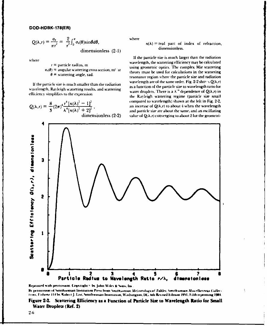
, - s _ 2 where2r "j os(O)sinOdO, n()= real part of index of refraction,
dimensionless (2-1) dimensionless.
where If the particle size is much larger than the radiation
r = particle radius, m wavelength, the scattering efficiency may be calculated
a,(0) = angularscattering cross section, m2 sr using geometric optics. The complex Mie scattering
0 = scattering angle, rad. theory must be used for calculations in the scatteringresonance region where the particle size and radiation
If the particle size is much smaller than the radiation wavelength are ol the same order. Fig. 2-2 shol, s Q(A,r)wavelength, Ray'leigh satierig results, and scattering as a function of the particle size to wavelength ratio for
•ekngth, aye t erixgresults water droplets. There is a X-4 dependence of Q(Xr) ineffiienuy simplifics to the expression the Rayleigh scattering regime (particle size small
8 r 4 [n(A)2 - 1]: comp;red to wavelength) shown at the left in Fig. 2-2.Q(Xr) k 9(2
4 an increase of Q(,.r) to about 4 when the wavelength3 = [n(,) 2 + 21' and particl size are about the same, and an oscillating
dimensionless (2-2) value of Q(X.r) converging to about 2 for the geometri-
4
C
C 3..3
'.
Par'tilel Raius to Walvelength Rtilo PA, dlI nIlonlI "s
Wrtlluxlorts ithtltilw, ll 00pSON1t1 C In .J40111 wlh'l 1,ltIOU
I8% I-141111%'moll i14%l wIll h1*44II1 PICl I M111 lellI~l ~l~~ .\0*11MA41"bl i TI ' ; \*IItfh samew" Vow,
MooItmusi C-6 .
11,o". 1,4NMr I I tI l wl J. ki.t %ilh,,mISAt In'AsI14114344 WA41641#14311. 1X_ th lrts" E41h1ti, 19'M, rl sl i ngl 19111.
Figure 2-2. -Sattering Effilde"g s a Function of Prticle Sie to Wavength Rtio for" SmallWater Droplets (Rtd. 2)
2.6
DOD-HDBK-178(ER)
cal optics region (shown at the right) in which theparticle size is much larger than the radiation wave- ,_Incidentlength. Radiation
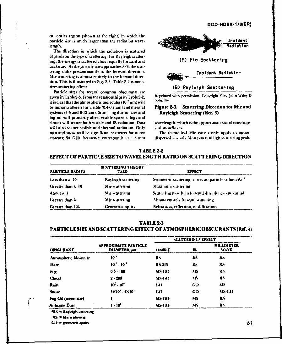
The direction in which the radiation is scattereddepends on the type of Lcattering. For Rayleigh scatter-ing, the energy is scattered about equally forward and (R) MIe Scatteringbackward. As the particle size approaches X/4, the scat-tering shifts predominantly to the forward direction. 25.,W t. Incident Radiatfe-Mie scattering is almost entirely in the forward direc-tion. This is illustrated in Fig. 2-3. Table 2-2 summa-rizes scattering effects. (B) Rayleigh Scattering
Particle sizes for several common obscurants aregiven in Table 2-3. From the relationships in Table 2-2, Reprinted with permission. Copyright Q by John Wiley &cit is clear that the atmospheric molecules (10- 4 pm) will Sons. Inc.
be minor scatterers for visible (0.4.0.7 pm) and thermal Figure 2.3. Scattering Direction for Mie andsystems (3-5 and 8-12 pm). Scar ng due to haze and Rayleigh Scattering (Ref. 3)fog oil will primarily affect visible systems; fogs andclouds will scatter both visible and IR radiation. Dust wavelength, which is the approximate size of raindropswill also scatter visible and thermal radiation. Only ,,id snowflakes.rain and snow will be significant scatterers for mmw The theoretical Mie curves only apply to mono-systems; 94 GHi frequent-y uorre'pl.xonds to a 3-mum dispersed arusul-. Most pa(tical light-sc'attering prob-
TABLE 2-2EFFECT OF PARTICLE SIZE TO WAVELENGTH RATIOON SCATTERING DIRECTION
S:ATTERIN(; THEORVPARTICLE RADIVi% ISED EFFEFT
lest than x 10 Raylhigh vattefing sviittnetri tattering; atlies as tpatlitle tlunt) -*4n 4
Greater than k 10 Mie materring Maxiuln %atitingAbout A 4 Mit' Mattering S .tteiting nunt in or.w twad ditt tion. vinre %jur*
(reater than A Mie Matttriltg \httost ailr h d ng i
Greater tih.tan lox (tetsne tpltitN Riferlon, ilast ti i, or dil rattiton
TABLE 2-3PARTICLE SIZE AND SCATTERING EFFECT OF ATMOSPHERIC OBSCVRANTS (Ret. 4)
.CATTER|NG" EFFECiTAPPROMIMATE PAi ML(1E MIUUIM"TE
01119MRANT DIAMETU, sam VVIMLE 1t_ WAVE
Atmnsphrt c Mol tuir lo4 RN ILS S-
Icaw 1(00 .MS-60 MS RSCFu -I 05,0 MS-.() , i% IKS
Rain 101- 10 (;O GO NI
Snuw 5Xl •XlO' G (R) MLi.(A)
Fogi l (mn Usi) I W-GO xS Its
Aitetwfte Dust I - 10v MS-Go) MS WS
OI- L aSnarogh artinxUs 0 MW-Su anGo - Imric apo, 2-7
DOD-HDBK-178(ER)
lenis will be related to polydispersed aerosol systems. Often an "effective atmospheric transmittance" T,Since the ligi, -scattering properties depend very strong- over a sensor spectral band is defined as the ratio of the
r ly on particle size, a mean or effective particle size is of received power at the sensor to the target signal emittedlittle value in determining the expected scattering power P*(X) in the same spectral region, weighted by theresult. A statistical description of the aerosol particle sensor spectral responsivity R.,(X)size distribution must be found, and an effective effi-ciency factor determined. It is found that this approach jI P.(X)R,(A)T(X)dXdampens the Mie resonances and results in lower scat- T, = ()dimensionless.tering efficiencies, with a smoother shape to the scatter- 4 2PO(jk)R4X)dX (2-6)ig curve. This broadband transmittanc- does not necessarily
2-3.2 ATMOSPHERIC TRANSMITTANCE scale exponentially with range because of the structurein the atmospheric absorption spectrum. To under-
Theatmospheric uansmittan(e T(Mowra specified stand this, consider a spectral region for which trans-path length, is defined as the ratio of the received power mittance at I km is 0.1 in half the band and 0.9 in theto the emitted power. It depends on the wavelength of other half. for a band averaged transmittance of 0.5. Atthe radiation, the length of the atmospheric path. and 2 km these transmittances reduce to 0.01 and 0.81.the type. size, and toncentration of the atmospheric respectively, for a band ave-aged transmittance of 0.41,constituents. instead of 0.25-(0.5Y.
For inotochroinatit (single wavelength) radiation, The designer should note that systems operating inthe change in spectral radiance dl.(A.r) across a distance the samr sprctral region and the samte atmosphere mayOf dr may he expressed in terms of a mass extintion be affected differently by atmospheric transmittance iftteffitient e4Ar) by thr target-sensor geonetry differs. Fig. 2.4 shows two
dirrtt view grometries: one requiring one-way trans-dL(,.r) = -*(A,r) LQ.r)p(r)dr, W (mi-st)(2-3) mittante through theatmosphtre tbeamridr )and one
requiring a two-way path through the atmospherewhere itangefinder). In Fig. 2-4(A) the radiation must be
I.-Ar) = xpet tal tadiante at ptoint I. W (it-%t) transtiittdiditant r X to he target fron the lar. andr) = density of the medlti, P. fit' ttattmitlante is given b) Eq. 2-5.
atA.) = mas*,extinttioniwjltietnt at point F. In the tanelimler application hown in Fig. 2.4(8)m g. the tadiation must be propagated to the target. rrtf l ted
til t hr target, and kw propagatrd bork to the "er.11ir mass extinc tion ttffi irlt is uWed to taltulae "u% te p1ath length R is twite the range its the tairt,
extil, lion bh o" I lltnts %Uth a% batlthirl smoke and I hee eh t itl a highly alttnualting atsisopher ist leatrlyAii'.iittrw dust. I eeh-wobvwuriants ra le a brod dis. muth mntr vrseir in the %nttmtl taw.tibultion (f patit IV sit and 4 nlatunitolln ttit ntrta. A thitd aw tr ta rs it the system nuot pwthotn o5 iiio t trr the w-ttsur-to-tags-t Path. twes diffrtrnt atnmusph-ris path%, a% itn lhe taw of the
If tW atstiet v phei it) tb ultiltfut. whit h 1, later tslsltatit shown 1n Fig. 2.5. I fete. the illumiit.the UtUal a.tJptitm ree a ttali" gtund rvTl tot err tett hhe% th target or Path I and i% reflrctepath. then the ritlinction lot a Ig itr aliosphrt- is Iothe inei-ros or Path. A otalitsliutlran suhawsitnply a luirliftn of the wavrlength of the radiation a sttlokc temo d in eithrt path presnrtl protrt q.,ot-nmAnd its atospherit path lrvg-h. It % an be eXpressed in 'r it.If the 416111) (f a sstrn tiepend tin Wns'lkIrlt In% a -olume rtilin tu bot iKient EA) at opetaling at twodill-tent wavrivngths, thernltserting
Anal 9i4 mui t coniidet both *pt tral rrlion%. A oirward-l(AkR drt mquir a taiget visuallv and desilgatte it.
usin a Nd:iA(; hlse dnilnatu. Ir a wieapon firw'dfrom atothe poit iioli. a in Fig. 2.5. In this taw, the
whetr -sptabitv N tthe y strm etrndt- ciin simial a quitrititmR = path kngth. kin. itatisrOAI0.7 pim lrammttiantr t" Path I). Usrtrt.
hal de-iltatiom (1.06 pu latu Itatinitiane s-r Path IF4* tviohroninat radatitm popgating thoulgh and Path 2). and suilul ase tking (1.06 pmt
the atmfsphere. lianmiuntvar TIM for radiatiom of lianuinantsr osv Path 2). Irtirituption of ti voualwarlegtlh A is gistn b% bier's Law as line of sight (1.%! mr 1,06 ipm IS on either lth for
slerlal svt ot; imW irsult in thr missile breaking lockT(A) = e"",. ditnensit onls. (2-5) on1 the taire. list, uulO IO is nrsr.srar fI drsil-na-
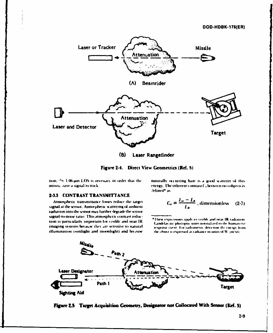
DOD-HDBK-178(ER)
Laser or Tracker MissileAttenuation
(A) Beamrider
Laser and DetectorTarget
(B) Laser Rangef inder
Figure 2.4. Direct View (eometrics (Re(. 5)
liol. "i 1-0-A [Ot .an IC)! * o m-m mr i l takn 1,11sbi th natialiv tiottutiti hair i% a ivant vJttrtf tA l %a
2-3.3 CONTRAST TRANSIMITTANCEAsft~bs t~fttfl ~IP%% rtaKI'II imtict th- - inrnsionlev (2-7)
it ilpt~ "i mt u rat .jw dlv .1 a'bl1r it ovta trlom 4%1*r tAn1a 14414'Sw~ n..qmurai t Olr kowljgua to-el
silutts lfItii (moullitthl jnst ttflumml~hl) and mlwt .4iiWr bi -srt 1% v urmtil A' atu~aar mn 411414t jtal ;m
Law O~ao
Path 1ro
SIOhtl Aid
ligure 2.5 Taai Acquisitiona Geometry. DvsIgn aot Collocated With Senom (Rd. 5)
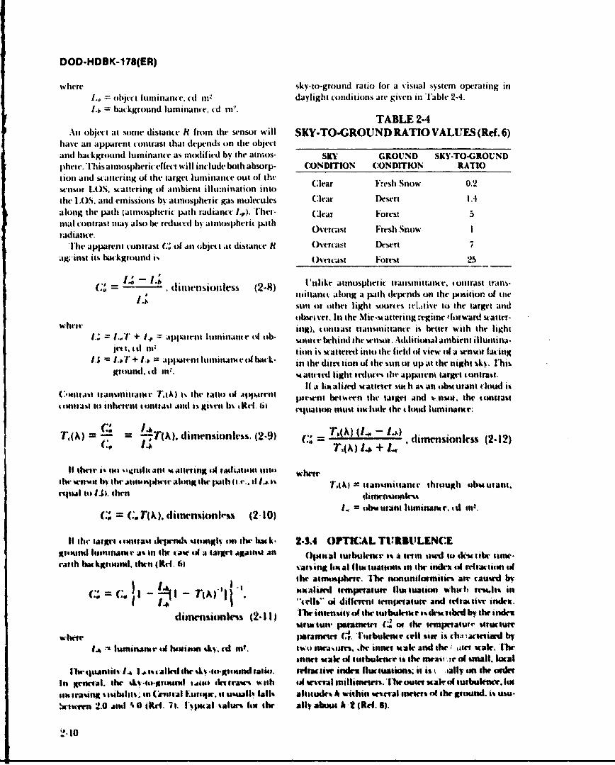
DOD-HDBK-178(ER)
w here sky-to-groutid ratio for a visual system operating inI.. = t)jt-(i luintanice, cl m2 datylight conditions art, given in 'able 2-4.L-b =background luminance, cd i?.
TABLE2-4Ani objec t at some distance Rt fromt the sensor will SKY-TO-GROUND RATIO VALUES (Ref. 6)
have ant apparent conItrast that depends on the objet _________________________________andl backgroundI lumninance as motl if itd by the atmtos- SKY GROUND SKY-TO-GROUNDp~heie. T'his atmiospheric e-ffec-t witll incluide both absorp- CONDITION CONDITION RATIOtion and scattering of the target luminance out of the(.erFshSo02sensor LO)S, scattering of atmbient illumination intorFes no .the LOS5. and emissions bsl atmosphrric gas miolecules Clfear Desert 1.4along the path (ativiosphterit path radianct: I.). Ther- Clear Forest 5mal conttrast may also be redluced by atmospherit path 0-rus Fresh SnowIratdiance.
The apparent contrast Co' of all objet t istance ft Overcast Desert 7ag;-inst its background 1% (velcast Forest 25
C* d----timension less (2-8) Untlike atmnosplieric irattsitltate. tontrast traons-nsittavicc along a path deptends on the position of tue
14 stitl or o~ther light sources iclative to the target andobsciver. lit the Mi-mcat teri tg regimec f frward st atter -
tA+Itof i tg). cttukast itattsntitante is better with the light= ~ ~ ~ ~ ~ ~ ~ ~~~or r~I ~aptttluutneo h u behindf the sensoi. Adtlitional anibiettt iltuini-jet t~tt ttttitil is statterei intto the firld of view of a wrnsor facing
I.; 147 + lb = Aaiit luitt1141Anae ttfu bak- in the dirret non of the -.un ort up at the night %ky. Thisgrouttl. cd rt:. satwcil ligt irciltv tue appaimn target cttra.
C.)n1j~ ttalunltaitr AX)1% he ftil il apprril 1 a ltxali*M' s4tattrev %r suh a,. ati obscurant cloud is(:.tust rasuiutute 7tA I th rtioci a~i~trtt pirset between thc- target and sniot. the tontuas
I trjt tit inhcirnt ctt tt41 4114g6, Xi i 3 1Rd. Lit miutatmo mrust it tti the t loud lurninante.
TA(M = C" ="1.4 h dime'nsionless. (2-9) TAX iom~ nics (2-12)
th lno i urt imaughptn. fasTA itaniinance thtough obsurtant.rtloal ito I.,1, their dpisn%mkek
lIthe talre 4con0tast depends %iruniv SMI the bak. 2-3.4 OPTCAL TUIULENCEgrivound luminatnr as in ito* tAseo a #at agains an 019mal tutbulenr i% o trt ismA to di-vttbr time-rarth bm k~rtmni. then (Rd. fil sarw in I tl flIMi tuan% # the unc"le-te #idaction i
. I I( I~ the attlmphne. lire tnvrunilfamin- air tau"-c hr
C- I siZ I-Tpicjualug'tI temgxwatue fluc-tuation shith rIMi1%ti.# 1..tells- ci differrnti temperrnurt and tdratir indrtmx.
dinwnsicmkis (2-11) IL-M inkbmuty o0i the tuibulenc sic-ri mbnl by the incle-Mtruct. paranWitco, cm the temperaturi situure
whie paratmetr, T. trbulene telIl slae is cha -,atcetinif by1* lumninance to( iticinsm %ki. ctd int. two tttrasaigrs. Aw inner use and the, ate tale. lTwr
inner scal ofi tcsrbulenn is the peav -a of miIull. kxcalIlwcaanirtl~al~tsal'slhes~.u~grxan~auo. celiac tive indexv Hot wations; it iz iallyon throuide-
Its greeal, the k t-iin %.suds t~ecitrases with tcii er-al millimter's. Iiwit %'airof tusbukcu-. (not ec-asanotaibtiats in Ctenoral Eutvqw. to usualt!4 fall% altitude-% h within se-tal nt-ets vol their tund. i% masu-
!xiurwn 2.0 Ant 40 Mdc-. 71. l'vpucAt vaisin 14 the Ally about A I (RefI. 5).
DOD-HDBK-178(ER)
For ranges between the inner and outer scales of day. An excellent summary description of turbulenceturbulence calculations is included in Ref. 9.
([T(ri) - 2CT T i2 K/(m21 3) (2-13) 2-3.5 CLUTTER
Clutter is the presence of "target-like" objects in thewhere imagery. Clutter level is a measure oa the number of
T(ri) = temperature at point ri, K background scene elements that appear to resemble a
T(Y2) =temperature at point Y2, K target on the sensor display or to the sensor signal
L-I= distance between r and T2, M processor. Clutter occurs in the visible because of differ-
< 5 = ensemble average.* ences in the reflectances of naturally occurring objects;S = e ein the IR because of differe;.,:es of te. .perature among
C 2 arocks, trees, and the earth; and in the near mmw regionbecause of differences between tree and ground reflec-
iOn(A) 2 c -2/3 tance and because of multipath interference due to mul-C2 C,- (2-14) tiple reflections off the ground.S T To(21The atmosphere reduces the sens,- signal-to-noise
ratio; this often makes it difficult to discriminatewhere, for dry air and optical wavelengths, the varia- between actual targets and clutter objects. In addition,tion of the real part of the index of refraction n(A) with clutter caused by battlefield-induced contaminants maytemperature is given by (Ref, 9) mask actual targets or result in difficulty in discrimi-
nating real targets from clutter. For example, underan(k) - 79P (2-15) severe atmospheric attenuation conditions, a thermal
T T2 sensor cannot resolve high spatial frequency targetinformation, only hright and dark spots. If theattenuat-
ing medium also contains exo '"ermic sources, such aswhere white phosphorous (WP), hexachloroethane (HC). or
P = air pressure, mbar high explosives (HE), the problem of discriminatingT = temperature, K. the obscurant-induced "hot spot" becomes more difIi-
cult, The observer either increases target acquisitionThe effects of turbulence on EO systems are mos, time, reduces target acquisition probability, or is lorced
pruxounted for coherent systems (lasers), where tie to increase the false alarm rate.interference with the optical wavetront propagation ismost critical 'urh,,lence-in ', iced beam degradation ismanifested in shuit-term s illation-i.e., localized 2-4 NATURAL OBSCURANTShigh-intensity patches and nulls in the propagated Naturalih occurring atmospherict bscurants iatItkthbeam-and beam wander-i,e., direction change of the atmosph 'it, gas molecules, water vapX)l, haie, fog. lain,
beam centroid-and a longer tern bean smear-i.e., and sto w. The extent ol extinttion due ttl ilst ob.r tit.spreading of the spot by tut bulence-induced direction aots depends oi the radiatiumi wavelength as well ah thefluctuations. In imaging syitems strong turbulence cocetltion of the obscurl.nts. Sensorsategetall}
may result in image smearing-the loss of high spatial desined to operate in atmospheric -windows", Xc-frequency information, Turbulence-induced index fluc- tral regions which exhibit generally gtmxl trantsmit.tuations have the strongest effect at visible wavelengths lance under clear atmospherictt conditions. "lhesr win-and lesser effect at thermal wavelengths. Millintter (lows are determined by absorption and .attering bywave systems are insensitive to atmospheric tempera- atmospheri. gas nolectules, Within each window. dailvtue fluctuation but respond to localized fluctuations in and seasonal weather fluctuations will change theabsolute humidity, which cause changes in the refrac- atmuspheric transmittance, The impact of these flhctua.tive index at mmw frequencies. tons-the distribution of atmospheric transmittane
Turbulence is the least pronotnced shortly before values expected in a given ho'ation-and target sigta-dawn and after sunset. It is strongest in the middle of the lure variations will determine the performantr of a
sensor, i.e., how often the sensor will meet spemified
*A statistical ensemble is an assembly of a large group of requirements, such as target acquisition range. This
systems each satisfying a particular set of conditions. An paragraph qualitatively describes the effects of natu.
ensemble average is ata average value over all syftenis in the rally occurring obscurants on visible, JR, and mnmwensemble at a particular time. sensor.i.
2-11
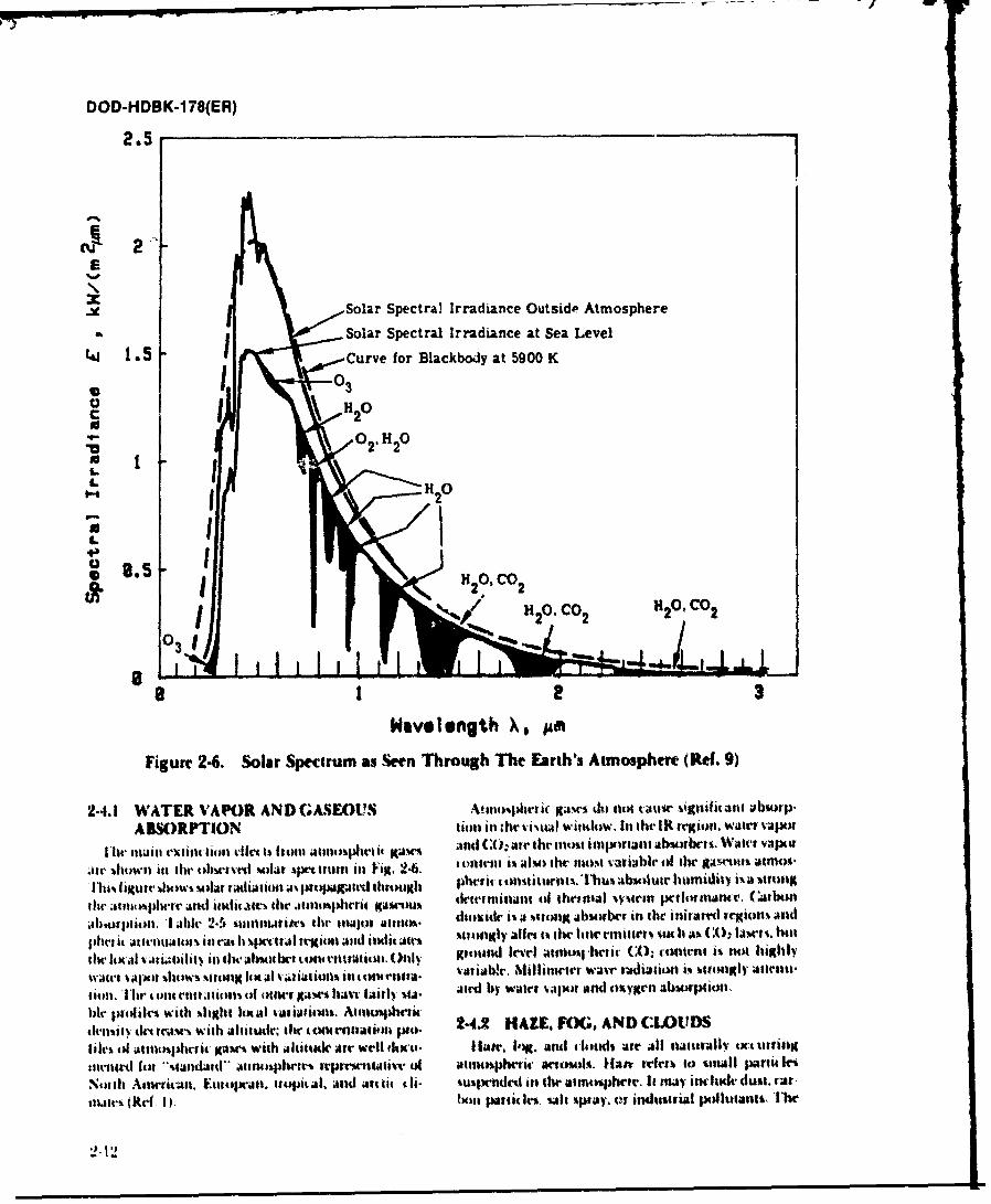
- -~ w
DOD-HDB K-I 78(ER)
E
X Solar Spectral Irradiance Outside Atmosphere
a Solar Spectral Irradiance at Sea Level
4.j1 5 Curve for Blackbody at 5900 K
00
0 1 \ 120C
W. 0 HO
N 25 01 CO 22' 120. CO 2 1120.CO2
103
Wavelength X8 AM~
Figure 24. Solar Spectrum as Seen Through The Earth's Atmosphere (Rdf. 9)
2.4.1 WATER VAPOR AND GASEOUS AtsipfrtitH,~ ga4W% do il nt .allw ~gnattitl ;PbuwrP-ABSORPTION tioti isi ;ht".tu~Al window. In the IR legtion. wair# v.aior
11wl tnilai exuti it l01 t-% hu atfulwr t K~a" and (:0: ate fmost inipurtant ab~of brts. Walet viapur
.)tt showin ith oI bsetved~ %oktt qxtu it) Fig 2.6 4141lit t AIM) the 11140- V-niabi' 0I the AAwn "-lt 11,01
1111% ('MUtV J141WS M40rtd~~iii. ~t~a~t tihtunli 2hef 4t unsrttwomnu. T~Absolute httsiity i'A sittingR
file 31ts, 4wwt ~And ititafth file affpnia t Kaiumy tetrininant of thetmn'al %Yiet Ifthanant'i. (.iArbon.~I~rpain. I~abl 2~an~ii~ tr tf~IjIt ~tttt)idrt, it a tIUIIM abstorbrt in thei' nitared trgio% aid
phei it ativollatis in rai It %Iitital triiu and itlii~t %iogy all" 1% the linermilfti% %lul a%* (,, la .hl
fil it al Va iiiliit$ inl tlmhl4)tr" it)ratiial. ()11II gfolnd level atmnia hruar, (1. content it not hitthly
'w'l't ''~" %hw sI~thron I v~tiAt i011% in ax nna vatiabh'. Nillinwi wavr ra.diationi is %tol attt'nu*aioll.1 l, r itatatioun% o cliter jtw have Ijairl %i alrd by wattet v.tpot and oxygen abnuspuiounWer pI.)ilm with %light kM tal vaiiationt. Aitno%phwtit:tirmihI driC1I with Altituder, WotM(ittt~l i. 24.2 HALE. FOG, AND CLOUIDSfile% (if iatiophetit jpasw with allalidt Air well 1EII14- hiat, Ing. And 1doudKI air all naaartaliv ixtaurin
utiti1rd t -%tandald- ~albsil"r Ptrwilialiv' of Atannphrif arws Ilan, trirs% t i)nalI parlt. fi.Ninth Attirisan. fruttopiria. tiopital. And attti th iii- wUqrdts U) t aitiphetr. It mr&y inclidr dust. rat-at1atr" (kd. Dp. hNin pattiA Imwi ja y, v s itiiiaI tiltants, 'the
"12
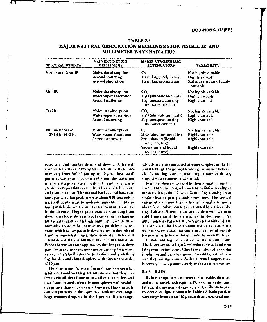
DOD-HDBK-1 78(ER)
TABLE 2.5MAJOR NATURAL OBSCURATION MECHANISMS FOR VISIBLE, IR, AND
MILLIMETER WAVE RADIATION
MAIN EXTINCTION MAJOR ATMOSPHERICSPECTRAL WINDOW MECHANISMS ATTENUATORS VARIABILITY
Visible and Near IR Molecular absorption 02 Not highly variableAerosol scattering Haze, fog, precipitation Highly variableAerosol absorption Haze, fog, precipitation Scales to visibility; highly
variable
Mid IR Molecular absorption CO2 Not highly variableWater vapor absorption H20 (absolute humidity) Highly variableAerosol scattering Fog, precipitation (liq- Highly variable
uid water content)Far IR Molecular absorption CO2 Not highly variable
Water vapor absorption H20 (absolute humidity) Highly variableAerosol scattering Fog, precipitation (liq- Highly variable
uid water content)Millimeter Wave Molecular absorption 02 Not highly variable
35 GHz. 94 GIL' Water Vapor absorption H10 (absolute humidity) Highly variableArosol watleting Precipitation (liquid Highly variable
water content)Snow (rate and liquid Highly variable
water content)
typie. %s. and nurnber dlensity of thtese patlitk% will C:louds are alub conipostl of water droplets ill tile t0.%,;ry with leKlation, Atmosphe'ric acroul partit Ic sites )AM %it' range; the norm'llal Wor~kinlgtdiStiIction bVIweenMay Vary 40111 5X10 ' ur~n kil to 10 JUrn, theVUt' Mlnall t lotd and log is otit 'of total droplet ninber dvn%ityparttavie. u atter atmospherit rtdiatioll. thle m ;stwting (liqluid Witter t-olntnt) ani altitude.inttllfsit % at a Rivet) wavelngth i% tleirrilled by Justtfi- Fogs ar often taltegotil'ti In their foration miet ha-tt' r %1', 4 olitobitiotl (a%5 it al~tt I% itlex tit rt'fit tioll). is. ~A radiation log i'. tooi by taative totilitig (tall-,Ia t till(ti~th ntiltial Nit kj~lotititi base loll. tits it% diew point. Thusk radiAltill fog" tusually tt I ittails piarlt~ le.. Iliat perak inl %itu' at .allow 0,01 Alic. tinlu%- unldter leaf or liartly thtittv tolifiititas. 11wll stlita~ltrial Isolliltan1% ill dfV to nlislevait, humiiti 4 olditions' ete~int of radiationl logs I.- latilitedt, usually itsouitehu- ave n ult* I sages on tile tantet of teths idilit tonttr. ulout 50 tin. Advet iin lt~at lotuted lby vvetit alt ile%-lit tlc he .4-11t. ti ofe litt Isle ilantatmnl. ma tltrilig lrite inig lt ait mt difivitrut Ivetipet.stur . ofivin With wali Illothlee 1*41 tit let I iste pt. iplal vxtitte$ tot iallimnt t.ilet ltonts until thle all 1t',it ho,' tile~ dew lilti Ali
lor VisuaIltadtAatiou it Itt igh littillitv uses (relative Advv. ur lioll at o pt s gtvell visibility will hehtuniiutAxlov So*%). thewe aetosl palt. Iv% 11,1: 11 I- A 11111t seVee talt Kalitst~t thals a w~ataifil higIchtei. whit h I aji, usat I it t %i- i)mow it) tilt- ottir t .h tile. same ts ela Il-itaokimhe lise't thl. dlitI pmt 't uoittewbat Lsigrr thew' actov~ fulfill le% %till Iiegi,.'iin particle silv dtitIIItttuwtns 6I1tvil' III, losgs.aitrourute vt~al radiation inmore titan tltermal itdiatioti. (lruu AMt l14(% at.'du. It-t ' faural ilhiklnalion.,w~hre the teinperalkfr Appuuixt luslte ties.- point. these I ie ,owrt Almblient light 44 %r? tvitu. V% visseal anld twarpatlisa. t Iwdtsto sites% lot allttlsphiera. water 1K s-.vtein 1wltmm v. (lomnl i itr also redist c's %otasvaapor. whit, It lacilitates tile (tnatiior and Kirtwl tit ilmIM14 And 1111'r'y 64kAut' A 'WAshingk 11111- 01 p.-fog drtqalet% and dt ai tisrtapii. wiiit till lifte order si-.r tiltvu l kigdtatttr. At lte itrmal witst iwqa.of loolm. howriier, %ht n. til mtv . lvarly in thvwet iautmtamma'.
Mett cl'intsiou bc'twert fog iand hatte i% witlt Whatarbitrary. (soex working definitions te tr t 14;K" ir. 24.3 RAINlft'r to s'isibililies ud one otcatIwo kilometr r lessIM anti Rainli is asignifi. anit s.utru-vi tlu disie tiriniAl.that "hawe" istittodeu i tnsprs with vimii. Adl WIw waveogith tiOns ealitng" 011 lite. railt-tan girait than oner to two kiloiiittr. f1a tatiusally tAll ate, Ithe inlillstI of1 a tAut 'Al hat' be U If ibert A IeaVV.4 ontain puutiln in the I 'earn it, subvnit sotowr tangi'. numirraw flight as *flows% in 1able 2-6. )aini pa.ii ticFuop contain droplts in the I -ptri to 10-oiam tange. sires range irrim about 100 pam [in ttriue t) sesral inni
DOD-HDBK-178(ER)
in thundcrstorms. They are large enough compared to with heavy wind; loose, dry soil; and little or no vegeta-visible and IR wavelengths that scattering due to rain is tive cover. Airborne dust Gcatters visible, near IR, andrelatively insensitive to wavelength in the visible and thermal radiation. The scattering shows little spectralIR regions. sensitivity in the visible and near IR bands because of
the relatively broad particle size distribution; transmit-TABLE 2-6 tances losses in the termal bands are slightly lower than
RAIN RATE TABLE (Ref. 4) in thle visible and may show some spectral dependence.__________________________________ Blowing dust is not a significant obscurant to nimw
RAIN systems.INTENSITY RAIN RATE
Heavy More than 7.7 mmn per h 25 BT LFEDOSUA T
More than 0.77 min in 6 min The sensor used on the battlefield will have to operate
Moderate 2.5 to 7.7 mmn per h in the presence of battlefield-induced contaminants in0.25 to 0.77 mm in 6 min addition to naturally occurring atmospheric obscur-
ants. These obscurants include countermeasure smokes,Light Less than 2.5 mmn per h vehicle- and munition-generated dust, and fire prod-
Maximumn 0.25 mmn in 6 mim ucts.'The effect of an obscurant oin sensor performancewill depend on the obscurant, the sensor, the environ-
Visile ntiIR atenatin thoug ian iny b ca- mental conditions, and the way it is deployed. Battle-t ilae usnd onl ainuationd trouin m ay biedv c- field obscurants cause extinction, contrast reduction.
bultuin g onitly ainsraead rain r tndesormdiRef LOS interruptions, and an increase in thitter or falsebu0). A t il ete w eengd rain r thunders tr( ef. tr es
an). At mllintern is stlngh ,petin r oil11 rwsatndropBtr.fil- rd c(on taminantis are described qualti-dud he sattrila isstrogly ttpnden onrainrop tativetly in this paragraph. Parameters used for labora-
sin- (list ribut ion. Drittle produces relatively larger toyanti field characterization of smoke effectiveness111111W extintionit coeffic ints (lor a givell rain rate) anti tre eie npr.y6n -7Teefcso eeothe highest boat kscattet ceff it ien's. Surprisingly. thun- loare def in inas. and 7.oTea effctos o metor-derstlo ins have tilt smaller relative 11111w twltil lotgnalitioi and nvioronmretaledfantors. -8 abndrIleif i it-nis with respect to rain rate because of the pre. an2 eeaio n rnsotaetrae9.pas - n
dominance of large drop siates. 29Rainl may also change thle aiarentt target signature 2-5.1 SMOKES AND OBSCURATIONbythanging thec target surfacr ref letance chiaadietis-MAEIL
lt% (lot passive visual w.enots of at live illumainators) AEILanti by ''washing ouit' tile teltptatwme diflel et ill a Smoke mnay be employed ott the battlefield lot boththet mial mene. offensive anti defensiv actions. Smoke has five general
applications onl thle battlefield: obscuration. screening,
2.4 SNOW deception, identifictmion, anti signaling."()bscuration smvoke is smoke employed on or against
S litw i% ,i sigilnal ant alt'rfet lt vssihk. hR. Andi the v'nrmy to derade his vision both within and beyondlIlt1iN Witiiaion. lit the viwilr andl IR icoium 5110W, his kMt-ation. Smoke delivrred ooi anl enem' antitankImilthik ies te anl larjgeit ue4 wavelength. U1 guided mtissile (A U(.N) poosition onlaf pfte the' sys.extantlil door1 tlit) !"ttiw tan be *.cAhed it) % tsibiitl tein Ifrimi acquiring ort sbsquently rmcking target%,ditouh the %now. At high relative hititcl% (>&)!*%) . thereby reducing its electiveness. E~mployment of ob.t~owrVVI. 1ogC tauq fork# witha the %now. In thi tlw. m utation sinoke onl an isniackitg asno"e forte mnay
thetana extuntti in now depnds nott mnl con visibi l- ause it to vary it% spred. inadverttently change its axis ofitS but also tit Ieliillietlut aw ea hmid ity,'a advance, deploy pir.naturtely. anti rely on rwnviskol
1)ataon :mw etusttionand aoinrt in sno0wa~te mean%1I Wf crnmid and control.%crtp limited. Voitinton drIends til %noaw late' and tilt "Screerning smoke is smokec mployed in friendllysniow pallit IV'sadsiuin urnt raodcrs uselrain oorational area% or inl area,% betweiti friendly and4-11114VI'lt %110W lta ki1 '410W WC1i11M (b)A"e Ott enmy fottr% in order to degrade enermy grtound andtc'anfM'#IAtutc-) Ito establish vot'tilos and hmtkUt."tiet aerial obioervation, and defeat t degrade enemry eetio.I orilit irils lotoo (1WRsIC i). t~iu systemus. Screerningt uwk is employed to con.
2.4.5 LOWINGteal grtoutd maneuver. brmahing and tvctvrry oper.24.5 BLWING DVT limu. key assembly aralk and supply routes.
11l0%%ing dust andi sand IA$la bc-comi siglaifit-Al till " Dnxpon stoke is smrm used tstoive he enomyu'ziciutrasmieanerdetyigan.OSincfiation% regarding intentions of U15Army forces. For eaupi,j
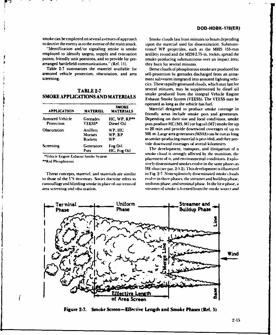
DOD-HDBK-178(ER)
smoke can be employed on several avenues of approach Smoke clouds last from minutes co hours dependingto deceive the enemy as to the avenue of the main attack. upon the material used for dissemination. Submuni-
"Identification and/or signaling smoke is smoke tioned WP projectiles, such as the M825 155-mmemployed to identify targets, supply and evacuation artillery round and the M259 2.75-in, rocket, spread thepoints, friendly unit positions, and to provide for pre- smoke-producing submunitions over an impact area;arranged battlefield communications." (Ref. 11). they burn for several minutes.
Table 2-7 summarizes the materiel available for Dense clouds of phosphorous smoke are produced forarmored vehicle protection, obscuration, and area self-protection by grenades discharged from an arma-screening. ment subnvstem integrated into armored fighting vehi-
cles. 'rhese rapidly generated clouds, which may last for
TABLE 2-7 several minutes, may be supplemented by diesel oilSMOK APPICATONSAND ATERALS smoke produced from the integral Vehicle EngineSMOK APPICATONSANDM TERIJ.S Exhaust Smoke System (VEESS). The VEESS may be
SMOKE operated as long as the vehicle has fuel.APPUATIN MTERIL MTERALSMatericl designed to produce smoke coverage inAPPLCATON MTEREL MTERALS friendly areas include smoke pots and generators.
Armored Vehicle Grenades HC, WP, RPO Depending on their size and local conditions, smokeProtection VEESSO Diesel Oil pots produce HC (M5, Ml) or fog oil (M7) smoke for up
Obscuration Artillery WP. HC to 20 min and provide downwind coverages of up toMortars WP. RP 500 m. U rge area generators (M3A3) can be run as longRockets WP as smoke-producing material is provided, and they pro-
Screening Generators Fog Oil vide downwind coverages of several kilometers.Pots HC. Fog Oil The development, transport. and dissipation of a
*Whicle EiwinrO Exhaust Smoke Systern smoke cloudl is strongly affected by the munition, the**Red Phibhtoi placement of it, and environmental conditions. F.xlplt)-
sively dissemninatedj smokes evolve in the samer phasrs asI] F-dust (see par. 2-5.2). ihis development is illustratedl
Threat concepts. materiel, and mnaterials are similar iin Fig. 2-7. Nonexplosively disseminatedl hmuke t loudsto those of the I' sinvenitory. Soviet doctrine refers it) evolve in three phases: lte Streamer and buildup Phase,camouflage and blinding %nioke in plate of our termsof uiniform phase, and terminal phase. InI (fir lirst phtase aarea 4t reenigand obu ination. 'tatIM411 of -onoke is lor med (tom the sitokt mwuta e and
Ter-ninal ___ ft_ Uifor Streamer and _1
Wind
Figure 2-7. Smoke Scmen-Effrrciivt Lngth and Smoke Phaics (Rd. 5)
2. 15
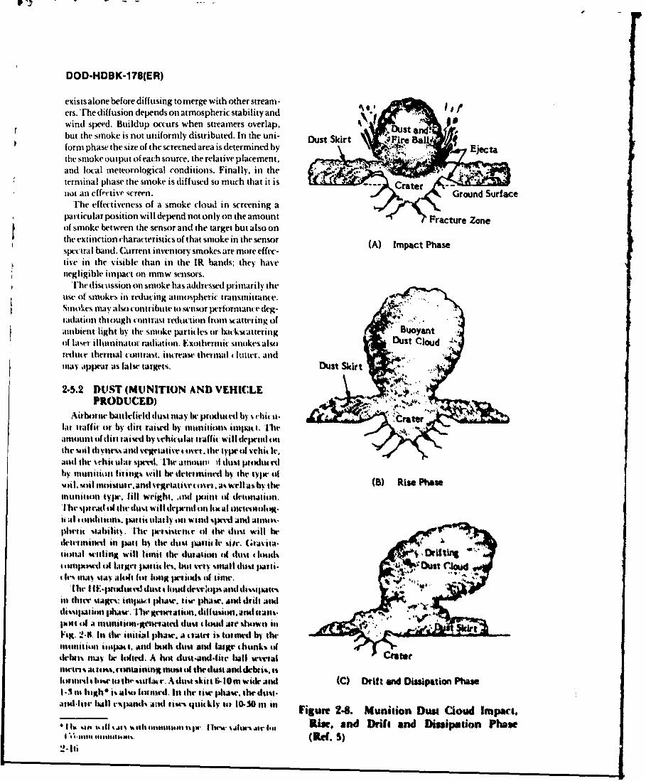
DOD-HDBK-178(ER)
exists alone before diffusing to merge with other stream-ers. Trhe diffusion depends on atmospheric stability and .
wind speed. Buildup occurs when streamers overlap.but the smoke is not uniformly distributed. In the uni- ~ s kr Fr aDustSkir Fir Baform phase the size of the screened area is determined bythe smoke output of each source, the relative placement,and local meteorological conditions. Finally, in theterminal phase the smoke is diffused so much that it is tenot an eff.'ctiv' screen. Ground Surface
T'he effectiveness of a smoke cloud in screening apartictular position will depend not only on the amount Fracture Zoneof smoke between the sensor and the target but also onthe extinction charac teristics of that smoke in the sensor (A) Impact Phasespectral band. Current inventory smokes are more effec-tive in the visible than in the IR bands; they havenegligible impact on mmuw sensors.
The discussion on smoke has addressed primarily theuse of smokes if) reducing atmospheric transmittance. *
5SulokCS ml);Walso contribute to sensor performance (leg-radation thiOughtcontrast reduction from s'attering ofambient light by the smoke particles or backstatteriisg Buoyant(if hast' illtamnillat or radiation. Exothermic smokes also DusJt clouditedw e thermal tcontrast. increase thermal haltter. andimawy lippear as false targets. Duast Skirt
2-5.2 DUS&*T (MUNITION AND VEHICLEPRODUCED) ij 7
Airborner battirfirld dust may be predwuted by svehit t-lat traffi. of by dirt raised by mlunitions iltpat t' Th'leAmount of (lirt raise by %ebiculal ta-affit will depenld ottthe sOl dryness% andi %vweativt ovr, thle type of vvhi4 Ir.
andtheveht tlarsped.Iliramnouta l dt prodtedby nItillnuioa living% will be deitminedI by the type. ofvlil. soil m.),i'AltVre andti eaav oe a% well as by thle (B) Rise Phaseantanutoll typte, fill Weight, .and Ipoint oll deitonation.11W sateatf the Ildust will depenld onl 1w al waoosgit .11 toth Itgorli. tuft~ itlal y on Wind %pe"d 'And At lnthplserat %tability. lar pers.istruse of lte dtlsa will hietiretillnir in par b th dus palmit I' site. Gtaviala-taunal s"ettling Will limnit tile durAtion Wf dut ls 4 DtItII 1111pousad of targert lulli Iis" bt %Ct tria Iwt disa lullti- Ou4 ~ st C40tle Ic% a sltat walof1t hi lng perfiod9 14 litlme.
liar I IF- rawIIwad dit lad eeosad ispteina three stages: itapuOt I abase. tise phAse, AndA uitl and(fijaioa p s.Th gfertin diffusion. and Stan%.ttisi of a rnunititon-grntertand dusto l. loud ater shown in%lag. 24lt In lte initilW Ihayic, a a(iatr is finted by themnlitiont itilapaut. Anad bth ttust a11d fiargi4 ahUnk% oftkiatn ay br loifird. A huo duat-andt.-fite ball suerral CaettrrA aarats. tcanaining nuat ill the darn and debrit. asluattirda lowe tothe %itlata-. A altst %kill &I 10mn widle anti (C) Drift anW Disslpation Phe1-3 tnit igh" I isalo fossed. tit tile tise phras. the dttst.Attallift' lull espalsl% ari usescaiakly t0 10-3Oi in n Figure 24. Munition Dunt Cioud Impact.
1U %10 ~t is oleaaaaes sw 1is slw arI Rise. and D)rift and Dissipation PhaseI suta saaaamaa (Ref. 5)
DOD-HDBK-1 78(ER)
height because of its thermal buoyancy. The large has the highest scattering efficiency (Mie cross sectiondebris settles out quickly. The dust skirt diffuses but about four times the geometric cross section) if thedoes not rise. Finally, the dust cloud, blown by the particle radius is approximately the same as the wave-wind, drifts and dissipates. The dust skirt usually drifts length of the radiation. The scattering efficiency dropsmore slowly than the cloud because wind speed tends to to 2 if the wavelength is much smaller than the particlebe lower near the ground (Ref. 5). size; it drops as (pai-icle Voluime) 2kX4 if the particle size
Airborne dust scatters visible and IR radiation; geir- is much smaller than the wavelength.erally, theextinction is not spectrally dependent because The mas concentration of an obscurant is simply aof the wide distribution of particle sizes. Battlefield measure of the mass of an obscurant in a given volume.vehicular dust may indicate troop movement while An aerosol is the most effective scatterer at a givenobscuring the details of that movement. Vehicular dust wavelength if it is present in high concentration and ifcan sometimes greatly enhance detection of vehicular most of its mass is in particles with a radius approxi-traffic by cuing the target location. However, dust can mately the same as the radiation wavelength.obscure detection and recognition of targets within thedust clouds. Vehicular and HE-generated dust may thus 2-6.2 COMPOSITION, SHAPE, AND INDEXdegrade the performance of EQ sensors and may deny OF REFRACTIONcontinued lock-on of precision guided munitions. rhe effectiveness of an aerosol as an attenuator isMunitions salvos may be used deliberately to blind determined in part by the index of refraction of theartillery observation points. HE-generated fireballs aerosol. Trhe complex index of refraction m(k) of analso introduce visible and thermal clutter. The large, obscurant at wavelength A. may be represented by reallofted debris may obscure the LOS for mmw systems for and imaginary partsseveral seconds; the smaller airborne dust particles donot obscure mmw sensors. rn(A~) = n~k) - in,(X), dimensionless (2-16)
2-5~3 FIRES AND FIRE PRODUCTSwhere
Fireson the battlefield may be deliberately wetor mnay u'tW = real part of the index of refraction.be the result ot burning vehicles or burning vegetation. dimensionlessFire product constituents include burning g;ise and ?.#)= imaginerv part of tile inldex of rf~ratc-carbon particles. 'hewe fire prcitucts may tau~r tram. i-nrnittance losases. scattering, and sensor LOS interrup- ieainestions. Carbon. in partkalar, i% anl excellent aitentialt t'h index of rfraction of an aetols*l is determinedi byof elet'tromagnetic radiation, 'Me illumination fromn ti ops Tio.he eflectiseness o4 al. aercysl as afirem may temporarily blind image intensifir. In the scttere t ieen d~temgiul h elpr
thermial band, fires introduce thermnal tlutit and falwe~ teidxo tfa in Its rftc ist-nmimaan abuntbertargets., Thermial gradient% due to heating b the lite is etcrilinc'c bs the mnagnitude of lte itnaginljt junI oIalso cause turbulente. Firv-induced turbulence inas the irlatlive index.alffect lte img caiyof vitibiv and thrnal % %trms 111V %Iax of a funlti IV will drciltific' It% Vff41 live-ai~d may diffuse radiation from active laser andI inniw ne% a. btoadhanci Attenuiator flit- best bnojdlund
svstells.aitrttiatu' Aft, tainduc ting particles with high asp" I
246 AEROSOL PARAMETERS tltiibowc ihi to (Rf 12).
Blat leficlindw rd tontaininats arc' descibed lt 2-7 BATTLEFIELD-INDUCEDtwo sets of parametc-rs. MbinaerCslTAMrNANTurPARcMefERSin this paragiaph art used as a baseline fix pretlictinig CONAMIAN PARirp efns anddmuETE Raniv
Baitlefi -ld-inducedl ubscuratioa parameters ate used to %PINc ify the amuount of ubwulant III thle bttlr-described in tut. 2.7. field atmnospbc-re and to calculate the iranuniiunr of
radiation thrtlugh the obocurant. iwe ru tiiar24.1 SIZE DISTIBUTION AND m~~am extiflcitit "Iwffsc initt. toncrntration path length
CONCENTRATION producI. viv-id fec sot, and burn rate.
The partile siw distribution of an aerosol is thenumber density or mass cletasaty of Aerosol particles as a 2-7.1 MASS EXTINCTION COEFFICENT
4 1n tiaon Af pati. Ir radius. The patticlec six of an acro. AND CONCENTRATION PATHsot is critical in determining Its sXital if ic.iecy ats a LENGTHscattre as discussed in par.- 2-3. 1. A spheical aerosl 1The mass extinction coefficient *(A) is defincilas
2-17
F '.
DOD-HDBSK-178(ER)
= 4QUthese smokes stay closer to the ground and providea(X) = _> M m2/g (2-17) better protection to ground targets.
where 2-8 METEOROLOGICALa = geometric cross section of particle, M2 PARAMETERSQ =extinction efficiency, dimensionless Meteorological measurements are routinely made atAl =mass of the particle, g. military and civilian weather stations. Hourly records
of meteorological data, taken over a period of severalTrht inner brackets represent an average over solid years, are available for many locations. Standard meteor-angle, and the outr brackets represent an average over ological measurables are defined in par. 2-8. 1. Atmos-the particle mass size distribution. Obscurant mass pheric stability and turbulence -parameters derived
extiction coefficients may exhibit a strong spectra) from meteorological data-are discussed in par. 2-8.2.dependence. The concentration path length prodluct(CI1.) of an obscurant is the amount of obs,:urant c-on- 2-8.1 METEOROLOGICAL MEASURABLEStained in a path of length 1. through an obscurant of Standard meteorological ineasurables include airknIown concentration. F-or nonuniform obscurants dlis- temaperature'. dew point, depression, visibility, atmos-tributed ovet a path from rJ to Y., pheric pressure, wind speed. wind direction, precipita-
I tion. and cloud cover.CL Lcr) dl, g, 111 (2-18) Air temperature is the ground level dry bulb air
temperature. Dew point is the temperature to which awhere giveni parcel of air must be cooled at constant pressure
(:(r) = concentration at point Y. g III. and water vapor c'ontent in order for saturation tooccur; any further tooling results in the formation of
Ttauwmiltante Th(A, through the obst urant is taht It- dew or frost. Dew point depressiotn is the differencelated by between air temperature and dew point. Ground level
r4AJVL ~atmospheric pressure is thve I. rce per unit area p!ve-)= ,I~A( dintensionless. (2- 19) at the ground by the column of air above it. It is reported
in mbar. Visibility is the distance at which it is justPossible to distinguish a high contrast object againstthe ba ckground with the unaided eye. it is usually taken
2-7.2 YIELD FACTOR AND BURN RATE a% the distance over which the 0.4-0.7 turn atmosphericThe 1113%s of obse urant aerosol M:~ dissceninattil by a itansmittance is 0.02. Visibility is estimated by sighting
munition is determined from it) landmarks at known distance%. Relative humidity.eeciuirrd to establish the yield factor of hygroscopic
if '= YI$I./., g (2-20) imokes. is established from air temperature and dewptit.
Where Atmospheric tratassnttatnr at v-3velengths fromM. = itwss f arosol in munition, x ulltraile t tit nmw miay be calculated directly fromk4 = 'f fit r-nV with whit h Artimil is dlissami. nteotologital observable% using standard at-
mttd. ilmninrstioloswritc oeles stich as thoser de-vlopd by the AirV= y irici fa it". dinnsonrs. G.nphWis laboratory teds. I and 13). These
todks reqluire as input the air temperature. pressure.111V yield faclt is Used to account for ihrittowth 44 dew Point or relativt, humidity, and visibility, as well as
liygrose opit Arosol pattit: In in the atmlosphe"r by p~aramters defining the atmospheric~ path geomtry.Absorption to atmospheric water Vapor. Fix these~ At %prceialiaed mmtwuultuical station*. atmosphieritsmuoke-s the vield factor incrases Witlli increasing irls itansmittance has been measured at selerted wave-iis humidity. For If(: smnokes the yield fatc at 10% letgths. Ihle amospheric "itation cefficient at thesrlative humidity is 1.5 and intrase% to 5.5 at 90J% seered wavelentilhs may be drrited directly as shownIrlaitvehumidlity.' Ihyield fact* or wpguf [urmS5 in par. 2-3.3.t0 abtutit Sover the same range. The yield facitor lot fltg ~ SA UYCTGR(oil is 1.0 fRwf. 10). 2 2SAIIYCTG R
11w burn rate, or miast prodlcin rate. of obscurant Pasquill category. tu atmospheric stability category.smoki-s is the rate of delivery of the munition fill msass is it merasure of the rate of vertic-al spread from ant obscuainto the atmosphere. Niunitaunsy with lower burn rates rant aoure-e. The atmosphirte is chatacterited as wse-casually restalt in cooler smokes with less buoyant rise; bit (Pasquill Citegori-A and B). neural (Clod 0). or2-1l8
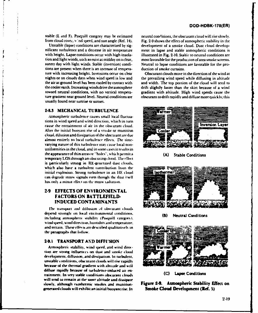
DOD-HDBK-178(ER)
stable (E and F). Pasquill category may be estimated neutral conrhtions, the obscurant cloud will rise slowly.from cloud covei1, %k 1nd speed, and sun angle (Ref. 14). Fig. 2-9 shows the effect of atmospheric stability in the
Unstable (lapse) conditions are characterized by sig- development of a smoke cloud. Dust cloud develop-nificant turbulence and a decrease in air temperature ment in lapse and stable atmospheric conditions isrwith height. Lapse conditions occur with high insola- illustrated in Fig. 2- 10. Stable to neutral conditions aretion and light winds, such as exist at midday on a clear, most favorable for the production of area smoke screens.sunny day with light winds. Stable (inversion) condi- Neutral to lapse conditions are favorable for the pro-tions are present when there is an increase of tempera- duction of smoke curtains.ture with increasing height. Inversions occur on clear Obscurant clouds move in the direction of the wind atnights or on cloudy days when wind speed is low and the prevailing wind speed while diffusing in altitudethe air at ground level has been cooled by contact with and width. The top portion of the cloud will tend tothe cooler earth. Increasing winds drive the atmosphere drift slightly faster than the skirt because of a windtoward neutral conditions, with no vertical tempera- gradient with altitude. High wind speeds cause theture gradiient near ground level. Neutral conditions are obscurant to drif t rapidly and diffuse more quic kly; thisusually found near sunrise or sunset.
2-8.3 MECHANICAL TURBULENCEAtmospheric turbulence causes small local fluctua--_______
tions in wind speed and wind direction, which in turn-cause the entrainment of air in the obscurant clouid. Inversion LayeAfter the initial buoyant rise of a smotke or munitioncloud, dilution and dissipation of the obscurant are duealmost entirely to lcal turbulence effects. The time-varying nature of this tturbulentv may' c~iue Ilocal non-
uniformities in the cloud. and i ttetae trslsithe appearance ofthin areas or "~holes". whith 1wriit a (A) Stable Conditionstemporary LOS throuth an ob ur ingt lud," Thee tis particularly strong in HE-getterated dust cloudls.initial explosito. Strong tutbulence in an I IE t loud I~.ma ~can degradeitita o ignals even thouigh the dlust *-Wilhas% onl) a mnor if 's a In (tth ntw 1111adiatton,
2-9 EFFECTrSOF ENVIRON.NENTALFACTORS ON BATTLEFIELD-INDUCIED CONTAMINANTS
dr~tend stronglyv on bucal cenvitont-tital cooontlan. ()NurlCniiniwdig atmiosiphrt stability tPasuaull targoty..() NurlCnii
wind %spend. Wind (i443,4t4111. hunlidto and twnprtamr,and terrain. f'liew ele~t t are de tibmd qualitatisels int- -
the poaagraphs that foallow.
2-9.1 TRANSPORT AND DIFFUSIONAtmiospheric ittability, wind speed, andl wind ditm's
tion air strongt influctuws on dtost and %imoke tlnuddevelopment. dillustion. and dissipation. In turbulent.unstable mnoclitions, obsuiat t inds will rise rapidlybec-auw of the thermal gradient with altitadvatul willdiffuse rapidly because of itirluletur-induced air en-(C Las aiintainment. In v'ery stable conditions olbacwant &bns C L"eodiinwill tend to remain at tlw sano altitude and dissipateslowly. althouglh mothitnic smokes and munition. Figure 2.9. Atmospheric Stability Effect on
piwraed lodswill exchibit an initial buoyant rise. In smoke aoad Deveopmnt (Ref. 5)
2-19
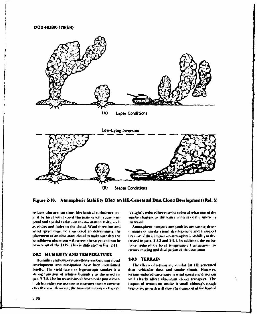
DOD-HDBK-178(ER)
(A) Lapse Conditions
Low-Lying Inversion
() Stable Conditions
Figure 2-10. Atmospheric Stability [fect on HE-Cenentaed DustaCoud Development (Ref.
ttedut " tob~cutatim time. Met han,ia tutbtaknr t rr . ~ii~thIdv ttu~ rtlbaia hr index~ ofotitison Wf theatrdl by lotaul wintd %.xrdt fluc'watitmn will gauir irtn- %mnke changri a% the' watt tontrnt ol the catkr isjn)#dI andr %5)atal vatiItti% in 061 tuant tlrtt.ity, . t h iiMII.a% .'ckt' iand Itolew in the 4lod. Wind diinion anti Aiaaohrtit temperature inoldvi re tr onot detr.wind ;p"c~ miust be rcansadrd in drotitnting the tinant%)I o1 '.n-A4r t1)11 iod tkuipnnt and tranyi iuplacemnt tl an Muicant cloud to miake %utrh thi h ln b~r tit thti-. iti4Ja t on atfl)i.l14mic %tatility a% di.windblown obu tatant will 'umn n arget anti not he t u%%ed in pan'. 2-8.2 and 2-9. 1. In addition. the turboa.blown out olth uI 1O. This i%. inditaau'd in Filt. 2-li1 Inr indlkVc'tibw lota temprture fluttatita. in.
4taw'. inixing and di'.'ipation uS the otnrucni.9-.2 HVMIDIT AND TEMPF.RATIRE
IHwnidiiren m prarar fcnobiwAnt cioWc 1-9.3 TERRAINdt-Mopnrnt and cliitipaion havi' k... mntned '1tn df'irt1 of terain Air witnilar lot iE-groeriatedwirly I'.IWm 'irid l1"u114 of hyglOWmopi rnOkM' i'. A dus.t, vchit-ulat dumt and '.mtkr clud%. tioort.
'.emOng ontun oil rlauivei humaidity as. diu u'..id. in tmrain-indwrd variation'. in wand '.prcd and ditecioju, 2-7.2. lli~r'.d.eour'aoqtar.n will clearly affect bwcawaa cloud itacaspuui ibm'v11 J1I humidaity rnrnmunat% incte"M Oir "Afiuri tiut a of terrin 4n ,hinur is unmal although woughrun aaritem'. I tovir. thwaa.. e icin:cu~ toii trot %vrtaivir growth will %low ibh' tranrprw t the Ibaw ol
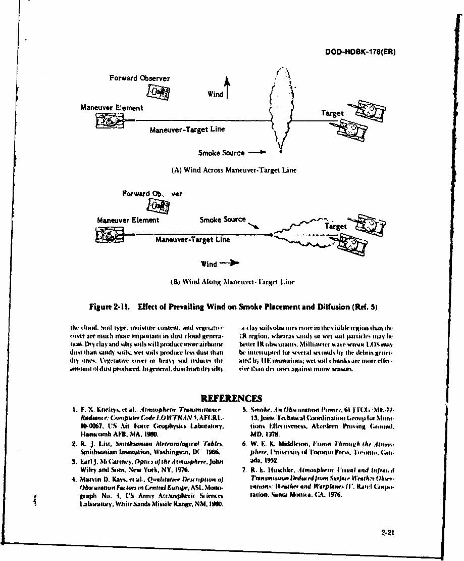
DOD-HDBK-178(ER)
Forward Observer 4
Maneuver Element WindtTre
Maneuver-Target Line
Smoke Source -
(A) Wind Across Maneuver-Target Line
Forward Ob.. ver
Maneuver Element Smoke Source .-.
Mul - Maneuver-Target Line
Wind*
(B) Win~d Altuig.%lanwivvr. I 'rgrt Latw
Figure 2-11. Effect of Prevailing Wind on Smoke Placement and Diffusion (Ref. 5)
CIVrs Are Mth wwyet imtxman. in 4uoo cloud Menrta. ;R tr~iutt. WlinrA* U# w tM rl14 P41sidr may h.elitin. 1)'yla ;and %ilty vihswill latuwrtnturait~biw betlet IR t~b&utatu;o. Midlittite ua~'vr I .U"imi thian %indwt i%; %vt wvilt Wdtk-r lc%% ino thant be ttlptim lilt Wwfa tia)mlk h) teht'% Iclicnt.
ahmcNnin tA duot prtMllwt. In Xtva. dus~t farom duh fie th~~ian dt t*m. altaino114" mrnu*
REFERENCES
1. V. X Klneia%,rt al'. 44 imwoph~er Trimaadn'e S. SmokAn ttoagtton Priecv. fl j1X ItF7.ft~d~nu (.elt~aIer :f 10 'Tr.4xf1* ARI .* 13. Joini rI hnitall (uvinii Go oup u Nun,
W-O06. U'S Air Form (eupbyii. t~ahutoy. wmb Mittiwrs. Atrt.Inm PruVianjt (4404mnd.Itaniomb All. MA. 19M0. MD. 1178.
2. ft. J. Ust. 8muahlrnaa Alrevoralogut-al r'AbIei. 6. W. E,. K~. Middleton. Vajeon Through thy .41mm.%onihuntan lastiutiton. Wathinstien. DC 1966& ph're. Uiwritv u4 lueati tr Caon;.n.
3. Earl J. NkCarmn"j. Optirsoth Ajt 4mosphre. John ad&. 19%2.Wiliq and ta% New York. NY. 1976. 7. R. L.. Ituwike. .4tnnphrrit inaaaI anif Iitat.d
4. Marvin D. Kay%. et at. Qsuaetalow~ 1k.r.ropito o Thonsnaato IMrwr imnn Surf ~ace tlrag- )bsor.()buau a tto cui n centra E. urope. &M.Mnui. ationsi: It'eAev and Warplanes ItIt Knd (Atixt.
grpaph No). 4. V'S Ainoy Amrumpheti Sti icm ration. S~ns Monica. (Lt. 1976.Ltkutuacy. %'hitr.Sands Missile kangi. NM. 1960.
2-21
DOD-HDBK-178(ER)
8. Fre.ierick Gebhardt. Dei'elopmient of Turbulence 12. Gerald C. Hoist and janon F. Embury, DesignEffects Mlodels, Science Applications. Inc., Ann Criteria for Smokes and oJbscuran is, ARCSL-[R-Arbor, MI. 1980. 82024, US Army Chemical Systems Laboratory,
9. Williamn Wolfe and George Zissis, Eds., The Alberdeen Proving Ground. MD, 1982.
Infvcru'd Handbook, Environmental Research In- 13. H. J. P. Smith, et al., FASCODE-Fast Airnos-stitute of Michigan, Anni Arbor, Mi. 1978. pliea Signature Code (Spectral Transmitilance
10. Louis D. Duncan, et al., FOSAFI. 82. ASL-TR- aind Radiance), LIS Air Force Geophysics Labora-
0122. UTS Arm%. Atmospheric Sciences Laboratory, tory, Hanscomb AFB, MA, 1978.
White Sands Mlissile Range, NM. 1982. 14. D. Bruce Turner. "A Diffusion Model lor an IUrban
11. l'RADOC Pamphlet 525i-3. i.-JnpovineI of Smke Area". Journal of Applied %leteomlogy. 83-911980. (February 1964).
BIBLIOGRAPHYVisible and Near-IR Systems Optical Propagation and Scattering
Elet tro-ophi(.% Handbook, RC.A (',aniotjtion. I.anca%' Max Born and Emil Wolf, Prinacies of Optics, Pet -
ir. PA. 1974. ganioi Press, Oxford. Great Britain. 1975.I., P. Obert, J. T. WmxlI. and C. J. Nash, I'asonlr.% F. X. Knvitvs, et al., Aitmospheric Traissnltance
hdad book of FE) Sensor 1Prylormauace. I'luppie I Radweece Corn puler Code 1.0 WTRA4,V 5, AFGL'1.Vatuvaul European. Enirone~aie W). US Atmtv 'R-100067. US Air Forte (etphysits Laboratory,Night Vitsion ;Anti Elet tro'flptit 14abotatoti . Fort I lanst onh AFB. MA. 1980.Ilhtit. V'A. 1981 ('1115I D(:U1'NIS IASSI. Carl J. \It(4ittntr\, Opt..t of thec Atmjosphere, JohnFlED) CONFID)ENIAL). WiIVV 10111111. New York. NY. 1976.
Infrared System V. I. Tatarski, The 1feri al the Titrbulen.4 IttmosphereChrisAtqdtel Duew and Laten Peterson, OPb'e41' oni Wgiaa, Propegatioti, Wrt Progrant (of St irItifit
~~~~~~~~~~~Fj1 Twina,..~ ~su. nutat ytn~ a~' lrmsatitina. Jettuslet. Wrtel 1971.tonsnental Krwar. h Irwtiotte MlNit Iigani. Anlti ObitriuantsAttior, %I. 1982. tlui% D). Dunmn. et al.. OSAI. 92, ASL-iR,0122.
j. -M. Ijoyd. Thrtal Ittlegx Xy.%temns, Plellumn irh I'S AtmV Atnuspherit rwir Labwatory, WhiteNew Y104k. NY. 1975, Swtnd iShsile Range. N.M. 198Z.
L,. P, Ohni, J, 1'. wimd. and C. J. X41 ,ob. I 'its CrtarI C. 1lu a.nd Jaanim F. Etnbwy, DrAlige C,,erristhandbook of W) X'w'nzvm i'etjornteuitr, f'olisame I fur ,Smnkes and Obititrwtits, ARCUSL-TR.$20U, VSI ,altaal f, nvvpvmn boiroomvenii i ). US Attiq Arnis (hentis al Sysscmi tabuaturl. Aberden Piuv-N111ht Viin 'end vk4eit-Olp~ts .. 'talts. trol. ing (wund, MW) 19n,2Iks~tir. VA. 1901 Ii11lS IDs(W.UNIFNlA 15 A%* 'Markin W) K rl al .i Qaiebateei' IWsrapfttv 0 o b.FHEl (CONVHDEN'I1Al.). U 140vnnorn Fitt foA in Centrol Eu.rope. ASI. Moetti-
J. A. Pathm.rs -oiaiit Pedtiitrn t *.il heral lnig-t' gahN.I ~iyAtnpei r'nslbring Svttrn%-. Opt.. alotiouginh t 15. S2% (19761, Au) Wh~t tsMsile %01d ange. NM. 19,40
WWia Wolla'tu GnnS t.orr bia. F~AI.. The Infrrd .arnetrd I'ubtleery flalleftadd Condaeon"s, Th I Crhon-ilandbiulk. kc~unwtil viwafk It Instituir *l ta t snoinatitm (rip joint A. titn (.nioup tJAG;)M~di 4 ian. Anti Arbipt. Mi. 1979, 10. 190$.
MlIUM1wv Waft SyStemst 8"lrnk?. .411 0bsretj 1rfmr 65 Ji'(( ME.7.3.K. J. 5tandi, vi a).. Milhheetrr l~i'tt' Nw mAie and Corti.. Joint Tchn: Al 0** inaiion ('*oup Munition
pottrnb,.ARCSI(~l0S 1Il K.'van h 1noiiv. LIU:,a. firovu Abe~rnv Pnrsing (;round. MbD. 1978&(In~ago, 3963. ItAD0C P'amphlet S25.1. Ef'p .vrn~n of Swoke.
1980.
2-V2
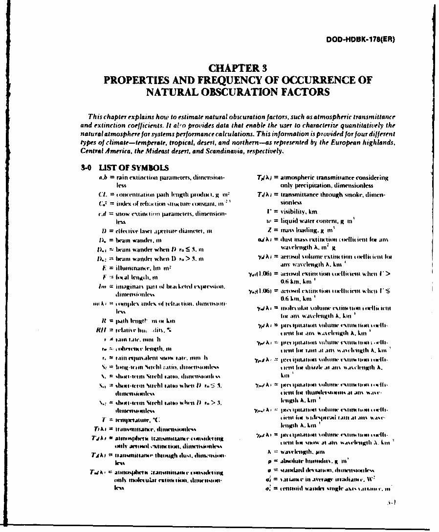
DOD-HDBK-178(ER)
CHAPTER 3PROPERTIES AND FREQUENCY OF OCCURRENCE OF
NATURAL OBSCURATION FACTORS
This chapter explains how to estimate natural obscuration factors, such as atmospheric transmittanceand extinction coefficients. It also provides data that enable the userT to characterize quantitatively thenatural atmosphere for systems performance calculations. This information is provided for four differenttypes of climate-temperate, tropical, desert, and northern-os represented by the European highlands.Central America, the Mideast desert, and Scandinavia, respectively.
3-0 UST OF SYMBOLSa.b = ruin extitiios panhitamiters, diturivtin TdAW = atmospheriic transmittance considering
lessonly preciittion. dimenisionless
(J. = t oiwenttioi patsh lcigilt piotAti I. X ns T4A) transittance~ through %'iioke. dimn-(. = index ti4 rvfniw tion stltk lure tmtsiit. t , ~ situlk"
vd=snow extinit timoi p~tointv. dinwitson- V = visibility. km nICU Uit = liquid waster cotent. Xil
rife=tfintve lawr alwpiiw ttsllie. Ini Z = tnii'~s lottling. It ilIi
1.= bruin WandeI. mi 04N) = dtulsllavhJ etitliotti (Ieffit ielit Itr atit
=. brait waunder wheun 1) ro S A.ti watvirtigth Ank
D).,.- brain waitttt whtit 1) va > 1.i %1A) ar-'l 'Volustt VX611tst liti'l fi6 itII t )$tllw~nj~rlii 411v~ wwrtinnitth A. kill'
lest~-.006 ji tcWl~t ov Ot iib) et~sim ti tr trt ui whltitl I
us.~~~~~~~~~~~~~~~~~~rii A' uirmitiulit tl~i11)1 ~iiuitstv1 nst iti i miu it-tit£ wli I' S
It = :)mill Irligi?' tit m4 kill~ .:
Hit forlali~r k.iti. it isnlit *1iA W.; i t 1t il A. k l s
'histilt list %iArbl .1i1s stanstt.sdt LiiihltlA.Llgi~ lialeti~iu; i % mm fw itlis Is 1 Ier p ii t ipsuim %4*141tsir v~tiluilt milrl.
1%1410 4illii 'WrIl ';'fil eiI lit-it II. dtio-ir ta isIighA
TiA u t a ns I~trh tio wssitr 1)111tl A. List
A oa ian~mitur ihisisssh Ijisil dsmsiiisain wairili. juit
k-%% 0 .abniuhutr I11tauW14it. It fit'
41111% 1"Pinult "tilklits0l =1"oil do %.I$iu iianu akJ ill aragII ilu .
d4 irIfisi wasl" %oig~ra s %a I
DOD-HDBK-1 76(ER)
3-1 INTRODUCTION atmosphere molecular transm~ittance term T.(A), theThis chapter provides quantitative data on natural atmospheric aerosol transmittance term T.(A) or
atmospheric extinct ion to enable the user to character. atmospheric precipitation transmittance term T,,(X),ize this atmosphere for systems performance calcula- and the dust transmittance term TM(k) or smoke trans-tionis. It also gives weather data for four different tye mittance term"FT4A). In the absence of precipitationof clitnate-temperate. tropical, desert, and northern. TX wAT().XT() 31Par. 3-2 is designed to provide atmospheric data for TX ~,AT(),XT() 31user-specilied weather conditions. It contains tables dimensionlessand equations dcsigned for use in the c.alculation of whereatmospheric extinction by water vapor and other gase- )A Wa~elt'llillth pmIous molecules. and aerosol extinction due to hate, fog. TA ttopei rnmtac osdrnclouds, rain, snow. or blowing dust. Data ite provided tiilv inlel tilat extinc tion,. dimension-for the visible (OA-O.7pm) and near ialtared (IR) (0.7-
lnij spectral bands. the thrma.-l bands (3-5 and 8-es12pmi). thle Nd: YAG I ,06pm) and C .01((10.591pin) laser 011AJtmvriowetim ns ittnensioeringlines, and at 35 GHt and N- Wilt ,nillizneter wave )i eo, xnc ,tnsors'ttlw) frequencies. lt iaismittame thtotigh smoke, dinti.
Fuir types of climate are dest-ribed briefly in par. 3-3: ioilessA tem1periAll region. lept-1011ied by the Central EurtOpe-an I4 I aIi la tiit I-t tit olict dustI. d IsI vnion.
highlands: a tropital tlinaate. represeted by Cenital IvwsAmeria. a deseritha~ite. tepresentied bv the Mideast
deseit iegioo; and a high-latituide northern thinate. lIai 1%aui 1.111a% 10au %it M.
represented by 'ptr Sadnai.T e t ifit loc alesweir weitedt both because tf the rangeoW weathtr types. T(A)=TA),(A)~AT4) 32chi-v ins lotde and Imt sw of th'e Avoilh~ililcy) of uple. (iIi tt1Vtljolessreliable cwinrottloit'al iiiturd*. PZ41, 3-3 Also tonia mseAsonal avrage ct'tilcNoital tw'csaatiot1% for 4heWlot atiocts, designed to lamilistise thr engicet with the 1AA Itttb5hia ra~acaaae thdc%trty iii weather tondition% in whith a %potem &%icnnItl atIbcatic.icceaa~kiwill haV to ot-trate.
Nwr tk-tailed infornatcan abotlf theV IceqtIen 0fI1hr sn sni.TA 10tKarrnso tuurml 41 trlwati foc ibm-se lt,) =Loitit 1% as cIi Ke' in pans. S-4 thrnctgh 3.7. t drtaik' Iths s odst A =10ino. tuation will gasi the rngincri a I ltracein ate t34their I% Iof wraithe, under whit ht wo sat-n mis tpetate hi t h4'PtI 4 haIM letiji tiam ttawii throcigh iti
atn te rlasv veuc-r~of bcse c.cidtcnsIllitta- 04tital attn vpb-r, whit ,it% luck-s pm-qaccion andIions. of the Ivn a Ison inl a , it nci IalusaittAntV air blottinglp slsist. '11e infccniation ini Chapltr I ciM
lii lusk tw c-pi- caatas-Eurp%"r and.\ iM~l 141 oa. ItansMratn t7alt tilatanni ltrough 1341lehU lcIi*:su1a00% in 0l04% mowats Ireqac-nes $8 atIMMspbrcc tittlitibtiR 4111W16WMM higth (x~~'s IMEtaatscnetiatki in the tcisible. thwrcwnal. aMii mmw irt' - gm-i-ateddumtdltus taise lIn .rhlculam stalh. and ivec
Vatair tabitlaacd tn this% thapart fot the %wubk
3-2 OPTICAL PROPERTIES OF 10'47mm) tw IR (0.7-1.1Ipm). and thrtnwl spnitalNATVR L OACVRAnONband% 13-5prn atr4 8-' 1 .acn a% we-ll a,, ltr diwtir war-
NACTRLS C T N Irlhs at the 1.060M INd-YM,' Lmne) and I0.SWI ramiFACTORS((A).- laws laser litwes, and the 35 ('14* aloe. 94 GUi.
M e tabIe ar-d equaiatss% in this Intaittaph air tiiid tocnr lit"u-. When ung y-alta- Itiin dillrmt %ubpara-augma n al"listatnsospbrni itrat.smittancthtiniqth graph. IM cnokrlal 0VspjAi..i and sWAaItrini. INmthe tutural atnnsArirwo sasrr-s4wrcdi wrather itww engines- musit mak e them u tagialu iuwditilot. Pat. 3-.1 I teats motllvulac Awb'c~ 4nirw mn sat - usedttaktulalts-r. Itaa imtnecltn air 4 "Mmi$.trnictil the th-a; natural atanupher. Addituonal bk-. Foe icsaran-. rain shoul .siut uii~ a, epit iantsenamn r lift"-sdtarto acmuspbwic .anil abstwp. toes abuse hrerring: it will 1W aiiwtaiard in- hightitai andt miatrn. rait. snww and blowinx dut ass- trlact htmidit and limitd %ibi'itl.oactn sitti pass.. 3-02. tharaugh S-3.. 11w quatiwis in cIS paragraph nsav ts-uite acun-
Ihe ional aiti-ps~hnits itaiunittane 71h) lot a itv us-rhio amngf titaiiii hacriditV. absir hrtidity.lulls Ienith (range so tretis the )NIntM tA f the s:AI ansi dew- ixant. sk-p-ntme can the data asailabi to the
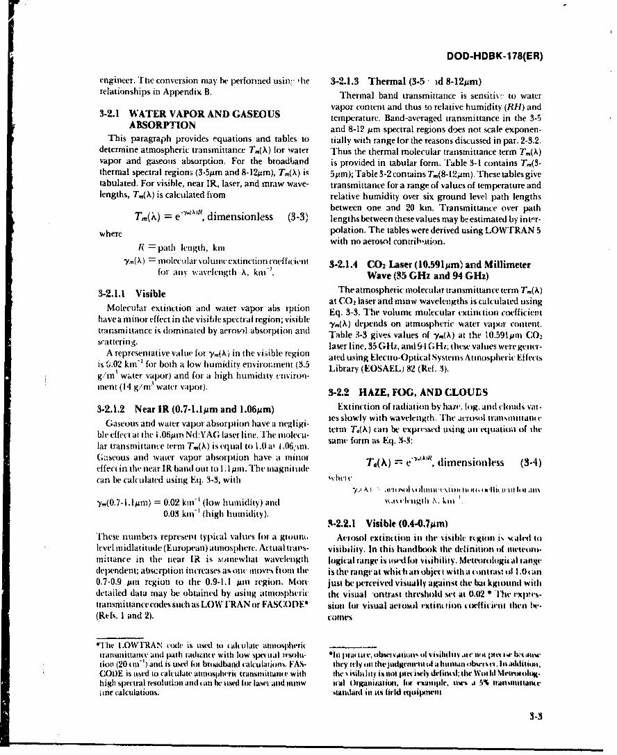
DOD-HDB3K-178(ER)
engineer. 'rhe conversion may be performed usin,,. 'he 3-2.1.3 Thermal (3-5 - d 8-12,um)relationships in Appendix B. Thermal band transmittance is sensiti%, to water
vapor content and thus to relative humidity (RI-) and3-2.1 WATER VAPOR AND GASEOUS temperature. Band-averaged transmittance in the 3-5
ABSORPTION and 8-12 prm spectral regions does not scale exponen-This paragraph provides equations and tables to tially with range for the reasons discussed in par. 2-3.2.
determine atmospheric transmittance Tm(X) for water Thus the thermal molecular transmittance term Tm(X)vapor and gaseous absorption. For the broadband is provided in tabular form. Table 3-1 contains Tm( 3 -thermal spectral regiom (3-5tpin and 8-1 2;m), Tm(X) is 51Am); Table 3-2 contains Tm(8. 12Mm). These tables givetabulated. For visible, near IR, laser, and mraw wave- transmittance for a range of values of temperature andlengths, Tm(X) is calculated from relative humidity over six ground level path lengths
-- Y.(A)1?between one and 20 kmn. Transmittance over pathT()=eY()~ dimensionless (3-3)1 lengths between these values may be estimated by inter-
where polation. The tables were derived using LOWTRAN 5
RI = path length, kmi with no aerosol contribAtion.
-Y.( X) = mloleckilar volune extiniction -oe ffic-ien t 3-2.1.4 C0 2 Laser (10.591Aj~m) and Millimeterfor any vwavelength X, kill"'. Wave (35 GHz and 94 GHz)
3-2.1.1 Visible The atmospheric molecular transmittance term T,,( A)
Moleula extncton nd wtervapr ab rpion at C0 2 laser and minw wavelengths is calculated usingMleua nr eftictin and wt~e vapr a bs reio inl Eq. 3-3. The volume molecular extinution coefficierit
havea mnoreffct n te vsibl spctrl rgio; vsibe V('\) depends on atmospheric water vapor content.transmittance is dominated by aerosol absorption and Table 3-3 gives values of -y.(A) at the 10.591pmn CO 2scattering, laser line, 35GHi, and 9-1 CGui; these valu tes were get er-
A representative value for m()in the visible region ated using Electro-Optical Systems Atmospheric Effectsis 0.02 km-' for both a low humidity enviroment (3.5 Liry ES L 8(Rf3)g/ m3 water vap~or) and for a high humidity environ-meent (14 g/m' water vapor). 3-2.2 HAZE, FOG, AND CLOUES
3-2.1.2 Near IR (0.7-1.lpum and lO6;Am) Extinction of radiation by hair, tog, and clouds vair-
Gaseous and water vapor absorption have a negligi. tes slowly with wavelength.T'he acrouol itansmittant
ble effect at the i .O6prtn Nd:Y'AC laser line. The iniloltu- term T.(.A) can be expricssed using an equatio.) of thle
lar transmittance term Tm(X) is equai~l to 1.0 at 1.06 :'ini. same form as Eq. 3-3:
6.4seous and water vapor absorption have at 11minoriesones 34effect in the near IR band out to 1.1 ipm. The magnitude ~ ( ~~dresol~ 34can be calculated using Eq. 3-3, with Wvt
,Ivm4 1 .- t k 1%t itillict\1m it I l, i K-111 it-lit t of dIN
,Y.(O.7 -I. 1pm) =0.02 kil- '(low humidity) and % axctlvogill Nt~. k ill
0.03kin-(hi h hu idit). -2.2.1 Visible (0.4-O.7iM m )T1hese numbers represent typical values fot at growit, Aerosol extiiCtiott in thet visible rvgiomt i, Milaled tolevel miidlatitude (Europeani)atmnosl)here-. Actual travs- visibility, In this hsandbook thet dtelinitioti of tneteoro-1in*ttance in the itear IR is somnewhat wavelength logical range istused tot visibility. klelteurtiltgitalrangevdependent; abscrption increases as ontc moves fim the is the range at which an objet witht a. ontrast ot I.0 can0.7-0.9 pmr region to thie 0.9-1.1 pAm region. Mot- just be perceived visually against tile bit kgtound will%detailed data may be obtained by asing atmospheric the visual ontrast threshold set at 0.02 "T'he exm,1transmittancecodes such as LOW1'RAN or FASC()DE 0 sion [or visual aerosol rXtit Iioti coellit irmt thel lor.(Refs. I and 2). ~tW
l''lic tOWT1RAN code is used to cakimlate atmosilherictransmnittanice and path radiance with low spem tat tesolti- "In jra tu., £ubsematiav Wf visitulityat A i I61 u)Iv i dwimW
nion (20 cm I) and is used fi broadband calculations. FAS- they ifly on the jugewinm t l a huminan nb~.r~se, lIt addititti,COOE is tsed to calculate atmiosphrric transmittante with tile % ilibility is notu ptcisely defined:l tile Witt 11 %tevololivg.highi spectral resoluitian and tani be used for lasce and1( imw icvtl tOrgamitatiwu fot, ruicamipk. uss 1, 4% Itanmittaturi ne calculations. stanidardl in s% field equipmnt
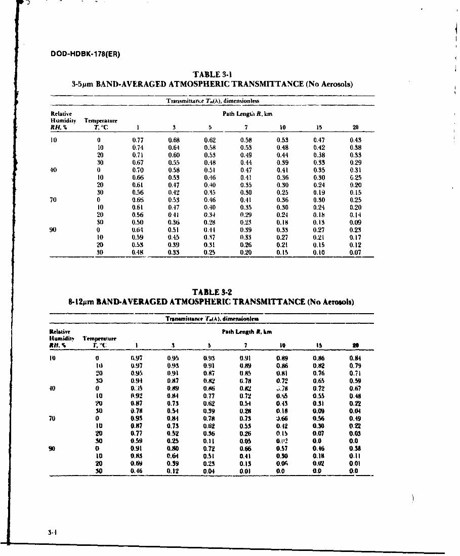
DOD-HDBK-178(ER)
TABLE 3-13-5pm BAND-AVERAGED ATMOSPHERIC TRANSMITTANCE (No Aerosols)
Transmittance T,(,), dimensionless
Relative Path Lengthi R, kmHumidity TemperatureRH, % T, 0 C I 3 5 7 10 15 20
10 0 0.77 0.68 0.62 0.58 0.53 0.47 0.4310 0.74 0.64 0.58 0.53 0.48 0.42 0.3820 0.71 0.60 0.53 0.49 0.44 0.38 0.3330 0.67 0.55 0.48 0.44 0.39 0.33 0.29
40 0 0.70 0.58 0.51 0.47 0.41 0.35 0.3110 0.66 0.53 0A6 0.41 0.36 0.30 0.2520 0.61 0.47 0.40 0.35 0.30 0.24 0.2030 0.56 0.42 0.35 0.30 0.25 0.19 0.15
70 0 0.66 0.53 0.46 0,41 0.36 0.30 0.2510 0.61 0.47 0.40 0.35 0.30 0.24 0.2020 0.56 041 0.34 0.29 0.24 0.18 0.1430 0.50 0.36 0.28 0.23 0.18 0.13 0.09
90 0 0.64 0.51 0.44 0.39 0.33 0.27 0.2310 0,59 0.45 0.37 0.33 0.27 0.21 0.1720 0.53 0,39 0.31 0.26 0.21 0.15 0.1230 0.48 0.33 0.25 0.20 0.15 0.10 0.07
TABLE 3-28-12,sm BAND-AVERAGED ATMOSPHERIC TRANSMITTANCE (No Aerosols)
Tnummistane T4(A. dimermionl'
Relative Path Length A. kmHumidli" TempreatueBit. % T. "(, I A 5 7 10 is g
10 0 (1.97 0,95 0.93 0,91 0.89 0,86 0.84I) 0.97 0,93 0.91 0.89 0,86 0.82 0.7920 0.95 0.91 0.87 0,85 0.81 0.76 0.7130 0.94 0.87 0.82 0.68 0.72 0.65 0,59
-10 0 0.J)5 0.9 0.86 0.8 .P 7 0.72 0.6730 1.92 084 0.77 0.72 O.is 0.55 0.482 0.87 0,73 0,2 0.54 0.43 013 0.2230 0.78 0.54 0.39 0.2S 0.18 0.09 004
70 0 0.93 0.84 0.78 073 ;).66 0.. 0.4930 0.87 0.73 0.62 0.53 0.42 0.30 0.2220 0,77 0.52 0.16 0.26 0AS 0.07 0.03s0 0,59 0.25 0.11 0,05 0,twl 0.0 0.0
90 0 0.91 0.80 0.72 0.66 0.57 0.46 0.38I0 0,A 0.64 0.51 0.41 0.30 0,38 0.1120 0.69 0.39 0.23 0.3 0.06 002 0.01s0 0.46 0.12 0.04 001 0.0 0.0 0.0
!.
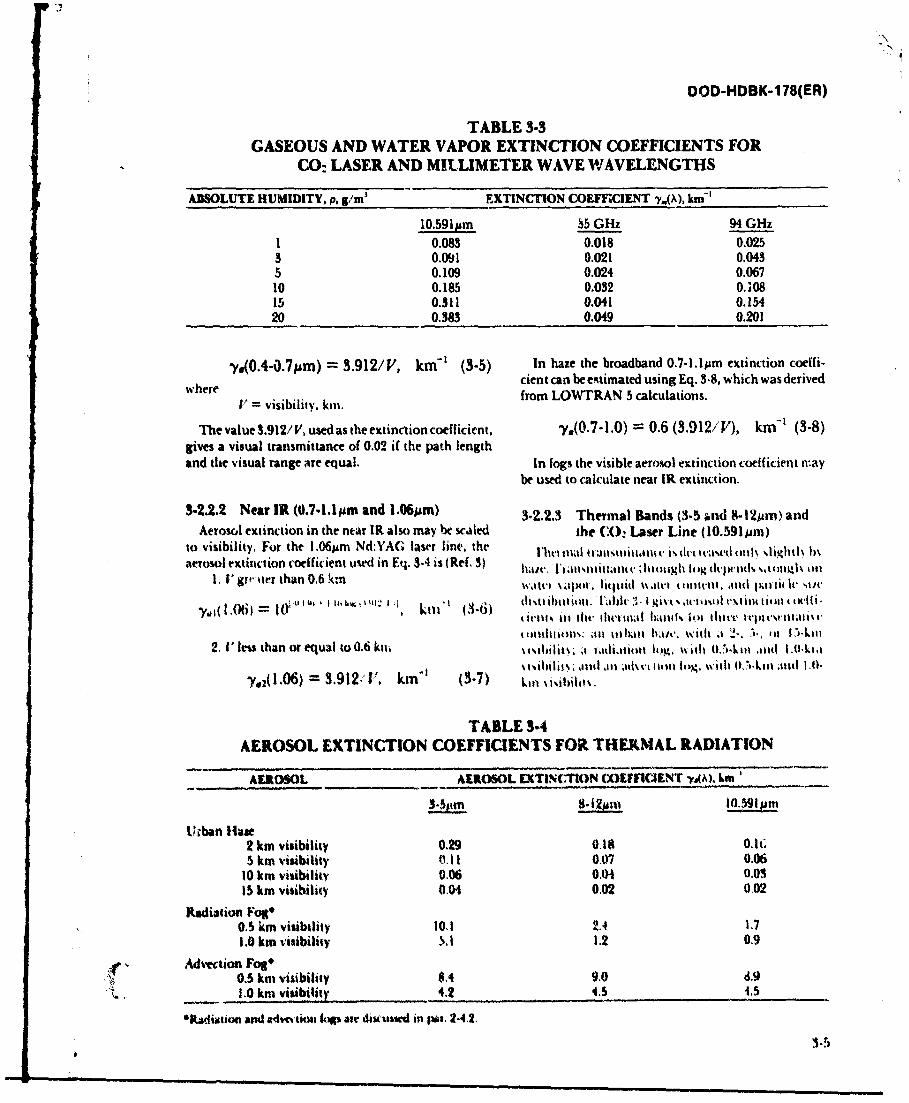
OOD-HDBK-178(ER)
TABLE 3-3GASEOUS AND WATER VAPOR EXTINCTION COEFFICIENTS FOR
CO: LASER AND MILLIMETER WAVE WAVELENGTHSASOLUTE HUMIDITY, p, g/m' EXTINCTION COEFFCIENT y,,), km-'
10.591jm S5 GHz 94 GHz1 0.083 0.018 0.0253 0.091 0.021 0.0435 0.109 0.024 0.06710 0.185 0.032 0.10815 0.311 0.041 0.15420 0.383 0.049 0.201
y.(0.4-0.7pm) 3.912/V, km-' (3-5) In haze the broadband 0.7-1.1lpm extinction coeffi-
where cient can be estimated using Eq. 3-8, which was derived
V= visibility, kin. from LOWTRAN 5 calculations.
The value 3.912/ K used as the extinction coefficient, -o(0.7-1.0) = 0.6 (3.912/V), km-' (3-8)gives a visual transmittance of 0.02 if the path lengthand the visual range are equal. In fogs the visible aerosol extinction coefficient nay
be used to calculate near IR extinction.
3-2.2.2 Near IR (0.7,1.1jm and 1.06Mm) 3-2.2.3 Thermal Bands (3-5 and 8 -12p ) and
Aerosol extinction in the ntar IR also may he scaled the (X): Laser Line (10.591pm)to visibility, For the 1.06jpm Nd:YAG laser line. the l'll1l tallnstni ita ltt. v dc( t i 1 ,lightl\ In
aerosol extinction coefficient used in Eq. 3-4 is (Ref. 3) hli/t. l IIII u i Itult Iit v .h1ijh l(itg I tlt d% 4)Il) tIO1. V" ir,.ter than 0.6 ktm wtItt't \ i liquid \ t ilt tl t .it l litirii lt t
.Y, 10 )= l il , (4 6 d 'ktl il tit .l 'd . gi\-I, ,tlut .l 'd cm l 614 titl I (k,1i.
y.,,(I.1 ti) - I()i Ii i '4 ' 5% l 1 i .'I I i kilt i ( -ti i ti h. 1ihl illil tall1%i l ol t lillet, lllitili m lii( (ill ollli: aill tlixi ll litLw ith al "I" ). 1 11i, 111il
2 ' less than or equal to 0.6 ki \ . l t hh.lg. with (),_1-kkili and I.0-.kii.1% i i i 1%,;.jllid ai lt 'tI t lll thig . w ith W I L 1 .1 4 1.0.kll ;lil
"y,2(I.06) = 3.9121, kmi (3-7) killi1,.
TABLE 3-4AEROSOL EXTINCTION COEFFICIENTS FOR THER.MAL RADIATION
AEROSOL AEROSOL LXTIN( FION (XlI FIWNT -tk\). kmi'
t;ban ilae2 km visibility 0.29 018 0.h;5 km visibility 0.11 0,07 0.06
10 km visibility 0.06 0.04 0.0315 km visibility 0.04 0.02 0.02
Radiation Fotg*O,. km visibility 10,1 2.4 1.71.0 km visibility 5.1 1.2 0.9
C Advection Fog"0.5 km visibility S4 9.0 d.91.0 km visibility 4.2 4.3 1.5
"Kadtiaion and a4wi% tiori IWi air diusuwd in i. 2.4.2.
3.5
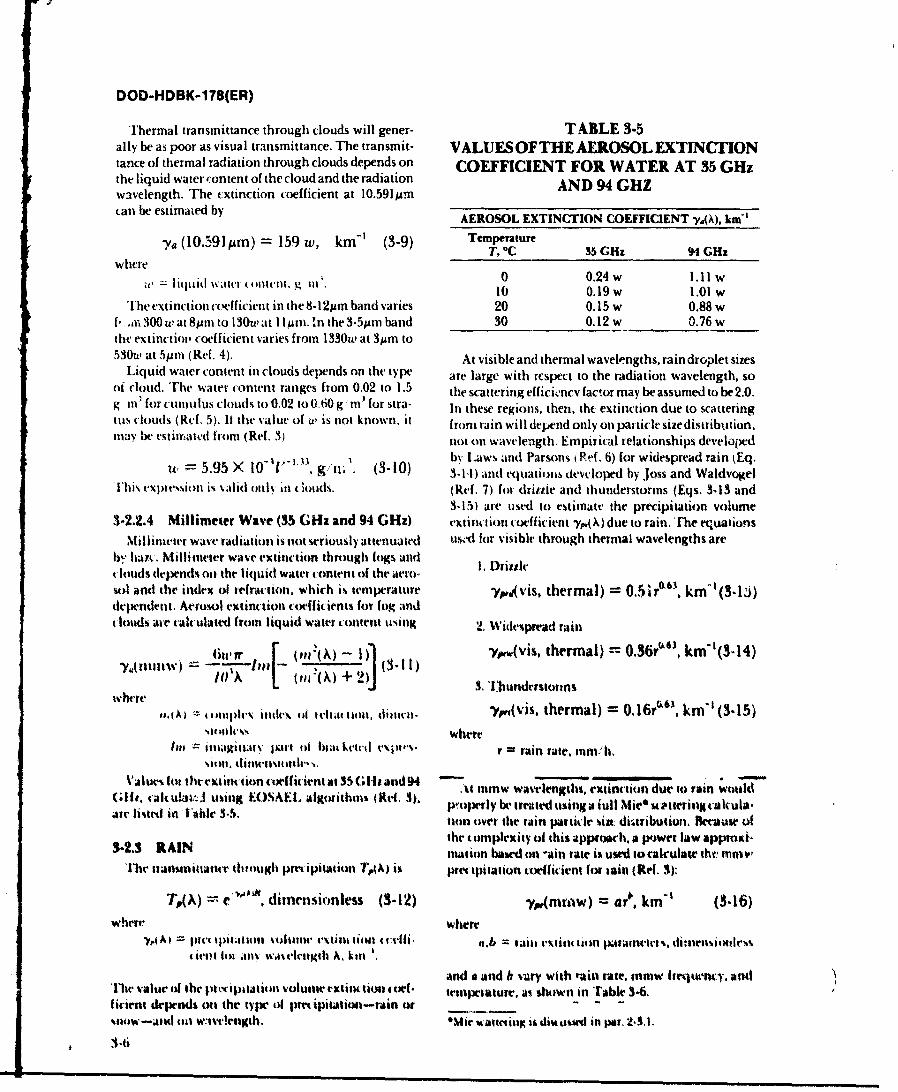
DOD-HDBK-1 78(ER)
Trhermal transmittance through clouds will gener- TABLE 3-5ally be as poor as visual transmittance. The transmit- VALUES OFTHE AEROSOL EXTINCTIONtance of thermal radiation through clouds depends onl COEFFICIENT FOR WATER AT 35 GHzthe liquid water content of the cloud and the radiation AND 94 GHZwavelength. The extinction coefficient at 1O.5911prn
c.an be estimazed by AEROSOL EXTINCTION COEFFICIENT y~Akm-'
'91 (1.Slm) = 159 w, km' (3-.9) TemperatureY,(0'T, 0C 35 GHz 9D4 GHz
whereliui ~ir0 0.24 w 1.11 W
a lhcfl.g i)10 0.19 w 1.01 WTh'leextinction co(.efficienit in the 8-121Am band v'aries 20 0.15 w 0.88 W
f, m~ 300 u, at 8pmn to 130uw at IlIlpm.' n the 3.5prn band 30 0.12 w 0.76 wthe extinctiol' coefficient varies from 1330uw at 3p~m to530wp at 5pmn (Ref. 4). At visible and thermal wavelengths, rain droplet sizes
Liquid water content inl clouds depends on the type are large with respect to the radiation wavelength, sooi cloud. The water content ranges from 0.02 to 1.5 the scattering effici .ncv factor may be assumed to be 2.0.g li' for curmlus clouds to 0.02 to 0 .60g, il' for stra- lit these regions, then, the extinction due to scatteringtius clouds (Rd. 5 ). It he value of uw is not known, it from rain will depend only onl particle size distribution,irav be estimrated from (Ref. 3) nlot onI Wavelength. Empirical relationships developed
by I- w andi Parsons RPef. 6) for widespread rain kEq.w 5.95 X 10 1 g/ n 1. (3-10) 3- 1 1) and equations devcloiptd by Joss and Waldvogel
Ylhi% expression is v.ad ouls ill lids. (Ref. 7) for dritzle and thunderstorms (Eqs. 3,13 and3-15) are used to estimate the precipitation volume
3-2.2.4 Millimeter Wave (35 GHz and 94 GHz) extim tion coefficient y~Xdue to rain.'rhe euationsMillimleter wave radiationl is not seriously attenuated us'-d for visible through thermal wavelengths are
byr hayt. -Millimeter wave extinction through fogs and I .clouds depends oil the liquid water content of the acrm-sol anti the indlex of refraction. which is temperature ypivis, thermal) = O.5i70 3 , km-'(3-W~derpendentt. Acrosol extinction cofflitients for log andc louds ar calculated from liquid water content casing 2. Widtesprad rain
'yusIw)l " I (ierb (in:(") + ')J (31)p..(vis, thermal) = 0.36y"', km-'(3-14)11) A I On(,k) 2 ]3.1 Ihunderstormns
suonicvs. wherelot ilittitiarv pairt oi blat kccil expws'. r = rain rate. mm; h.
siom linusime.,Valumt ot thlitextirsetion coeff icijent at 35 (.11,and 94 -
Gife.~ ~ ~ ~ ~ ~ ~ ~ ~~~~. tatttJuigCmmLagrtri (t.3. % lw watvlegths, extincion due to rain would(dr i.tali in s~ 14 11 3-5.:. al o it n p~ciperly be treated ussing a l l i t e i i c a u
air istd ii 1~ie 35. on over the rain particle %in du.tribution. flecause of
3-2.3 RAINthe complexity of this apprmich, a Wp)wet law appruxi-3.2.3 RAIN mation bard on -ain rate is used tot:2lculatethe rniv'
'ire tianmmtiate t"104,g0 precipi taltionl T(h) i% pme kpilation "ilfivient for lain (Ref, 3):
TpA =. e""', dimensionless (3-12) ypgmmw) =ar, km-' (3416)
whereWhere-Y At pwi u;)utlls voitinlic t.tt t-it lon clthf a.b = aits exiint tioin Patatis'eei. thatensiottdem,
it-i~li .in-41 wausclngth A. kill'.and a anid b sviry with nkin late. mmw hir jwnty. atiuI
Thr value of the proripitatioln volumtie extiincti~xi ct*.4- Itmpetature, as shown in TAble 5-.I irient depends ott the type ofl prmipitation-rarin or - -
snolW-Auuct oll W:1vvr'eth. *%fie' %~attilg is diwes' in par, 2.3.1.
1-6
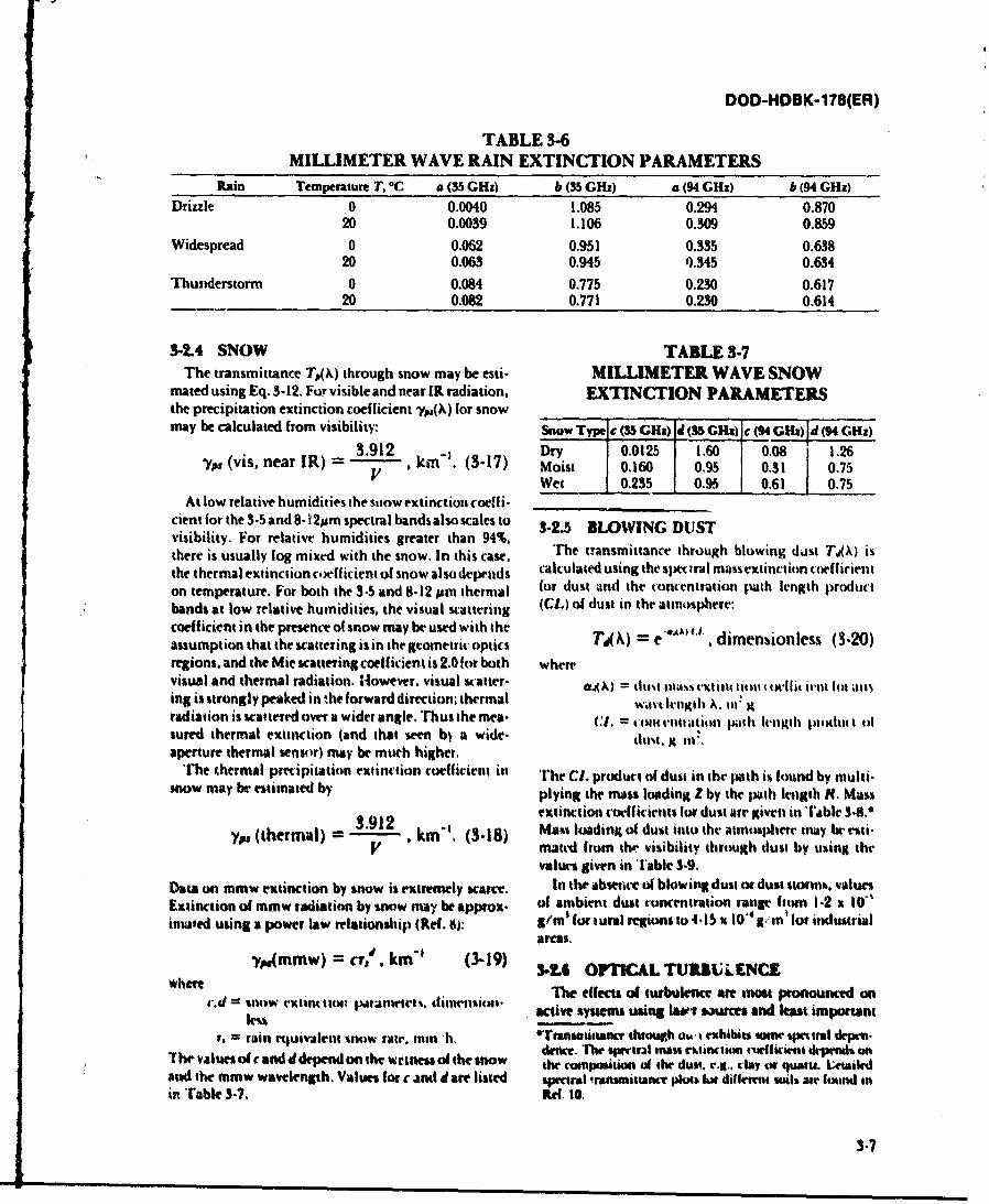
DOD-HDBK-178(ER)
TABLE 3-6MILLIMETER WAVE RAIN EXTINCTION PARAMETERS
FRain Temperature T, 0C a (35 GHz) b (35 GHz) a (94 GHz) b (94 GHz)Drizzle 0 0.0040 1.085 0.294 0.870
20 0.0039 1.106 0.309 0.859Widespread 0 0.062 0.951 0.335 0.638
20 0.063 0.945 0.345 0.634Thunderstorm 0 0.084 0.775 0.230 0.617
20 0.082 0.771 0.230 0.614
3-2.4 SNOW TABLE 3-7The transmittance T,.(X) through snow may be esti- MILLIMETER WAVE SNOW
mated using Eq. 3-12. For visible and near IR radiation, EXTINCTION PARAMETERSthe precipitation extinction coefficient yj.(A, for snowmay be calculated from visibility: Snow Type e (35 GH&) d (35 GHx) c (94 Gkh) d (94 GO:
yp vsner1)=3.912 Dr17 y 0.0125 1.60 0.08 1.26y, (i, ea R) - kin. 3-7 Moist 0.160 0.95 0.31 0.75
'/Wet 0.235 0.95 10.61 0.75At low relative humidities the stiow extinction coeff i-
cient for the 3-5 and 8-1 2pm spectral bands also scales to 3-2.5 BLOWING DUSTvisibility. For relative humidities greater than 94%. Tetasitnetrug lwn atT,)ithere is usually fog mixed with the snow. In this case, cactesnthe tsi actraug blowexincto oeff)icinthe thermal extinction coeff icient of snow also depenids cluae sn h pcrlmlsetnto ofiinon temperature. For both the 3-5 and 8-12 ism thermal for dust atnd the concentration Ibath length productbands at low relative humidities, the visual scattering (CL) of dust in the atmosphere:coefficient in the presence of snow may be used with the Td ~ e iesoles( 0assumption that the scattering is in the geometric optics =e ~ dmnines(-0regions, and the Mie scattering coefficient is 2.0 for both wherevisual and thermal radiation. However. visual scatter- 0oM (11A lllas rI vxit tI%( t tl liit itl Itit all)ing is strongly peaked in the forward direction, thermal wav Ilih A. III Kradiation is scattered over a wider angle. Trhus the inea- C1. 4 om e-nutation pilth ltuligth pltxltut t tIsnured thermal extinction (and that swon bj a wide- dim,~ gfi'aperture thermal sensor) may be much higher,
The thermal precipitation extinction coefficient in The C1. product of dust in thr path is found by multi.snow may, be estimated by plying the mass loading Z by the path length Ht. Mass
3.912extinction coefficients for dust are given in fable 38.*y,w (thermalI) -.1 . kin"'. (3-18) Mass loading of dust into the atmosphere may be rei.
V matcd frum thir visibility through dust by using thevalues given in Table 3.9.
Daaon mmw extinction by snow is extremely bcace In the abseuict of blowing dust or dust stormik. values.Extinction of mmw radiation by snow may be Approx. of ambient dust concentration ranige h I tun 1-2 It 10'instAted using a power law relationship (Ref. 6):m o ualrgost .1 0~g s lforindutrial
ygemmw) = evA km' (3-19) 3-16 OPTICAL TUSBUlENCEwherecd=%lwetiitotptrivr iiuiin The effects of turbulence ane mass pronounced on
IeCU active sysetes using hwavr auce and least importantr.= ain etquivalent %now fair., mminii. *Ttiattsr thruotght ak exhibits twie spetrl depem.
1hrvales f candd dpen onthewetk f te sow dence. The spmur~l mlas rhtinciwm cuwfiocint depends onihealusocanddpenonhew~tessfmthnw copio (A cthe dust. rejg.. clay tr quot- 1;wil
And the mmw wavelength. Values (fo c 4nd d art listed spectral iransiitance plois lot dillewrt i "is we lfound inin Table 3-7. Ref. 10.
3.7
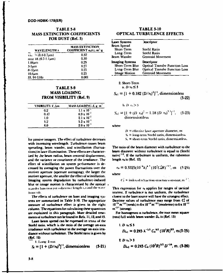
DOD-HDBK-178(ER)
TABLE 3-8 TABLE 3-10MASS EXTINCTION COEFFICIENTS OPTICAL TURBULENCE EFFECTS
FOR DUST (Ref. 3)Laser Systems )escriptor
MASS EXTINCTION Beam SpreadWAVELENGTH A COEFFICIENT OA,\), m2/g Short-Term Strehl Ratio
% isi ,(0.4-0.7pm) 0.32 Long-Term Strehi Ratio
near IR (0.7-1.lm) 0.30 Beam Wander Centroid Movement
1.061in 0.29 Imaging Systems Descriptor3-5uAm 0.27 Short-Term Blur Optical Transfer Function Loss8-12prn 0.25 Long-Term Blur Optical Transfer Function Loss10. 6pMo 0.25 Image Motion Centroid Movement33. 94 GHz 0.001
2. Short-TermTABLE 3-9 a. D/ro :_ 3
MASS LOADING SSl = [1 + 0.182 (D/ro)2 '- , dimensionlessFROM VISIBILITY (Ref. 9) (3-22)
VISIIILITY I'. km MASS LOADING 2. i m I) r > 3
0.2 1.1 x 0.'0.47 6.9x i0" S, = [! + (1) ro)* - 1.18 (1) ro)'V]. (3-23)1.0 2,1 x 10" dimIensionless3.2 5.2 x 10'8.0 2.0 x 10' where
1) = elet tivtc l tl ijwritait' diimneter, inSt = lotig-tetil Stitehl ratio. dlinlsiotliss
for passive imagers. The effect of turbulence decreases . l = ort-tt-1nt Stthl ra.tio, diinctsiollrs.with increasing wavelength. Turbulence causes beamspreading. beam wander, and scintillation (fluctua. The ratio of the beam diameter with turbulence to thetions)in laser illumination.'Ihe effects are character. beam diameter without turbulence is equal to (Strehliwed by ,he beam radius, beam centmid displament. ratio)'t*. If the turbulence is uniform, the coherenceand the variance or covariance of the irradiance. The length to is (Re(. 12)effect of scintillation on system pcrlormance is de-creased by averaging the power fluctuations over the 3= .325010""A) (10 (,R) ,n (-21)receiver aperture (aperture averaging), the larger thereceiver aperture, the staller the effect of scintillation..... .
Imaging system degradation by turbulencreinduced C". = inth- ! tiofit 1 ll tlt t 1111V tit4 t1041. Mblur or image motion is characteried by the optical11 ,titdi 1h41 I 111 telt i lii iltt o.1th 11, 4 tIh" ;tr This expression fur eo applies for ranges of tacticall11ltsu 111. intrest. If turbulen-.v is not unilorm, the turbulence
The efects of turbulence on later and imaging svs- closest to the later source will have the strongest effect.tetms are summarized in Table 3-10. The appropiate Daytime values of turbulence may range from d ofmeasure of turbulence effect is given in the right 10"4m'1(ewak)to6x 10-"m-'(modnate)to6x1t0"column. The equations for calculating these quantities m" I (strong),are explained in this paragraph, Morm detailed treat- For honmseneo is turbulence, the root mean squarements of turbulence can be found in Rd*s. 1 12. and I 3. (rm) full width beam wander D. is (Re(. I)
Lar beam spread can be expretsd in trints of theSet111 ratio, which is the ratio of the averageon-axis I. ), re5 3irradiance with turbulence to the average on-axis ira- Di = 0.245 0 , 0R)', m(3-25)diance without turbulence. The Stle uio i given by , C,(Ref. 12) 2, D'ro> $
= [I + (D/vo)2]" , dimensionless (3-21) D., = 0.245 C. (10WOR)W D". m. (3-26)
3-8
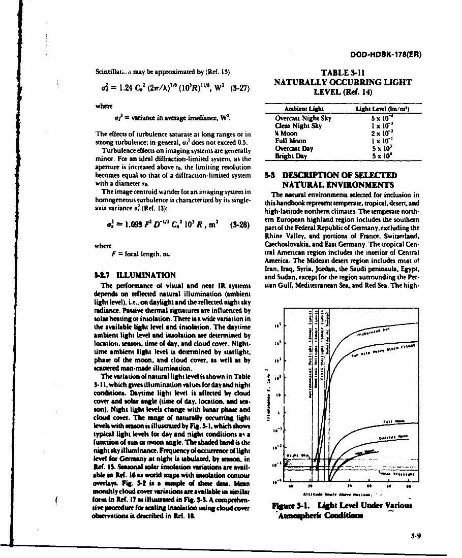
DOD-HDBK-178(ER)
Scintillat a may be approximated by (Ref. 13) TABLE 3-11NATURALLY OCCURRING LIGHT
S1.24 C,2 (2,r/X)'1 (103R)"116, W2 (5-27) LEVEL (Ref. 14)
where Ambient Light Light Level (Imi')01 = variance in average irradiance, W2. Overcast Night Sky 5 x i -
Clear Night Sky I x 10-1The effects of turbulence saturate at long ranges or in l Moon 2 x 100strong turbulence; in general, oi2 does not exceed 0.5. Full Moon 1 x 10-'
Turbulence effects on imaging systems are generally Overcast Day 5 x 101minor. For an ideal diffraction-limited system, as the Bright Day 5 x 10⁴aperture is increased above ro, the limiting resolutionbecomes equal to that of a diffraction-limited system 3-3 DESCRIPTION OF SEwith a diameter ro. NATURAL ENVIRONMENTS
The image centroid wander for an imaging system in The natural environments selected for inclusion inhomogeneous turbulence is characterized by its single- this handbook represent temperate, tropical, desert, andaxis variance oX (Ref. 13): high-latitude northern climates. The temperate north-
er European highland region includes the southern=,' 1.093 P2 D "t' C. 10' R, m2 (3-28) part of the Federal Republic of Germany, excluding the
Rhine Valley, and portions of France, Switzerland,where Czechoslovakia. and East Germany. The tropical Cen-
F = focal length. m. tral American region includes the interior of CentralAmerica. The Mideast desert region includes most ofIran. Iraq. Syria, Jordan, the Saudi peninsula. Egypt,
3-.7 ILLUMINATION and Sudan. except for the region surrounding the Per-The performance of visual and near IR systems sian Gulf, Mediterranean Sea. and Red Sea. The high.
depends on reflected natural illumination (ambientlight level), i.e.. on daylight and the reflected night skyradiance. Passive thermal signatures are influenced byZsolar heating or insolation. There is a wide variation inthe available light level and insolation. The daytimeambient light level and insolation are determined bylocation, season, time of day, and cloud cover. Night- 16
time ambient light level is determined by starlight. 6phase of the moon. and cloud cover, as well as by 16)scattered man.made illumination.
The variation of natural light level is shown in Table 6 tea5- II, which gives illumination values for day and nightconditions. Daytime light level is affected by cloudcover and solar angle (time of day, location, and sea.son). Night light levels change with lunar phase andcloud cover. The nge of naturally occurring lightlees with season is illumuaed by Fig. 3.1. which showstypkal light levels (or day and ntlght conditions a&% a"peafunction o sun or moo angle, The shaded band is thenight sky illuminance. Frtquency of occurrence of lightlevel for Germany at niglh is tabulated. by season, inRet IS. Seasonal solar insolation vaiiations an avail. ,"-able in Ref. 16 as wold map with imolation contour ... i . .overlays. Fig. S,- i a sample of these daa. Mean ** to . . ,monthly coud cover variations are available in similar Alms. .e* "W" ,,.,+, .,fom in Ref. I? as illustrated in Fig, 3-3. A compreten.rive proceue for ,aling insolaton using cloud cover Figure 3.1. Light Level Under Variosobwration is described in Re. I&. "tsapiep r CAdidom
3-9
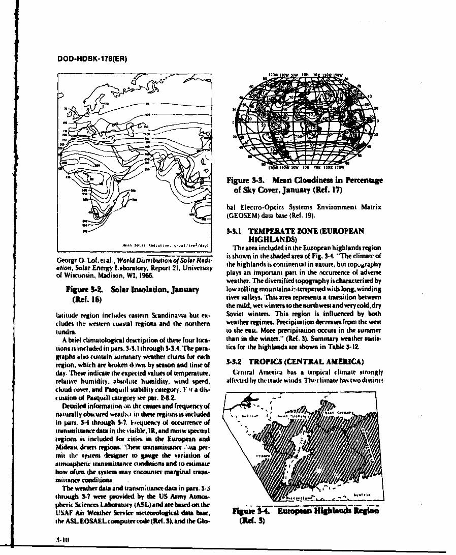
DOD-HDBK-178(ER)
1?70W I10W 5OW 103 702 1303 170W
-. - - -------
200
Figure 3-3. Mean Cloudiness in PercentageISof Sky Cover, January (Rf. 17)
bat Electro-Optics Systems Environment Matrix(GEOSEM) data base (Ref. 19).
3-.1 TEMPERATE ZONE (EUROPEANHIGHLANDS)
S4. .. S(.La, ftet,, .. qi o2, t,:/ The area included in the European highlands region
George 0. Lof. et at.. World Distribuion of Solar Radi- is shown in the shaded area of Fig. 3-4. "The climate of
ation. Solar Energy Laboratory. Report 21. University the highlands is continental in nature, but topugraphyof Wisconsin, Madison. Wl, 1966. plays an important part in the osccunence of adverse
weather. The diversified topography is characterized byFigure 3-2. Solar Insolation, January low rolling mountains i-,terspersed with long, winding
(Ref. 16) river valleys. This ares represents a transition betweenthe mild, wet winters to the northwest and very cold, dry
latitude region includrt eastern Scandinavia but ex. Soviet winters. This region is influenced by bothcludes the uestem coastal regions and the northern weather regimes. Precipitation decreases from the westtundra. to the eat. More precipitation occurs in the summer
A brief climatological description o( these four loca- than in the wintr." (Re(. 3). Summary weather statis-tions is included in par%. 3.3. 1 through 3-3.4. The psra. tics for the highlands are shown in Table 3- 12.graphs also contain sumotary weather charts for eachregion, which are broken &d)wn by season and time of 332 TROPICS (CENTRAL AMEICA)day. These indicate the expected values of temperature. Central America has a tropical climate stronglyrelative humidity. absolute humidity, wind speed, alfected by the trade winds'The climate has twodistinctcloud covet, and Pasquill stability category. F ir a dis-cussion of Paquill category we par. 2.6.2. -
Detailed information o the causes and frequency of I *4"
naturally obscured weatvwi in these regiom is included V, ,."",,in parts. 3-4 through 3-7, Vvequency of occurrence of "transmittance data in the 'isible. IR. and mmw spectralregion% is included fut ritieu in the European andMideast dsert regions. These transmittance ,;.sa per-mit the system designer to pupg the variation ofatmospheric transmittance conditions and to estimatehow often the system may encounter marginal trans-mittancr conditions.
The weather data and tantmttanc data in pars. 3--through 3.7 were provided by the US Army Atmos-pheric Sciences Laboratory (ASL) and are based on theUSAF Air Weather Service wttorolaial dat base. fgure 34. Eur Mpean Higlands Regiothe ASL EOSAELcomputer code (Rf. 3). and the Glo- (Rd. 3)
3.-10
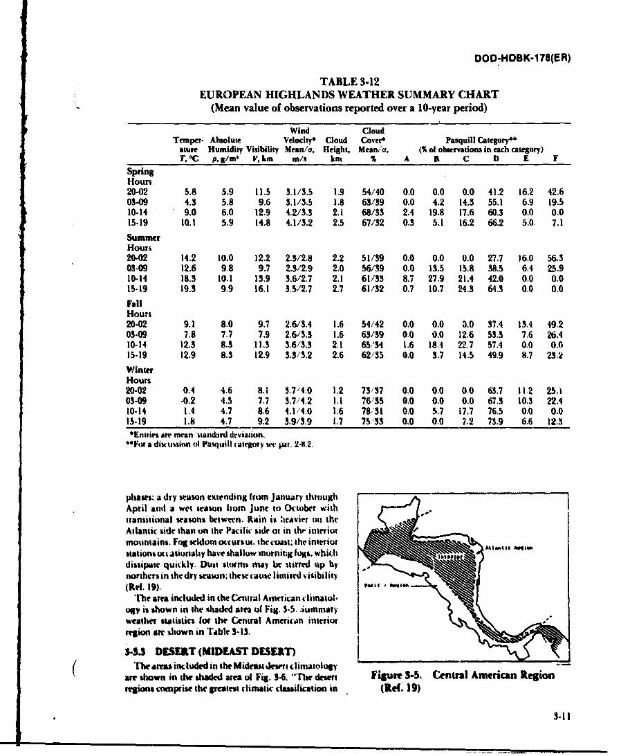
DOD-HDBK-178(ER)
TABLE 3-12EUROPEAN HIGHLANDS WEATHER SUMMARY CHART
F (Mean value of observations reported over a 10-year period)
Wind CloudTemper- Absolute Velocity* Cloud Cover* Pasquill Category**
ature Humidity Visibility Mean/a, Height, Mean/a, (% of observations in each category)T. °C P, g/ms V, km m/s km % A 3 C D E F
SpringHours20-02 5.8 5.9 11.5 3.1/3.5 1.9 54/40 0.0 0.0 0.0 41.2 16.2 42.603-09 4.3 5.8 9.6 3.1/3.5 1.8 63/39 0.0 4.2 14.3 55.1 6.9 19.510-14 9.0 6.0 12.9 4.2/3.3 2.1 68/33 2.4 19.8 17.6 60.3 0.0 0.015-19 10.1 5.9 14.8 4.1/3.2 2.5 67/32 0.3 5.1 16.2 66.2 5.0. 7.1
SummerHours20-02 14.2 10.0 12.2 2.3/2.8 2.2 51/39 0.0 0.0 0.0 27.7 16.0 56.303-09 12.6 98 9.7 2.3/2.9 2.0 56/39 0.0 13.5 15.8 38.5 6.4 25.910-14 18.3 10.1 13.9 3.6/2.7 2.1 61/33 8.7 27.9 21.4 42.0 0.0 0.015-19 19.3 9.9 16.1 3.5/27 2.7 61/32 0.7 10.7 24.3 64.3 0.0 0.0
FallHours20-02 9.1 8.0 9.7 2.6/3,4 1.6 54/42 0.0 0.0 0.0 37.4 13.4 49.203-09 7.8 7.7 7.9 2.6/3.3 1.6 63/39 0.0 0.0 12.6 53.3 7.6 26.410-14 12.3 8.3 11.3 3.6/3,3 2.1 65/34 1.6 18.4 22.7 57.4 0.0 0.015-19 12.9 8.3 12.9 3.3/3.2 2.6 62/35 0.0 3.7 14.5 49.9 8.7 23.2WinterHours20-02 0.4 4.6 8.1 3.7,4.0 12 73/37 0.0 0.0 0.0 63.7 11.2 25.03-09 -0.2 4.5 7.7 37,4.2 1.1 76/35 0.0 0.0 0.0 67.3 10.3 22.410-14 1.4 4.7 8.6 4,1/4.0 1.6 78,31 0.0 5.7 17,7 76.5 0.0 0.015-19 1.8 4.7 9.2 3,9/3.9 1.7 75/33 0.0 0.0 7.2 73.9 6.6 12.3*Entft aier manrttdard deviation."For a discunion tl Pasquill tatmory we pgar, 2-8,2.
phases: a dry wason extending (rom January thtoughApril anid a wet season from June to October withtransitional wasons between. Rain is havier oil theAtlantic side than on the Pacilic side or in th. interiormountains. Fog seldom octurs ut. the coast. the interiorstations ct :asioraaly have shallow morning togs. which lot*dissipate quickly. Dust stonms may be stirred up bynorthers in the dry season; thew rause limited visibility(3e.. 19),
"M arm included in the Central Amrican climatol.op is shown in the shaded area of Fig. 3-5. ,iummaryweather statistics [or the Central American interiorregion are shown in rable 3-IS.
133 DESERT (MIDEAST DESERT)"rhe ars included in the Mideu desert climatology
aft swwn in the shaded area of Fig. 3$. "The dewrt Figure 3-5. Central American Regionreglions comprise the greates climatic cmication in(e.
3-l1
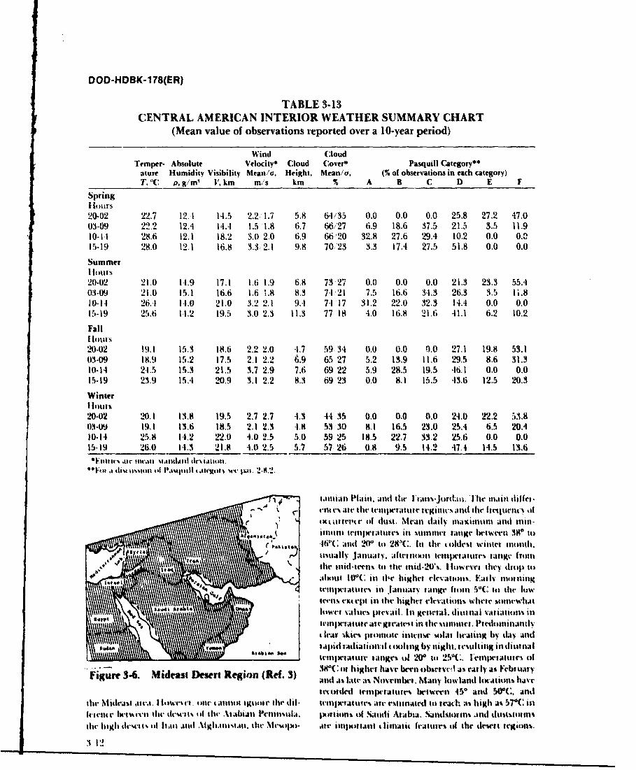
DOD-HDBK-178(ER)
TABLE 3-13CENTRAL AMERICAN INTERIOR WEATHER SUMMARY CHART
(Mean value of observations reported over a 10-year period)
Wind CloudTemper- Absolute Velocty* Cloud Cover* Pasquill Category**
ature Humidity Visibility Mean/a, Height, Mean/a. (% of observations in each category)T, 'C p, g/m V, km m/s km % A B C D E F
Spring[1ours20-02 22.7 12.1 14.5 2.2 1.7 5.8 64/35 0.0 0.0 0.0 25.8 27.2 47.003-09 22.2 12.4 14.4 1.5 1.8 6.7 66/27 6.9 18.6 37.5 21.5 3.5 11.910-I-I 28.6 12.1 18.2 3.0 2.0 6.9 66 '20 32.8 27.6 29.4 10.2 0.0 0.115-19 28.0 12.1 16.8 3.3 2.1 9.8 70,23 3.3 17.4 27.5 51.8 0.0 0.0
Summeri Iours20-02 21.0 11.9 17.1 1.6 1.9 6.8 73,27 0.0 0.0 0.0 21.3 23.3 55.403-09 21.0 15.1 16.6 1.6 1.8 8.3 7-1 21 7.5 16.6 34.3 26.3 3.5 11.810-14 26.A 1-.0 21,0 3.2 2.1 9.4 74 17 31.2 22.0 32.3 14.4 0,0 0.015-19 25.6 1-1,2 19,5 3.0 2.3 11.3 77 18 4,0 16.8 21,6 41.1 6.2 10.2
FallSfloillS
20-02 19.1 15.3 18.6 2.2 2.0 4.7 59 34 0.0 0.0 0.0 27.1 19.8 53.103-09 18.9 15.2 17.5 2.1 2.2 6.9 65 27 5.2 13.9 11.6 29.5 8.6 31.310-1I1 2-1.5 15.3 21.5 3.7 2.9 7.6 69 22 5,9 28.5 19.5 46.1 0.0 0.015-19 23.9 154 20.9 3.1 2.2 8.3 6923 0.0 8.1 15.5 43.6 12.5 20.3
WinterI loiuts20-02 20.1 13.8 19.5 2.7 2.7 4.3 44 35 0.0 0.0 0.0 24.0 212.2 53.803-09 191 13.6 18.5 2.1 2.3 4.8 53 30 8.1 165 23.0 25.4 6.5 20.410-14 25.8 14.2 22.0 4.0 2.5 5.0 59 25 18.5 22,7 33.2 25.6 0.0 0.015-19 26.0 14.3 21.8 4t.0 2.5 5,7 57 26 0.8 9.5 14.2 47.4 14.5 13.6
t urlt'llt"r ,I c li. NtIll i lill tluliintni uuiutl man
"F111*a 1(.11al A1d 0 I)2$C.I art ltt waar on
0I'mO a is[ , Plaul l lI, mll ,,t l %vt- I w 2.l9.2-
' P.) tawilliall Pllaill. ;afd te l'latiw-jordmilThe na11.ill tfirm.
17 , eil Ia tilt -rr tlla |taltitl a gilil. and thcer altl i lt p to
r 4ItU 0tr(tr Of chl igt. Mea- (aity klaximuI nad Inin-
A lt .. i11111111 I nIll l t-lu inl w l w inic . |all Iwt rl 38n it)Iowa-,, and 2 ato 28C.In the toldst wi.nrt imnthh
lite lilte il-l pI totr r i id.N'%, llowrvri hiey tithvp itl~xa j lwIOC ilit highr elrvalioU . Vatly twelhing
leltillil-lalltltl' ill .l 11Mlttt ill iIKt- (ttllll 5( It) the" low
' llnl~~Wll%. rx(epI inl the higlhrt rlrVatlionsl wiltI wiIIeIwhat
i ll'lll~l'l'alllvall" Ivillil. I I lllill d t'1l.3 VA6360llll illl
" pid r~li.alioai:at isaslhng by night. ruulling in tlitna;
it ,all-a lTur tligt. id 20 it 2.5 C . IrIIwtItamim i o
Figure 3-6. Mideast Desert Region (Re(. 3) a9lC t htg e Nave ben Many Iuwlanal ar.iahaitiat
attottred trin-ratur-m be wa-ten 45" And 50C. andtir Mitdras aw.a. I IItw ,,til l" li lll tltt l lligtit' lie dii- trltiljtiltaa la- Jra- a-liteiialtt to rcat:. ;%% high k% 57'C ilnIta-tl.11r Iit-tut-trtt tlt- tl-wa1 it h .\tAlabiall Palainl 1.l, Ixittiotns of .atdi Artbia. Siandtsotrlns ind afustitinstile h1aglh dIra|M: 0 .I411 .1111 .1lIKh.auaLM. ". lt-A~la- art- ilnixllita . linltatit fralutal of the tit-sell regioM.
,3 12
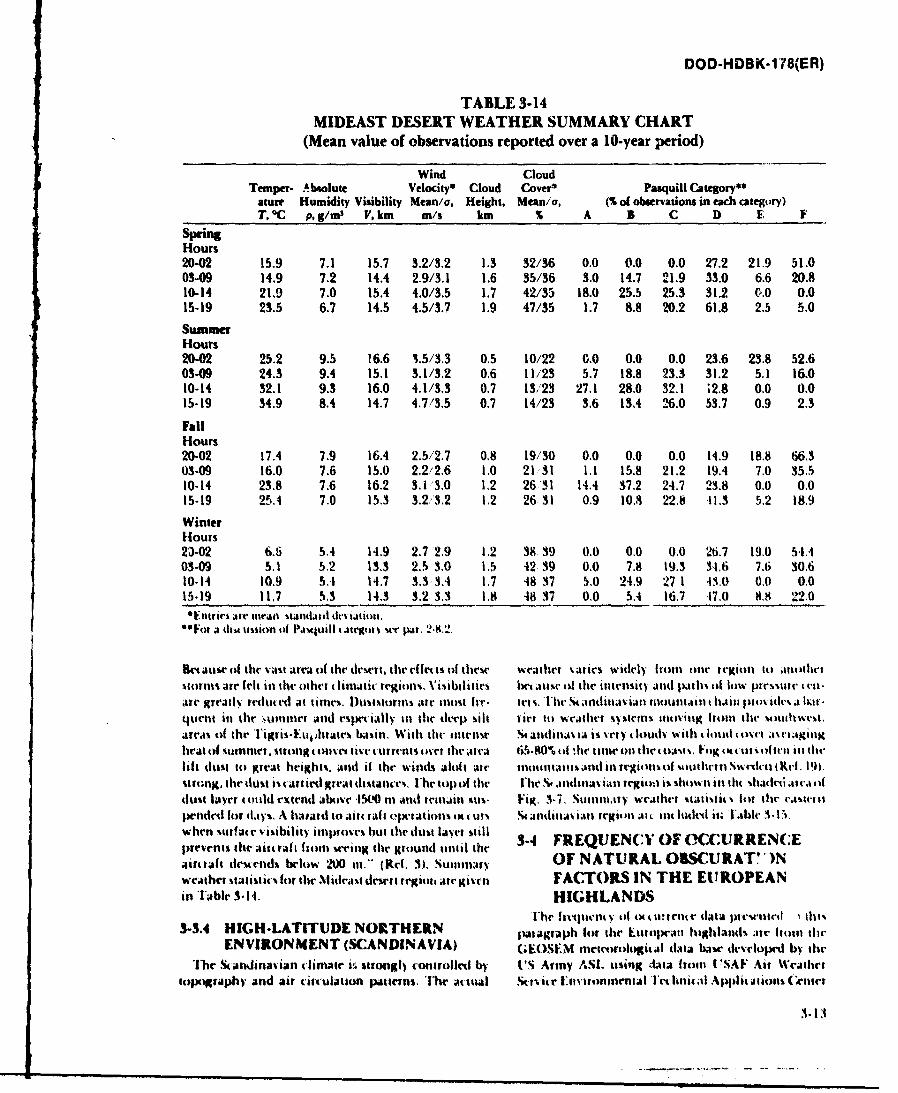
DOD-HDBK-178(ER)
TABLE 3-14MIDEAST DESERT WEATHER SUMMARY CHART
(Mean value of observations reported over a 10-year period)
Wind CloudTemper- Absolute Velocity* Cloud Cover* Pasquill Category"
ature Humidity Visibility Mean/a, Height, Mean/a, (% of observations in each category)T, *C p, g/m s V, km m/s km % A B C D E F
SpringHours20-02 15.9 7.1 15.7 3.2/3.2 1.3 32/36 0.0 0.0 0.0 27.2 21.9 51.003-09 14.9 7.2 14.4 2.9/3.1 1.6 35/36 3.0 14.7 21.9 33.0 6.6 20.810-14 21.9 7.0 15.4 4.0/3.5 1.7 42/35 18.0 25.5 25.3 31.2 0.0 0.015-19 23.5 6.7 14.5 4.5/3.7 1.9 47/35 1.7 8.8 20.2 61.8 2.5 5.0
SummerHours20-02 25.2 9.5 16.6 3.5/3.3 0.5 10/22 0.0 0.0 0.0 23.6 23.8 52.603-09 24.3 9.4 15.1 3.1/3.2 0.6 11/23 5.7 18.8 23.3 31.2 51 16.010-14 32.1 9.3 16.0 4.1/3.3 0.7 13/23 27.1 28.0 32.1 '2.8 0.0 0.015-19 34.9 8.4 14.7 4.7/3.5 0.7 14/23 3.6 134 26.0 53.7 0.9 2.3
FallHours20-02 17.4 7.9 16.4 2.5,2.7 0.8 19/30 0.0 0.0 0.0 14.9 18.8 66.303-09 16.0 7.6 15.0 2.2/2.6 1.0 21r31 1.1 15.8 21.2 19.4 7.0 35.510-14 23.8 7.6 16.2 3. 1,3.0 1,2 26'31 14.4 37.2 24.7 23.8 0.0 0.015-19 25.4 7.0 15.3 3.2/'3.2 1.2 26 31 0.9 10.3 22.8 .11.3 5.2 18.9
WinterHours23-02 6.6 5.4 14.9 2.7 2.9 1.2 38 39 0.0 0.0 0.0 26.7 19.0 54.403-09 5.1 5.2 13.3 2.5 3.0 1.5 42 39 0.0 7.8 19.3 34.6 7.6 30.610-14 10.9 5.1 14.7 3.3 3.1 1.7 48 37 5,0 24.9 271 43.0 0.0 0.015-19 11.7 5.3 14.3 3.2 3.3 1.8 48 37 0,0 5.4 16.7 4t7.0 8,8 22.0'Entiris jrr nieait tLnttr t'ijgtbn.t
60F"of a d t wk~ionl $4 P.Implill tattlr l %v 1. .8-2.,
URtlausw of the vaul area of the derrt, the elt ts of these wetlJtwr sAric widly 1rou1 one regiol tiitlwt.torli are felt il tl other 4linatiA regiols. Visibililics lw J.u" of the ittielsit"y ald Mlih of low p~re " a (.t-atre grutls redhtrit at tles. )uststortns tia IoSIr Iwrr- tess. lhe St ,nltt.oiuai uiblOhti* htiit lilt,% he% a hat .qurttt ill tile -. titinel atnd rsp- ially In the (feel) silt fict t) weith'er ltettlt% Illitig |1"l11 the uslt.hwtS.
areas of the T~igrs- he i., With tht-i" rbw, %a a 11i 14 a 1A tisdaia i I sery t oud I with l h011d osri Jc; gul gIseat of| sttuet,~ sitlng tse\i taw"t turrtnIVts oser the julcal 65.8 '0 ut ;ltt IIl(W t) the iat f",g ,it t I1'Oftt'l tat thw
lift dust to great heights. alnd if the winds aloh ate taaou sd in1 rAiolnof ottheil.l h %swc (KRIl. 19).strong. the dust i%(at itiled great dallntcs, 'h top o the 1'h . .,ndinlla ill regii it showits i tht hladti laat, (dust layer tlld extend lbove l54. nia arid rina iil wus. Fig. 3.7. Suminal ) wrAtht st.ttiis , lit th- ea;wte ispencd" for day%. A hlasatld to anii rafll .oflatioi% ut a w-- ;ullAtlla ian lleginl (,l I nlt luili it, lilei 3.1 .
w hen urf a te visibility ilaptl wes hut il ted t la ti stillprevents the ai fraft |tor wring the ground util tie - FREQUENCY OF CCURRENCEtairtiat desirtds below 200 I." (Ref. 3), Suntiarv OF NATURAL OBSCURAT"Nweather statisti for the Slidrat dewrt regiota tati giv'i FACTORS IN THE EU ROPEANn 'Table 3.14. HIGHLANDS
.The lu hr ltlunt of ot a wrer data pi tir etl 1 Oil%$-3.4 HIGH-LATITUDE NORTHERtN ~lialaglaph lot the lUlrlwttll highlands MV Ito- ll tile
ENVIRONMENT (SCANDINAVIA) (GEOSEM mreteoologicl diata base i erhiopd by the
The S-anidinavian limair iai strogll (onlrolletd by U2S Army ASt. using cata fron U'SAF Air Weathrrit0w)KrfAphy and air tiruliation patteins. '11w m-wal !Kiviic tnironmenital 'lt- i.Au Applit iioin (Tiener
3-13
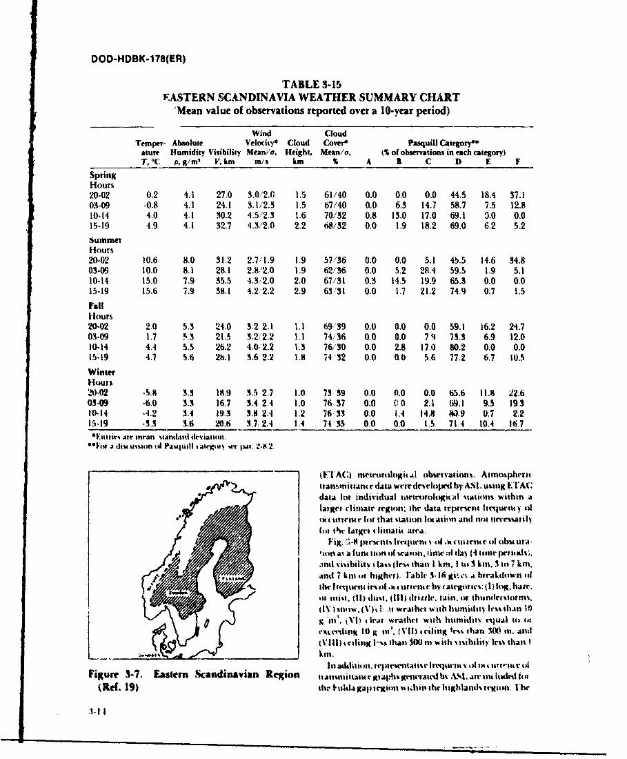
DOD-HDBK-178(ER)
TABLE 3-15EASTERN SCANDINAVIA WEATHER SUMMARY CHART
'Mean value of observations reported over a 10-year period)
Wind CloudTemper- Absolute Velocity* Cloud Cover* Pasquill Category**ature Humidity Visibility Mean/a, Height, Mean/a. (% of observations in each category)T, °C p, g/m s V, km m/s km % A 3 C D E F
SpringHours20-02 0.2 4.1 27.0 3.0/2.0 1.5 61/40 0.0 0.0 0.0 44.5 18.4 37.103-09 -0.8 4.1 24.1 3.1/2.3 1.5 67/40 0.0 6.3 14.7 58.7 7.5 12.810-14 4.0 4.1 30.2 4.5/2.3 1.6 70/32 0.8 13.0 17.0 69.1 3.0 0.015-19 4.9 4.1 32.7 4.3/2.0 2.2 68/32 0.0 1.9 18.2 69.0 6.2 5.2SummerHours20-02 10.6 8.0 31.2 2.7/1.9 1.9 57/36 0.0 0.0 5.1 45.5 14.6 34.803-09 10.0 8.1 28.1 2.8/2.0 1.9 62/36 0.0 5.2 28.4 59.5 1.9 5.110-14 15.0 7.9 35.5 4.3/2.0 2.0 67/31 0.3 14.5 19.9 65.3 0.0 0.015-19 15.6 7.9 38.1 4.2'2.2 2.9 63/31 0.0 1.7 21.2 74.9 0.7 13.5
FallHours20-02 2.0 5.3 24.0 3.2 2.1 LI 69/39 0.0 0.0 0.0 59.1 16.2 24.703-09 1,7 5.3 21.5 3.2/2.2 1.1 74,/36 0.0 0.0 79 73.3 6.9 12.010-14 44 5.5 26.2 4.0,2.2 1.3 76/30 0.0 2.8 17.0 80.2 0.0 0.015-19 4.7 5.6 21 3.6 2.2 1.8 74 32 0.0 0.0 5.6 77.2 6.7 10.5
WinterHours20-012 ,5, 3.3 18.9 3.5 2,7 1.0 73 39 0,0 0,0 0.0 65.6 11.8 22.603-09 -6.0 3.3 16,7 3.4 2.4 1.0 76 37 0,0 00 2.1 69.1 9.5 19.310-14 ,4.2 3.4 19.3 3,8 2.4 1.2 76"33 0,0 14 14.8 &.9 0.7 2.215-19 .3.3 3.6 20.6 3.7 2.4 1.4 74 35 0.0 0.0 1.5 714 10,4 16.7OF.1ttlir- 1retail t attdatd t ion sa ,tus.
Oe"il i dim ,mion t A Pautuill tatrgt ilct% .,%m t'
(FI'AC) m toruloghiai obsrrvatiols. Aimosphefir* latnmittanl r data wnr drvrh)twd by A. tts.Ing ETA(
data lot individual lnri oloii~al utatiolni within alargrr 1'itate rrgson. thr data terrsrlt [ti tlnt y 14
a.' o tist Urtrnr hfo ihat %talon Ilt mi m and not ntrrsatily,G)t Ow largt m lnatit Atra.
Fig, :]-$ |rwnts hrjucnt ' of is tit telir f ibbi tit:,-'%iot al fun* tia)fl of wa)lon. tinw of da (4 limnr petaith.amld viibsiitv t la,% (Ilw thare I kin. I to 3 kin. 3 to 7 km.
rift% ;and 7 kin in hight). -ablr 3-16 git- A bakdowi of,' I~~~he" Iwrl1otl4 sst of .ke tttl4l e by ats-gow i-", (3 fo}|tqc. hair.
tn mist, (11) dut. (ill) dsiule, tai. it thutldr,.otns.(IV) %now. (Ii 1. .11 wrather with hurnidit. le%. than 10g In', VI) 4leI- wrathrt with humIdity VILUaI I s OtVrLC'Tditg I0 g in'. (VII) triling t1rq* than ,I0 s. and(VIII) isiling l-s than 30 in witht ,ishility Ir thai I
In akitit. tqrneuentati e Itlrptri %Aix f it sal;-mr rtFigure 3-7. FAstTrn Scandinavian Region tansmitsvugtaphlK-wlatrdbv0 AMl.atr im hts its(Re{. 19) tir 1I-lia KAI Irgi'h wi~lhis thr highlanIts tgiei, the
'.31
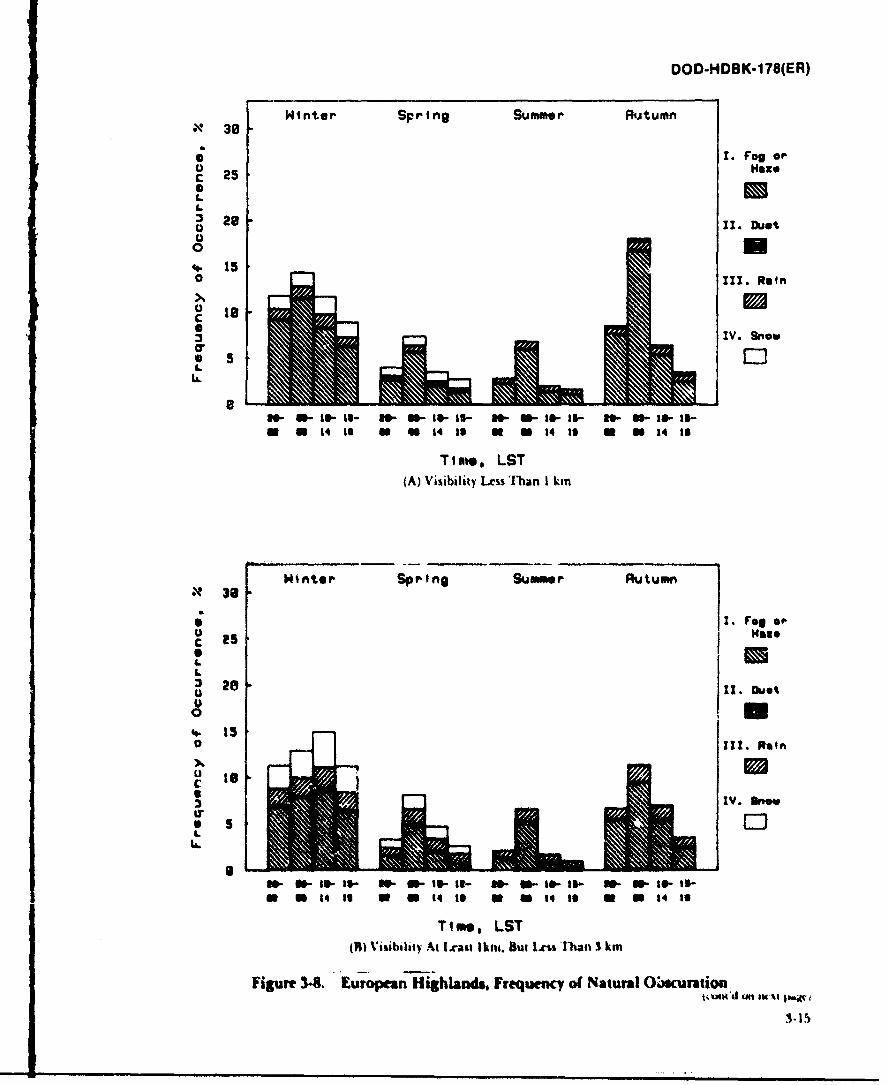
DOD-HDBK-178(ER)
Winter Spring Summer Rutumn• 38
*1. Fog orO HazeC 25
L
= 28 i.~.20 11. Dust
0
. 150 111. RainX
:3 IV. Snow
0 5L
W- toI-- - U- If- WS W-St-3-UI-Sw a 14 to u 40 14 If n0 0 14 1o n 0 14 18
Time, LST(A) Visibility Ls Than I kin
30n1er Spr ing Summer Autumn
I. rg of
C a"
28U
0IS U
IV. tn
IM.
Sn- -IS- U - U-S-It- W- W-I--l- S- U.to-to-o i IS, to U 0 14 19 ON a s Ut t IfS
Time, LST
(R) Visiblit)y At Lrat Ikni. but 1.^s l han 3 km
Figure 34. European Highlands. Frequency of Natural O-curatioat.o~)S d El tU IWU
1-15
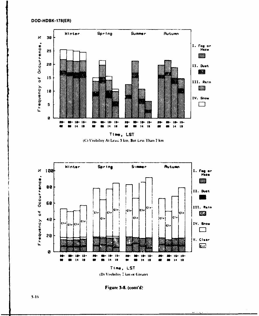
DOD-HDBK-178(ER)
Winter Spring Summer RutumnX? 36
0 1. Fog or0 Hazec 250S,.
28 O Il. Dust
0
o IIT. Rain
o IscC
IV. Snow
iW- - -I - W W - 1- W - ti- - I5- le- 11- IMP- IS-U 1 14 1 U N 0 14 1i N N 14 19 0 0 514 13
Time, LST(C) Visibility At Lai 3 km. But Lxs&s Ihn 7 km
Winter Spring Simmr RutumnI. De or
L ,
U "-"
O2 h I l Ict . '.' -- I llRutnCle Ra lft
0 ,,. Pc c !>. !Ci Cit C ics
SO CIOeIV. snow
c CIO
2* I I Ll
0 V. Cloar
i a- s- Il- 81- a- W is- 10- a- I&- I1- iS- u- li- t-
a U It I m 1 It I, 0 14 i a s I14 Is
Time, LST
IDi, V ;,.b-, Lm tnl o
Figure 3-8. (cont'd
., ~I
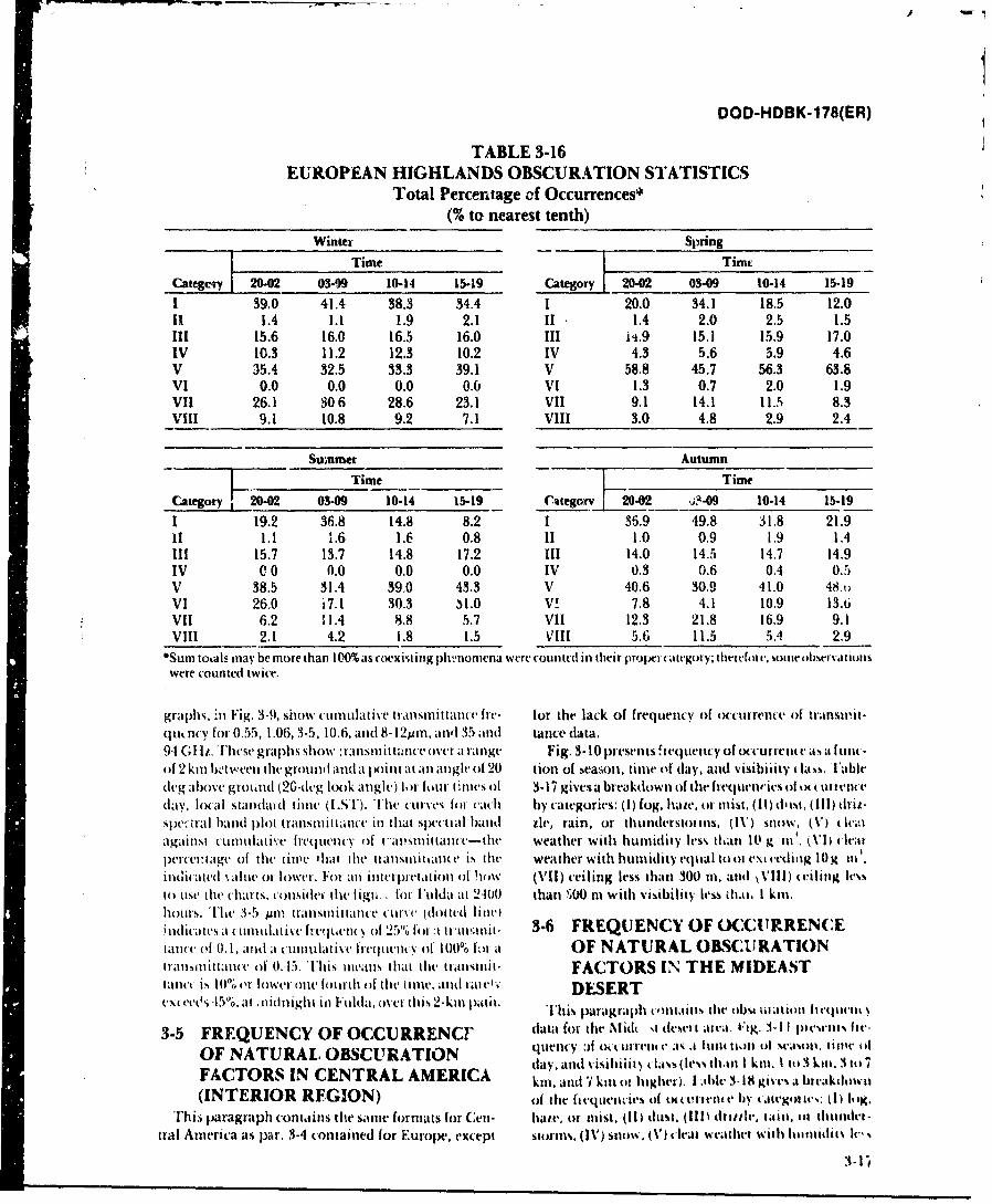
DOD-HDBK-178(ER)
TABLE 3-16EUROPEAN HIGHLANDS OBSCURATION STATISTICS
Total Percentage of Occurrences*(% to nearest tenth)
Winter ~ ______ Spring
Time Timc
Categery 20.02 03-"9 10-14 15.19 Category 120.02 03-09 10-14 15.191 39.0 41.4 38.3 34.4 I 20.0 34.1 18.5 12.0II 1.4 1.1 1.9 2.1 If 1.4 2.0 2.5 1.5111 15.6 16.0 16.5 16.0 111 i'*.9 15.1 15.9 17.0IV 10.3 11.2 12.3 10.2 IV 4.3 5.6 5.9 4.6V 35.4 32.5 33.3 39.1 V 58.8 45.7 56.3 63.8VI 0.0 0.0 0.0 0.6 VI 1.3 0.7 2.0 1.9ViI 26.1 306 28.6 23.1 VII 9.1 14.1 11.5 8.3
-Vill 9.1 10.8 9.2 7.1 Vill 3.0 4.8 2.9 2.4
Sumer Autumn
Time Time
Category 20-02 03-09 10-14 15-19 ('~tegoiv 2-2 ~ O 10-14 15-19
1 19.2 36.8 14.8 8.2 1 35.9 49.8 31.8 21.911 1.1 1.6 1.6 0.8 iI 1.0 0.9 1.9 1.4111 15.7 13.7 14.8 17.2 111 14.0 14.5 14.7 14.9IV 0 0 0.0 0.0 0.0 IV 0.3 0.6 0.4 0.5V 38.5 31.4 39.0 43.3 V 40.6 30.9 41.0 48VI 26.0 i7-1 30.3 31.0 V!7.8 4.1 10.9 13.6VII 6.2 11.4 8.8 5.7 VII 12.3 21.8 16.9 9.1Vill -2.1 4.2 1.8 1.5 kVIII 5.6 11.5 5.4 2.9
0Sum totals mnay be more than 100% as coexist ing plhiiirena were coun ted ini their Prpriutegoi y; therfe[ 1r, So e bsrva Iionlswere counted twice.
graphs, 'in Fig. 3-9, show cumulative tranismittanc Irv- for the lack of frequency of occurrence of transniit-(jtricy for 0.55, 1.06, 3-5, 10.6, andI 8-12Mmn, andI 35 and tance data.94 GI-li. These graphs show transmnittance over a ranlg Fig. 3-.10 preset'ns requertcy of tcurrrtue.' asa flln(-of 2 km twtiveen the grotund and a pitat tnlangle of' 20 tion of heasoit, time of day, and visibility t~ s al(legabIo5' giound (2G-dicg look angle) bor four- tilmes of 3-17 gives a breakdown of the fit-quentics of tx orrenrday, local standaid timec (ISV). 'I'he CttIT'vS for cach by categories: (I) fog, hte, or mlist. (1I) dusIt, (11I) dril.51)pi' )tl an plot transmnit tiatt' ill that specti al bauld tit-, rain, or thne ttis I)snow. (V ) (Ic;%iagainst cuinu111lti'e frequen'cy of t 'al"i'sit taue-the weather Withi humidity less kan I0 g m it. (\,I ( hatlp~ercenttage of tile ltle t hat the tran1silttlnce Is itle weather with humidity etital tool ext vrdiag IOg tin'iflr.ua t(I %aIle o1r lower. Iorl anitltetprttCatiOll Of 111 0w(iIl) ceiling less (hall 300 Ill and V\III) teling les%to uise the ('harts, considei- tilt figti, for- Fuldat at 2-100 than W) i0 mWith v'isibility less khmc. I kml.hoturs. The~ 3-.5 yin trantstitit tan lce tttIW (doit td line 3ittEQ EC)O W UR E Cindicates at (ttnltulative hvjeunv of 25"0 for :t tr,innu- 36 FE U N YO (CIR Ntanc'e of 0.1I, and a cuIIttIat isv frq Ite t'( Of 100% I'l at OF N ATURAL OBSCU RATION
trtmn t autof 0.45. 'This inuauts that tielt tmisiit- FACTORS I NTHEE MIDEASTtnec is ItII% or Ilower onle fottrthl of thle timle. and tae DESERT
exMTeO, -15"0, at . iidight ill IF ulda, as et this 2-kuin patil This paragraph c(mi tims tilt ob%4 Ut atioti hi eitteth s
3-5 FREQUENCY OF OCCURRENCF data for the Ntid %I desci t alva. trig. 1-11 piesents ftv-
OF NATURAL. OBSCURATION ciletncya:f o'retc a.1Ituit tl ol of tst~ tuic 44
FACORSIN ENT AL MERCA day. and visihiiit~ lass (less thain I km. Ito 1 kilt. 3 tol 7FACTO S INCENTR L AM RICA kil, and 7I kill Ill higher). I abhlv 3-18 gives at bucakdowti
(INTERIOR RFGION) Of thle fit-quetli Iv of tt~tett flby aitegeot i's: (Ii 10KgThis paragraph contains the satni formats for (2en- hale, or mist. (I1) dust. (Ill) dtttle, I antl, m* thtiuudet-
tral Amnerica as par. 3-4 contained for Europe, except StIrms111. (1\') snlow. (V') cleat weathect Wilih h11ut0Idt-.
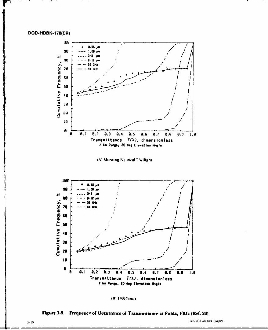
DOD-HDBK-178(ER)
A 0.55 m98 - 06 6m
....... 3- 5 pm0 - - - 6-12 p,
-- 35 G'z-- 94 G
0) A' A
L.5> 4-
a 0. 8.2 0.3 8.4tanc 8.5 8.6 0.7 8.6 8.9 1.8
2 km Ring. 20 des ElevotIops~ ~1
(A) Moraiing NjutiiaI Twilight
Ito
>l4e -.
-- 35 at
U 38 64f
ar 68
>48
S3
l9 .' .. .. ....
3 .1 .? 8.3 8.4 0.5 8.6 3.? 8.8 8.9 1.8Transmittance TW, dimensionless
I ko he", 20 doi CI*valklio gile
(B) (AW n hotari
Figure 3-9. Frequcaacv of Occurrence of Transmittance at Eulda, FRG (Ref. 20)
jiIII .1 1X
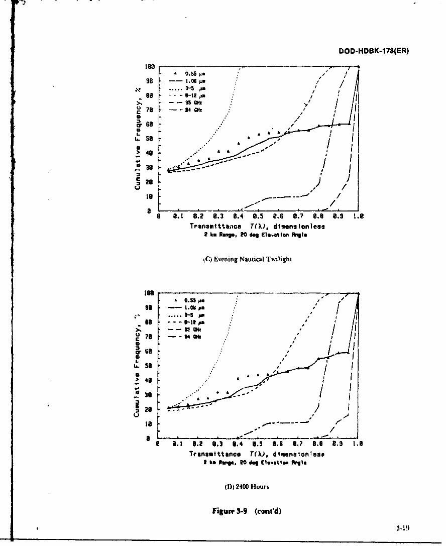
DOD-HDBK-178(ER)
1880
s 1. 6LM98 ---- l~p ,.;/ / jF. . ..... 3-5 # ,, * l
;, -- - ." ' / I;7?B -- - A4 m,
S58 "' Oft
2 28
t- Evening Nautical Twilight
le 0.5554 $A
/I" /1
i .8 --- 04w sel t " -" 'l -ll.
?L --- B -l,
> 49
A */3-j
II -----u- ± I - -.
0.1 .2 9. 3.4 8.5 8.6 .? 8.8 8 . 1.8Trianstttance T(). dtmensionles
I km Ruln, 3o &V £levatip ftqgI
(1)) 2400 Hour
Figure 3-9 (coni'd)
t . 19.
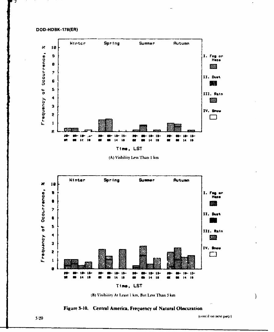
DOD-HDBK-178(ER)
Wirtcr Spring Summer Rutumn
I. Fog orO Haze
L1 o is0
0 1I1I. Rain
-- 3
IV. Sno
IR a 14 to 0 1 14 19 0 M 14 1o O N 14 1o
Time, LST
(A) Visbility Less Than I km
I! nter Spring Summer Rutumn
SS I, U.rq or
! HHU0. M
0 11. mano n
.I) bnk
a 1t1 ( M 14 of aa s
(B) Visbvit AtLatI t u ows-'hn3kF'igue31.CnrlAeia r~unyo aua bcrt1 °2 iml'
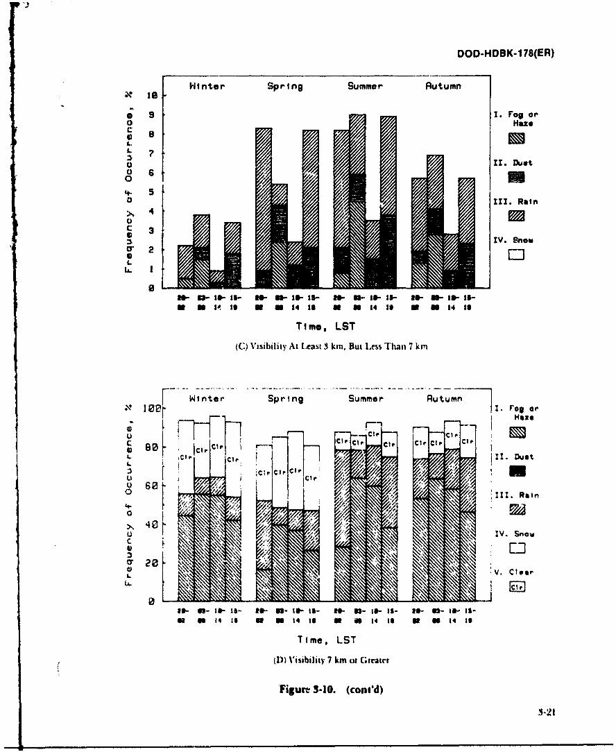
DOD-HDBK-178(ER)
Hinter Spring Summer Autumn
* 9 1. Fog orO Haze
0 8Hsz
0 6
04-" 50 111. Rain>,4
c 3
IV. Snow
2
W1 W iol .s- Ws- 1 1 - s- Is - - as- I- 1s- lm- le- le-U 114 is 14 1 ON 14 1 a 14 to
Time, LST
(C) Visibility At I.east 3 kin. But Less Than 7 km
Winter Spring Summer Au .u mn, 10.B . Fog .r
i Haze
IF C1 P O
) 0 -! --OO
LlV. ClRai
Ze -o s ra- - am :s o - i n- N a- :-;s- Ci-
Time, LST
cl)) isibiliy of ( -itr
FigurL 3-10. (cont'd)
IN2it o- 12-1-ls
11 40 14 is 0 I I4 19 0 i n I 4 to a SO n 4 1 0l~l I l
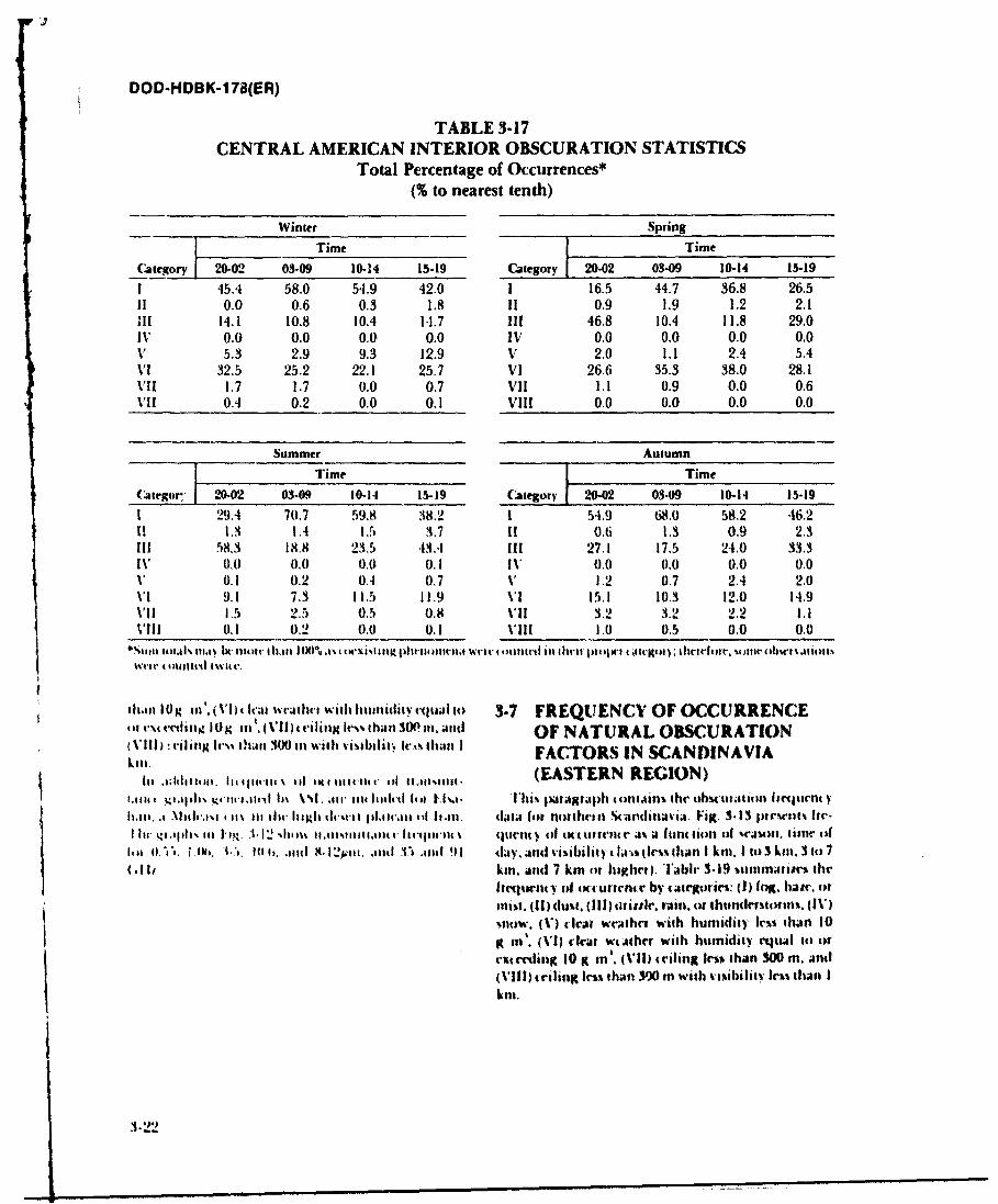
DOD-HDBK-178(ER)
TABLE 3-17CENTRAL AMERICAN INTERIOR OBSCURATION STATISTICS
Total Percentage of Occurrences*(% to nearest tenth)
Winter Spring
[ _ Time Time
(Category 20-02 03-09 10-14 15-19 t
1 45.4 58.0 54.9 42.0 I 16.5 44.7 36.8 26.511 0.0 0.6 0.3 1.8 II 0.9 1.9 1.2 2.1Ill 14.1 10.8 10.4 1-1.7 Ii 46.8 10.4 11.8 29.0IV 0.0 0.0 0.0 0.0 IV 0.0 0.0 0.0 0.0V 5.3 2.9 9.3 12.9 V 2.0 1.1 2.4 5.4VI 32.5 25.2 22.1 25.7 VI 26.6 35.3 38.0 28.1VII 1.7 1.7 0.0 0,7 VII 1.1 0.9 0.0 0.6VI! 04 0.2 0.0 0.1 VIII 0.0 0.0 0.0 0.0
Summer Autumn
Time Time(Caegor;: 20-02 03-09 10-14 15-19 Category 20-02 03-09 10-14 15-19
1 29.4 70,7 59.8 38.2 1 54.9 68,0 58.2 46.211 1.3 1.4 1.5 3.7 11 0.6 1.3 0.9 2.3111 58.3 18.8 23.5 43.4 !11 27.1 17.5 24.0 33.3IV 0.0 0.0 0.0 0.1 IV 0.0 0.0 0.0 0.0V 0.1 0.2 0.4 0.7 V 1.2 0.7 2.4 2.0VI 9.1 7.3 1 1.5 11.9 VI 15.1 10.3 12.0 14.9VII 13 2.5 0.5 0.8 VII 3.2 3.2 2.2 1.1VIII 0.1 0.2 0,0 0.1 VIII 1.0 0.5 0.0 0.0
"Nule tiltaI ni t ti t I hlel I t 0% .t t tdtl hcttil!iil wri t' u 4 0c tlwl m dwit p i eilV3 Cl 11tCihrltmlt. U)fltte ohbwtittills
Wrv 4 "toillit'd *it V'.
hlitani 1ii'. (VI)t hval wcathct with ilunltiattituta it) 3-7 FREQUENCY OF OCCURRENCE, cfV\V tiing10pM l. (VII) 4 iling h% than 300 in anc OF NATURAL OBSCURATION
kVI11 rilin Ic' itan 300 i with vasibii '., tlhan I FACTORS IN SCANDINAVIA
1ii .1hI.01 hsqini \ IMS tin",111tn . (EASTERN REGION)t.,, 1114 i.adt. 1.t' ld h In . jw ia' idt d l.l I'..a. lhi atagfrIlh 4 ) itain,, the obs titatit I it 1ittentIt.411 -i .li1th.1I I It 11 t 111 high dh'tr Il.ma-,ati Ott Ii .sn. dala lot nIotht'sll uIalldilnlvi. Fig. 3.13 Iptrr lnl! fr-
Iw .g.I, iII I' k. 1. 12 ' .111m IfIttilllttidl tr~gtitl filter(V o4f I ) (C tirmi a ar J 1 I(tint 1011 tl Wof ll. timel4 of
11*t it. 1 l. " V 101$. .1t11 8.3 .!stt. .,1d .170 111d 91 d.y. and visibiliy Ia-(hle I han I ki. I it) 3 klt. 3h)7(AIII. kin. and 7 km or higrW). lTabir 3-19 asililiaris"s fil
freqtetly of Mct Ulrrnt v by argoir: (I) log. hatc, Col11st. (11) dut%. (li1) 4i.ttle. r;iin. or thundrrmto1i. (WV)%now. (V) ralat weathr with humidity les than 10
g m. (VI) clrar wiathr with hitmidity vqtual it) to
r(14mling 10 i in'. (VIi) triling Irm than 300 tn. and
(VIII) criling Irs than 300 i with vixibility Icl than I
kIn.
$il
3-.:2
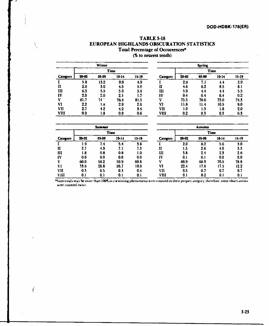
DOD-HDBK-178(ER)
TABLE 3-18EUROPEAN HIGHLANDS OBSCURATION STATISTICS
Total Percentage of Occurrences*T(% to nearest tenth)
Winter Spring] Time ]Time
Category 2h-0 00-09 10-14 15-19
I 5,8 13.2 9.0 4.9 I 2.0 7.1 4.4 2.9II 2.0 3.0 4.5 5.0 11 4.6 6.2 8.5 8.1III 6.3 5.5 5.0 5.4 111 5.9 4.4 4.4 5.5IV 2.0 2.0 2.1 1.7 IV 0.4 0.4 0.4 0.2V 81.7 74 76.4 81.5 V 75.5 70.6 72.0 74.3VI 2.2 1.8 2.9 2.6 VI 11.8 11.4 10.5 9.0VII 2.7 4.2 4.2 3.4 VII 1.0 1.5 1.8 2.0VIII 0.9 1.8 0.9 0.6 VIII 0.2 0.3 0.3 0.3
Summer AutumnTime Time
Category - 0 10-14 15-19 Category 2002 03.09 10-14 15-19
1 1.9 74 5.4 3.8 1 2.0 8.2 5.6 3.011 2.7 4.9 7.1 7.3 11 1.5 2.8 4.0 3.3Ill 1.8 0.8 0.8 1.0 Ill 3.8 2.4 2.3 2.6IV 0.0 0.0 0.0 0.0 IV 0.1 0.1 0.0 0.0V 60.0 58.2 59.9 69.8 V 69.9 68.9 70.5 78.8VI 33.6 28.8 26.7 18.0 VI 22.4 17.6 17.5 12.2Vii 0,3 0.5 0.3 0.4 VII 0.5 0.7 0.7 0.7VIii 0.1 0.1 0.1 0.1 VIII 0.1 0.2 0.1 0.15%tim t*utjk mijt bc nir thjm 100%a is twxitinE phentflirnvl r tluntId in thru proper f Atlwwu)rthvretort, urntn nbwr o11- katweir Ett t w it'r,
(
3-23
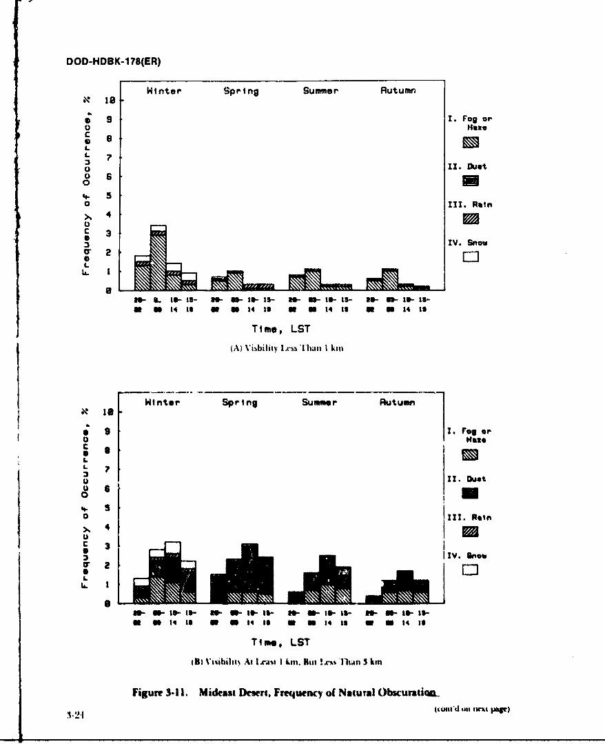
DOD-HDBK-178(ER)
Winter Spring Summer Rutumn
9 1. Fog orU Ho
L
0 11. Duet6 60 M
4-. 5O 11. Rain
c 30IV. Snow
L
0- S. 10- 15- -0- I- 15- W- a- 1o- 15- E- v*- 10- 15-w n 14 to a a 14 is a a 14 is a n 14 to
Time, LST
(A) Visibility LtAsS Tha I kin
Winter Spring Summer Rutumn
9. ?.feo
L
L S70
0 III. Rein
>, 4' I.U
IV. snowcre [2
I.-I :..21o W 3,6 -3- 15- W - -I- No- t- I.-
w a t4 is a a i4 to W 0 14 18 M i 14 10
Time. LST
(B) Vimbilii .t I l ai I kin. Biut !.rils Thali 3 kin
Figure 3-1I Mideast Desert. Frequency of Natual Obscuratioa.(unt'd t twt tpi )
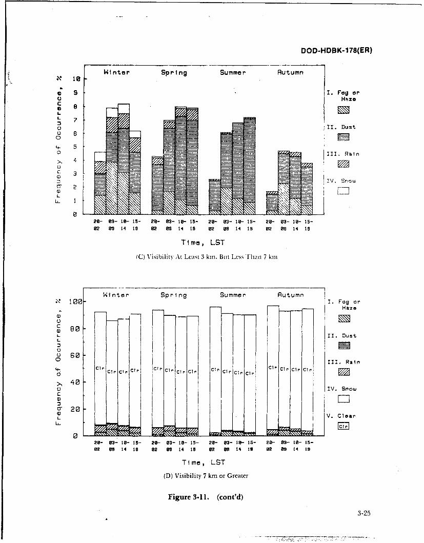
DOD-HDBK-178(ER)
Winter Spring Summer Rutumn
9 I. Fog orO Hnze
LL
0 II. Dust
0 5
0 11I. Rain
IV. Snow01 2-
L
2- 03- 18- 15- 28- 93- 19- t5- 29- 93- 10- 15- 28- 03- 19- 15-
82 89 14 19 92 89 14 19 92 99 14 19 02 9 14 18
Ti me, L.ST
(C) Visibility At Least 3 kin, But Less 'li'hai 7 km
N inter Spring Summer Rutumn*" 10I 0 I. Fog or
Haze
- 80L II. DustL
III. Rainh' C~rCP Cir.Cr Cir CC ,C c, ~ 1 CI!' Cl CIP Cir
L V. Clear
029- 9'3- 18- 15- 28- 83- 19- 15- 29- 93- 19- 15- 29- 83- 19- 15-
82 9 14 19 92Z 8'9 14 19 92 99 14l 19 92 89 14 19
T ime, LST
(D) Visibility 7 km or Greater
Figure 3-11. (cont'd)
3-25
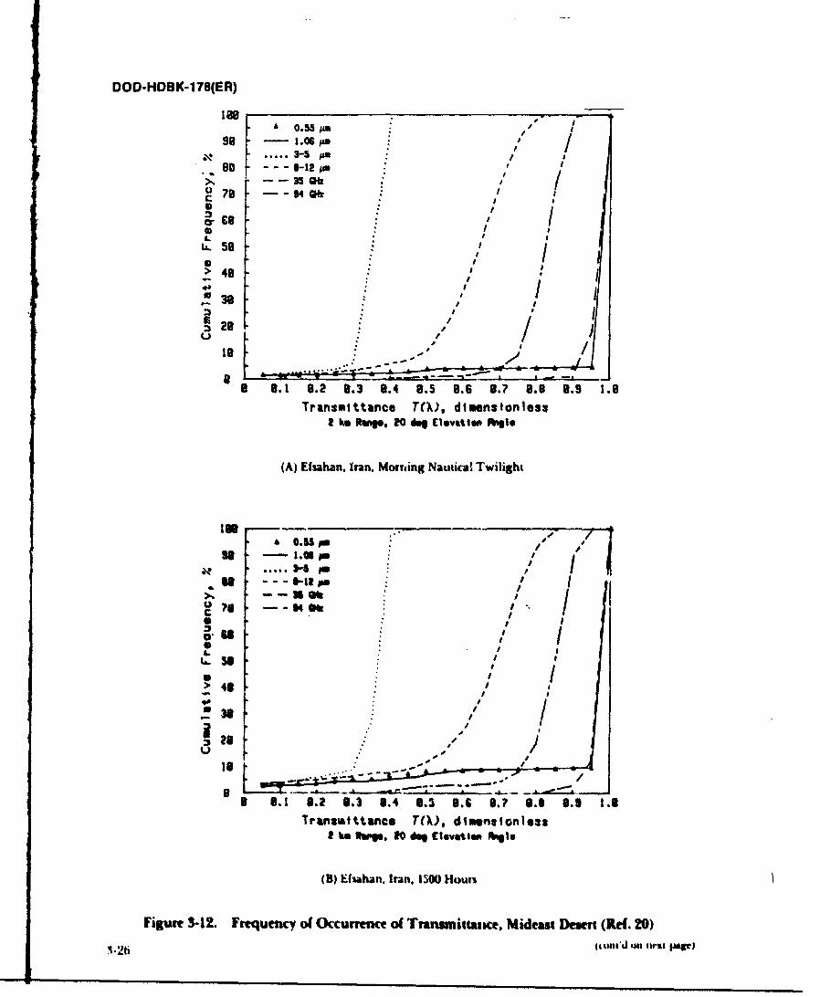
DOD-HDBK-178(ER)
188 --- --- -Ise 0.55 pI
98 1.06 .
S. ...... 3-5 #Me --- 8-12,".
---35 /78 -94
38
" I /
28 20:/ uie1.
8 8.1 8.2 8.3 8.4 8.5 8.6 8.7 8.O 8.9 1.8Transmittance T(.), dimenstonless
2 ke RepO, 20 1 Elevatin higle
(A) Efsahan. Iran, Morning Nautical Twilight
. --- - - -i/A 4.5 I /Pi
..... s-s//
--- *-tape
ID> 413 /
Is--~..-.. -- , o J/
B *.1 8.2 8.3 8.4 S.3 8.6 8.? 8.0 8.9 1.8Transmtttmnce T.) dimnsionless
2I h ftrig. 0 d9 Elevstio kqlo
(B) Ef ahan. Iran. 1300 Houri
Figure 3-12. Frequency of Occurrence of Transmittance. Mideast Desert (Ref. 20)-2 6i (to t'd U41 nW t JP nq )
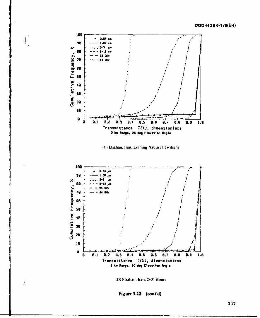
DOD-HDBK-178(ER)
lee -18 ...-js . -/
r so;
99 -1. ; : , .
88 - - -S-lz ,p: .
58J
~?8 --- 4~ / . , I t
> 48
:.9/ /f• /
329
~ 8
8.1 8.2 8.3 8.4 8.5 8.6 a.? 8.9 8.9 1.8
TransmIttance TO,), dimensionless2 ke Rue, 20 fkg levattmn fnglo
(C) Eahan. Iran, Evening Nautical Twilight
a O.S5S :// a
.98 ....- Stm aa In
-- --SQ 47e -- 404, / ' :
68 / i
* 3-
lie L.. / /
"I aft
38-
8 9.1 9.2 0.3 9.4 8.5 9.6 8.? 8.0 0.9 1.8Trr nt ittnce 7(). dimensionless
2kaftan* , 20 a C*vx%1w "to
(D) F2hahan. Iran. 2400 tout%
Figure S-12 (con'd)
3-27
1ir0k 7 / ~~m a
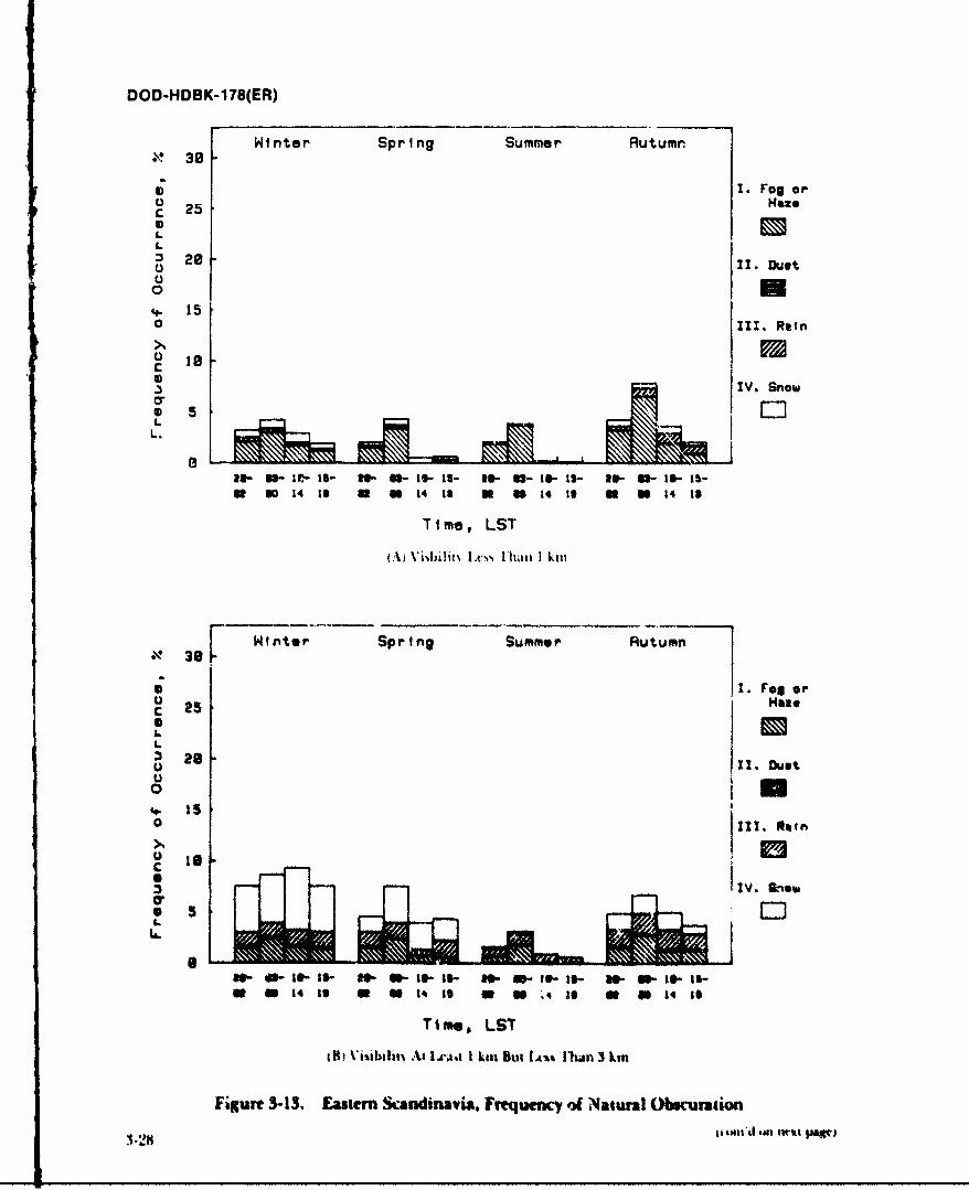
DOD-HDBK-178(ER)
SWinter Spring Summer Rutumn• 30
r I. Fog oro Hazec 25*
:3 28 ins0
04-. 15o I!. Raino
. IV. Snow
OrLL.5
36- -1~- 5- 6- - s- W5 a6- o- is6 - IS- 3-U 6 50 0 14 19 u u 14 11 u U 14 13 U M 14 1S
Time, LST
(A') \'xvie l al lt I kill
[13 Winter Spring Summer Autumn
* I *1. Fog .orSIU
0 n4- 150
8c lIV. Btkow
0,- 0- 6- s- SO-3-16I- I. ISIS- N- n- lo- li-0 U 1413 w tIq I a 0U q I I14 to
Time, LST
dil 'i~mbgllt.At .L.ci I km Slit IA?.l|n 3 km
Figure 3-13. Eastern Scandinavia. Firequeny of Natural Obscuration
i tl'd im .nrit pwt)
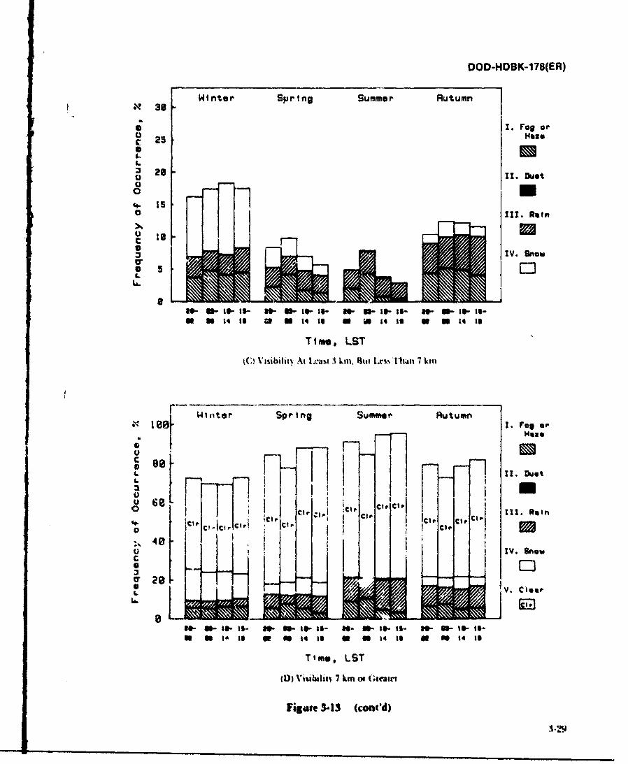
DOD-HOBK-1 78(ER)
X 0 Winter Sping Summer Rutumn
* I. rag or
0
UUc. 10
IV. Snow
05.*. 0
a.- U-Is- W W. a-I s- W. W- le- Is- W- 11- Is- Is-N U 14 It go a 14 to ft W t4 16 a So 14 Is
Time, LST
(C Vilibitv At 1lh*st I kn. %iat Lxsi' *1ivAn 7 kiii
0 to WtiterSprng Sm" , Ruu" . Fog or
~ 0
CO Ill. Rainw41 . 1HI c e C O C 0
ti :: : CIO-T40,LS
(I))~~IV Snowi~ m '(;nlcae33 cnd
V. Close
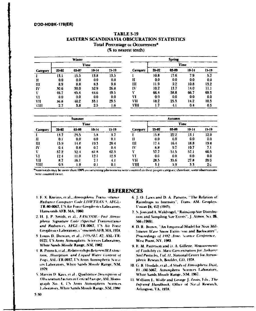
DOD-HDBK-1 78(ER)
TABLE 3-19EASTERN SCANDINAVIA OBSCURATION STATISTICS
Total Percecntage oi Occurrences*(% to nearest tenth)
Winter Spring ______
Tm Time
Category 204 0- 10-14 15-19 .aeor 10-02 03-09 10-14 15-19113.1 15.5 13.8 13.5 1 10.8 17.6 7.9 5.2
11 0.0 0.0 0.0 0.0 11 0.0 0.0 0.0 0.0111 8.9 8.8 8.3 9.8 111 11.9 9.2 10.8 13.2IV 30.6 30.0 S2.9 26.8 it, 10.2 13.7 14.0 11.1V 46.7 45.4 44.6 49.5 V 66.4 58.8 66.7 69.3VI 0.0 0.0 0.0 0.0 vi 0.0 0.0 0.0 0.0viI 3s6.8 40.2 33.1 29.5 VII 18.2 25.3 14.2 10.3VIII 2.7 3.8 2.5 1.6 Vill 1.7 -1.1 0.4 0.3
Summer Autumn
Timor Time
Calegor 26-02 34 10-14 15-19 Category 202 0.9 10-14 IS-19
1 3.7 2!).5 5.8 3.7 1 15.8 21 -2 13.1 12.011 0.1 0.0 0.0 0A1 11 0.0 0.0 0.0 0.0111 15,9 14.9 19.3 N0.4 111 17.A 16.4 18.8 19.8IV, 0.4 0.8 0.7 0.4 [%1 8.0 9.7 10.7 7.3V 5712 S2.4 61 8 621.3 V 57.7 51.5 57.1 60.5VI 12.4 11.0 12.1 12.3 111 0.0 0.0 0.0 0.0VII 0.7 16.1 2.1 4.1 VII 28.5 35.6 27.8 2M.VIII 0.5 1.9 0.1 0.1 VIII I.3 5.9 3.s UA
*%mit itmaJI% irm t, iwr thmai I 0%o% ~t w% ii Ifixpbhsrofm1.4 wtt suitMi i Itrit pI m*'t .ttr~ta .: thrdr. -Aww bwatvatiue
REFERENCES1. F. X~. Knrisv%. ci ;Al.. Atwtuphtena 7'rg', wfento 6. ). 0). Iljw% and1 D. A. Pationyi. -11w Reluti'ni W
vs. Canipwvtrv 4F f.01YTIN -. AFIf~.- Raindtup% it) Inicnsiei'". l'tah. A.M. Gvll%
I'lk40-367. I'S Air Foftv Ue~~~ ~boat. I nitn 24. 4.12 (194 ).Ilanustb AF5. MA, 19010. 7, S.jo~iaMu A. Wal*0 Riuo~svDolu
2. 11, 1, P. Sm-itb. vt ;0. .4.~:w.t .Uenoi. ticn andi anpling %r F.sit*. J. Atmlwia 26.phrni NhInaatdre Ccair i~pna n Ttdowl~naltadfle W6 (196%9.end HReana VI, AFI1 .IR6. I'S Ait F()# 1 ' H. D. R. liton. "An Fmprwal %fkl fin Nrot Mi1-
(.r~.lw ati. 'm~obA'RNt. 978. liwe %kVjAr Snouw .xtim -tm ;knd AmRarkte".
White N.atls Miir Rtkngi. SM. 192, 9. C. N1 t. rcumaMd 0. A. (dileire. Maurements1R. Pinnik.il.. ()I~~%&urILrn.o Visibility 4.iis s -uCottntation jur .Airbotrntio". Absoioan. and laitSr ll'.1#'r Ci.;nVe*1 o4 ,I Sil Poti la's. VI 'ad. 1. taeanat ('Aent 1w Airust-hgIs. ASI' -I.O37. I'S Ativi Airrtpht-if Sh il. pibr Newar.t4 b. Bkukkr. (A). 1978.4M~ 1.a~aw.~ht j'~M~l JK' M 0. G,(. I o.4mal. ri al.. .4 .N ftdvof.4inausphru Mos.u19794 Y( .)M-5W7. AtrnwpnjAw tirnir I~boatorl,
~M.41..in i) tjI.Qu.ele'Wi ai~#E Whie smods Mitmic Kanhtr. N.M. 196' ,(Jb U# ation te 4' 10rin rn; -*I Iste*,~ ANs. SMawt). I L william L, woule andl (IM34r I.hi't. Id.1h~rglajIh No. -1. i' Afnl% ;A11149irvt vWttu'% Infrord 11endbtmoA. 011aar ;4 Naa'm krwranh.I .jniallbsv. Wl'hltr %itulh liawic RanK!'. NM. 19k Arlingion. VA. 1978.
3 N
DOD-HDBK-178(ER)
12. M. B. Richarmson, A (;ener-il A1lgorithm for the 17. William L. Wolfe, Ed., Iland'ook of MilitaryCaiculaiion of Laser Benin Spreading, ASL-TrR- Infrared Technologv, Office of Naval Reseairch,
0116, LIS Army Atmospheric ScecsLbrtrWashington, DC, 1965.Whire Sands Missile Range, NM, 1981. 18. Ralph Shapiro, Solar Radiative Flux Calculations
13. Frederick G. Gebhardt, Development of Turbu- from Standard Surface Mveteorological Observa-lencc Effects Models, Science Applications, Inc., lions, AFGL-TR-82-0039, 11S Air Folce Geophlys-Ann Arbor, Nil, 1980. ics Lab~oratory, fHalscoii AFB, MA, 1982.
14. D. S. Bond and F. P. Henderson, The Conquest of 19. Bruicc Miers, Grosem Worldwide D~ata Base, ITSDarkness, David Sarnoff Research Center, Prince- Artny Atm-ospheltric- Sciences Laboratory, Whiteton, NJ, 1963. Sands Missile Range-. NM, 19841.
15. T. J. V. Schie, Nocturnalillunination and Decrease 20. E. M. D'Arey and E. P. Avaia, Slant Path Athnos.of Contrast in the Atmosphere, TNO, Amnsterdarm, plieric Transmnissian Statistics jor, Visible ThroughNetherlands, '969. Mlillimeter Wavelengths, ASL 'R.0 154, US At i
16. George 0. Lof. eIt al., Tordwide D~istribution of Atnospheric Sciences Laborau iry, White SandsSolar Radiation, Solai Energy Laboratory, U n ivt- Missilet Range, NMV, 1 98-1.sity of Wisconsin, Madison, WI, 1966.
BIBLIOGRAPHY
Meteorology and Cimatology F. x. Klvts et ill., Atinospheriw Tra ns~ntilli meR. F. IluschIke,, tltmosphitru- I'i~sual and iijran-d Franiv ladian e ; unputer (ode LX) lITR.I 5,AE1.
mission IDeducd fromn Surface 11eather ()bseria- FR-80-0067, I'~S Air Forte Gvoph% sis l .botati ii.
tions: lWeathit r and II'ar planes VI1, Rand Corpora- I lanisut )b AFB, MIA. 1980.tion, Santa Monica, CA, 1976. Fail. J M(G :arte, )tu(, o tlt' I tlnmjiderc. Johdn
Marvin ID. Kays, et all., Qualitative lDestription of Oh. ~~i lc &. Sons, Nt-%\ Yotk. N Y. 1976.scuration Fac tors in Central Europe, ASI . Mono- WV .' K NI idllIttom, 1i .% iot Th~r(Jag/ he.tuopir.graph No. 4,1 ITS Army Atmiospherk St icn cs I al)(, ii ('i t\ ~ of 1'Ionto Pt css Fono. (.niatlai, I 9j 2.atory, White Sands Missih( Range-, NNI, 1980. 1. '.- 1~he itra l~miainadIe reaw% ol
R. J. List, Siithiso~'min MleteorologtiIa Tables, Smnit h- Cojt'tot In tit .lo, p/hrie, I No,) Antsisti isontian Institution, Washingtoll, DC, I966 Netliikd, 1969.
George 0. I-of, ct ilt., Worldwvide Distribution of Solar 11 J1. 1. Smlith, tI Ill., F, ISC0l)F,-Fa~t. 11~~~' Itioet
Radiation, Soliar Energy Laboratory, liiiiversity of S14atre C ode (Ste't,011 111111 ,tate n Raed,-Wisconsin, Madison, WI, 1966. a'o e), A F( 1.. Il4 067. U'S Att h ii e(v t it I
Bruce Miers, Geosein Wiorldw'ide D)ata Baser, I TS Army Labi~ an itv. I Iaitinb A El, MI A, 1978.Atinosphc:u it iciu(V Laboratory, Witt1 Sanids NMis- 1), Bit lutit, "A 1)illusloii Nloddt loi .111 ("ballsilt Range, NMI, 198-1. AraA.,mch o lp.t lirn l~v 8-1Fb
Ralph Shapiro, .Solar Radiail'e Flux Cahcu.,tons matuil ly )
from iStanidard.Sur-ft'ue eteorologwl(al .()hYerationi,, Williami L.. Wi die andim (.eotge .1. /.m'si%. Ed" I T&.AFGLI-TIR 82-00,49, 1IS Ai- Force Geophysics I ibori3- InfIraredl lla,,ebook, Offit 4, 141Na.;il Retw-ti Ii. A? lifigtory, H-anstotnh AFB, MIA, 1982. ton, VA, 1978.
William Wolfe, Ed., Hlandb'ok of Militarv Infrared Limite 'isibill, litittle field tondstuo'. I hl It hti.Techno logy, Office of Naval Re-search. Arlington, cal Cooidinnot Gm itti, jo. it Aitu ion ( itltip (J1*G)VA, 1965. 1l() 19.
Optical Propagation Stattus Report oil Linear 11ptnloliemTu Ira Mwn ieisJon,Louis 1). Duncan, et all., EOSAP.. 8-,, ASL.1R-0l 22, Thlt. Tlechlit'.11 ( tottlinatioii Utipi, Joint At tioll
IS Army Atinospherit Sciences Laboratory, White (;i)tlp (JAG),)i, 1977.Sands Missile Range, NM, 1982.
Marvin D. Kays, et al., Qualitatiro D~escription of Ob. rurbuiencescuration Factors in Central Europe, ASI. Motno. Louis 1). Duncanl, vt ill.. b.O.SAlt. 82, ASI.- R-0122,graph No. 4, 1 JS Army, Atmospheric Scient es Labor.- US Arimy Aimosphei it, Stiee [..ab,01M01oY. Whileatorv, White Sands Missile Range, NM, 1980, Sandts M~issile Rangr. NNI, 1982.
i3I
DOD-HDBK-178(ER)
1ircdvrik ( htbuiI, lh' 'clopmu'nt of TurbuhI'me lffr'its Other Relevant Literature,o!rlx, ' i ,t c \ppli(mions. lic., Ann Arbor, MI. G. B. Hoidale, et al., A Study of Atmospheric Dust,1980. ECOM-5067, Atmospheric Sciences Laboratory,
R. F. l.toniiiski. , al., Degradation of Laser Systems Whie Sands Missile Range, NM, 1967.bY Itlmmpleri( ITurbu'me, Rand (orporatioo, AMCP 706-117, Engineering Design Handbook, En-Siati \oni a, (A,. 1973. vironmental Series, Part Three, Induced Environ-
V. I Iaim.ski. T' lI f"tts o) I"u rb u ient Atmosphere on mental Factors, 1976.I Wav, Propagation, Wuac Program tor Scientific Combat Environment Obscuration Handbook (Draft),l~iihllitiOi1s. Jt ,Icuihl, Israel, 1971. Smoke and Aeroscl Working Group, Joint Techni-
William Wolh' ind (,cogt Zissis, Eds., The' Infrared cal Coordination Group Munition Effectiveness,11idbook, Emil miwntal Rescach Institute of Aberdeen Proving Ground, MD, 1984.Mit higan .. nntt \i bmt, Nil. 1978.
e ""
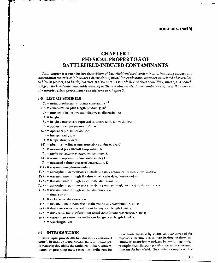
DOD-HDBK-1 78(ER)
CHAPTER 4PHYSICAL PROPERTIES OF
BATTLEFIELD-INDUCED CONTAMINANTSThi's chapter is a quanti.tati.ve descri pti .on of battlef ield-induced contaminant:, including smokes and
otlscuratun materials; it includes a discussion of munition explosions, launcher-associated obsejuration,vehicular fat tors, and battlefield fires. It also conta'is sample illustrations of arti'llery, smocke, and vehicleusage, which indicate reasonable levels of battlefield obscurantIs. These comnbat examples will be used inthe sample system performance calculations in Chapter 5.
4-0 LIST OF SYMBOLSd=index of refraction structure constant, nl-
CL = concentration path length product. g,,!iilDi = number of helicopter rotor dimeters, d i nension less
h. = height, Iihip = height above source expressed in source radii. ienols'
V' apparent radiant intensitN1. k%%* i
01) =optical depth. dlimensionlessr hot spot iadius. Ili
T' teniperaturv, K of6T, plut , enterline trinptatte atbve amlbient, (kgC(
', =Ineas-tarti peAk filelhall trix-valmue. K=P pretdictet! v'otini .ic'.ged teiniatuir. K
6T. sourtir tetti tattite Abov nibwivnt. dex C;
Tv tramntl %oluii aivcagvt1 teubiiic. KTt X) =tralisinittanc e. tiivd inc m
.A A ataitinphell 1131in~~littainc e toni~tkrittg onlN, ;lt uoo :%IiltC (t);). ilv %o)I,
TA; trjllnittant(e 111iough Il1'. tta of %chi( ula. thm. insol%
1'A)tanuit It' 11h4UKh 10141d %110W. ll11li. -IonlvVW
7.A;aliot%jhem IC tallsi)ianIt c I 1(l Ifi I'll, o1; nolet 11Wu ex IiIit n t d illunrnooIv,.%~
TdA) = tAn-viiiiatv 11t0IKttg II tn)LI. ititikV
V, = rld tfic in. danitt'%in~octk,O(A)I = Alb- U1.1111 i11a%%. VX111iit Iiii ! tM1 oiit lt .134jll waIiligtl A. ill:
"4A I (iust mtai'% 4'y(C)(toitl t ovilien till 43n al gi A, In g
m~)=lass rctit Sitl C(()dert fol luem %now (f an *akttgdih A. ill' K
a,(N) = inotke ilia%% ein( tiontt toefit lehnt 141 n wavvirrgth X. Iii gA =Waveleungth.
4-1 INTRODUCTION 't. Ntiitui. 6 A1 illy till asev11.4 li lt,~~iio ii
Tbis chiapui pitwitdes, the bAsi% (fit d1.114l 1UI.4iICNIof I-XIe. Ied At tttiat lot t i.s nt. of inm 1Kti lw thA tn-
b~iu lrfsrldinldvaet C)HJmjjtI Cik I oil ses t- ta lintatitso 1114wbaiked:.ut h% l~i tlpingto4 st1folinaticev by' (lest Ibiig lte btltt'dtt14tiCuam- isipk.r Ilit ltaskiJC j)Cflsahh obi4 11tt.itutil1.41.-
ittat%; bv ptokidiiM ma-.i exihittio (t41 wil((irais foi tlism on5 (the WbItIkI&VId. ISle t' Cbibit rxJiinplv% ui lv
DOD-HDBK-178(ER)
used with thequlantitativeobscurat;on data to calculate engine manifold or by vaporizing fog oil with pyro-obscurant effects on system performance, technic or mechanica! generators. The spectral charac-
Inventory smokes, including phosphorus, hexachlo- teristics of the two oil smokes are similar. The U.S. hasroethanc (11C), and fog oil smokes, are described in par. fog oil generators and uses vehicle engine ext4-2. Brief discussions of developmental smokes and smoke systems (VEESS) lor armored vehicle protect.threat smokes are i: luded, but the data are limited to The Warsaw Pact countries have an er.tensive oil smokekeep the discussion at an unclassified level. Literature generation capability.references to documentation on threat smokes, candi- The most common reactive smokes are chlorosul-(late smokes, and developimeatal smokes are incladed in Ionic acid (FS), vhich produces sulfuric acid smoke,tht bibliography. Par. 4-3 treats munitions explosions and titanium tetrachloride (FM). which produces diluteard includes munition-generated dust and debris, as titanium hydroxide and hydrochloric acid aerosols.well as a discussion of dust cloud temperature and Both are similar to phosphorus in extinction proper-gaseous emissions. Launcher-associated obscuration, ties. The reactive liquids are obsolete ir US inventoriesvehicular factors, and battlefield fires are characterized because they are highly corrosive and dangerous (Ref.il prs. ,-1-4 throtgh .I-6. la'tlfila 4onamlinant usage I).levels are developed ill par. -1-7 by using examples of Representative spectral extinction ocificients ofarIilley e ar .Ilgte-ge'trattl dtlust and tlIris, oisciling these smokes, measured by the I.'S Army Chemicalsmoke, and thi( ula dust Reseawic and Development Center (CRDC), are shown
l1w mass extinl lioln oct i, inis giM ,1 in this laptlr in Fig. 4- I. All of these smokes are effeti ive in the visiblepeimit the ;lh ti t Oil tiou t atstittlain e Ihimagh sn)kt' ;n.! ait less e[1vtive in the inhared (IR). PhosphorousT,(A) and trilnisittillm tl(,\) t i)igh high texl)l)oSiv smokts have tilt highest Ii IR extinctim. None ot(lIf) dust tis %hili ii dttt (T(A) Io hlted snow) thtst snokes is effe(tive at milline'-r wave ulixvl
whIi 11 thie used with the itiolet .ula1 Iti1,n11iutn e ttlin ,avelelgths.
" . ) antid the iet- t osol ift ausuittttu let t I| Ill l',( ) ill F-it. Stn kis t It lendl in l tilt US Arm\ invent' ry inuh"le:j- 1 ip I at( llalt Ialln ll s illilllt c 1,(A) Iph)h()slilt u .s utll nitiolls atd .ie t 'l i. I , C munitions
T( A) =~, F.0~) 7 ' 'A) Ta(A). .0id smloke ints, and log oil 'tit genlutoits. All (if thesed I. l i t (-- ) getii att white ,otitikes. whlt It attenuatt b)y ditiusing t)l
tilt lb • 33 st .uling atliaiti, lhe, ate listo in 'lath- 1-1 with
'AA (1,t 11 li .l'igii stokt's ,id dl-h pnuetital sn )kcs.4-2 SMOKES AND )OBSCU'.RATION I)-velt)ljittuctual siuke,, and thicat ,inokt-, . tli,,-
MATERIAL tissd In nih it int lassilid lttl it |.ais. 1-!. I jlaln
I ic ue lut l et l.i,,hllsslh ht'l u ili&al () " ' . ,., I~ ti~ ''. .ld I't elt- - lrtO it im tl" dt-tailrdiit~iu~lutuoII1 lItl nultig Ihasplii) ~h .1 ili .111. lll ii~lt ii-tlllnlll all pltn ittud.iea hii~ it tijll+silitmt. vil;ot II.ittiiii ,.l,'tl iii annlt'.a. Slj.4 utal tots' e~tinutl t l 4 twI 'ltlentsv lot fog oil. dit'.
tit o I t it otl s .a ll tfi c difI i.tJiw t , it .il - i I rit t u id R ' l t, Iil. liln a d lu iu s . I I-I I an d . tlii %" air ti llke , .tiw
Ii. l'haaspIlnt1 ut)1 s to t vl s .I " m It a id l it s liumonig I heit . it 1 ..llhh I.2. I lhe tnh t;i d .,lli.s.i I iut"
ittl I-. I t I tI t I m l iN li u) t fui~itt'., hi, II 1,, 1 ,) nt. . . h.. .Iit hil t I .111% .,tm.i 4 ,!
,I ItNt i t 14 u tlilll it , Itilti .14q-iit' ,,l I ti lt l tt,-
..11 id, and 1 111 i. 1 krii t; as hulk.-flltt410 41h ellt Isp, It t i %VIVI. 116,11 it-itv lI IIId I it) 111) t * 1 1 41,o
fit%. lph, ftiit d im \Vlitts l1% Rt . )an . .1 P t it su.- ).., ki.l......
ttltiiitimns., I Il" aallt Ial l 11itt, 1 tI tut' h ll ks .11t' lnht i ,l i Rui. 1 I t. 1 I tilt-N li Ilie lt tu v pIll iphlau. ' "
flil '4.. o| litalt I { I dt r 4111114 -1 11 1 h111 11C. .lll 111 f.itl- iI IlI-s ' iit-l' l t l
l '11it I is at4l. g lt- i * e ittd n1 tit tn i l l a 4 .h t, ll, it, Ilil I.t+iell t l pix iiia n aI ltL~ , iil , h t-as Iltiij ,, sut ,imv
Illi- A. t ll t t .Ill l t " att & ,i 'I t i ' I I t . % Cl. , ts It i1%. , - -ittu l iii, t I . .
]X) +lll~~~~~~~lllIM'lif o+~at k\ # ,l ,i I a~ltll" I~a li"ll.).l m + +
,l 1. 1 i i t bi l l a l i b st i fi l- r t eam il hiuR I . C 1 1 o f(t ltht-4atni w ,.. -tl afni.. 11 , hlv I'llkr Figure -t-1. Mwas Exti.t ti1e Ctirl'lit iesilot4 , itg I hrt awl iti a-tin %lattil I dirm- tml ,I) u stldatllt S rlritilg lroko. (Refs. I andcl. 2')e u 1.nd-a- s .',s1i -a -- te saa 1 L .- ~-
DOD-HDBK-178(ER)
TABLE 4-1. INVENTORY AND DEVELOPMENTAL SMOKES(Refs. 2 and 3)
FILL WEIGHT, BURN DURATION, EFFICIENCY,__ _ MUlNITION kg s %
155-mm HG ,. it3 projeiite 8.61 100 70105-mm HC M84A1 p;lojectile 2.15 120 70Smoke pot, HC M5 14.06 900 7081-mm WP M375A2 0.73 45 1004.2-in. WP M328A1 3.70 45 100155-mm WP M110E2 7.09 60 100155-mm WP M825 7.45 720 77105-m WP M60A2 1.74 75 10060-m WP M302AI 0.34 45 1004.2-in, PWP M328A1 3.70 180 605-in. PWP Zuni NIk4 6.15 180 60Oil generator, M3A3 151.2 1 h 900 1002.75-in. WP rocket M 156 0.96 120 -LSAI RP 0.36 100 -Gtenade, hand M8 0.55 120 -Smoke px)t, SGFZ, M7 5.91 600 -VEESS M60 181.It 1 h N AVEESS Mi 317.5 i h N A
Developmeptal Items
81-11) XN1819 1:17 300XM76 grenade -Oil gtner itor. X,%52 227 IIi N A
Foreign Munition*
155.trim WP pr-jet tilt" 7.01 126 1(M122-. 11132n1i1 WP pltr tilt. 3..f)9 80 I00l2t)-mm WP plojetlilt. 1.95, !) I 10082.111 WP poirt tile 0.3-1 17 IW)122-mn PWP ptojt' tilt V.19 180 1M
TABLE 4-2. COMPARISON OF SPE(TRAL MASS% EXTINCTION (:OEFFICIL TS O(A)(Rds. 3 a. id 4)
t s Etlil l lt{lliaN gnil(Aw tl og .4A . lit g
0.4 Io 0.7 io 35 G;li0 ___urn _ 0.7 1.2 1.06 . to I 11 12 10.6 94 (3l6
F(% Oil tits .59 3'.1" 0.25 0.02 1.02 0.O01
Diewl Oil b,65 4.08 3.25 0.25 0.02 0.03 0.001'*Phcsph,,us t.0 1.77 1.57 X0. 0A$ 0.538 0.0010I; :9 66 2.67 2.218 0 19 0.03 9U,0 0.0010
Anthrt rie 6.twi 3.50 2.00 0.23 0.06 .05 0.0010
4-3
DOD-HDBK-178(ER)
relative humidity at 10C. The hygroscopic smokes, and burn time for standard phosphorus munitions aree.g.. WP and 11C. show some dependence on relative given in Table 4-1.humidity due to x)th change in refractive index and tile Phosphorus smoke particles grow rapidly: they pullchange in particle size as (roplets take up water from moisture from the air and dilute the acid concentration.the air. Th change in extinction coefficient of WP and The particle size, refractive index, and mass extinctioniC( with itclatite itniditN is discussed in pars. 4-2.1 coefficient change as this happenis. The expected sizeof
and -1-2.2. phosphorus aerosol particles depends on the atmos-Transnittnant,. T, (A) though simoke is calculated pheiic relative humidity (RH). Theeffective extinction
from ite t'int lion tllitiu'lt aB(X) and tile L prtIKl- (oefficient and yield factor of WPsmokeasa function ofltct of obs( Illant: relative humidity is shown in Table 4-3.
T,(X) = c-,l (T. dinitc sionless 0-2) WP cloud temperature vs time for a bulk-filled 155-r-m projectile is given in Table 4-4. The right column
where gives predicted average cloud temperature in neutralCI. --ronceittitaIion l|t h length priluct. g i z atmospheric conditions developed using the Electro-
u,(X) =sinok e mass xtii(tion (Odfficient for aiv Optical Systems Atmospheric Effects Librarywam'-le'mgth A. in2 g. (EOSAEL) lode (Ref. 3). The measured peak cloud
snlokt tltt tlhtti isdimt ussted in pars. 1-2.1 thtough tetnperature and average cloud temperature data are1.2.3; t cilu r.ts;itt (-.. txltiits oflsmo~ke, may lx, dest I. shownt in the left and center columns, respectively.
iil'l hoimlithc t onihat usage levels in pal. 1-7. I, These temperature dilfrentes within tilt cloud appearas t iultel or fake targets When viewed through thernal
4-2. PHOPHORS SM KESImaging systemls.4-2. PHOSPORUS SMOKES isdillicul t preditt tilt level of phospliorus snoke
istpilomtvs smoke i. hitoluled b hult nilg elenetal to x' eXpected i n a hattlel eldenviIolnmell. lll alountphohot Ikt us in air. I hI 'thates Iaill It hit n a phtIs. of plo)ho us stoke in t stnenor lineof sight depends
phiol it at id avrtosicl. I h hil tittg phoslllhot ts is et % on oniany fit tots i 1 luding the atinospheric t onditiots.hi i it viualI: tit. sloke i adiallt tt ilo i palelllit tilt plat lnent tf tilt noke dlative to tilt nom. titI litdi I iltIago .Pilu )IllIts t I,IItokes t I It t'l ell I I tiN.ntt t )l sti ttki plated, and the frequenty with
tIsetI tst't liendl% ix, ititll , lIt.tusc eel thl an gt-I hotu 'hu h it is pIlat et. hndit ations ll tt'astnabhe IrvVls othe hill. it uling phi lltltus .41.0 the .1t40s1 tt it W11 at' dvhrilopd in tilt- tmke usage illutratiot ilsituikc'. lpnt. -1-72, the" WPt til nnttionI path length plot lt a
ihun plit\ It t 1)111t1, , ll. ,Uld lut theI tult. (taliev t six Intlk-lilled 155-111tntm uilititl., %htlwn tintlg atoitl I i'tc's tjUt ki, l'F.isit int's Klt" phlti uK, 'ig. 1.2. ndit ites a Ipit Il sAApe lot tile WP tonteittA.
piosluht , it t im l igt t-ilh lt wedgte", .ltu dted chtu tie!\tin t titme Mt tosA a tuline of Night (IA), howingihtt it ti tt stt.ltitul ;litt' tlt'stg hilltt t I t nlltii" slow I a tlal ll huildujp. then a gt.tlual fallofl Is thiet lout is
.111d ,tilh ititli'ae rd htlt tltiitftt its, fIlhlitl weight Ihlown ,past. luliulrntt ill g i'lt tk and lotal %hilt ti)
TABLE 4-3. VIELi) FACTOR AND MASS EXTINCTION COEFFICIENT FORWP SMOKE AS A FUNCIION OF RELATIVE HUMIDITY
(Re. 5)
Walenitith ,A. Am
Iield Fm tot 1,.* 0.4 t0 0.70 IN ,I' (ll:
RI. % dinmcnitulnh" .' 1.2 1.06 1 Its 5 t o 12 10.6 94 (All
3.39 2.94 I.T,0 I.31 0.26 UO. 0.35 0.001t) 3.51 2.94 1.!1 [I 0.2 3h1- 0214i 0.00 1
30 3.91 1,76 1.60 1 .26 0.33 0.318 021 .0.001.) r1.11I .0$ 1.77 1.'7 0. 2 02.38 0.1 0.00170 5. 10 .. 11) 2.03 l.ti 0. .9% _% 025 0.00190 7.X)5 3.23.1 2.i 2.11 0*II 0.V) 0.21 0.00195 11,70 2.9"1 2. Iti 2.2!v 0.A 0.27 0626 0.001
*N tral I.,t it i I dlme it w l itkii " .2\'ntttsaId liit', *. .ihi
DOD-HDBK-178(ER)
TABLE 4-4. WP CLOUD TEMPERATURE vs TIME (155-mm BULK-FILLEDPROJECTILE) UNDER NEUTRAL ATMOSPHERIC CONDITIONS
(Refs. 5 and 6)
Measu. Predicted*
Time Peak Fireball Volume Averaged Volume Averagedt, s Temperature Ty, K Temperature Ts., K ~ Temperature 7'p, K
0 N450 336 3392 413-424 327-330 3205 377-388 318-321 303
10 314-323 297-300 29515 305-310 294-296 29420 300-301 292-293 293
*EOSAEL. dust mtdel (kititions: hmfllpel titut, lI6.9,C. 5090 IR 11, l'astoill C.autgol C. winld 3.1 tit S4
issi ikile scretiner ill lit- thierni.tl batnds. and ineflvuiivc at miniv1115-so il Wpawti wavevii lits.
4-2.2 HEXA(:HLOROETHANE (HQ)I C stvo~ke IS dk p)'Iott tIi( Situike gUIR-Matedb i t'
bt il-itg oltW Iti If(: t oillpsitioll ot ;liliiit uiti /ill(
i t%til hulg lI~gttb-t o i( av*losl. I IC: btailtiuas slowklthll l~tisilltiu andt 1ls'ases altit ome-Ilitlth dw
4. ~thi'illad ensltIgy IWI ti late; tilts it rises lvss alld i% lit~ dkipawl dvquitLl llt.vamitdatu 11I I ill~tol is tilt
I M-nu, t tlle >*dei~ edMil 6111 lotld wdl .1 lilt?fe 1, wtuIgtt of l4. it kg .1nd a bill it hun ita If R10 %.
Figure -1-2. lntegraletl Wil Smouke (umn- lii tal Iloudi tdialvt'i. r 1%r.41c ae ciuia1h ltt
tralion vs Time (Rf ,Ikitalt fllt If IC: uuitillu. C lllv inl If( %i( lTimvRn. ~tmilittioun wilt ir I t lev guhenuill 111,11 wttlh WI,
i id sVlKX Ifti diftt lt §11 Will I MA ' 1,1114 It" AIl IM ~ ~ o .v bill lit,\ .mv illilill. 1 lit: %itki. \teltd tat filltuaatuomt ill dwe toit eiit loll .411d t-w, ilm l titn .wttut ant. a% (tutu. isoll tat dta sl
WI, P vilot a IN .1 glclIviia v egu .1a 11,1iinal .uundt ate v~Auit i d I~ i
TABLE 4-5. YIELD FACTOR AND MASS EXTINCTION COEFFICIENT FORHC SMOKE AS A FUNCTION OF RELATIVE HUMIDITV
_____ _____(Re(. 5)
Nh uu lli ht ( "effi irtt ,(A 1. Itt x
Yiel Fatica I .,' 0.144" 0.7 to AN (liRif.' dimrnvionleua 0.1 1 -2 1.06 I to.%i It to 12 10.6 94(all
r) 139 2.76 1.11s7 -. 10 0.17 0.01 0.0,j 0A0110. 1.16 3,00 1.117 l..*W6 W 19 0.02 002 0.00130 1.39 3,(A) 2.1-1 2.01 0.21 0.03 0.03 0.001.50 I189 1.66 2 - 7 2. 214 0. 19 0.03 0.01 0.001to 2.40 3.1$4 2.5 7 2-281 0.19 0.03 0l. 0001
W5.72 2. 1 iu, 2.11I 2.0.1 0.27 0.1 0.0$1 0.00195 10.49 Im) I 9M4 1.93 11.31 0.07 0.W ~ 11,011
t dlat lilt 1% 4ls8M tawv~ nt 41 I&A
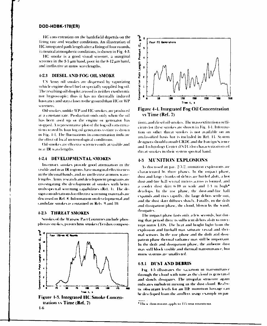
DOD-HDBK-1 78(ER)
It (011 c entration oil tltt battlefield depends onl the __________________________
lirinug lilte- and weather conditions. An illustration of F our FO Getweratorit
I IC integrated path length alter a firing of four rounds,i~i neutral atopei o~iinis shown itt Fig. 4-3. ,
If(: smoke is a good visuial screenier, at marginal a
s(Cee lin thet 3-5 Mim band, poor in the 8-12 Aim band, Cand inelfeuive at nimw waseleiigths.
4-2.3 DIESEL AND FOG OIL SMOKEV'S Vrims oil stmokes ait' dipne by aporiitig
welid l tg int diesel mld or spet tally suppl ied1 fog oil. Iht' I t'stilt intg o~il drop~let aerosol is neiliter. eithernit(
ltl'gi ()Iit: tHIM it has no0 dIet tllI indkuced c -
huo dlt~ ilt 5d'5 IOt othit' glo ud thanl I IIC 01 W1 a so inOi 1itok's 2itlk 2I' ati 33(sitt.aelu0tuti iue -I ertdFo i ocnrto
li11 t 1stati att. Pt stint l ion vilds onl wvsheni lhte oii vs Tim e (Ref. 7)has bct'at wwt tipl of t(lie' engine. (r genet atot hasstolti.&A Itolstestttatist. plot ol the Ilog oil (t natia- (it-ils lot dtese smokes alte shown Ini Fig. -1-I1. 11lnai-lionl t atudet b\ louti log oil Rutt'atouis t5 lit is sit()\\ i Mill on otl iliteat smoke4s is niot atsailal)ie ont an
in ig I-. he in tutiltsit tott itatioat imlii titnt 1,tssil it'd Imsis but i. lilt luded in Rel. 1 1. Ss steiw lti ti ()I likal Iit -o(stlog it at tItttiiiS deat.~ is s~ lltld ontli~t(: )C it tht, I'oieigu'' 11111utt,
()I lit. i~vicls lthat\is6It 'kld and Ic t 1i lim\g ( .utitt Fs IC (tlt t halat lIailsits oli14.1t I R is as el gtls. t1ti1'am siitkt's m tilt-it S\AVtitI spit (1i11lmb nd.
4-2.4 I)EVELOP\IENTAL S,\OKES -1-3 mt'NvTION EXPLOSIONSItist'iito, s stttke piilet gtxxl attetiutitou Int thu .\% th tassel tit pat, 2-12 mitititttbi mvl'l l
liiths'tit uta btis. ut .ti Imw mlis ii ilict if icts usatlbg *Ik\ i thi tb il it* ltd .tlolt pawo
titlltiI~stitI~ trnag ~ .pailmws i-I t. li tlt dssloss. lil tiMla ilti. alt tIo 1%Itied lill
tllso tissIl in R t 4 n a taii itti l Itilt- I Ntt l ..e imilt- l t ski t tIi. I 0 is t midus 1-3tu I l t lit d i.tttultilI,m si.ls %1e w i ng sau ta i ll i s . i c. Itt , I It c (ttol"tliss l it itilt- ilti '. tilt -snd I twt id-tlt is ititi
%Il t . -Ii- OfEA I.. isltins a-1- IsisA It lllk 1 II jt* V lsl w 144 t utuds. bitt slit,domis l i kt's 8, i 104 'sr sit t ( Aiiiiu1 tt it's1 1 li 111 h 1u1' 1111ds lhr thi. i ll hi ti imi% lit1.1k tu l iis lit il t- ittill
tplitilt sts sill o . I.( toelIit s1Ato I u shots 9.111d 1 t114 tijit itt i st a IA ). Ih i'. dwt t ..atd . 10it lih b tltant
I li 11tiht I I a s t li .I I% wntl ils' iil twilt hi ls
41 w1c/Ifl' 111%lo 41 Ami( the1ml.1 t alt1m LOtSl tlisstl l ilt .1d c t11 lts .iga1 hIuti ti c s1 1 ittv.ts st11il 11151 ihl o'tltlt-111lw s.411.l1 tii ait lu l. itt
10.1% % il Iliti ii' tli 10 4 mil t tll tt i iisltatiiss
. - ~ hulls . Wi t~tiliu114 tt-tgi alit- utuasm s l11o 11. 1t ct.!sU M U f U lfl SW illiii s h it-t 4 s lot ',il 111 .4% alit uI n im at a% .t,44'1 d
I1N' low1% 11114-'i liscaiii .ss~ t u als %11144 iiii .1t11
Irj~is~ ~~ 1i~n 14141714 l.11v% toim 111114,11s .111\111K m~ l uist- thim I tid140%
to I siUI111.i 41 141 (-11 o 11 l .1
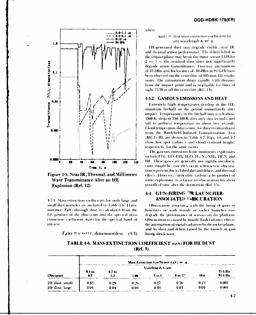
DOD-HDBK*178(ER)
- - - 3.4-4. 1 SU (Ak) dust iilass cxti lio(n01 (4 I i( icii jlot 16-12 AN9 4 aft MN, wivviigth X. in- g.
and thetinal scilsoi pciioiiaticc. 'I'l( dch)i's IdJitd inI i the i Il1)c(' p)hase mayd bicak lie- inum scnsol LOS I:o,,* ~~2 to~ I s: thle icsidlU dust does not signi ichai
I dtglade ic t111 ransini Itaine. IYwo-way at ten nat toils
.~ ~. ~ f of 10 ulBii and( hiua( it tei of -10 (IBi at 94 (dIt ham,......... I etil 4)hscttv't il the (cdilt'iI i 1W of 15-mm11 HIE cxp)I-
1 1 .~~~~ NioIns. The atiation d t o psiOJN ipiI m th klistal)(V 1 flinun tiulIIl(t point1 anid is inegligile lot linc., of
A.' - ~ sight 15-20 in oli the enlterliuie (Rdf. 131.
I /'. I 4-3.2 GASEOUS EMISSIONS AND HEAT
ExtiintIN ighit-mwiatur deelop iii tilt- IIE-m iti o n~h . I iti challt tilt jib t e li i t i ii -i i ateh titi
91500,.) o to 350--100 K afici onI%( k~ ondcs. aid
16 falto the 1bailleIli-li e il abltoil iiiawtoiiletst
I' It :.~'(RIC F) Ill. ate showii inl Table 1,7. Figs. 1-6i and 1-7I Ishow hot S51)) ltdiuts I and (loud (cetioid hevight.
sm~ j li Itiule(1) CO.. O (. 114):, II:, N,-. NIL4 . IiCN,mandU N 46 s so tu ie u 11F. [hwgase ae gt a il 1141i sigini ant tilis it-
I i ilns sitni lw1 mw (tiitu I )4 t- tllt.11 (it-ll staiit thelT i .
Fiitire -1-5. Near IR. Thrmnal. and NiIliiiwter dit~.Ii~rvslliiii talbohl..1 Ih5 .1)4tkit~ ofi
Wave Transmittance After an IHE soun-c v\ldpI lls,1.1 1aI. li hi *m oilt 11.it io in l %lithi
E~xplosion (Ref. 12) MIt lso i 1114 11 i i11c dii. htl.il11 it alu. I.1).
4.4 (dN-FIR IG -M LAUN:ILIER-
1.7.1 Niassimi iati it xiii, it-n%it ,i hiIni-mutt ASSO( IATI'I I I .)( :1URA110N%111.111 (tiis Imli t Ivs .ii lilt mIll t in 1 .1a)i 1 -is. 1 1.111%. Rim~ 111.tlihul .1551) iAn... 4,6 it1 lilt- lit tog caof gtills hit
11113t1 1a' A A t hi t aigli dtis 1% .a.tct 114111 thu1 hcawvli,1 sliat %%ith tin islic tit ilxkqii I.41411. ~lls1C.1, l;tp~1 oxiiIil dir ii 41)5 .1111 miid 1. IN,i s 111 111.1%% dirg t il tic xm-l III)IIf.11ti oi M) 1 41 ist il tail ti piaicl in.
i-s lit lt iMll hlit tv.k ti t thr s,)i-ilia lt l i )s hti ni af ~ tuuiIlih .. n ic
il~hitNI Ihr mitrtl114Olla lh %iitiml I .ilillt II m6 tht lII let 14111111.,
Altl 6s iltisi .11tini11 ibmw i aInttb ill- latimi Ii gtlV.4 ) r.~j'I ~ daurs,.ks~(I 3) ling %stx L. tkasi
TABLE 4-6. MASS% EXTINCTIJON COEFFI(:IENT aAAi FOR HIE DU1ST(Rd. 3)
Me"u Elioitiim (jw'liim l "AA). m: ot
0.4 to 0.7 its V ('110(Miwulani 0.7 Lob A. to 4) a to e :1 10.b 94 (.1111
I I E dull. %ttitll 0 S:! 0I29 1) .Ib W 27 ). 26 0 L1 "P)IWoo
I It. 4uisi. lsg-0.0I 0.041 0.011 0.01 0.01 0.04 I
4.-7
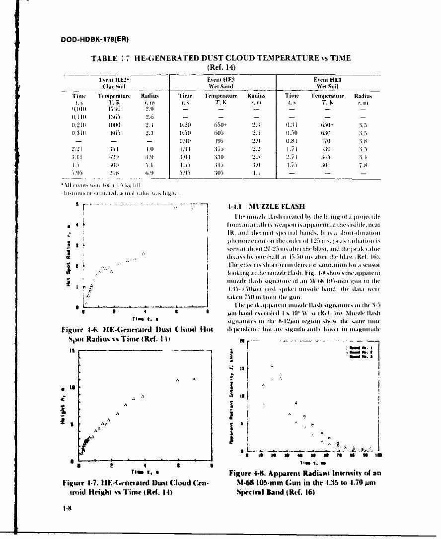
DOD-HDBK-178(ER)
TABLE:;.- HE-GENERATED DUST CLOUD TEMPERATURE vs TIME(Ref. 14)
Event HE2* Event IIE3 Eveunt HE9(:la% soil Wel Sand Wect Soil
11111 TemiPerature Radius Time Tem peratutre Radius Time Temperature Radiust.s T, K ri III T, K r. Ills T, K r, n
0.010 17,AO 2.9)---
0.110 1365 2.6 - - - - - -
0.210 1000 2.1I 0.20 6i50+ 2.3 0.3 1 650+ .50.310 865 2.3 0.50 60.,) 2.6 0.50) 630 3.5
- - - 0.90 195) 2.9 0.81I 170 3.831."1 31 1.0 1.91 .375, 2.2 1.71 130 3.5
.11 129 3.9 .3.0 1 3.30 2.5 2.71 3 315 .3. 1
Lo . ..) :)00 3.0 1.5 301 7.829 695.5 305) 1.1 -- -
5 4-4.1 MIZZLE FLASH
*41114)111 .111,1 .ttilc[ '.%C.IP0 i% d1pI)Bt-lt In dIh ksiblv. Butt
3 j)liummicit mi ~ tt I tif lt it-i (i 12,1 01% pual, t.Bthi.IBOI i- '.tVii .11 .bhti 20-257 itii..li tilt, hI.,kt.m ti lt lit al w ,i l ~uv
L Ill d , .4 I S Il i I- I t l -I d li A it % t tIlat to llj % t It .MA I.
thy ltii ic %Iltll 1 -i 101ii Fvig. 1.8 %ditdabIivapi %iIi)
. ,ui 1, 01 IIB il lmilhur ola un M-ta8 I9-),1111 in i l i ll tity113.7- 1,7t0pill tilk %Iallkc t111%%l Itmgid: til 11.1t.1 wvIc
I 1 .s1ril 750 lit litoutit' gu..... .. ..... I'i f l xxk *I11ah iIl ot ui,,It I11 NI. R~ignatt io' i tilt 3 71
3 34 6Jimt 111-111141 VM~ i-thtt I N. l0' W %11 1 ' X . Ili). NIu01t 11.1101
iguKre 1-6i. lit.~-(;rierated D~ust (Cloud I1i0t dIhi-wittl-ns 111.1 hutv Ille BgiIu*BI o-Bit nt..uiuS,wt Radiuxi vs Time (Red. 11
". %
fta
A
3 A
I Is mS a 4S 1111 To 7 to
Ia4 6 1 ieI.aTime 1, Figure 4-8. Appirent Radiant; If1lhitsitv of an
Figurv 1-7. IIE-Grratd Damn loud (en. N.49 105-min Gun in the ..35 it) .1.70 pilfloid Hleight vs Time (Ref. 1 1) Spedrtral Band (Ref. 16)
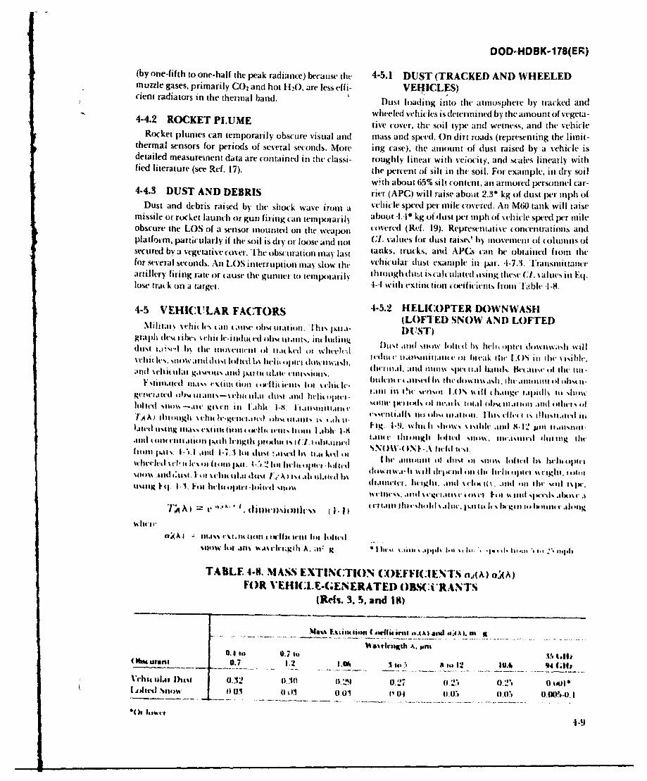
DOD' HDBK-178(ER)(by one-fifth to one-half the peak radiance) because the 4-5.1 DUST (TRACKED AND WHEELEDmuzzle gases, primarily CO 2 and hot H20, are less effi- VEHICLES)cient radiators in the thermial band. Dust loading into the atmosphere by tracked and
4-4. ROCET PUMEwheeled vehicles is deter inined by the amnount of vege'ta-4-4.2 OCKET LUME ive cover, the soil type and wetniess, and the vehicle
Rocket plumes can temporarily obscure visual andl miass atil speed. On dirt roads (representing the limit-thermal sensors for periods of several seconds. More ing case'), the aniount of (lust raised by a vehicle isdetailed measurement data are contained in the (lassi- roughly linear with veiocity, andi scales linearly withfied literature (see Ref. 17). the per-cent of silt lin tht soil. For example, inl dry soil
with about 65% silt contentl, anl armored personnel car-4-4.3 DUST AND DEBRIS rier (APC) will raise about 2.3' kg of (lust per mnph ofDust and debris rai-ied by the shock wave ironi a vehiicle spived pe'r mnile covered. Ani M60) tank will raise
missile or rocket launch or gun firing can temporarily about -. 4' kg of (Ilust per mnph of vehicle speed per mileobscure the LOS of a sensor mounted onl the weapon covered (Ref. 19). Represt-ntative concentrations andplatfoi in, particularly if the soil is dry-) or loose and not (J. values for (lust raist\ by iniovememi of coliuns ofsecured bv a vegetative cover. The obscuration mnay last tanks, trucks, an~d APGs can be obtained front thefor several seconds. Ani LOS interruption may slow thte vehicular (lust examnple inl par. -1-7.3. Transitil utartillery firing rate or caust, the gunner to terlarl) through (ltvai is talt ulatt't tlsiitI these C.1. values inl li.
losetia k il ataret.-1-4 with extinc tion ( oeilicients fron Fable -1-8.
4-5 VEHICULAR FACTORS 4-5.2 HELICOPTER DO WN WASH(LOFTED SNOW AND LOFTEDNfi itato vet'u Ie.. tall taus' obs4 Wdi I toll1. IlltiN pat .1- DUST)'[
gralh cles libe.,thtl'iiue ohst ur1ani. ii u hdill thlI .tid %lss littit t b% hlittptt'i) dowiissl wIlldustit sl It% th Ilmioviki Ill tt,1(ked (It wlievcz ltttl( (tmlti int Ill hmek the LOS( M% ith le isbsilit t Is. t 1i dItus t i tll 6% lielIt h tptei tt 11% ,li liti sh 11 t. 111, and 11111w ,IN- it.,lbd1 x l kt W (ust. At thc lit.tn IV Iit Itlit g.tsvieus I.li pAt 111It kI I (111it - % et Islt II S. b l-i ia sdh it o .i% 1 1 it 1111ltIlo %pFii'a6111vt tb mi i-lt til i dusl t ..l i t itit ~t-t tm.gt~itl nltet sitte t~tIieiei.tdein
loted itt~sii' ~ts'tii~ Ijih I~V li.n'itii~ite n' inseill s it tli eitn LO Ni lw sIll l p tlt ti n - .hoI.~~~~~u jl it iit'llgh it-Ii 111.11-t~ie list)t 111dtit othr % Iiiu'ii ug mass t't tit int Lii w It i-Kt, I ittat I tlt-11 V~ vl'a . II l. i lit t s I hl t % int -4 I I% 11 l.ui i ct es it
.tit t~t; ntl.iie i ilt I l i Ii jttttitt i 11)t ( 1 ttitetini iis 14(t. iluenligh i ltlt sntus, IIit.1sitilt-1 iltii ug liht,
h n I~ %tci I Iv t . I I o t M I ll .li r I it sq oiu . l 1 AI ll t . lit1 t in l l i I is tu % tt %si 1e t i lt d i v l I n s l i i t i t i
sit ts ti ~ u t I e lt nlm ins ,~i l ea Its iluatuetei Is iti il di. wild til lic it -l.iitl111. oi l lit it l W(n1.tt1ivs 1(1.ht .41't. I.et.n w .1114 tiptt' lile ti it-t 'n
Wtiiie's. .1 itt 5 glt 5 t ni Iti i %inl Wths .cltos t
I.A ti lie) -.i ttIIo I lltttt i hi %si alt v m lane it It'-l. t l11its 10 Ittlt v-at n
11.% I'm. il t' l I'c114 4-llc t - It1
snI0W lt) .11ni U.in a lt- lh A. ;t' R. k it' .u~ epn i i ir *'~ it'le, 1#1 ' 111 Iti
TABILE 4-8. MAM. EXTINC(TION. (:OEFicINi's n.,(A) n;4A)FOR VEHICLE.(;ENERATED OWL Ci'IANTS
(Refs. 3. 5. and 1$)
%%arkit~h A. tonhMM0.11 . ii7~ ~(ual0.7 I2 l0t in 0. LrRi l 1 .211 9(
hodvdiet 0.01 0 OIP01 (t1.071, U.L~ t.0)o. I
-1-9
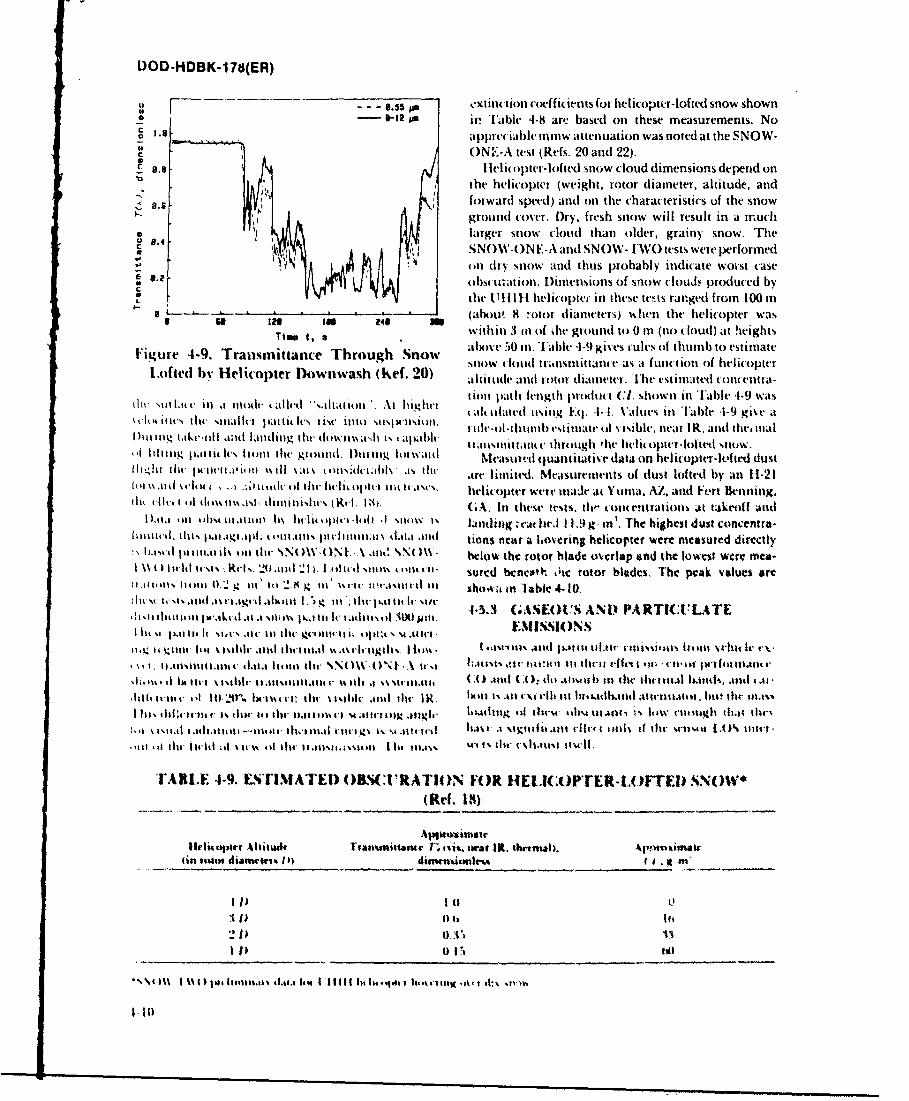
DOD-HDBK-1 78(ER)
a. - 5 - a extinction coelfi(ients (or lielIicopter- lofted snow shown-8-12 in Table 4-M art! based on these measurements. No
~ .8appre(iable 11m1W attcrnuation was noted at the SNOW-c ON.I-A test (Refs. 20 and 22).
8.8 leii(iopler-loftedl snow cloud dimensions depend onU the helicopter (weight, rotor diameter, altitude, and
I Iforwardl speed) and on the characteristics of the snowground cover. Dry, fresh snow will result in a mruchlarger snow clood than older, grainy snow. Trhe
p8.4 SNOW-ON E-A and SNOW- IWO tests were performed(in dtry sniow and thus probably indicate woi-st case
.? obst u'ai I . [Dimensions of snow clouds produced bythet I'll Itll helicopteir in these tests ranged from 100 in
12 U 4 (abts' 8 rotor diarneter~i) us hen the helicopter wasTI In 24 within 3 111i of het ground it) 0 in (no cloud) at heights
Figure 4-9. Transmittance Through Snow aIhO(116t 50 in. 'Fabl -1-9 g I es. tules of thumb to estimate[A)tedsnow t loudl tri'tistnittat t as a fuat ion of helicopter
Lotd vHelicopter Downwash (14C. 20) alfittide and rotor diamleter. Ieestlimated coticentra-itI Nollatii ill a stiodIt talerd "Sallatioa" At highits t ion path Iength produict C1. shown in '[able 41-9 wits
Ncl~iiicstit, illllu p lli lu Iisvillo sisX-1SIM . alt illated tosing Fit -11-1. Value% lin 'Fable 4-9 giVe aIt t I It tIn ina hi i~I lt Is I1s thtt 5151itlsiti I tilte-i-Iliuh11ll) estilitalt. til \isihlv, netat 1k. and the' 1 wal
Iii ii g tke-e I iadLiiilit 14 ht e i~ his al dl.IIUt d1%illittoit, throtigh 'lie hetljo ptl-loitedlow.lilt tuilg palit Irs hiook tdw gltilhl 1)Iaull i tili WI~ Measurvil quantitative data on helicopter-kItted dust
h-OdiiIh nit. I'Ii l)1 %tiltt 'tis1ti %l .1% dt arr limited. Measurements of dust lofted by an H1-21It iiSt .id ecli it .t _1 i t IIIc lit'lt 01liti Ih. itiseM' hielit opter wete wnale at Y urna. AZ. and Fc'rt Bennitig.tilt (li Hut I i~ s diliksiltes (Rtd. I "0, GA. IIn these trsts. tll- (o)m0e!)trations. it takeoff and
D,11)ti o 'll i~b illi s 1 11 % lt lt iilte*l t.1 Nilim. 1 % is laudiJ1K C lIII .9 g sit'. The highest dust concentra-lijim1 thiIs jul.II .111;I iititiali1% I 1li101% 1.1 l'i andit tions near ;I hovering helicopter were nicasured directly
!,btwd Il imnai il\ till ile %INo'()\,) 1--\ ,tilt! SNM - blow the rotor blade oserlap and the lowest were mea-I \\ ( )lteh li tsts Rcts. 2t1.id l i. 1 olti itkv t5 tit vii surcd benciolh kie rotor bladcs, The peak values aret1t ll s 1 il ll.'2 g Ill' iti 2.8 14 Ill wraii i ictti I l tl shntieal in ahe 4-10.
*h~~~~~~~it4-. GASEOUS1xkd 1 tsi't i~lt eitlisdt~t il ANDt P.ARTtIL.ATE'hI ibiitillo its h se.is .1 \WD the. 4it Ite' I.i. l ~.i~pi. BUSMI( NNlh,1 p. 11111,14i %I. ai I~.ll [hr qi,.l sel int i ts-*11 1s n isie iariils.iish ls ihtI s
* tl.I ~tlsliiil~t41i.11.1 11"11 thnir %\( )W )\ 'A It. melol ~ ui~~ Ill tw fin-t-fet ;it- IN-1i liet MuuAW r
'li I i -n I s I tt ~ t' bt a lls t e il t v %,k ill$ .1 \ t'l n A ~ t h e h Ri.' ai. 1 s ll io i t~ t~d a ilt a t e i t tt bI t t t hi . 1 4 .1.5l1 1 1it m 41 s l e l s .t Ie l- i e11% u l 1 t h u t ko t l h i lt~ ~ ~ , h it a d iti g I ' i r m t w it lis 1 1 t tut i d 4 0 1 1' (1 ti i l. t il l! ille t h u sl tl i t , 1 1 1i . 1 1 1 J \ #11i1a i Iu t t- i ll 1a .11 im % 4 1 4 is u i u i i - t t r . ij it i h r m .1 1 1 1A I ; , e f f i 14 6w at ii- m it h t h.m1 1 11 1 -N
*,l tl lu liid -itt d \1-% lt i lIt-i .iilsis. sstlm I lit, Iliss% -1I S t 1 0 sl.1kot stusell
J4TARLE 4-9~ . r1T u ATLI) OBSC( RATIO N FO R HEICk: PTER-1U JFTE!) SNO W(Ref. Mi)
Appoitsurr111rhqrir s Aptcitiif I'anttl~lsur 17 tiii. twat 11K. th~mal). 4onns
lilt itsouh dianwwcltdn sea I ji m7
lt 6) If
W It)1
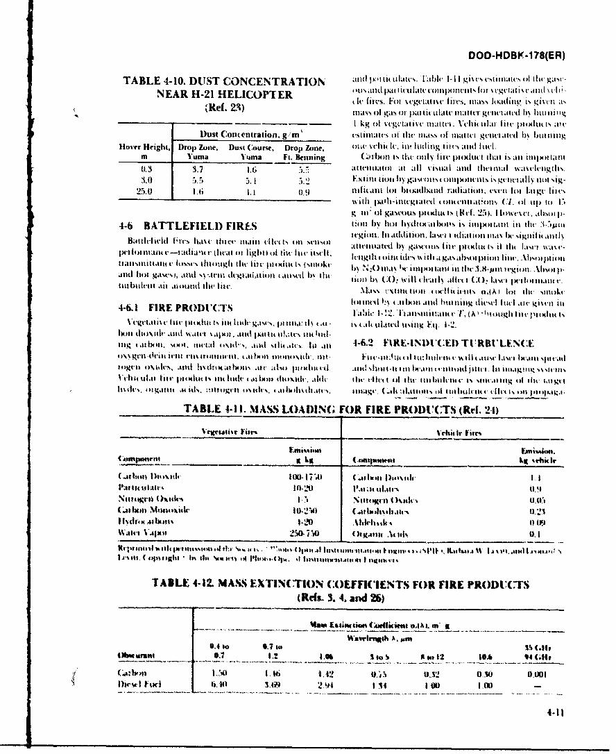
DOD-HDBK-178(ER)
T'ABLE 4-10. DUSTI CO~NCENTRATION ,itd i'tt(l3Imit~..311 -lg~sttlht, ) a 2I
N EAR H7-21 H1EL.IOPT ER '3 3(1l.ti litttI XItts ) t-td S3.31 -
(Ref.Z3) t- furs. Fhl %ctgct-tt ics t-I. ass loading Is gio 331 'Is(Ref. 23)ol gas of palti lit l altu i- gcncwialt-t hN I III hiiiz I I
r.- I kg ofl w-g -iatilc mti. VctIi tilaiIn llt ptiti Is xc1D)ust Concentration, g/m I stlinlaiws ()I tilt, Itass of1 Illaltc13 gt13v3 attl I) blmunig
Hover Height. Drop Zone. Dust Course, Drop Zone. 3)I. Vhi Ie. ill, Ititlitng tlt's anid h id-.mn Vumna VThma Ft. Senning (.pihtil Is ti~tv olhI hic p)(tlttc tat is all ntlipo I 11a)
(1.3 3*7 Ii; .tiltitlatot al 1311 Sistlad an a ti 1133 i).s wa~cl31)gt his.0.3i~ 3.7) 11.3 6)3 J.:;
25.0 t 1.6 .. 0.9 tIlllitIll 10 blo ht(htllht Iatiaio31, (,%-t 13)3 ldlgt- lilt",with )a~l)i~i~tgtatttI 30it3'3tiotnts (C1. ofi 131 .) 1
g ft- ol gasctus pitlut ts, ( Icl. 25). 1 Itawttt . abs)50 p-
4-6 BATTLEFIELD) FIRES 1:011l) 1)0 I hot.[IN I thllioas is ililIll~t il Ihc 1) 3 -7)AI~k
BaitIs- ucl (~t~sha~vtlter ain i li t #m 31)3)3 at ttiitatt'i hN I gast-o its 1ilt- Im~tItt s it lilt l.isttI wa3*~ 133 3t.Lh~ t .t a (liut*l-at of light &d tilt lilt, itscl . It-nighl (m It " idt- ith ia gas absofon 1) lint'. AbI)5t j 11)3
It tts~t~t~ln lw- tA t lgI tfill' if(t I)Itit Is (%mo3 kv b%~ Nz() Ilav 'kIxt It tatill ill tlt 3.8 -M33li It-iol333. .bl)%) pI
aitotg.awsl, iatld s*t(It -gl .t3lil ai d b tilt setl 3.)3 CO w:02 t31 kIca ailv( I ( A), aw 1.353 lt 1313.131t V,1ill l~tll~lt tit a.ioiittt tilt, fit-.. Mass tCth11 3)3in3 33311 I lts a,(A 1loi ulkV Stit kt-
4-6 1 F R E R O D C T Slottticti I'V 4.31)3)3) aittl huiltt 313 tilcm-I flt-Il . )4t'33t) ill4-l. IR POD'( rsI:ItV!)k h. Iltsillitai)3 lT, (A' ' 111otighi lilclttl(
Vet amt.t s lilt, pilt Ktlt i 33 It131C 4 .3 PI 1 33).C i1\ .3al Is. t lilt t)ilatt-I tiin Vl 1-2.14tlio t\1t13l .111d1 wa5lt-t .4)3)3. .33)311pal lit tt.t kit( kuill-Ing3 1.1113311. seit I. littul omd't-s,.nt -il .3'lit alli 4-6.2 F 1RE-tNDUC (E1 Tt!RRt' LFN(1:5)\%g lt ic.1a 31t i t tt~15llitt t,*3I l lIt ious a~ticlilt- 1-t it- t 3 t-d tin: 1)3313 -A ill (1114 ut - I I wtttl spa d~tot)34 ll 3) .lv. md h tlita ein'f. al-tul a 1 333 11tt. Mt! shI I u lit 33)lk-.4,, 1-13111 jilit-. Ill 1astag!, 334 .% '3W-t1V01143 11111t ir p oti I s 1 lilt ltkult t 44 1)5)11 413314 1 1. iic A lit t f-i isl tilt- ililtital c 1 %isialing ti l t 113 3,3134
olgal. tit.3)3 mtk Ml )h)134t) I\I il .3 li bsitla , Iltulg4., (-.1 lsi i I333 i t3 hluhn 3 I. Ilit 1ill 313 111 di...
TABLE 4-1 I. MASS LOADING FOR FIRE PROI)1CTrS (Rdf. 2-4)
( .. aholl I'sth 100). I 7.1 C; rnIastl
Nift -I04 d- 11441 1-21 !%1-.t tflafr% 0.~tls11,
I IJ tb ta3 %43 lI Xik 10 -1)li dt 1) ii.
(Refs- 3. 4. and 26)
M, altimmeae Co4ignt wa;h. ow it
Mkrms0.7 1. .9 1Sit t~o12 106 11 CiCA.. 1.2 1Totl 010I 0,001
Dieu. -I fuc t. 6,4i) 3.64 2 94 1 11 1 00I it
4-11
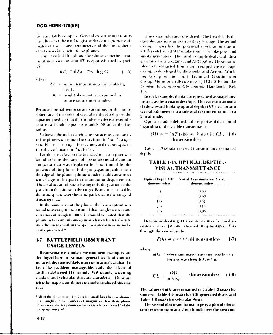
DOD-HDBK-1 78(ER)
6lw~ lh ~t to 6 lt o1'.c of' iag iu (4 l-) I III l it'. tilato ( i .tt 14( I a I ts ]ckt bandagti. II l monandII,. (silspi- it cx tlp k ics tic iii t nta 44ihI~i~
li is ff l 11.1 pIIin ii oclil o m m li n d c l
I oi~ a 14 cii~ai tc ph14~idllcIII( 4..44 ll( i~1 4iliii ilt. .11111- t144wcgicl4.ifl-hls. I'llc 4)114di tvilipt dva)) w .1 ih .It~
pciti 41 1ht thltit am i i 6tsilLili 41jd-it 7tiIklllth'. 4114 .1po iac h\ti (Riti (2)catdb t it'i.llo int-
1441~~vvmpc iiiopc ,iit. tit Sivokc and Actiio lii4/..14 itii u-i
.1114144Ing1 ilioit of thc joi)Ill 441ilia Cood)l ,4 IlionII ,. 14 S
III' ~ ~ ~ ~ ~ ~ ~ ~ ~ ~ ~ ~ ~ iu *44 4 1'.i Mllilk il1. 414 itJ4l1414!ll-t imt-i,*iot E u tcicss 1t111 ; ME fil t
i i t ,414 .1. 441gh tllt i) .so lt Ir 14.111 jII41 *.*i p i-cia-i%-1a s
%I41)4 )4.44 44 I M I, I M' 11-1.441111s11! .4)(1- c'4* it)i dev(4) lo .ii 41',l.ii.t ol tIll
11)1)1 a 4 I st I 1 it 1 )I 1441.14144 Ill'i I' tutl1 Ili I~iii II) It \'' ill' I'll44 )I It)1 m % Ill41)11 illI4 -~ .114'41.p 4* litc II ( of 4 d w 111)11) i, 44 1 4.44111i4%I ) I k4 1)1( i t 114 4 1 14 d1Kg t.,14 th r1 )14 (2 4 %) ) i l t It
Ut4-i I l sigiI% ') M M-%1 tilt, tit o11)4)4)141 o ti lt 1 % i~ib) .114 1 1% il tv
Va)444.1)l.4I 444hc44 4kq(\olOlll I it II4I %tt1 1,I %.I M~' .11 ' M t4Int 1* 011 s)J ~ t).IiI % 141) U ,cll W-6l
'I -it gur I ii II %14) 4ltlid11 4t 4.I i tl ,i ti II I IIIM it 1 ~ I ng A. It
1411(44141*4111 1 AMC-l -144 .1 441.94111.114 %11111 1%11 k M144tklv% itlAi\t.11114ii. of41411114 1I ) ti) ll ~r Ill- ))% 41 iht 4.44
hot114I dr Ica41 t I 14444t,1tit-bl de' il4111 1 t t \I ' Ij ih -'int~ . (184111411d .t.)1141 iI ilt' 1i.t 4111 .1 il4~1'I irjt I~3~
tn, Itl 1.jh '11 i ll141 1004 4 1I11111 MI)il .i 4111411.111T B E -- 3 P I A E T111.4 1".1 th11w1vi ij1 w 44 tit I 11 1 4 I$\1 11 t lil 'S I jblT -A N a4
I bll .1 ItI t .11.til, 441til'-' t hu i $ Iss b*1:11I.4 4 .)1tJ Iabr1. 0A) t111t~ 4~i li)..1
li tig i.41ll4 ~ I4414v pit i 1 ,,,.,litit, .*~ IL4 l.ittiw- Ibq II tlA IW '1g i~ 141
%%il .111.6v litd 1.41 j4 11 it1, hr .1111 %.)li 1I11 . .41 Iltlw I i tth t))4 4)III1.41 441J I~tiisl Utn its J j)14)4 ltioi )1)4
4112 w loilitlI~
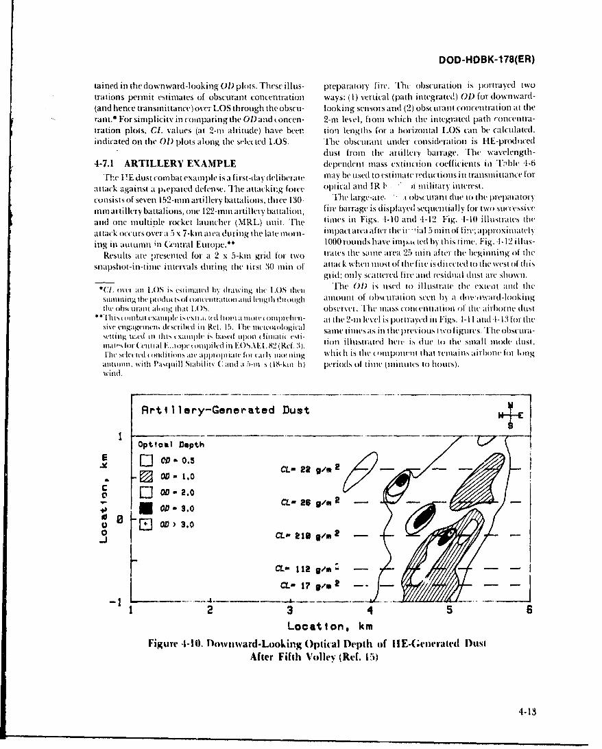
DOD-HDBK-178(ER)
tamned in the downward-looking oi) plots. rihesc ill us- preparatory fire. Tht obSCUratioti is portrayed twotrations permit estimates of obscurant conlcentration ways: (1) vertical (path initegrated) OD) for downward-(and hence transmrittance) over LOS through the obscu- looking sensors andl (2) obscurant concentration at therant.* For simplicity in comparing the OD1 and .oncen- 2-mn level, from which thle integrated path roncentra-tration plots, C1. valuies (at 2-mn altitude) have been tion lengths [or at horizontal LOS (.anl be Calculated.indicated onl the OD) plots along the sele( ted LOS. irhe o1)scuiarit under consideration is FIE-prodi iced
dust from the artilIlery barrage. The wavelength -4-7.1 ARTILLERY EXAMPLE dependent mass extiincion coefficients in 'Eible '1-6
The I !E dlust comba t exam iple is a first-day deliberate may he used to estimai~te r(luc itionisini tranismittance for
attack against a p~epared defense. The attacking force( optical and IR 1, ' military interest.consists of seven 152-nmarti llery' battalions, three 130- The large-are. I obscurant due to (lt- preparatory
nim artillery battalions, one 12,2-ii artillery bIattatlioni, fire barrage is displayed sequeially for two successive
andl one multiole rocket launcher (MRL) unit. Thel tiaies in Figs. 4- 10 and 4- 12 Fig. -4-10 illustrates the
attack occurs over a 5 x 7-kin area during thle late morn- impact area after the ii ial 5 miin of fire; ap;)roxiiiiatlyI
ing ill amuumn ill Central Europe.** 1000 rotinds have iinpak tedl by) this time. Fig. 1- 12 ill us-
Results are p)resented for at 2 x 5-km grid for two trates the samne area 25 minl after thec beginning oif lie
snapshot-in-timec intervals (luring hel( lirst 30 mil of attack when most of t hefire isd(i rected to the( wvest of'thi sgridl; only scatterecd fir ind residi ial (luist are shown.
*C1. owlr all LOS35I is lil Ir. drawinig ili LOS diil lTe 01) is uised to illutstrawt the ('xteot and thlesullmmum g il 1w rduLidso (i iwll tii ial loll iiid lenigil b i!i o ugh amiounlt of obs iraiio( ) stemi b~y it dowi, twaild - I ok in gihv obstil mral along ithat LOS. obsvirver. l'tmass coiteniration (A thec airborne dust
"''lsomubat cxmmil iscmxiaik (d huomia ilowolt ipJ-cli- atl the 2-i level is portrayed iii F'igs. -I-IlI aiid I- 13 for thecsise~~~~~~~~~ Inavnn d.cie nRlI. 1 mwwoi samne ti nies ats in t he previous I ',(! f igurecs.T'he obscurl a-
%eliiig u1:.ed ill ilis ( xamnji is bascd lipxui (liumath( cst tion illustrated herev is dute to ilie sma~ll ilode dlust,mai's loi (Ceimal E.opc onipiled in lIOSAIEt82 (Ref. ).[h I'llc ie(d ( oidiliojis illc appropi iale loil l ineo 11 which is the couponeii that remlainls al-ir o)b longdliimill, %viiii lPdsquiill sililiIN C .11( lii s (18-kinl 11) periods of lilivn (mniiiu1tes to hours).wvind.
Artil1lery-Generated Dust
OptIomI Depth
E OD -D.0.5
XD . CL- 22 9/m 2 6 K...C' E 002.0CL- 26 9 /m 2 --
EOD' 3.0003. CL 218g/m 2
CL*-112ga/m
__4g"m -- ---
12 3456
Location, kmFigure -1.IwnadLoigCpklDpho EGnrt us
4-13
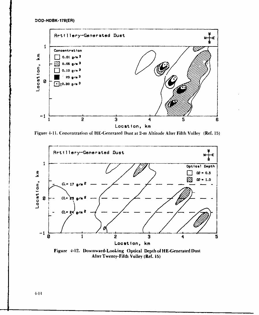
DOD-HDBK-178(ER)
AR-til1lery-Generated Dust+
ConcentratitonLI0.01 Sg,m 3
* 0. 05 g
o j ~0. 10 C/M 3
E]!j~J0.30 g/m 3
2 3 4 5 6Location, km
Figure 4-11. Concentration of HE-(;eierated Dust at 2-rn Altitude After Fifth Volley (Ref. 15)
R-til1lery-Generated Dust+
Optical Depth
0 .
0 05 0 t~ /m
10 12 3 45
Location, km
Figure 4-12. IDow nward- Looking Optical Depth of HE-G;enerated DustAfter Twenty-Fifth Volley (Ref. 15)
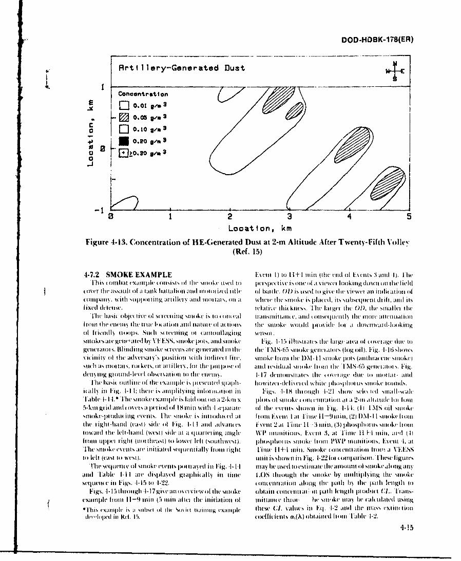
DOD-HDBK-178(ER)
Artillery-Generated Dust
Canoentrot ton7)
[]0. 01 0"m a- 0.05 9/m 3
0 0
0 E]!0j~.30 9/03
0 12 3 4 5Location, km
Figure 4-13. Concentration off HE-Generated Dust at 2-rn Altitude After Twenty-Fifth Voile'(Ref. 15)
4-7.2 SMOKE EXAM PLE Event 1) to 11±1 m tin (Il( he nd of B-cents 3 and 1). Flt.
tover. thc assaltl of at tank blattatliont attll Il00 i/ed Ititlec ofl at. 01) Is ttstl t) give III( v'itwet all ittuluatioll of('0tflIIV'. with sttppottling al tilt' Nmd mnot tat s, oil ia wtwe thet smoke. is plat((I, its sutlsettent Ili ilt, antd itsI ixeti tteltISe. reclat. I hjtkilss. , Ill larger tilt 0)), lile slltc O1w
Thet Ihsit olhjctive 01 mitreetitg sttokt is to ott titi trattsillittam ec, andt mnscelcettl lit-e mlote attelltaiott
fromn lilt, enittiledi truloatit. htm tlid Inattili 4) o tilits thet smtoke woutldl Ipovitlt tot it d4)wtwattl04kiligo1 flikvudI t1001S. Stt( I s(tT~tittg 0I(it tiiiOttllagiltg SCenSO]
stit~ks ae gtteatth y ' I' I.S, lto~k jlts.ati smke Fig. 4-1,5 illstrate-stihe Iatgt ateao (Itovetagco.du togelittetaors. IIIdig n~e5ttt~.t gnr t ilt lit-e INIS-65 sititktgeit atm' s (tog oil). Fig. I- I~ sttows%I( ilt(it O tlversiry's positu)11 wsitht itttlittt I lirt'. smoke frott tlie htI- I I stitkc pots (anittmtute Stttokej.1111 its tlta S, Iott kets, o1 ait illi . t ot thec pill po)st. ItI mid itsitlttt sttokc Itm otitltt UNS-b6 gtmt'dois. Fig.
I'1i ha~sit )tttiilic ofI the( txamlple is icstltttt giaph- Ilowit/tt-dehivelt d white. plosphon us Sttoke totitls.h(AIN itt Fig. 1-I I: thelt is ampl~)ifying infiot itiotl ill Figs. 1-18 tttaugl 1-21 shtow sclc ted sttall-stalc
haitI-I'ihe stiokeexample is lat otit tt at 2-kut x Ilosa toe()1 ttaii 1 t2t llttt lo it5-kmn gr id antd tOvcirs at petiod of 18 min with J .,cpaitate of tilt.esetits shiown tit Fig. 1-11: (1) 1II oil stttokcsmoke-ptodtittg evemts, Iltt smioke is ittodtltt m ht 1)int F'veit l ittt 19ttt,()h l IsioeIotOe tight-ttattd (vasl) Side 411 Fig. 1-Il1 mttd ,tatvals ivent 2ma ite1- it 3 hoptttssto t01t4)watt Ihv It-hatid (west) sidte al t a(jtt Il itg anlgle WI, Itittuitiolts, Ls'ttti 3, atl Fitite I I+ Imill, a!i ( 1)lroitt ttjIpt t igit (lot ttteast) to lowel lelt (sotiwest). phtlsphl its smk 5 l io 11411 I tmuntitionts, ~viti 1, at,11wll 51111kveevits ate itktaet SetjItittIi;IitI 11ight Iittie 11+1 mitt. Stinke (lmt i ttimit htow t a EESS(1) Itll (vast to west), untit issltowtt itt Fig. 1-22 lot t otttin isont. hltesc iigtttes
(The sc Litelt t. ofI sm14kv evetis pot ltayed itl lig. 1- 1,1 may h~e tised to est intte the amtomtit oitsitoke alming allatid Tilble I-i I ate displa~ted gtajlitlaIly itl litme LOS titogh tlte smtoke 1)y ittiltijtl~itg thlt stnoke
st(jtivit( t, itt Figs. .1- Ito1) 1-99. t4tettlio)tlottg ille patil t) ttt Iath Iet-lgtlt toFigs. 1-IS tlttigltI 7gs ttotive ltest4 ohltaiti toltetita. a Ill pathl lettlgtltlI )odut t C.1.. Itatts-
exaittplt, h1411 11-9 mtitn (5 mitl Al thet itjtiutioti oft mttitattc tttt4)t h( sttt'tke mtay Ilie f(l tIled usintg
OT~tts vvitlliptt is it SutiItIt ofW Ow ) Isit ttaitittg txattttj~l tlicst. (; valuecs Ii Eq. 1-2 mitd tilt, miass exliittiottttti14)lttI itt tt I 5.tefiietts a,(,\) ob~tiited 114)111 tabl 1-2.
4-! 5
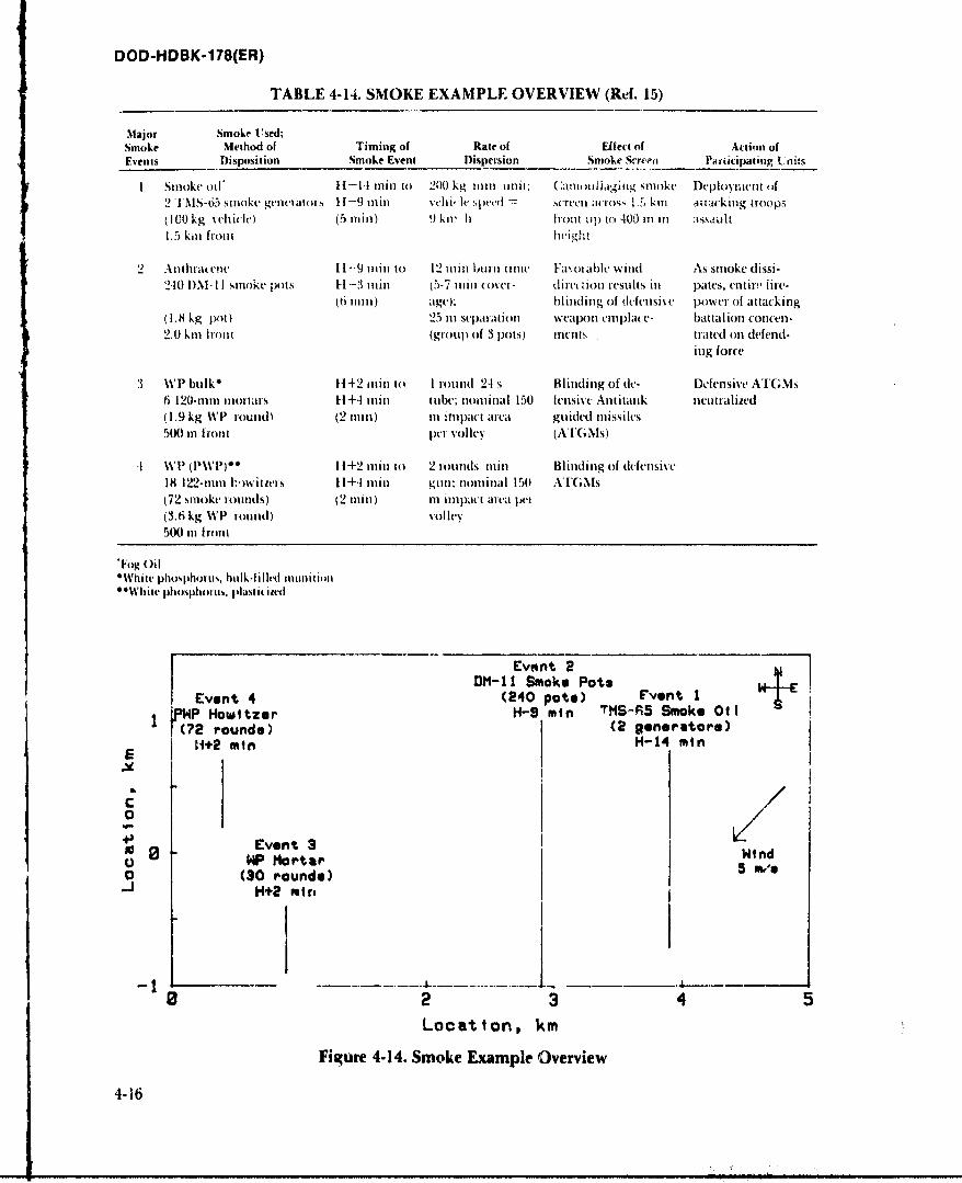
DOD-HDBK-178(ER)
TABLE 4-14. SMOKE EXAMPLE OVERVIEW (Ref. 15)
Major Smoke Used;Smoke Method of Timing of Rate of Effe of Action ofEvents Disposition Smoke Event Dispersion Smoke Srr Paliicipating Units
I Smoke oil* 1I1. irin to 20( kg inin unit: Camlliaging snioke Deployment (if2T oS-65 smoke generators 11-9 mill vcliih' eed screen mcro,;, 1.5 km i jiacking troops110 kg vehicle) (5 nin) 9 kir h front up to -t00 11 ill assault
1.5 kil front Ieight
2 Atbhra ene 11-9 imn to 12 min burn timue Fa otablk wind As smoke dissi-
210 I)M- II smoke pots H1-3 lain i5-7 min cover- diret tion resuls in pates, entir, ire-(6 1ni11) age); blinding of defensive ponWer of attacking
(1.8 kg pot) 25 i1 separation weapoln etmplace- battalion concen-
2.0 km htont (group of 3 pots) lit'llis trated on defend-
ing force
3 %P bulk 142 olin to I rotund 2-1 s Blinding of de- Defensive ATGMs
6 120-m1m motars 11+4 rain tube; nominal 150 fensivc Antitank neutialized(1.9 kg W13 round) (2 nin) m itnpact area guided missiles
500 in front p't volley (AI(;Ms)
V % P PP) * 11+2 rini to 2 rounds min Blinding of defensive
18 122-1m11 i',witiers 11+4 Ilin gul; noninal 150 ATGNIs(72 smoke rounds) (2 mini) ni impact area pei
(3.6 kg WP round) volley
500 Ot Iront
*Fog Oil"White pl1osplhotu,,, bulk-filled muniti n"*White phoslphonm%, plastit itel
Ev ,nt 2DM-11I Smoke Pots
Event 4 (240 pate) Fvent IJPWP Howitzer H-9 min vSf5SoeOil
(02 round&) (2 geferat ore)
E 11+2 min H-14 min
C
0Event 3 Win0 HP Mortar d0 (30 rounds) 5 m,'e
H+2 mire
0 2 3 45Location, km
Figure 4-14. Smoke Example Overview
4-16
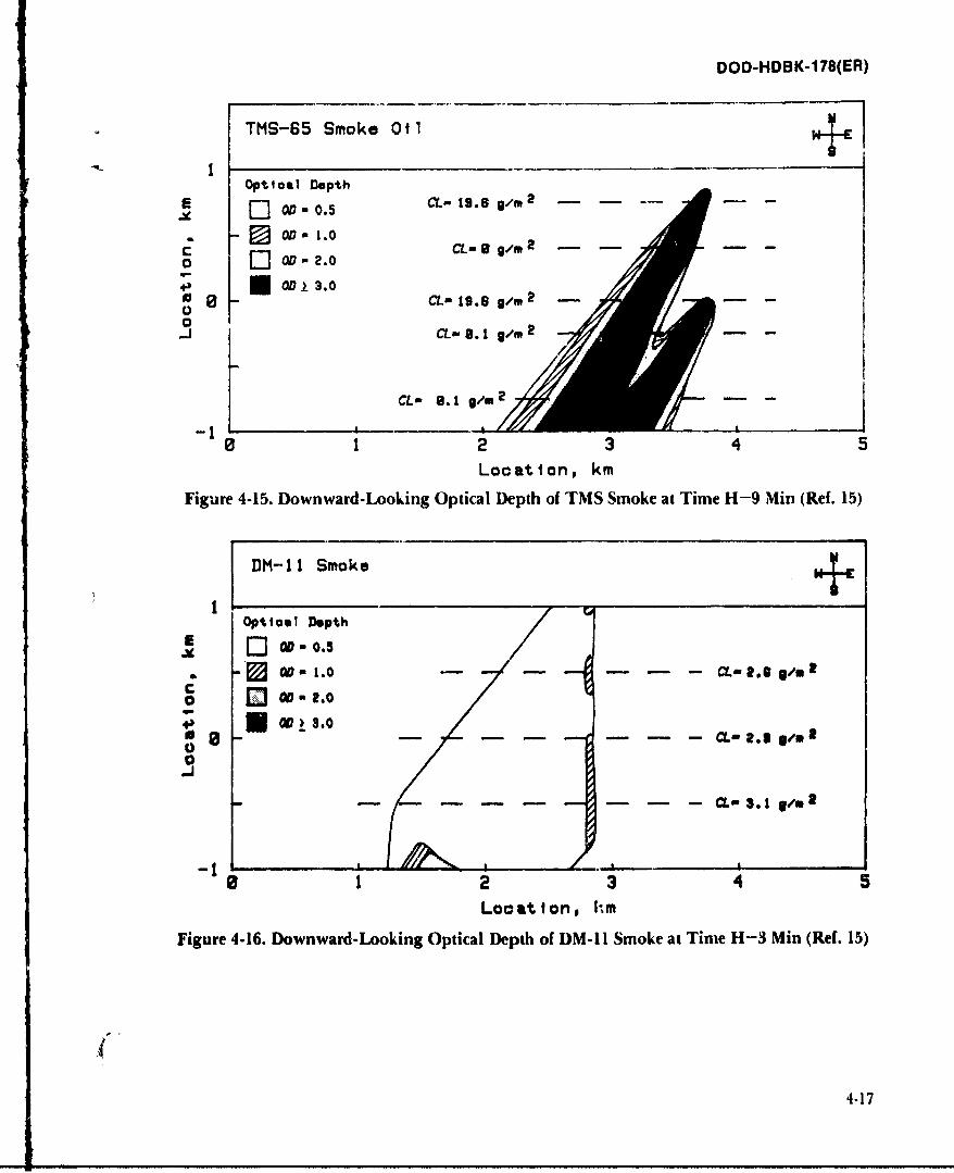
DOD-HDBK-178(ER)
TMS-65 Smoke 0l
Optical Depth
00-0.5 CL-1I.6 0/m 2
OD - 1.0
o,...J C L -/ m 2
+) 0013.0
0
CL l. 1 0/m-
2 3 4 5
Location, km
Figure 4-15. Downward-Looking Optical Depth of TMS Smoke at Time H-9 Min (Ref. 15)
DM-11 Smoke
OpticaI Depth
O - 1.0 CL- 2. S V.C
o Q 00.2.0
_j
CL- 3. 1 g/sm
23 4 5
Location, hm
Figure 4-16. Downward-Looking Optical Depth of DM-I Smoke at Time H-3 Min (Ref. 15)
4-17
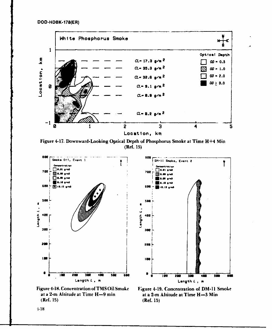
DOD-HDBK-178(ER)
White Phosphorus Smoke
IOpttoa! Depth
. . . . CL-l,.3g/m2 J] o- .2
. . . . CL- 35.3 0/0 2 OD- 1.0
C - - L-32.6 g/m2 Q 0D-2.0
S- - -S.lg. 2 i 0oD 3.0oo.J C- 0. 9 g/M 2
CL,- B. Rt9m 2
0 2 3 4 5
Location, km
Figure 4-17. Downward-Looking Optical Depth of Phosphorus Smoke at Time H+4 Min(Ref. 15)
k 1, Event -I mk, Event 2
1' C-.,..,r.,.nQu p. g.- .,C l gu [] ""78 r08 .81 l,
66 "e * ga. g oes, -see 1-n, see Ni '
- I.. g!_ .J500 5H
-Jjx" 488t C- 40
300 - 3098-* I
06
IS
I N4N56 666 a too 2 3N 41 59 on
Length L, m Length L , m
Figure 4-18. Contentration of TMS Oil Smoke Figure 4-19. Concentration of DM-11 Smokeat a 2-m Altitude at Time H-9 min at a 2-m Altitude at Time H-3 Min(Ref. 15) (Ref. 15)
118
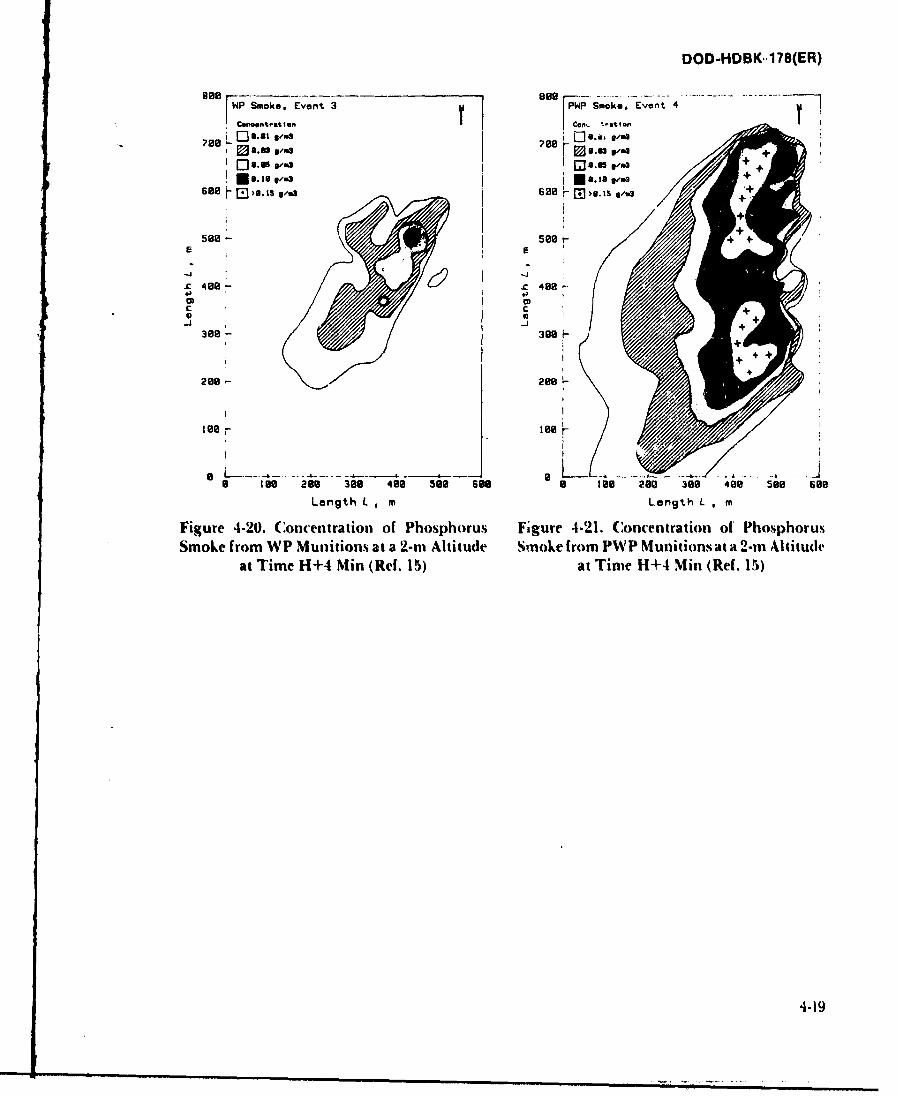
DOD-HDBK.178(ER)
HP Smoke, Event 3 PWP Smoke, Event 4
oftOeOtn st Ion Con t *-% EvI enO t
700 - ,..50700 09.0s03
J+630 r- E31i 0/w +
E 0 2500 -+E
400 00
03 I
C 0-J - +
30 30 4+
+ 4++
200 200
200IS
a -----------
lee0 200 308 400 300 see a too 200 300 400 So0 60o
Length L, I m Length L m
Figure 4-20. Concentration of Phosphorus Figure 4-21. Concentration of Phosphorus
Smoke from WP Munitions at a '2-rn Altitude Smoke from PWP Munitions at a 2-in Altitudeat Time H+4 Min (Ref. 15) at Time H+4 Min~ (Ref. 15)
4-19
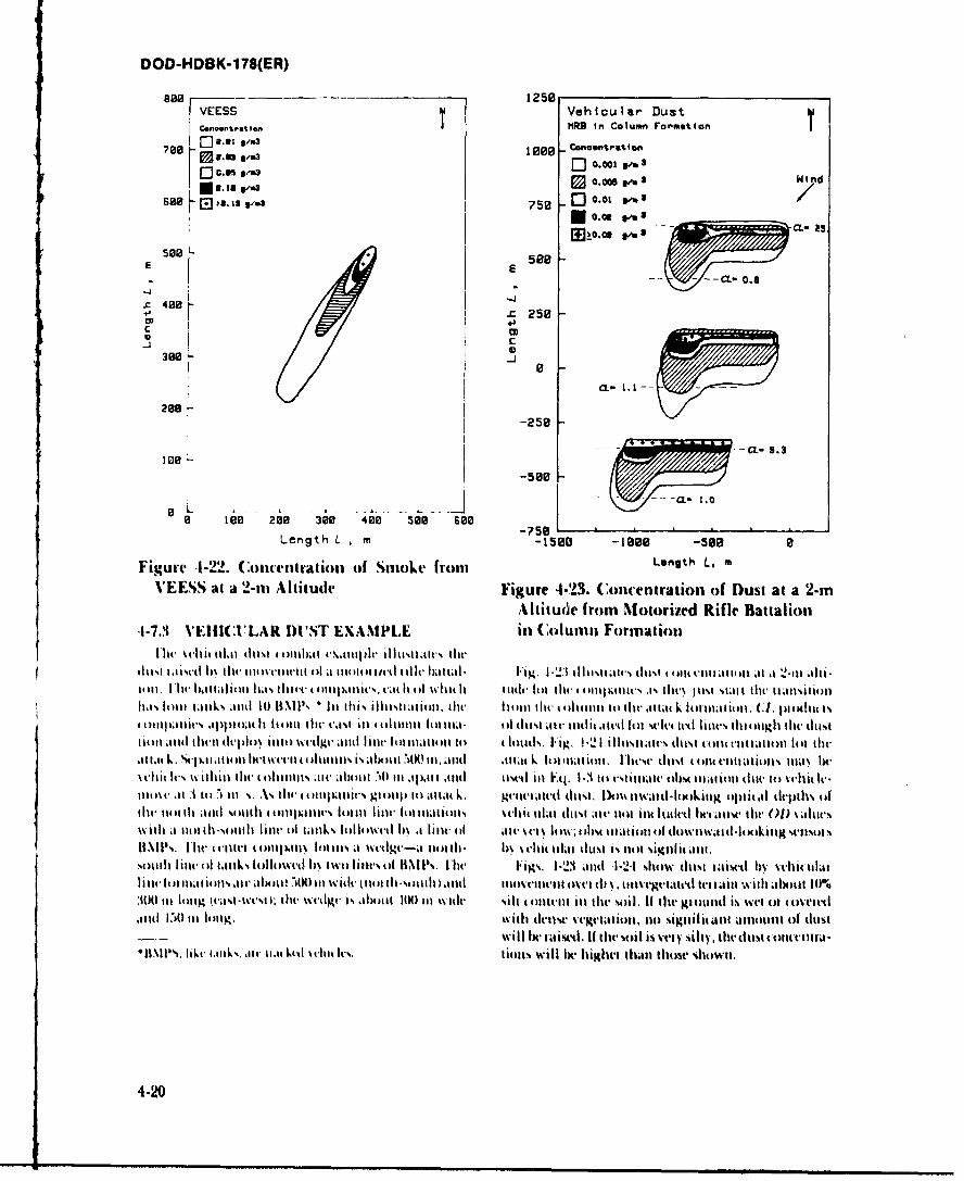
DOD-HDBK-1 78(ER)
800 r-- 1258VEESS ~IVehiculIar Dust
I j I PRB In Columni Fromtion
$Ad 0 .o05 g.. Wind
se aim ias v370 00 f
588 L *E588
C-L 0.1
38_' - C. O
2 00 -J
z -250
a--O~t -. 3
100 -C- .
-5800
a 10 00 300 400 see 600)Length L ,n -1500 -1888 -588 a
Figurv 41-22. Concentration of Smoke from Length L, m
V'EESS at a 2-mu Altitude Figure 4.'23. Concentration of Dust at a 2-rnAltitude from Miotorized Rifle Battalion
-1-7.3 VEHICU:1LAR DU1ST EXAMPLE in Column Formation
th ll11t-i4 thc~ liltg Ilelii4 44)11 1 ,1 111(m)44~ it) v ll l I i ,ihttl- Fi.4t,-ii. 1- 3 I %ilitm is dt tb 4 .itII OM1114al~l it ttI t A i-l I'll ~ b. itt 1 (3 Ill %.I.% 1114t 4 4)ll)11p ici4% c44II ll 4) i . 1 44i41d14 lilt ilt .1111)1'.t li%. I vl.i4)4) %tilt 4)14I t)l 4 44ll-ti
ilit ~ ~ ~ ~ I 141II.44 th IIIi k 4 ) ti~lt' 1 4)11ht 14)1l 111114lm% ()I~i ( 1111"t ill(- i hiit lt 1114~ 14t1 1)4 lll"t 1114' oh ti ldust
.Otl i Iv ii li Ow111 t)ltlwt'd l), awa Im l)011).14% .1 lid t)wi* ill' q. 1- 3 1114 (1i24 l oIl4 lil) dItIv 141 vhit. Iva
Ow It lil-t 1,411k . 1 111 iLoli- t il 1 11t Itliaiil hi Ili i jit l Iilia iailltitie w jut t14) il t,0).at
%%-litalo ilS20ll( l ilk o liw d I tlo l ii'%'\I1 .0)A l iilO I W IVIt-(~ i~ 1S
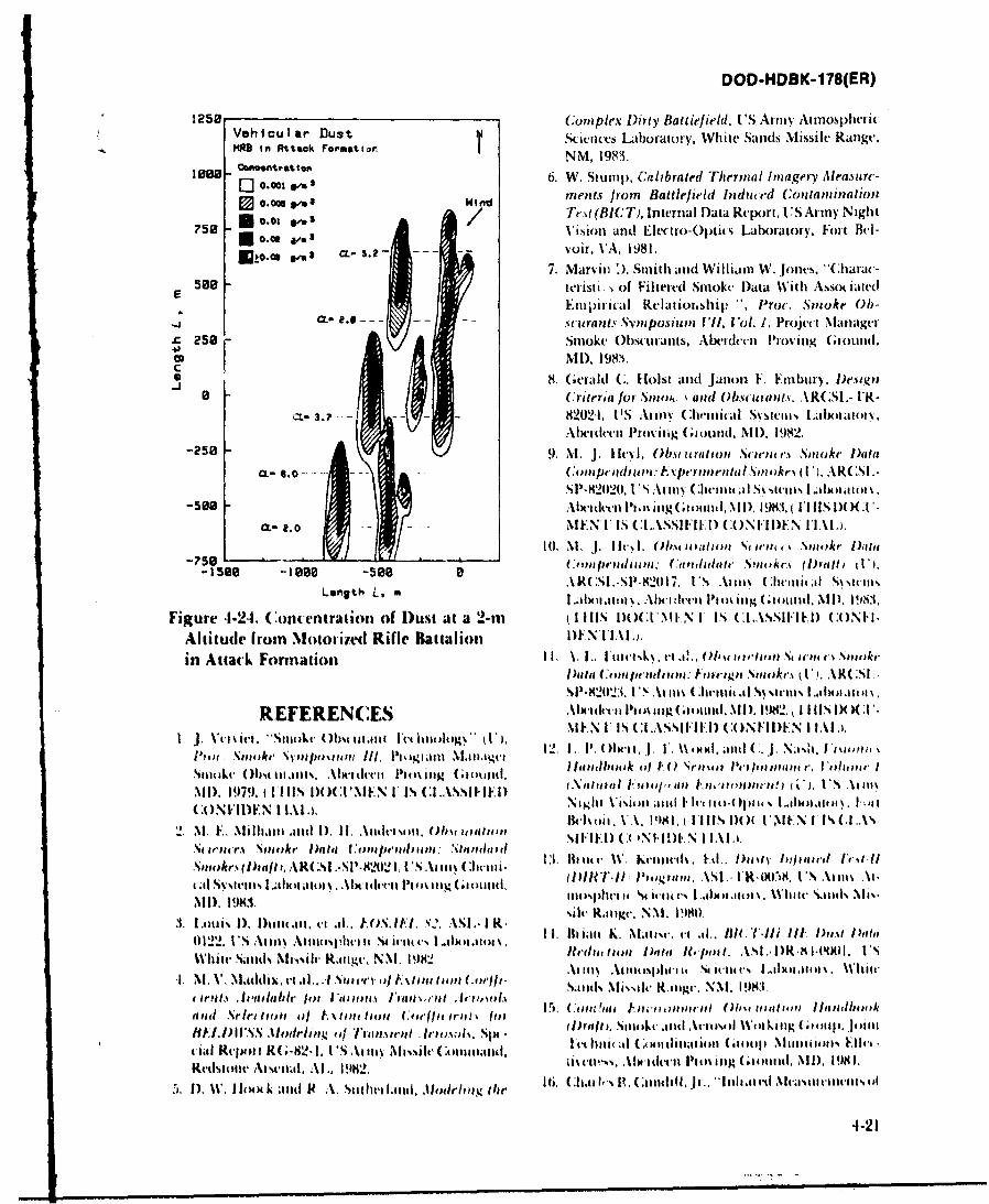
DOD-HDBK-178(ER)
1250 (:iuIarDs omplex Dirty BattlefJield, U S Army Atmospher ic
Ve Ic ormut i rScivoces Laboratory, WVhite Sands Missile Range,NM, 1993.
lose-0 0.0 " 3 6. W. Stump, Cali'brated Thermal Imagery Measure-
0 0.=1^3 Wrrflent.s from Battlefield Indii*'d Contanuznaltion
*5 - 0.01 af Te %t (BIC T), Internal I)ata Report, I lS Army N igh t?.5 8v Vision and Electro-Optics L-abratory, Foit Bt'l-
S a- 5.2 -- oir, V'A, 0981.7. Marvin '). Smith aind William W. Jones. "Charac-
see8 tt'risti., of Filtered Smoke Datta With Asso iatedla Empirical Relatioi.ship ", Proc . Smoke Ob-
cf. 2.6 - - - - -. uraat, *vposiuln I'll, Vol. 1. Project Mianager
4, 25 Smoke Obscurants, Abeidecii Proving Gtoound.
8. Gerald C. Hoist and jan01) F. Eitibui) , D~esign8 11 C;riteria for .%nao. and 0bst-urantH. AR( SL-I*R-
a-..- -L- 82024, U'S Armyi ( 3itial Svstemsi I dIi~nttvAlicideen Proiug ;i omiid. N11). 1982.
-2508 9. M. J. Iliy. 0bvu uratin Stieunis * Smoke l)aita
CL- 6. 0 - ;fnflln. ~einnf ,we .A(5
-598 Alxcitlt'cil ho% itg.ioailNII, l983,( ll~)Xt.0 No E N VIS CI.ASSIFIKI) (ONHIDEN lIALi.
10. NI. J. Ii. ().wgi, tiiin Sc IoIE r kc Ist
150 -180 -50 aARC S1.-Sl'.821I7, 1US A*imn% (llit ~al S\Sttaul%Length~ L. m I IRI awt1I% _.1.ci III(% la uaig (.11 mud. NI I). 19M,.
Figure 4-2-4. Concentrahion of Dust at a 2-in (tillS l)OC.lMIAN IS CL1ASSIFIED) (0Nll.
Altitude frorn Motortied Rifle Battalion DENIALPl
in Attack Formiauion 1I. V I.. I'l tattI 4 vl~ 0., t, it Id~iu % 11 .~ i-Otv'.tt~PDae (:tiitulds 140i: f tigna, S~noke. k U. .R( .51
REFERENC:ES IbiittPo o(.otd i) 92 II llNI)()(:1.MEN U IS Cl...XSSIFIEI) (:0,NlI)FN 1 IAI.)
ite Stmike Sv'n/n''a upi Ill, Pit Mliaiti NI.4tiiaget I2 jiii1t% D ~C ~n~D PP1) UItr ,ia't
Simike 0()tIllatIts, .Alwith-vil f141%~ili (witiild , ~ un Pe-plowiltot rg'wg~a,, .1 ~iiNIID. 1979, t Il )O(:INIMFN I IS :L.ASlII (Ni sti4)t Fil~ FI-mi'mt14A) 1 4tW, VS L~o A wl%. t
(.ONFII)EN I lALi. Nidgun VA.it a11 tid l l)(Oti %(1NNI SC2.~Hewi VI, 1981 Mi VIIItt IHndIF 1) 1. Anlt 14 )b 4
2 Na E.~ SMi oke ani 1). ee~e ILe Aitetia Si FI F. 1) (~ ) NI k N I IA I~aStfrolleL% ~ ~ ~ ~ ~ ~ I 13.IC~ bett Copl111 lo N111Wpl 114. W Killt-1rt Ell. Plittv Iu1jeea,,el Ivil-II
.Smkri~Dufii ARS! .SI.W2)2 . IS A iiI VIRTU*1 III~guifa. ASI .- UR-M.7t8, I'S A\t AI.
NSl) I9WI. hit N11(.\ i3. 1 baiii 1), Duiiaii. vi~ .. jqj0S ,. 82 ASI. I R-e NXI. l)
0)122. I'S Atim\ Aimosphvii4t St ici~- .I4.ilsmo, I1 I.ltianl l.. Mtitlis. cl .1I., Il l-. fill li t Pat l aw
White Sanlds M'ivsilt, Ratigc, NM, 1982. Ulita~ 1)1 )vglit 1?(In I . ASI .1)R I U4iIl. I'S
I. I.V.Nladi~.ci .I. 1 Sit4'V il S1,,C1) II (tWJISands MI%I i' Riiigc. NMI, 183,v irpilt Avt'ailgable jIm I 'ltlt% a Japn e ~vAevi 15and u .Se'leilltops I)/ f. 11t holl Cain (' lt it-wl (1?1.Sil44.~tlAeo'4 i il lgC ~l .l 41
Ij~~lI.Ig I1.5*ldlT t 'iwotirnt.Iii; Six - ~ Iv 116A CAN. it itliatol 0ollp (a4 M4N i411411l Hictt ial Repori R( .82.1 tI'S Anim NIiiis1 it' Commmni,,~d, Abo mess.l .I It'il'l 4 itig ( lnotiti. ).DI 181.Redstotie Au seual. A.\l. 1982.
5. 1). W. I 104)( k and p4 A. Stit hetlal,1 MIlcnjeqg tile 6 I~i~ ~ tnuI.Jrhl cm lasa lllls
4-21
DOD-HDBK-1 78(ER)
it 105niniGunblasC', (11-11 PAPER IS UN(:LAS- BIBLIOGRAPHYSIFIED), 1'roc. IRIS Symnpostumn on IR C:ountei- G. W. Aitken, Ed ., SNO W4-ONE-A Data Report, C RREL-P111,1181res. Environmn tal Research Institute of 1'R82-8, UTS Army Cold Regions Research andMichigan, Ann Arixor, MI. 1986, (T'HIS DOCIT- niern atrtrHnvr H 92
MENTS CASSFIE CONIDETIA.) . J. "-eyl, Obscuration Sciences Smoke Data Comn-17. C:harle-s R. Cuindiff, Jr. "'Launch Cloud1( Interfer- pendiun: Experimental Smokes (U), ARCSL-SP-
evice With Elci iro-Optical Systems" (IT), r( 82020, US Army Chemical Systems Lahboratory,IRIS Svin posito onl OtiR C;ountermea~isuJres, Env ir- Aberdeen Pfoving Ground, MD. 1983, (THIS DOCU-onnivit tal Research lInsuitt of Michigan, Ann MEN]'IS CLASSIFIED CONFIDENTIAL),Arbior. &11, 1983, (THIIS DOCUMENT IS CI.ASSI- M. J. Heyl, Obscuration Sciences Smoke (Onta Comn-FIEE! SECRETI-NOFORN.) peniuna: Candidate Smokes (Draft,1 U), ARCSL-
I h. John F. Ebersole, Estlimtes oif IlelitcoperIheown- SP-82017, US Army Chemical Systems La boratory,washb- Produced Obsie uration Factors. Creative O p- Abetrdeen Proving Ground, MD, 1983, (IIHIS DOCUJtits, Ili(.. Bedfoid, MA. 1984. MEN]'IS CLASSIFIED CONFIDENTIAL).
19. Donald W. I hXX., 1DOT Test.k-lalv~i.%--1)rreed Gerald C. Hoist and Janon F. Einbury. Design C:riteriaI9uot Prodiot Rawe, for Trei ked I 'ehfi Irs, US for Smeokes and Obscuirants, AR(:LITR-82024, ITSAimyn Atnuesplivt a t-tittnce I ahoiiati n. W hile ~ nvCeia ysei ~btaeiu.Aede r~
20. G. W. At :ket,. Fti., SAWII-OXf -A D~ata heporl. 1)otald WV. 11xMk. DOT Test. tineelysts -Ieri'ed D~ust(R.RKFI. I'R-$2-. 'S Atm 04~(Ad Regiis R-wait h Ilyid teone Rate.% for Trat ked I 'riie.% ITs S At my~.et F Iliti eingt I ..IM lx IIIi, 1 ait i. Nil,. 19N2. tntbJlilS e e[.I atrW ieSnd i-
21. R. K. Redilivid. W. M. Famt a, and J. F. Hwlw te, Nil k,12,4r SM. 1983.S.V() II'-Tile) S111ke 1SWek I ki F d 1),rennt P W. Illoi k and W. A. Suthriald M~odeling therI'lan. I' '%emn 01t1d Ret-ots Ri-wat handl FtMi- (:oeplev lVertv Battlefeld. US Ak il\ Atni(5pher itiivila I .al it attn '\, I I uit , Nil, 1 983, Stvli, 1411loa l . , .Whitt "iald i ak Rallgv,
*2 ? j .1. K ii St, 0#11el i f et I t riutipir? slim" NMI 19141.1;\, ifPt~entee Sub. 'I'r'q tit te, \\() W. TWOl Fild \lilt % ft 1). Ka% %. rt at,. Qititive Dr Ik tio t it~Io Ob.
1% \pre? nnt ctI Dra ft u. C:a ti ( C)lilt( ,. lilt.. Iii thil d, \(taii Fn u. Ii Cepetrl Eurape. ASI. Metmo.tMIA. 19N . giaid No, 1. 1 S Ai tit Atituio%jit lit St witv c1 ,atmit
23i. AM( :t 7W8- I17. Viigtv~~ iui Dt--oguii lalatiimioak, WhIte std Na- Ratig. N. O980I1emsiitippictitr, .%rlirA., Peart Ihire. Iidit rd Fici litt, I. W. kttnmetld, Ft.. Du sl Inijteed hst I I)t'-o t ili aiti i t I'ev. 197tiII,1qtOl.A I.U -05 .t' tn A iil-lvl
Ralbw W lxillaild1.1til'il S. .4 llite. St Ivint v% I .0ti lattiv. White S110% NMi%%it "ittgr.%jilui it Nbv, I..1ildai t l i 1 11tli tt1*, ()11114 atN i.19
Futatta 2. 18 I K~Rai 1K. khwllanna Ian lieu 111 .1. LAllinitiai, 0/net ael Ilrop-2 Kai k. khamamla .tuit I Iii ii1.111 L. AtuiIII it , (iplfe fitrlr / le i le d I ,Ltrjt e'F r 1r ds .
Coleg 1,011, N I flI 198:1. ~ f(s1. il 1w .rj~ i ,ilfJ"tr I~kjj4"
26 ut % l l, lit Ci i vi ' t N.N t Iu., I( Mal 1.1d ll. V . MldIX 19.c l. 1Ntcr ree. ue e liL rj01114-gts Pak lire 19141 \I. V.c .1 rereoeo tiec~ t f . lnecsrehb Ct ll-rtO.1h. W .n li kit At'ailoi IM'ttigttttait.li eIelati . lcrltnCu/tget r;It1/tlait Giv Aet Sniot.~pj Slw4 flpi ti. 23.ppi I. %ilr Irimne isf Pvot I'eentrc( . leittSia (tit Rt'j.0itt R
(WIN I . 9'2-1. I 'SAt it-\ Mi%%ilt' (otitmnd. R.'dsom At wimla.27. I. Haimt m ,idl 1). t ..nviut. *I llt Filt i. ill Al. WW2.
Nlolalt atatl ,~ttStnsitei j ti adit.". .P Caae. a~i ia K, Matuwv. tl Al.. / I if. Duws Ihalee ledu -cFOS l.I io;ksoc, SAt ilS Attilt%jitlt'i t ittm, Dacta IReport, ~I. )R8- I'S Autiis At-
St it e"I.abiIao lat Mstv lsilt' Kallgv. 111O..jdt ni St it-li cvI Akoart ~. , %%'Itt wIItds.\ 1%% t-N.M. 1983, aag' N\. 1983
NI. F.. Miliana and 1I. Atititiren. (Thu tjeataet St lete-e,% Smoee D~ata 0hotieritadeurc: Slacedard StswAuke
(Draft,. ARC(.S P-8220 1. I'S At tiv (.ht-inua AtS%
tils h\latt~.Awdet ~o u eoad I)
DOD-HDBK-178(ER)
D. Bruce Turner, "A Diffusion Model for all Urban Other Data SourcesArea", Jou4rnal of Appled lleteorology, 8 3-41i !eb- i addition to tht, documents 11t'll ioned, lic proceed-
ruary 1964). igs of relevant s,! mposia are extilent data SOUlrCs.
A. L. ruretsky, et al., Obscuration Scieme Smnoke Data "h,'se include
Compendium: Foreign Smokes (11), AKflSL-SP- 1. I. OSAEI. Work, op, splsored i y the US Army
82023, LIS Army Chemical Systems Laboratory, .' nosphcri( Sciences Laboratory, White Sands ,u s-
Aberdeen Proving Ground. MD. 198,1, (THIS DOCU- sile Ran~y-, NM.MENT IS CLASSIFIED CONFIDI:NTIAL). 2. IRIS Sympiosium on Infrared Countermeasures and
Combat Environment Obscuration Handbook (Drit "U..IS Symposium 'A Infrared imagitig Systems,Smoke and Aerosol Working Grot,p, Joint Techi, - 1ducted for the itteol Naval Research by Envir-cal Coordination Group Munitkins Eflectivc:,ess, onniental Research Institute of Michigan, AnnAberdeen Proving Ground. MD, 1484. Arbor. MI.
Smoke, An Obscuration Primer, 61 JTCG/ME-77-13, 3. Smoke Obs urants Symposium. sponlored tileJoint Technical Coordination Group Munitions Prog, ni Manager. Smoke Obscurants, Abci-enEffeciveness, Abe-rdeen Proving Ground, MD. 1978. Proving Grounid, MD.
AMCP 706-117. Engineering Design Handb ok, En- Snow Symposium, sponsored by the Cold Regionsvironme(tal Series, Part Thre-., Indured I-mviron- Research and Elngineering Laixratory. Hanover.mental Factors, 1976. NH.
TRADOC Pamphlet 525-3, EnaPlov ,m',it of Smoke.1980.
4.23
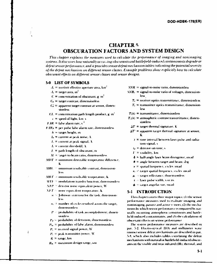
DOD-HDBK-178(ER)
CHAPTER5.OBSCURATION FACTORS AND SYSTEM DESIGN
This cha pter explains the mneasures usd to calculate the performnce of Imaging and nominagingsystems. It disc!Lsses ho, pnat urally ot cu) I ng obscu rantIs und ba ttefirld-induced -oiltam Inantis degrade ordlefeat senisor performpanc(e, and( It provides senisor defeat mechansm tables indicaItig the poten;tinal severityof thme defeat ,neclmanuin on differrnt sensor classes. Example problems show, explicitly imow to calculateobscurant effects onl different sensor classes and sensor designis.
5-0 LISTOF SYMBOLSA, sv'Viver effective ajwr-ure area,. kil N = sigsiatu)itoisc ratio. ttlttmionklss
1, taget arva, lut SsVX = siguad-to-nise ratio of voltges,. dirntnsion-C osuvroratit of obst-uratit g li"'les
C= targt cotrat, dimitst les T, = receimv optic% transmittance. dimnsionttcss
C. appaillttarget contrat atI s.etr. (tjlttil. = ransmittevr oplics trtn1itaastt. climension-%ionlm Itm
CI1. = tollieittl~i Patih knIt-it prnMiI. g 1112 TA) = transmtlnt vt dimniioik1t= 'tlVI 01 light, kill % T,(A) = atsic~tic (trsttI traIfliittam t, dimn-
1 FR = filal"11 raairwt. ." iolllm
I lRp, = IW1 PtI~ aIW IA i iii IJV A T = trgt thevmiaI !iKnuh te. K
It " (I~lit lt1viMtt. IIA*=aprnt tatros.gvt thermal %1gigturv At wm
= i itII .11 .k %tigllI. A = tollit aitim. bctwvA~tl tsla t pum-i tt .s tiadla.
tilill II V= dcvil.u illB~t
til '. 111oit. t .ivit n i ii t t1ilth l vii"v 6 = ldl-i gin~ r law s ia thm iit r. ituml
AM C i 1114i111 1tiit Irmi *maal h91 ti qii.w . d1114,11 .n. v %jullia l i tim % lIt~ p Ir. (5 itt wt
596.I lil.1illaiot tint%,.i~ i tI t tiles ('a %IM 1t1 fitii cli j l %t4IV1410 1 141
11111114I1MIt11.i Ic s5.w ain ic tii ia iiiti.t'pc I l ita~m xvi IIt .lisl v.91 't~' 5 s. ~a a
li iS$ 1,1 Stlto iilt pkia i 111 11t111. 11e Ii4utaaott' III1 tIi-ts *dw inm. I)I 111. w
1141m Irsiiigc.ilu k ~ s-i , O tUtr S.)IVt)IISnMNt t~~
It, Z I illm- of4 % Iv m shvl '41o'.lil- I pgr. itllitimihg pawilt l slita m %, b 1A i b %dt lit-l i lt-, II 4 i
thilt-m t lt Ir% lt~ll% h u~iq t M11%o IN111tlim iq 1%1111 milll 1% ia
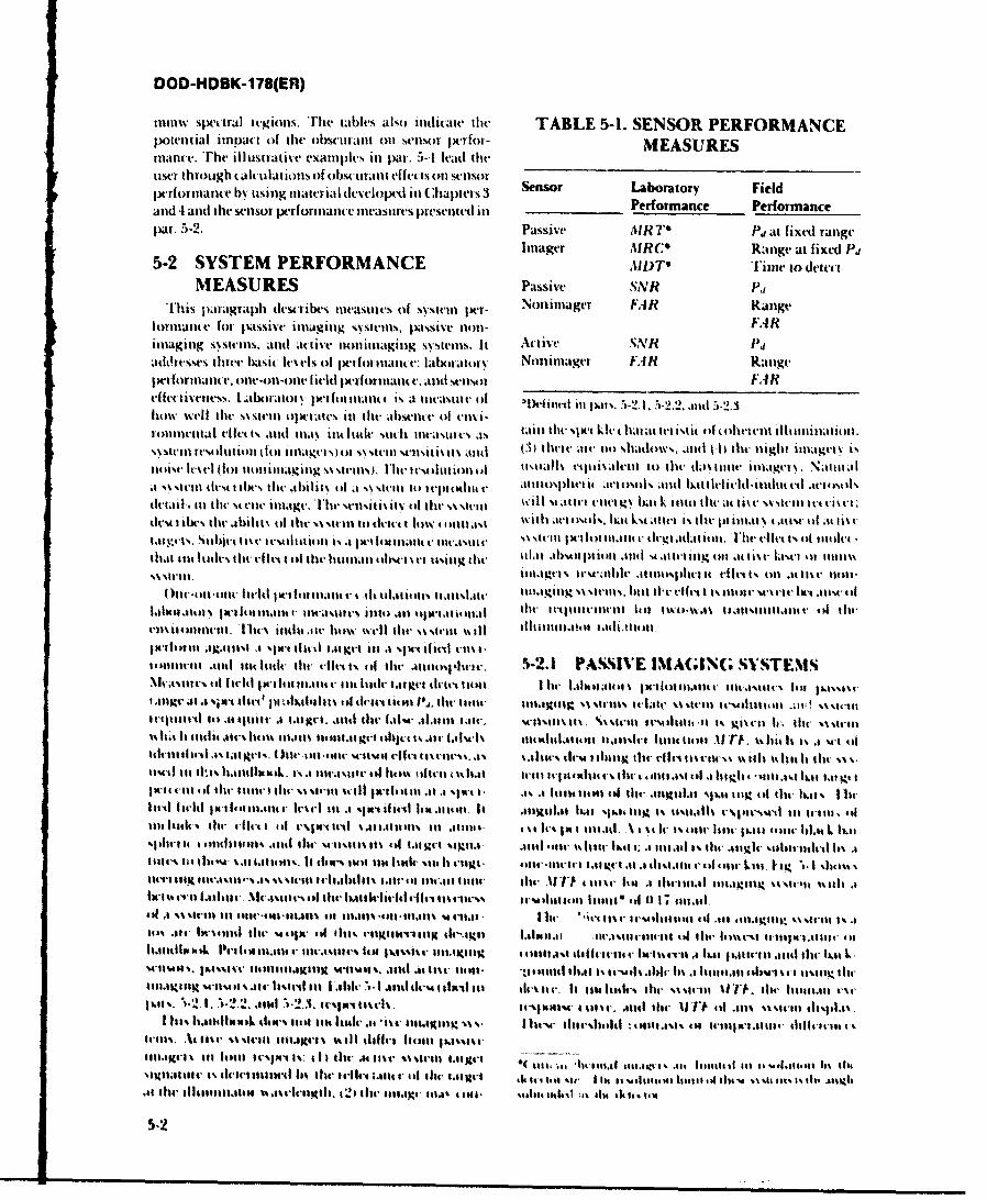
DOD-HDBK-178(ER)
imw spek-tral itegions. mhe tables also itndicate tilt, TABLE 5-1. SENSOR PERFORMANCEpotential impact of the obscurant onl sensor perfor- MEASURES
mauc'he* illustrative examples inl pan. 5-4 lead thetF ti~~ser through calculations of obscurant effects on sensor' SnsrLboaoy il
performance by uosing material des-elope-d inl Chapters 3 PerfLaorancy Fieldrmncand 4 and the sensor tx-rforniance measures presented il __________Promnclefrac
par. 5-2. Passive AIRTO Pj at fixedl ranigeImager AIRCO Range at fixed 11,j
5-2 SYSTEM PERFORMANCE 1I)T' Time to detcutMEASURES Passive SNR Vl
T[his paiagraph dlewtw bs easmies of systemtl er- Nonimager FAR Rangelot ialu~e fo t pssive imaging systeills, liassive n10n- FARima~ging systetnis, wild act ive nonlianaginig ss-stemls. It Active SNR 1
aidtt'sses itt( baSic lVels of Ixlrfllancte: labaratory Nohlimlager FAR Rangetwo fortnancie. oneo-onl-onet held IX-rformitn V. anid sensor FARehit-%Ss, Labtt or\ twr1lonancit Is at tineasumt of "lD1itieil pats.5:-2. 1. 5-2.2. and5-2-3hows wtell tile t- t olmk-ries mn the ahlete of ensa-
enlmrlta I ellet I% atid a. lilt Itaiec It 11cmlt. taii tilt %lx-t kit- llaat ivi itt foern littia ot
ssiei eol iol oimagtstu tinestist. il 111401 t tltat alt t o iat), n tilt heitmt itigvt\ iingt i
a te t'stll tI lilt,. thle a1ilit\ (if t a Ir it) s it rp!Emintt attlopittisitt aelsol\ andbi d ed idte etotd
dtail . in the ut-lne iiagte. 1enit isi tito thr ,\%steilk will st te l gs hatko ntwo lite at lt t .sen e tdes4 t ibes the ahilI it~o es t odt lmw mtltlas with arit1\4 1st s.ba k54Aittek Vs tilt I itlat t atast'ol at list
ta es toj'tis e* stt it-At is a llowat naskilt . s e lot mane tiegi aat itonl, Vlw elles 1 t t aneiluttOat im thides dtheitl t All the itum.1t tthwt st tsing the kil.m ,ihstitioll 'Ind si atteitig at i.4M t'l- ltse 411111m,%\4t itiagv1t s teselnic mtiopht it vitkt ts oilI.41 atit non
( )ne-till-olt field pe e aheitna ts~ailt- itaii sses ttiritet Is al1tlt U unrt' tM't alw tit1.1611.11,01% Iltt lltltt tlttstites 11114 .41 dww atmna h' ttiit utltt Ito tWJst ofisnitat i thrt-1ltiltelit. l14it m. ieito well d1w sssieal% %611 ktllmttot tattimitll.
li-1w lr It.ts a sNwti tt mta t too iI , t il orl vmld ii116t1n4tilt antid tnt1m ldtthu O-lt-A1 iSol thet mitnos;'ha'te. N-2- PASSIVE IMAGING SVSTEMSMlv~m ttsio l l 't1iltt r ltl ilt litile laigrt tl-tt ilal tie 1.1ileateit IN 1 i lt 111.111t U l11latlvIt' s $tt.1114'31. Sovlihet o liaelhssf tintsm P101 Idw tilt- e ttAgltg 1 tel it-late %w5 itt'iieli lm .;wsst-
5 it it tllh its ~oiltss6 1.1t51 tltlt tttjt ihu . ti-i wtr tlatil tl~tll itl.hiltI .'% qr~rti lh tiist m.sa'illilttih tiI'ale . tlltll u t f tle t dit tt-.. all 1.11.\ Iituts thot ilt g t1.1 t1' ellis 111111 's 511 . lilt It lilt U-1 ti
ostt i tis anfhguL. ls( 114W-1111 l 404- witl~ elit ilt-% si.4% ttI tl5)lli 1141%5 lIi's*ultt cli %\ Itii %% alilat Itidw %%gut
is t t i t ti t i di i k . 1 % .h e 111s ss 't ill 5 th oW t itu t Illha t w ille I a . i t lit t it vl f il ' t 111 .4 l t l t lll t-i t il 1b.0 I Ia t 1. ltit-it emt i t ll- n 111 tq 1114 \ .I will Itfitd Il. itt.1 it4- utigit.la111t lotso off Owl .11ils .lu i 4*1 t di t- i In hulail iit h slt I r f t l i~' et . 1-1fr t ulst ill.ll It ts .11its pe t11Il . i ll m 1% W44 i 1.111%tieils l t li a ll s111lgh tt ttl ~l lt h'sastsiso ~tglsgl tt at sill-e l-14tt ilto 1116 (% Ir au 41ilt0 .it 1611 floor .tIt il ihttt lit
t~tls i) illwt- i tltliul. lsi s l- e lil im it ih mu I gi ollt l it't j tat g .11 .1 1istijill %' of 111i4t kL. ' . * 'WI sit1ss
ilalthlt bkPea111 t~lll.I' lle.stat-s 1vi ~ langt mv111e" othu i .111 4%14 tt'l . iit'et.'i a ha i iw ou ititi ll at
4115 a u t m2? I tAit 111.% ie'it t11.1till -el.ult 11,11 .4mt1 Ie' Ill'. lilt .11o1tl 5tta lllifil4lil iold~4 titit %$f ilt fhtt E.g11 'itt' In ti i I 1.41ws I It' 'tieh li Atltst t4 lil li tl - )* lt.-, its
t4e11%411 . t1s' sttei 10 1 I titl tlt si*tt .111 1 atI -lt l V4I414 1.11419M1%.1j -1%.1111111 1 I%111%1% 14itl111.1v I i ,114 o Me ' is: I t l I it I .114 t* * St .11 11- I its~ dvo r ti I t o uiti a-%ti. ~ isat Titue t Ilkuii 1m 111 v6
It tIt lllialliilil, 444. . is l ltilt 2I u e tat1 i .1 ., ti nt ui 1n1-4a144! :411111.411 1s'"I
5-2
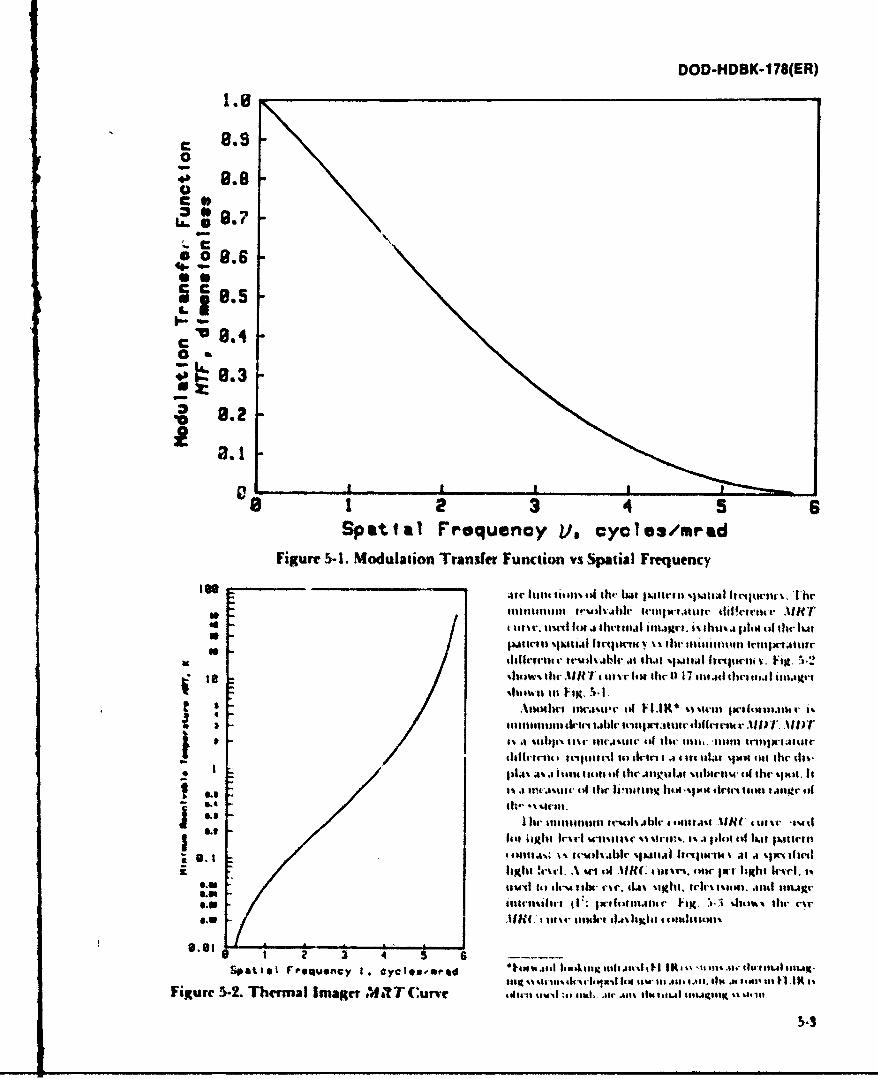
DOD-HDBK-178(ER)
0
. s 8.70
L.
8.3
~"0.1
0.
08123 4 5 6Spatial Frquenoy, L/, cyeles/mrad
Figure 5-I. Modulation Transfer Function vs Spatial Frequency
111illisitimi frud'."t1r triIt-ta sI wr J.Ivtti AR T
S~~ tlt~r, fnir 1.a ivta.ImgI thatr.i ., plibitol1 dir Ima
Ito~ ~ ~ 411it ri4)IiJNC . dhut %IM1tAI Itttilwilu. i. 1.2%Iultwi 41VIR. .TII tiw It" thr 0 17 1141A Ifil IgI& imm-
1111111 IIkrii-ttsirIt11r .14t ti lihm rinll) iT.AI
4d1tteffit. tergtia11cd its i 1 .1 4I itskial %juvi -Is thr kit"
111,1% a%.1 Itiou 1#0114 111 .uto~lif iitrolm Isi tr -just. It'i. t,4jiIIII is thc .1iuii1ng 1bo*.iao tb-in toom 1s4et1tr titIS..it- % irma.
e~g Ist igbt It-it- im-lic -.' itret . I% i l ) IIIau aIf 1161 trill*U]I IiliIIai... lk. Irili %1"1.11 11riwot)4 % atJI .IX$114
8. Uw ai'ts J" u- tob- rat-. 414% till. ogrt mtal) msid tiug-
S*tt a I fVeq~~Cy I C* Jy OgSOeePd huu .*1AII 141481lj: r a I '1111 aI.t*- slINm11 Mug'oilo t aikik I a-u.m Itsoaw- If, I *l mi.daw "I siw Il W I t ItFigure 5-2. Thermital Imager AWN T Curve g411IIW -. 0. and. .alr.om 111mittul lisArp~sig wk,1' Ito
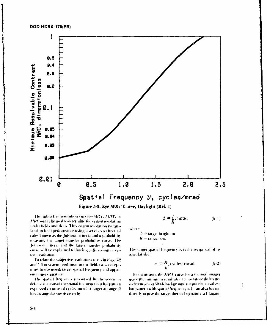
DOD-HDBK-178(ER)
40 8.48.4
0
00
mz 1.0
8.84
8 5 . 1.5 2.8 2.5
Spatial Frequency V3, cycles/mr.adFigure 5-3. Eye MRL.Curve, Daylight (Ref. 1)
ittdt uised 4 t~d o tt ilt Ow % %IyItI I t Iiii lt ol R411 1.1
t~ ~ ~~ tltv u Ie kit-ld olil Ih J4l%' I'll i a It-mi .. 14.4ol IMIls41ltIP-I4 I
Lowd IIt tiad JR.ge al .il ea to aso lIa usjw yetli 'I tal g(. lit a t, lital(ltI%4ov Ow 1tale 1. lia 11141 ploixi( it i~l vc Fr~iah ll,' tilum t iI toie il eJ l i ~t, tIIig ta d ki~ primb 4iIletad )dlfIeilCIy, ' %a~ttl1444a I
di11141 a 4,11 %vv It %lition illit fi 1d eletetitpts 1Y. I tYc Itl) 1111-a il (5-2
evpIm%%vtI Ill mills1 of9 I . lvN tolt at. A\ I.I 4t1 I ill 1194et It h i m lttt H with Ioi a fi t -iteij L I v a. It 4l di% k e 1w editdhd% , ut; l slj~ ivd 11 4i k ll b% ditI toS M1e ti h e t Ii .4e4 l~ 1141 igliltllt AT/ (9itil.
5-4
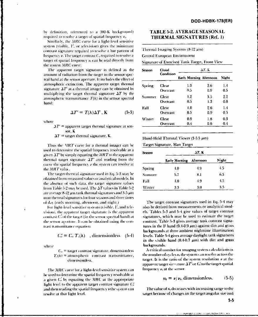
DOD-HDBK-178(ER)
bN delintilon. referenced to at 300-K background) TABLE 5-2. AVERAGE SEASONAL.ite-uired to it solve at target of Spatial frequenicy V,. THERMAL SIGNATUTRES (Ref. 1)
Siti it IN., the .IIRC curve for at light-level SensitiveSystem (visible. I-, or television) gives the ThralIagnuSsemnu-2pilcouitlast Signalture requttied to resolve at bill pattern of hra maigSsem 81 mfrequtellNt V.h rget (outlast U.,r~ur~ orslea Cntral European Environmenttarget of spatial frcqcyl i' an be read directly from SgareoEerieltkFr wthe system AIRe? curve. SgaueoExridTnkTarget, Fron View
The apparent target Signature is tdinetd ats the Season Cloud AT Kamount of radiation from thle tat get inl the sensor Spec- Condition -
tral haid at thle senlsor aperture. It includes thle effect of Early Morning Afternoon Night
atmospheric extinct ion. Thle apparent target thermal Spuin~g Clear1.26 14Signature .A7' at at thermal imager (-an be obtained b%' Ov'ercast 0.5 0.9 0.5multiplying the target thermal signatuire AT by the(
atinospi eric transmnittance T(Ak) inl the sensor spectral Summnier Clear 1.2 3.5 2.2
band: Overcast 0.5 1.3 0.8
Fall Clear 1.0 2.6 1.4AT' = T(X )AT , K (5-3) Overcast 0.5 0.9 0.5
Witer Clear 0.9 1.8 0.9
AT' =appairent target thermal Signatture at senl- Oecs . . .
sor, K___________________________________.Al tat get thermal signature, K. land-Held Thertmtl Viewer (3-5.5 prn)
Thusn thet 1IRT7 curve for at thermal imager c'an be Target Signature, Manl Targetusedl to tleterm me the spatial frequency resolvable al t a esn Tgiven Al -by slimply thelin dAIR Tto the apparenlttherm11al target Signature AT' and( reading from the( Early Morning Afternoon Nighti-tirve (te Spatial frequenlcy V thc System ('iii resolve at -
the AIRT valiw. Spring 4.0 4.9 4.5[he target thlterta~l signatire tused inl Eq. 5-3 mnay be Sumlmer 5.7 8.1 6.5
obtainled from mneasuted vallis om atnalytical miodels. Inthet absettee of Stithl data, the target signature~t valtes Fall 41.0 4.9 1.5
Iromn alc5.2 may eue.[eA a isi al - Winiter 3.3 3.0 3.5
ttla n I tenl 11a si gna tt s I fCot' tr Sss u s antid tIt te1e I nteis
ofdy(al onng, afternsott, and I ight. ) The itrget cot)trast signatures tised inl Eq. 5-4 mayFor Iiglt-levcl sestv ~ses(iilI 2,attd tcl- also be derived front measurements or analytical mnod-
Visiot , the apptcl~l~ ett taget sigttotte is the aplllt eis. Tables 5-3 and 5A4 give valuecs of target conltrast
tonit rast (',,oh Itte target (ill lte esor Spetr al halo) at1 signattures, which may be used to estimate the targetthe senlsor. adl tite. It anll he obtained tising the ((tIt- contrast. Table 5-3 gives average tank contrast signa-[last tt aisittiltam ec eqita tiolii tuires inl thle 12 band (0.4-0.9 ptin) againtst dirt anld grass
backgrounds ait threec ambllient nlighttime il lutninationt
c=', c, 7,(,\) , dinictisiotikss; (5-1) levels.T1able 5-4 gives average daylight tanlk signaturesiii the % isible band (0.4-0.7 Mmn) with (dirt antd grass
wilvic backgrounds.C" talttet olittast !SigilatiLme, ditttettsiotle~vss k clfitit *l tlttl)eT lbr titagIltg systemI alkttlatiMnS ts
I,( Ai atlitoNphitti it olilasi transmit tancev, the ntim11ber of cylsnt tile Systemt (an resolve across the
dliiteisiotless, target. ht is the ratio of the System resol itionl v at thlealpparlitt target si-' 'ittwe AT~ ir C"'to the target SlXat ial
Ibo' .111C: tit ye lot at light-level sensitive Systemtt£anl freqlitt), P, ait the( sttsot
Ix- lised to d etet milie tilt- Spat ial lteiiil Nre(solvablea at/pdimnil ls. 651giveil C", lby eqttatittg thet ,liR( at di ail1Crit tit IV,(ifh)IfkS 55
li ghit level tol the app a ret iaget oltit last s igi tat. ireatnd then readinig the Spat ial i'etmlet N t the System call [he 11Lvalue of Ilt dtIcases with incteasinig tange to theetsolve at that light level, target because of chatges ill the target angular site atid
5-5
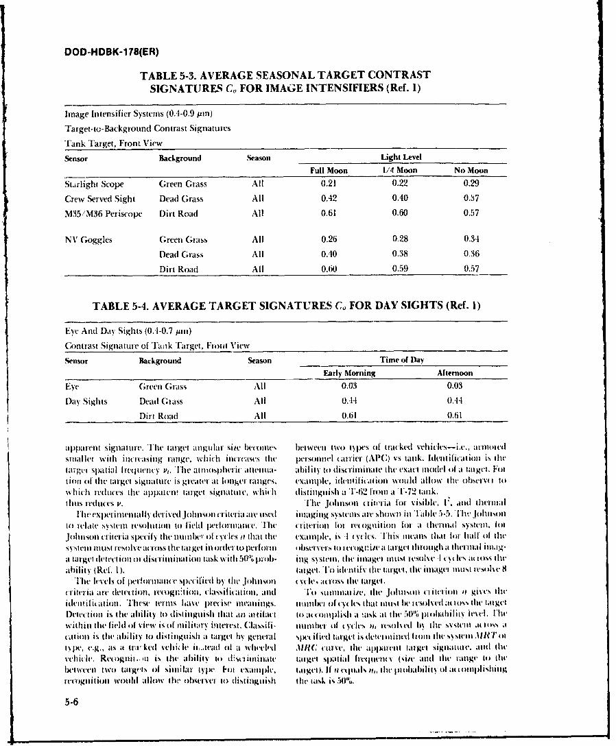
DOD-HDBK-1 78(ER)
TABLE 5-3. AVERAGE SEASONAL TARGET CONTRASTSIGNATURES CG FOR IMAGE INTENSIFIERS (Re[. 1)
Inlage Intensifier Systems (0.4-0.9 pin)
Target-to- Backgrouind Contrast Signatures
Trank Target, Front View ___________________
Sensor Background Season Light Level
Full Moon 1/4 Moon No Moon
St~irlight Scope Green Grass All 0.21 0.22 0.29
Crew Served Sight Dead Grass All 0.42 0.40 0.37
M35/M36 Periscope Dirt Road All 0.61 0.60 0.57
NI Goggles Green Grass All 0.26 0.28 0.34
Dead Grass All 0.40 0.38 0.36
Dirt Road All 0.60 0.59 0.57
TABLE 5-4. AVERAGE TARGET SIGNATURES G0 FOR DAY SIGHTS (Ref. 1)
Eye Anti Day Sights (0.1-0.7 pin)
Contrast Signature of Ta-ak'ITarget. Ft ot View
Sensor Background Season Time of Day
Early Morning Afternoon
Eye G;reen G;rass All 0.03 0.03
Day Sights Dead Glrass All 0..14 0.11
Dirt Road All 0.61 0.61 _______
apparent signattirle. TIhe target angular Size becomeits b~etweent two types of tracked vehicles-ixe. armioedSIn~ai er With incre~asing range, whiCh inc leases the p~erso)nnel carrier (APlC) vs tank. Ident ilicat ion is tilela".gei spatial frequency P1. IThe atiosphieruc alt tenta- abili ty to discriminate tlw exact mlodel of at target. Fottionl of (lte target signaltire is greater at longer ranges, example, ident if ication would alIlow the obSvcIvl towhich reduce's the apparen'! target Signatture, which1 distinguish aT1-62 front at T-72 tank,1111s redlttes P. The Johnsont criteria for, visible., 1'. and tlterinil
11wl experilienl ltlly derived ,johnSoil cr iteria are. used Imnaginug systems are shown in Fable 5-5. [hw Johnson1o te1late System resol ut ion to field pe-lrhiitatce. The criterion for re~ ognli tionl for a thermial Systemt, lotJohnlsonl criteria Specify thet nttin1ber of ('vcies it that the example, is 4 cycles. [his Itteanls that lotr half tfIlihSNysteli inltist resolve across the target inl orcder to perform In iOservvrs to recogili at tarlgtl I Ilrouigh a therl i inag-a target dtetct ion or discriinmat ion task with 50% p:-ob. i ug systeml the inuiager Inuist re-solve I %cs itattss lit-eability (Ref. 1). target.Tlo idc'til the di target, the irnager Inkst eole8
Thc levels of pt-hriace. specified by tit hnilsoi ltl: across the, target.iliteria art. detection, nc gntion. classification, atnd TO Stialntnat id, t11V JtdinISott (litt'ii I gives lit'
idetli ifitat ion. These termsl have preCise uniingS. nant111ht of(N(I. cylestat muitst be i esolvetl oss thet tlilgtIDetet tiott is thec ab~ility to distiniguish that '1i1 at tifat1 to attomoiplish aI ask at lit- 50% piobahilitv lvel. [helwithinl the field of view is of militaty intere'st. Classifi- litinlber of cyclets It, resolved by thet sy.ste-Ilt at loiss atcattioll is die ability to distin gtuisit a target by% getneralI s, et if itd tilrget is dee Illmet Iml fiOiwhes tmi I'tIl't', e.g.. ats at tra1ked %,0ii It- ii;,teath of a wheeled AJURC curve, the aplvritt tat get Sigliat iV. aMtd tilt'vehicle, Retogitt. is tht ability to &thii iniutate, target Spatial hecqInevII (Silt' and lite aige to thevbcwN-eII tWO targts lh I Sitiiar type' kit eaImIple.C titugt). If It etas I,. litim 1)1obabilith 0Ii ;1t tot iiitIgt-ecogmtit iou wouldt al low tdw cdbse-lvvi to tlist i nguish tilit, task is 50%U.
5-6
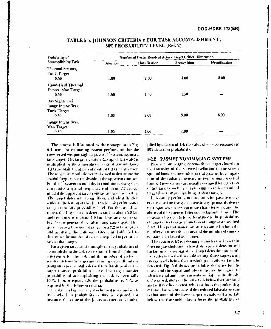
DOD-HDBK-1 78(ER)
TABLE 5i-5. JOHNSON CRITERIA n FOR TASK ACCOMPi-ISHMENT,50% PROBABILITY LEVEL (Ref. 2)
Probability of Number of Cycles Resolved Across Target Critical DimensionAccomplishing Task Defection Classification Recognition leentification
Thermal Sensors,Tank Target
0.50 1.00 2.00 4.00 8.00
H-and- IHeld ThermnalViewer, Man Target
0.50 1.50 1.50 1.50
Day Sights andlinage Intensifiers,Tank Target
0.50 1.00 2.00 3.00 6.00
linage Intensifiers,Man Target
0.50 1.00 1.00 1.00
T'he process is illustrated by the notnograin in Fig. pliedA by a factor of IA; the a tiv of ti Pi con esponds to
5-4I, used for estimating system performance for the 80% dletection probability,crew served weapon sight, a passive I systein, against atank target. The target signature (G, (upplt left scale) is 5-2.2 PASSIVE NONIMAGING SYSTEMSimultiplied by the atttll h'iti cohltrast transtltlittitt1(. 1hawa't' tlotnimaing svei de'tect argets based onT,(,\) to obtain tdw apparent cotittast C(( at thet sensor. tile ilttn.ity of the Ctelvd rthiat ionl it) hie senlso rT'he subjetive resol ItIionl turve is tused to delutn ticlhe spvt IIi l baild. of, Itt oi In til pt triAl -,% struns Inha npa
Sp~at iaI frequenlcy l, test daable at the apparent colit a.si. ) n of thle taiiant ititclnsitsy inl two0I 1101 Sx-( i ae5~~lFil It ii. V Ssstin inl mnoonl ight Itldit ions, thet s\ sttt I ,idttl. Itit'se %sts usate uskillv% detsignled (il ildetee ionfal iutsolat af spatial lieqemticne j, v o allot~ 2.7 w It-% (it hot tat gets "10h as aite rait .'ngialis or1 [or let ilitialmr1ad ifi he apparentl tatl gelt cintrasi atlh' es is tl.18o tait edetet liotl td It ekiteg at %[hilt I hlllc%
The targeut detttion, Itt lgtlitieon. antI idte.t lit iiol I .. bonatolN y p''loit 'nllite me1laure, lot ps ise 111.4
m ales at te hottentil ot. heillt t y-id task petilortat 11;11 r v'Is i Ai~ Iae In mth I s IcSNtem seI II.(.itia It IN(I) itnlt Ill% dtivcalga tile' 50"o ptohabilit% luxtel. Fo ilt- th ase illi- tol lesix mtse) Ilii "N stetlt noise, I hl(ic ol t s. attel tile
li ,td. thfe V ,a sNtel ti duet t a lank at abhout "iv8 Lil en ail i% of tilt, s etl to Iiitt't olit 6itikgtotattel tanise. 11wladd itbgtli/t' it at about 1.9 kim. [hetagyV1absoi1tletsto ilis tl livid Ilillo nt1t i'ts thc jllibiliiI
Fig.t,.I ae gtwtteelha abetititg ta ge sp~t~l it'. ill tlgo ticiet tiotl w., a 111itio filt ka1llgv at a .Ix't ilwtdtltt'tle t' r a lout tioti eel tilge' llt, 1t '22 tit tailk 1tlge't i lit, I Is Iwile. tt UtV iIt~lV'at' 4i etitls t14t both thlt'jind apph1 Iig theilit s1onl ( t ite'l ii ill I able t it) teteertiwr ib toll lt I ct liots .111ll-,tenl he' wh't ol line's a
ett tiile thle litttllhet 4f11 t Itvs ;I Iteetii el In) Imtll t it t1.ltgt hs I lhseel a'% ait 1gtL
task atl that4 latlmgt'. I lht NN steinl V11? is .1 dtgtt 14.1 iamlt'e iva tv4 it) %'t 11teIF i a tl tat gtI *ttte atoltn ep diet e. lii plotil'I lit id it tolt Ill w'siioid .. t is ha%"t Ii I~lwt till tlet tot 1.1tt4
at tMililisliitiig tOe' ta1k is 41t'te'tt iiil littt ie iiiiet balt Lgteuinel it lis' stattstt %. I .iigvt 41't1-t tit)!- ptealil.I1 itti iiii H lot the' twtsk iit~l tbIltimx' l ed \t Ivs nc, Mt isa'lliciftei h\5 lilt-thfill stt lng titt'e lat gl'ts w1411
esilmlsI a 11(, tht' ta e ul til- tit- itil m ( oiltditl ivls Ia ft'14t1 ga leads% lwlMav ll tiehe 40od gt'te;0t wll~ ci ttt tir
tmitia (.It~~ itea li-1111 det hs es tl iti ill ii e tile' dettutild. Fig, .i shows pitei4.ailiit dl-nset-\ lot tIIe'tat get it atlt pn aabi lit% 4 eut a t I' he' tat gett mlsletIr ilist atil th %Itt' s itild me) alsoicieatte' tegiei ittllo Ibatll it h ait 441I1411)1 ishtintg tile' task is oowsc' altlx Whil Itli atiti 114414 I itl 1ttti5 4)4 1 lIp. A% dw titt 0 h es
11% its Iit vq t'it. l.t, lilt' 141 eabil i t% is% 101.. ask Olf is ci ste. 111011 tV Of th ilit' ai-W ls' belepa tilt tillit tidhtitqti i tcI%tle i Alld eittit' ~i tt will It be dlt tedWilci lt Iteilt V lit-e ptlbabilil
I lie'dataiii F'ig. - 11.5also I'etl- tl set pti llitil . eIils'a-it t.lie, Ii ict tl titeh fedlt lais lwlal lit OI1iits ea 'l. II a lo41lhilit % Cil 90". . i cqeetAe. lilt is. thtat smiti' I thlei Il 1et tfcl ilsI will also hal
ittitltt-, tow \jltie el tilt- jolitseitt e tioli l N111 166 ishlt' ilou the thitesllddo this 1tv ttd ile iko rl4.ilit el
5.7
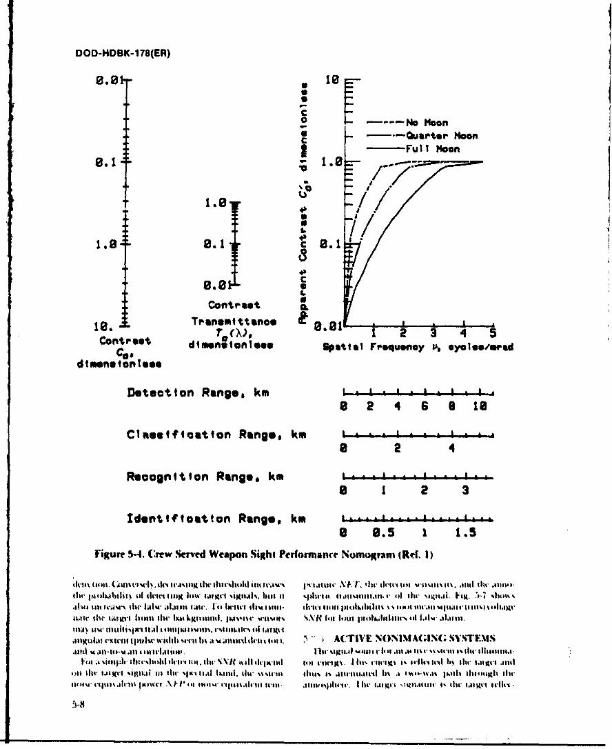
DOD-HDBK-1 78(ER) 1
Fu I IMo
L /
10. Tranotttsnce tCotrst d r~~~ s m,02 4 5
ca d~e~tonese patial Fequsnoy P. *ycleesmfred
Dteotton Range. km I t *
8 2 4 6 9 10
C1Rstficatton Range, km i .8 2 4
Recogn tton Ranges km -* tis 1 2 3
Identtf toatton Rang.e, km8 .9 .
Figure 5-4. Crew Served Weapon Sight Performance Nomogram (Rd. 1)
dl,11% tu .Mil - UM' '4% tkN 1l-J-IHiK tiltill Mbe 141141 4114 WA-.e % )tiu~-* til-t_ i- tat i gs i .1 tt s tiw .IS
ir pilIMb~Iiiti, III tvir- tifili *111tv w~v bi~u t Isibi t s t.11MMOMMs I , 111 111r NlitilI. hga. 7.7 fin'e.11 t -i s- slit Ifsl't .11111s wil. I'll Ih-1t i l tits- dsetat slmua is x ati 1CAllt 11. 111 Mgll %t~t shtlt4g
twtitIN- ttAIJI-I Iwuna the- 1tktlLni J~sc -uusv VIC las ttgslu~ss-a'iil-.iS5
.IKUt I.~tit u.luwiitt *-- l~ , ustuIsc ittii . ~A(TIVE NONINI AGING Ss'STEXIS1410s -A 40t-101-4t.10 4) 111i-I.1.t Ice. 1114- %s5liA wia 4tl 4- It,$ mt.t lt 4' %-te % ir 1 t ilt- 11111111.
V-u: t insIPIC thitat %11-11 -c 11 at:1 1. 111t- SNJ sl foot-gu ua-ps tH I II' its'-tn,x i itI 11 -it 1 1 iW li l4t mIti1d
oll w wixt-1 ifi~S 111 1114- %)i 11.11 1&1111I. 1i14- %%%t4-111 111%1% Si sit-flied tI .1 l.5 %t-S gIit 111146111t ts-ntew s-~u~ trt ~t~s .\I~P llIl a ~ a~sgidii ill5- . se .itlct x i Ugut -0;0u.1itie.- 1% 111- i..: Ics dirt
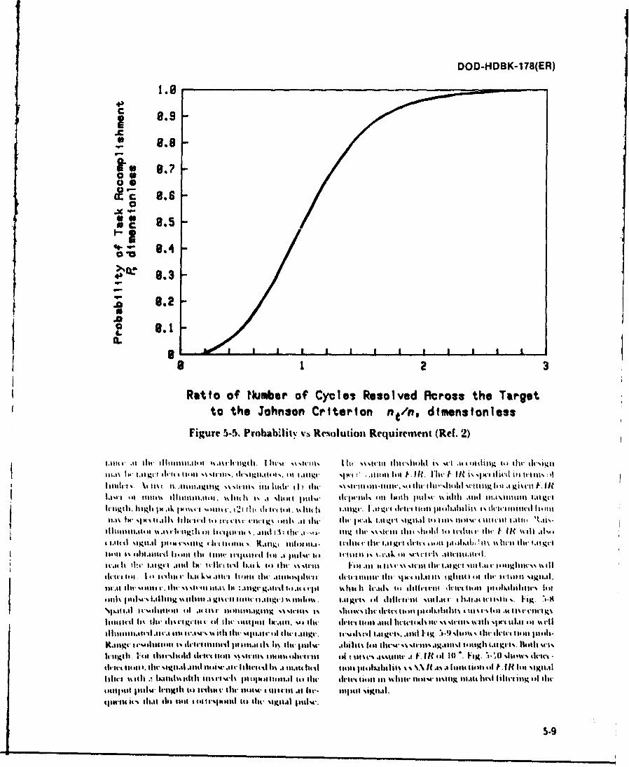
DOD-HDBK-1 78(ER)
1.10
4-
a-
C2 - 8.4
a C 8.3
8m .2a
81 1 t
Ratio of Number of Cycles Resolved Across the Targetto the Johnson Criterion ntloo dimensionless
Figure 5-5~. Probabiit vs Rtom-oution Requirement (Ref. 2)
gI I . I~ \~l4u 34 115 (. it,54' m l l% 4111 111t. 4I 5.114 34 11 ist- l hu O I . lti lId wtilg. lilt 1 Ki 'll Vt t I
ht51141 hIMIM jM.Ik 3H lil It~t 1. 1i A-it if I ~i' (Ir is 1 .414. fill 4r1 dilli't .ttat) t sd . 1 1 1d~ ii tii t- i iil
iitt-d . 14. 3 m'It 1"%%11 c li s 4t ~ sitie vt.t I 21t (1(dt lit ukIm I gv , 1.1 S t dtiv t W al ti l .13d di).ti % ith-i- lil i- 1W 1.1 lilt
11.1t IN, 41iat.4ti k Iit e,,titt4 Itst tu t114.114% 1011 k l sr O ,I NAg tt'. '.. rk to~ km\ t'i~ t alm. I w i 11it
4t-,. tt mglmr p,.ull*1Iilil 14,111gii i iiitih. e 411t 1 )1111, 34'lm th. r lmgt t ' t lt ktit14 4 tl 1jom .14 ' m 4 Stlit dw 1%'. I i
Iiit-tt.,ti it 1. 1q.I ari mil I'~l l . 111" l t ' I *.ut'ek .ul r rvh .114. it '
It-,1t It 1". 1.11mt-is .1141lt LIId'jirtt Ir )t k it '.11, N%wl I'lal tIf .N\% il w gv . 11 111t.i' v i
dult llt, titit-114 t Im L mi-Ilifti lit-illIrlli ir w Ibu lho 1%Igh ll tt O i ms t i 5.9d
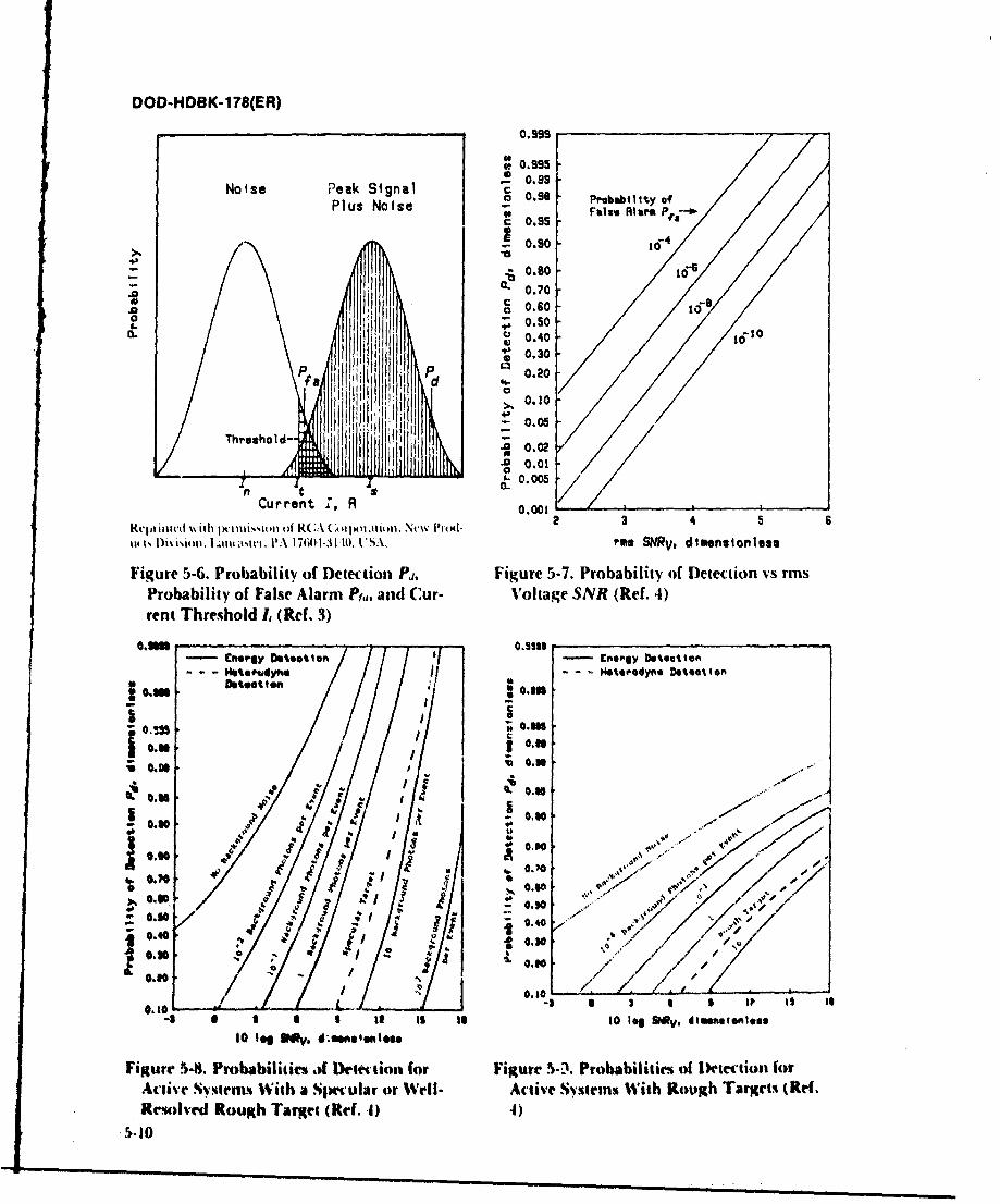
OOD-HDBK-1 78(ER)
0.998
.99
-0.99
Noise Peak SignalPlus Noise 0.95 Probaiito
-0.805s
- .~ 0.90
I 0.700.60 1-
I-~0.50 1S0.40 i1
*~0.30
p f
d
-~0.01
1 0. 0
Current :, R 0.001
Repinted with wiKIissionloi RCA~ Cttpiion, Nt-%% NP11 2 3 4 5 6
tut Di~ isiol.nta, I tii PA 1001-311 0. VS. rMs SV dimensionluss
Figure 5-6. Probability of Detection Pi, Figure 5-7. Probability of Detection vs rmsProbability of False Alarm Pf, and Cur- Voltage SNR (Ref. 4)rent Threshold 1, (Ref. 3)
0.SSU0.5133ener,.gy oteatton e nergy Detection
- --44.Pdynte II- - - Heterodyne. Deteast on
em Deatootten .
0.1m0.
J6 0..0
4 4 k
0.0.3
0.0~ .
0.1 Li ~ .0,@,
/103 1 t Is to 0 log B3 V, dI'~imeoles10 leg SMOy, d.es',1g
Figure 5-8. Probabilities,) Dewr~tion for Figure 5*Probabilities of IDetectiost forActive ~Symers With a Simtular or Well- Active Systeris With Rough Target% (Ref.Resolbved Rough Target (Ref. .1)
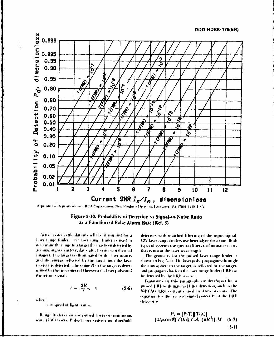
DOD-HDBK-1 78(ER)
S0.999Co00.9950 0.99c
*0.98
00.95
0.90Se y 4 A Y
c0.80Y X/ r//FIS-Vo 0.?0F
C 0.60*0.50
v 0.400.30
o 0.20
*~0.10
.60.050.0
to 0.01a. 1 2 3 4 5 6 7 S 9 10 11 12
Current SNR I3,/Ifl, dimensionlessI't~pi slud %il Is jMIIlis..,*m il 'ii O(thipa.Isiaa*iti Ntt%% hitti 'I, t% sis Om w 1.. wv, 11At ' I7e.01.1110 ii .
Figure 5-10. Probability of Drettion vs Siguaal-to.Noise Ratioas Function of False Alarm Rate (Ref. 3)
A i. i t % %ikI 4A411.1 oI.ui wI i ll~t IN, ilhilt e i sttIb .1 rc tot %%:fit 114 Iwd I, un *'fix o tilt illpili %4ii.lawl i g" Iilitdu I'l,- ;.Owl 1 111pv Iaidti a' u -cd It) CW .1%- LCi J igr filidti % uim.Iintvlwt% tin (Ititut lioii. &)(hil
th-14 inilit gt11 1 .111g 1.1. -n it m. I~M e tjil-oret Itl b Is% t% of M %6c Ii. i tw ~ taml lt Iitt~ 66 dit I il n 06161.11t t
dslai .ii1I~Uh %'.41I6'l kt~t ti 'ilil.r I1 t~6i ) thuA- % tia it . m 111 gVtnI 111 t i l OWI'ieA %- IMIR fimlithit'i
~and i til't Ki- uitrlt intl bs dwi i~italg i u ii i. O~w ;w d41i t ill aim - 1-~ 11, 1 lit' 1,14- i' tuI% I)itq)Ix1K;1t'% itlip19hi
Ilitiir 11% list- tinlt' islittv-. I lottwivil r''t' Lowt jmukcl .eid st~i tKhoall% bM4 L6 it ilawf faii4l. hasidni t I RI' it)dwu Iti %ttiIl: IRw drill it'1 I lit I .R I n rim.
g= 2Rt (r.o pICd I.R. Willi *ij. hrt filirtcs tiimno. m i t ilesi NuVA(. 1.KF ttmwiutd to" ill %Vriit%%%%r. ft,
J*4j;aiaj 14,1 i it' j#1tu taid ))WiP ijr I.K1~~ lint. i ll ia
%114111011101~hi. kill %.
Ratsigu hamuhrt t Ili i m pillted L...s ittilit41I1 6 1 I TA
wave law%. 1116A 1;v~l tim dilhol (ir-').W 5-7)
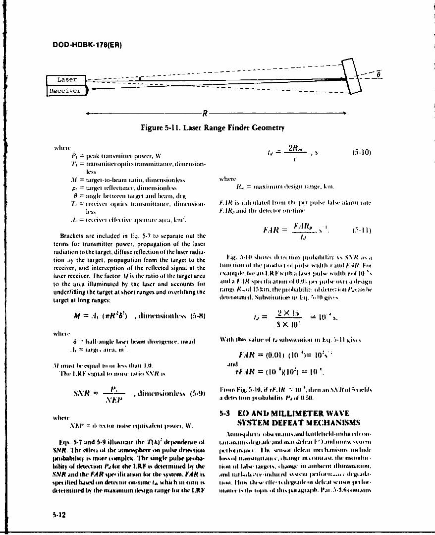
DOD-HDBK-178(ER)
R0
Figure 5-11. Laser Range Finder Geometry
where P,- ktasitrIte.WI = 2Rm S (5-10)
lessAl1 target-to-beain iat &o. dimeniless where
targegtt Itefletamt., dimlenisioniless 1?miaxiliii design I ;ngt., kinl.0 = anigle he-twev-1 targt Mid lt-ea1, (k~g
T, = we-el opti( 5 ti-tI)5i11ittaI1(e, (IinWIit4i)- 1K1 f is ttlttiatetI 11-4)11 thr lXi1 ;)tit. lalst. alaril n atteless F.1? anMd td~tew,-1 on-itite
=1 e w e ki 1 -i e -I k t iis a l sti to r e an a . k in .F A R = v 5 - 1Brackets arc included in E4. 5-7 to separate out the idIl
terms for transmitter power. propagation of' the laserradiation to the target. diffuse reflection of the laser radia- Fi.AOSodt(tl lojlll4%%-NII.ation oy the target. propagation from the target to the h.51 hw ke ii ihbl~~ ~tarcci~cr, and interception of the reflected signal at the 141 11 ) h rltto ~~~'wdhTand 1KiIt Fon
luser rceiser. I'hc factor it is the ratio tit the target area t-\aii, ll~ .mi l.RF with ai lase, ptils widith rill 10) ,to the area illuminated by' the laser and ;ccount% for '1i1t A -Ixt s lt dationt ult 0.01 pwi ptIN el sn.a dignmiunderfilling the target at short ranges and owelillhng the rag /%%o i, htthhii' f~lt~inI~z nI
target at long ranges: tltittel ti*tt"iiti 'JO g
3 x 1W,whic
6 111.11l-.0nngle LINAwi 1Iwann thsVVIMC-1. .. 1111 ",lilt tIs kalt' ts I~ I lsttt,#lFj I oi E,
"~' H' FAR =(0.01) (10-4)=1:~
%I l itw 1w 4etilal it) fit Ir%% Iiiti 1.0. JIM ali11c I.RF vgnlal its Ilisu tatiti SAWl 1% rFA It 1 ( ')~ 10 t
S R -!A- . th vit~ id t -'ss (5-9) hil Fig. II- 10. if rV.Ift - 10 111. 11 nl natN M\* of I s~krldI
Nk.P itt ti ioll11f)t)l)IIb11Ili oilf O.
5-3 E() ANt, MILLIMETER WAVEXI'd.eo 114t..as iittem .wrs. W. SVSTENI DEFEAT MtECHIANISM
Eifs. 5-7 and 5-9 illtitatr the TIA)" dkiwndine ti 1.4 11111,4111% thglaad I ,n.4s dlva. U ) .11141111,tis wsiinm*SNR, *1hr ellet ilf the jt11U%l)hctr t)3 tsoulM ticlctti 1 ~iltl 111tVIC 4 1111 WIltt thil4) liAlt 11114-111,111-011 141411441C
W10114bililY is MIMI cOMPIrit 'Met sillgir PuIM' PIOIJA lis i ;anun Itan41.1g.- olt 41nmtl.w, tilt- nntIIoHa4bilany (4 dkit't-tiot la Ica the I.RF is drtnmiotd 4- the niiu4fake Ill uIRts. Itag h 1 tetnallgr 11 .8tse14-1.SNR and the FAR qw' ,ii anitm list the %Vgrim. FAR is .sIl oL 6l i1-44It4e] ItIt%l- ifird based 4)3 detec tilt tilmv #.%. whi h Ill will~ is tiatl. I III%% the-m- 411-fI- t~-4114 i dtoc-f-an w-isl as fil ad-irmitied bv the maiiatuV &%isgn tasnlgt list the L.R1 lialt' vs 4% llt10)14 (d thlis fhlniagl. 111.1. 111114.1111
5-12
DOD-HDBK-178(ER)
dtvl(,t itea is ibiclls. q((k sumiiiiN guides that neai IR steicni h lave 1)001(1 wisiitiot whtil tilt lightt11d(aut w~linV it llartitilar. obstliazit mla; hav a lelis reduced. Surface xvettilig also miakes tilt targetlitg~igihle. miillol. o* pol)elttll': ildot celt oil the tIdlectiol of i' radiatioin Ill1orc spe(lli (glilliv).
1 )el lo )inaic of it giv ell 5(1101 ( lass. hIlis chanllges tile spatial dist iihulionl of dhe retil ur sizg-tiil and cat ises at wide liatige inl lai get rd lectanut, signals.
5-3.1 LOSS OF TRANSMITTANCE sonme of hc may saiturate aI laser rceiver althoughTile attenituattonl of passiv e tatrget iradiation or target otes are low enlough tf) remlainl Iundetected,
(otitllaSt by tilt atm osphiere t e.(Itl( c'5 the( atpparent targetSigiliatUr- Mid reSults inlloWer, Spat al resoluti11 on b 5-3.3 FALSE TARGETSp~assive imaging systemns and lower dletection probadnl- Obscurants may appevartas false targets to imagingit) for passive imaging and nonimaging systems. Foi- and ninliliaging paissive senlsors, anld to active sy'steis.ac(t i% C; StemsWI signal -to-noise rat1io and dettion prob- or they may increase the level of clUtter (target-likeability are-( reduced. Also lot, tlese SN stemlS thle efet of objects), whic-h mnakes target discrimination a mnore dif-obscuranis is nmore severe because the illuminator radi.- ficult and time-consumning prowess. H-ot spots inl exo-tionl must ttavers' thec path to the target, In- reflected t hermic smokes. high explosive (lIE) iuttitioti fire-11011n the target, andagail b e atItenlIate'd IW thitilt-ersen- bills, tulle flash. and burinilg vegetatlionl or vehiclesitig atmlosphlere, will appearl its potentlial tarlgets to) thermal systems.
whereas very hot sptots miay satturatae thet sensor. Thme5-3.2 CHANGE IN CONTRAST raiac aaiate withthe, phenomeiec %willtdegi ade
Atmvosphecric cotnstit uenits mayt da tge the apparent or defeat visuial and near. IR itnagers thiotagh c htterc oni as of a tat get n91 thliev witys ill addititon lo) causinig in trcxution anIesrstttn Bright l ights aid V2tranlsmnittani 0 lo~sses. A111itmmt lighit tlla be st-atvetec sensor~ sattinat ion (and thlt concurrent-t gret [lash) iltito thlt- sensor field of view ( FOV ). il lutninator etmerg - night %Vill USCa te tlil nutobSCer vet tostiffec a1 Itc'tnpX-mont- 1w macksattet ed into the sensor FOX', anid thet tary' loiss oll vistial niighit aaptation.
ac( till tat get signat tate maly be c haniged. Wi ckv alte lilto tt~e 'tt tdiaicit [ i tS1tc tteig of aienthii illutinlationl into the st-tisot dense-A ohsc urattt may c.aus~e a fls%( tatget cletec lionl or it
allc t ptitat I;viibl an nat R s sems. I'v_. those lalm. a an1gi reah tug.NItems that amvsnsta to lik-ht leel. N4ukltiple soattec
nag oil ttgoetiadiatitg ittta tilt wtsanm F(X )Vin dtnse 5-. (:HAN(;E IN AMIIENTolsm tnlm, atuts ana ml m. dt I thle mushltiol lit % isala', ILLI'M INATION
%a ktivititg lo at a'k e tllinm tta vi t'~. t% I at t altll a t 1tsjthei hc taa'imea of Jlaiad th114 phllslbtlittts Enee g 11.ta Lv ,mawed title) lista eni -et o. %vihe i-aln Alt liltat tutu, th icam a it da .a l 11111%
ti.1tt1 UIt 11as ia-igi anid 111.1 lilt raw lit- VII oIe at litet ahneheWttituo 'fsptileohtan*sal.ttgr ItIttelet . t movtS ll m 1.tttga 1qaxlt ttgs% II slit- silit:~ ttits li h hm'l dmcca'a stl acid 1: 5stn
11% 111 111 161 tal .aail-t tttg ItI lant .1 dense, oism fi l ir it lo w r em ills. u u s t a sig le. tel marthe d w s h e t~c c i;aiatmlgalsewelth t ill lw 11tled jtsptl shajw'mv sgi t4o t'rri aseth -.-ht Irvs
alett mntt tn 111.t% 1 .111%4- .ttt 1 .141 1.1RI tat 1m 11,14 an e 'tit Iltl
In Iu t-I meal i ttua 11laste%l m ist Iuamis I wilti ottII- all. tlo-stg. 5-. TV'RKLEN(:E101t11t stuial sha' h r11 aste aot ht 1111nas1il, Atimosphi tuililiu a .l-t1 %is isa- IsvihItlot i C
Its% Lmto oae 4.teaso a ttttsslte tiat k tna tin thr clesagismtia ImAtaim lt .411 I lita ia n amatmaspl~h at 14rttepal.tua%skgtia tan hintrAk lit k. 4,111W' 4b.11Mtmg ill11 t 11m4 Chide 101c~.11101 tea 1111 t ,it.
lit Ins .1 tag u i e tta .,ta Iai Ill IstraI- 11111 u tuttI ;atIsAt. 1o,11hleenaa ella-at' Ate nmanse wwt, Atmi hi illa' 4-1 light~ t li-%1 nlaum isesaaaase g. h.s~slnthstdaetinttIaiui i lot .1411%v~
t111V% anIll 11 -Ilt tl 11a411411. Ill t1he' that111J ,ti lkt Iatlite i Is iri iasw tWit~t Ad w ttA-aita. and a %,Itl.a aunlin VGIasla' ins1t Jlatrt1Wim a l Jan t VIe .1114 imia L tilliam itiat1eck7JWtsl-tIUU htialtirtlil Ilitk tit0't4*t%;
Klianid~a atait .114 tail 11 il mst. a t .4 getial-Tiahl Ia. ill ths- mvaatstaiaia' Andi mrenrth tl11lutnix 4eIWag
Itut-Ic's K1.1%. Ai i"h a-Is ha-at-d Vc-ettIeIss., %119a .It as tk IX-4011setmchaas lw %h trig 4.91C sus X-,atm 49a-t'tte.141% .snI lithaeti- V1n1 ct)1 as-1a Is-ll t.41111. Will 0s0141 Ittausd UVA114le- Atml .a is nft caIP e .inaC Aie~ 114%And ts.44LIISMt lNa-ttcm lt elms' tat Itatacteshm tilt, PAssIsa- % sImAI Ando Aftaa saVa il l 1. OI situgeug sit mtbuk-iaa atu% %Auwa
DOD-HDBK-1 78(ER)
somec loss oIf rctsoltl i 4 ol i b lring; this eficti tan Ix- sigilallit C., lo 6 d sights anld I Slt-iciis. ()I ,1:4
v.iewed as an1 atmnospheic Ait.F dirgradLtion. wilci t'cc P, lot lasrstt'ii1.Tisk:
5-3.6 POLARIZATION it. il t4)ask, ~. veclo i itlt4IlicaIt'til
Sct tering ol .diatioii h%. denise Ineia restilts ill It. Range 441 414 lptalti IitN tiie til
lilnaion. uha diet rs Fod .til reitdiatn 1, th6 in- c I ia-t S i. lp ill tilt aIt lille aljt. ii idlilltll
il( 1101 itilp)rlilit. I lt) t'Vt. for' ptdailt'd .uti. . Dll ti llilic I;Ii get si1glia Ial Ih %li t'15 4
54 41i~'..sti It.1' 5tIi~ laer atI 1111W ~*st'IIs.jN4tl~/a-3. l-tt'i liiit so-liso 1 I -144 lldilut wlelil ill -
ion efcts Ia I ik Iic'I .%ra a larIgetI d ivc i i nalui t. Ft 4! ix ... , I SAW les c 411110411.
liltsc senlsor' an' ailtllspihc' it-iildluicd change. ill IM dar- D* lt-wl1 145*144 itiilln *lt411istt-st ii iwi -
/alioll~~~Itto .41 hil114 tilamioti' S Il h%4ulllao alilol(lll'.444 1441 1, 44.i14I t - .1gil .,'.iciu,. Niti cactI.t7 IR m DEFEATic It EItoNIS TABLES .. iv 'Il 4.44 .4-1 . ill 114 541544(1441 4olalp Mis.it. .illu itic
i~~ttiog ~.t sta it 4154 m4t4 liltl llciiisut ili 1144-l' i l.e l llt% 14 140 44414.4 l., ti , .11.4 tc t licl Il
,4s'.ttt ~ ~ ~ ~ ~ ~ ~ ~ ~ ~ ~ ~ ~ ~ ( I~ttt I.tl I~t It I4)5 1.11 10.1 . 411 tli saI 4 ie toillt w4 I s1 114 n Iw414'. lI'l lt,11 It4' I 414 144lll
ItS tA .~c t te leit 114 Ilat~sll Btt 4* 454 *titl 1.1It-4ill" ttal ( . 1i 4' e M t u %ciIl. lit litii '.44 . ilt i a ta
.4. DEFESTAT IEA M TBLES sig. I t I bat I). iI t - I wi ( )a "TIOP1-2a tI ERI it'.ltttl ~liiti tt. ~ 111. ~' tg.ph tltt'4 1,1 itt N I)l SMOKEilt' ') c0I I
t454 441 ilia 4114 '.'I 1 (t11 41111144 la l t'*1 . 41154s an habc.I Il h114lala ilv lcc %%11 111i .0 1.1 1-
fi 11 HIM -~if 4 01,4.11ta111MMSt'. t4ll t W 11 ,1 IX. lil11 ,1 C.1ill 1K )Il , 1 .- ., 11 %u IIIdr1 1 44 1 1 I~t I~ l it 44.) t i t i 4. 4 5sIjwililt 1%,11c m11111 h i' c % Ioo iaie d t it414 .I,,e , I Iu~ It-111.1 tit~i~Ittit4I.I .n~t ',' ~ l illi
.1-11 t 11ltl4 411,-'I -Its "1414m' thu j-lm i ltI llt 111alt 111. c*vIoltl 11c i i$a I - %%tIlA . l d ld
tIti 1-n vil u 4 lilt t', 4 h u .11o~ 1 14 .it .1 4411 t111t'.144 U-1 1 1i-I tIh tvtl'ItNil l tat l 1aiI tti-
(1a - 'i4 tti t il,41 g4 siI -ll te % - u liltl4 tit, As till'.NJ olI 1 mliltli e IN i 11 \IN
slt llc '. It d ia 1( 14, 1 l. .1 4'.ttt li . 414 Imltasse t lilt .1 (11 114. Ill4 4 I I .11 7 44 . Ill14 tilt -A t i II kiti.4
% It1.,L i)u 4 4111'I (leIR ase tt 111 114) I .14 IM111111w4 dvt. I ' ") ill '-. ,t11 it-~ l .l.1t I hW 1101 I * 11tll
tit lilt~ . .it-I ill 11.1u it 1lt aitto l ist 1) ' 1 .1it I
it.~~11b~tl dwta njt~ I44.IMt1 l%)latp4 lit. lisc4i.44 %* ok.1 I* 1 1.614.1144
5-1'. ILLSTATV PROBLEMSfh 5.,-4)1.44%\C at4.4li~4l 4. I .4)1). i INIC LA ATM2 I itt'.4 ~ ~ ~ 11' pala41.1411 . I .1) SMOK4 d (C.%4'Il.ili h .Ol
.h% 1 .1 14 it i 111 11 I41 II Iob 1kiq tlBit ' 14. Iii 4 -t o .4 41 its , t o, lit I .4 1 1414 c h mI ItL t 114 l
v. I .41 iv 014 IL. 11 11itt 0 ,1.1 11141 I A mple Ii .14114445 I1 .~tt lit% pl b i -l U~t~ j j - til Lustc o iW ith 1 414,1 1 ht1141' m11' .its.ts1i.1l-i 111 aw) 1'.4,444.4
I14 t41-1 11111111 .1 *o~u L141114106 11lit- t1114: 11%4* 14uo-il it %.4 ' 44 4ti4t41 % 4 ~l1t H I L1
11111 '1 tuI ilimt 1111144 Iitm 11,4441% 1, -Al l W 11 4 1 oa14 1.11s .lttt~ttl ~iu t' I .14
111-0 41141Illt11% 100141tltl -0.1 5411 C w to y
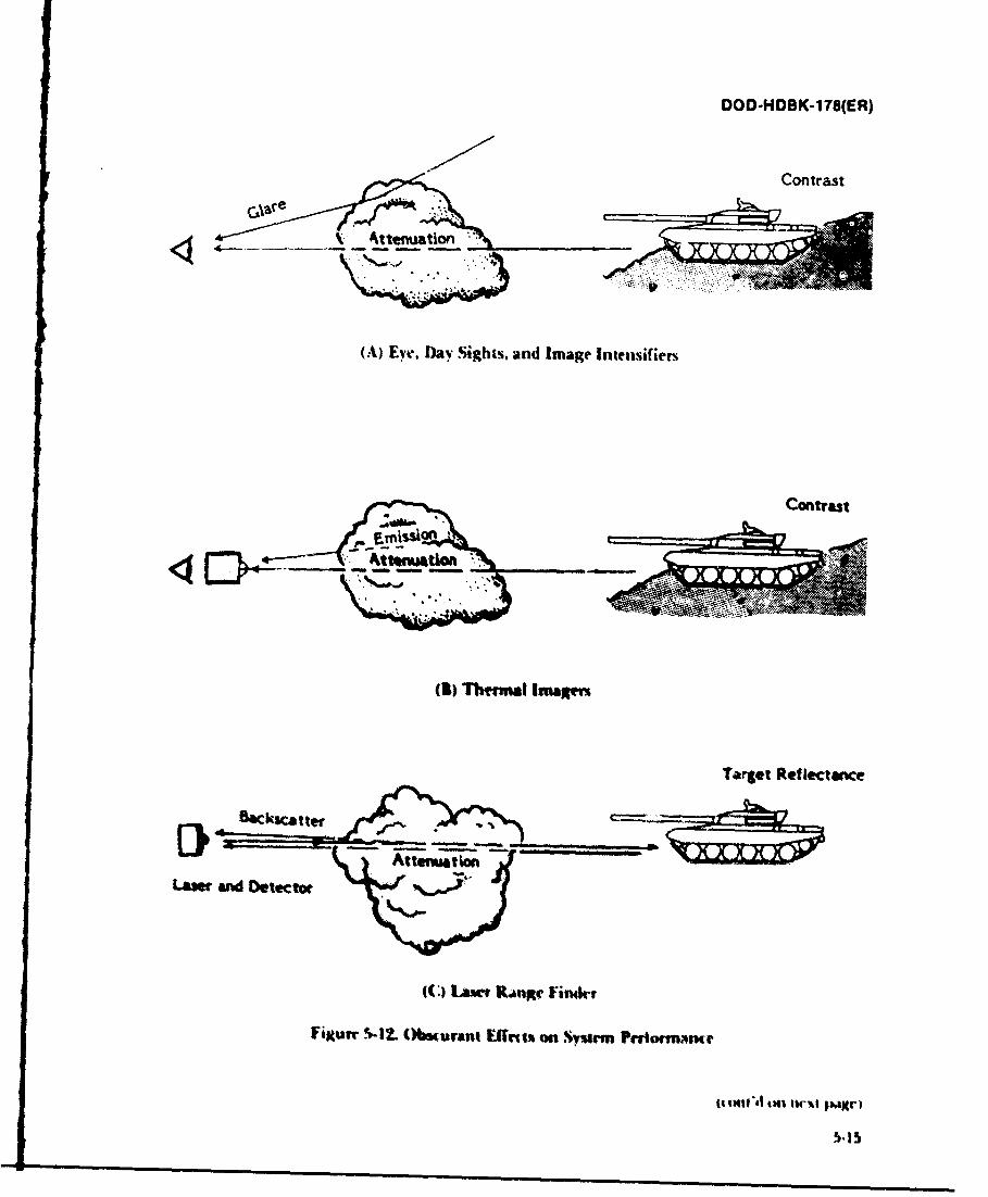
0OD-HOBK-178(ER)
Contrast
GlareRfIetwc
-Attenution.
(A)e Eve, Daye SihstadIagneniir
((.Tage Reflectanceun~r
Filtun r-t2. (Nmurant Effrin on Syrm prownmn
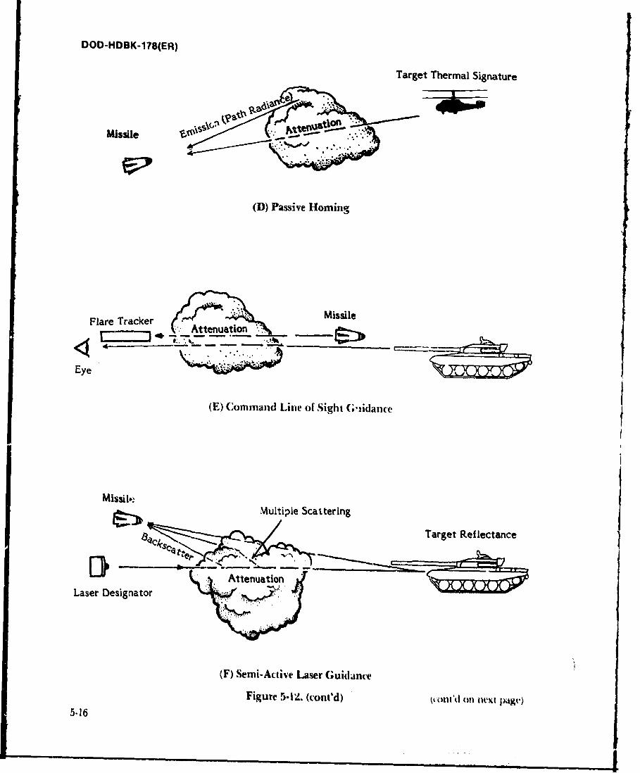
DOD-HDBK-178(ER)
Target Thermal Signature
NO--
Missile --
(D) Passive Homing
MissileFlare Tracker Ateatn
Eye
(E) Command Line of Sight G;iidarice
Multiple Scattering
Target Reflectance
Laser Designator
(F) Senii-Acuive Laser Guidatnt-e
Figure 5-2 (cont'd) t.& lttd oil Ilxt jxkgv')5-16
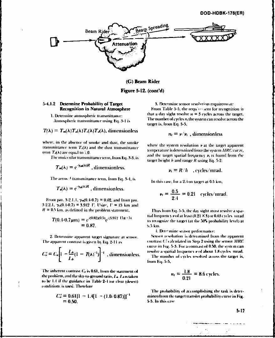
DOD-HDBK-1 78(ER)
f ~ .*5ed" Spreading~Beam Rde~ ~~e ~ I
(G) Beam Rider
Figure 5-12. (cont'd)
5-4.1.2 Determine Probability of Target 3. FDetevinine senlsor. iesoli'tjonl rt-quiretneCAttRecognition in Natural Atmosphere From Ta.ble 5-5, the requ~ 1, ien for- recognition is
L. Detenilule atittosphet it rnc ltace that a day sight resolve na = 3 cycles across the target.Atitiosplterk iraiwitfittaittt' itisig Eq. 3-1 isw nTh e ritt of cycles Pi, thle systemn c-an resolve across the
target is, frot Eq. 5-5,T(X) = T(X)T(X)T,(?X)TAA), (litlelisolessli = yvv . dinensionless
where, inl thet absenrce of smnoke and tlust. tile siiiokt where the systemi resoltitiont & at thet target apparenttranismiittance terni T,( A) and thet dust transmrittanice telika It iterilld froml fryiilARore
1'lw moiA'uare trasaitae teo: frmAt.33 anld the target spatial frCeItae)Cy Pt Is founld froml theTheilliekOartrasirittiwewrii, roii Ei. -3,is target height It and rantge R uisinig Eq. 5-2:
T,(,\) =' ,V~Af dimi-ensionless. Pt= R/b , cycles/nirad.
jThe aeros.-! transmiittalttt' termn. from FEq. 3-4. is Ini this tase, lot a 2.4-m: targrt at 0.5 kml.
T.(X = C**O()1 , inw11nsion less.0.
F:~ ~ ~ ~ ~ ~ ~ ~ ~ ~~~V =r 0.5l =....yOIO7 .2 nIitn ~r 0.21 (ycles/ttlrad.
1,2.2.1. -y.. 10.7) = 3.912 1'. t Isiv; V = 15 kill andI? = 0.5 km.l .as definedi inl th prtabil statemlenit. 1tihs 11011 Eq.-5-5. tile day Sight mntast tet4lv a spia-
e (t0.02 X0~)i 3 )l " , 15 tia It t t v volat levst 0.21 I ) or 0J-t3 cO It im adrI(0.'1-0.7pm) C to 4et ogtiie thelt Wget (at tile 50% pIkobability lvel) at
=0.87. .skil.
2, Dviet inti aIpparent taiget sigiittrth at wsotb %witsttl it-M41ittiott is, (lt-teli ieti 114111 thle apprentI'he appatetc (0ttast isgi~vii by Eq. 2-Il1. tittastlt taitvtI inl !Stel 211i tilt- seno MlU:
r~~ 1 ve it nI-I. 5.3. Fol at4 outllast of 0.50. thle Cytw all=~V0~ a % di,'t~ks re1l41 ptial heqllitat% v to abibilt 1,1 ('Vt It's tittad.C. C , 71A)" thinltttlke $d te t tst AI at It)'.% tilt ltrge i%,
1 1.6 1 roitl Fi. 5-5.
ETe inherviit t otrast c. is 0,61. Iton,, thle statellivil of ti _1____6_ycv%
II tilt t. the sky-io-gtoutiu ratio. L*a L. Is taken 0.21- .6(yeit, beI 1A if the guitkint v in% table 2A1 tor ( ra (desert)*towditiot' is kied. 'Ilweie
'1h1 jpttlbabiity of at tmplisl ile tht tak i% det-C'=0.6111 - 1 .4[1 -(1 .0i 0,87)11"' Mite uM- Mh th get 11tansler rbbltyt t Fig.
=0.0 5-5. Ink this. easet
5~-17
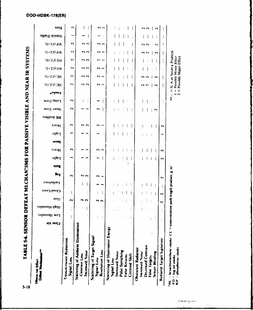
DOD-HDBK-178(ER)
S~~~~3qa NI -I 111 l -
(I djl (A C1 N C4 I I
0.4.4
rp (I =I))H o ~ 11' 0 H ~ EN ell eill
U~~JUY N 1141 aii
__ £ElUv 311
0
z a
I-ILLi.C
z
a~ c rU, Z9 1i 51
.LAo ~.
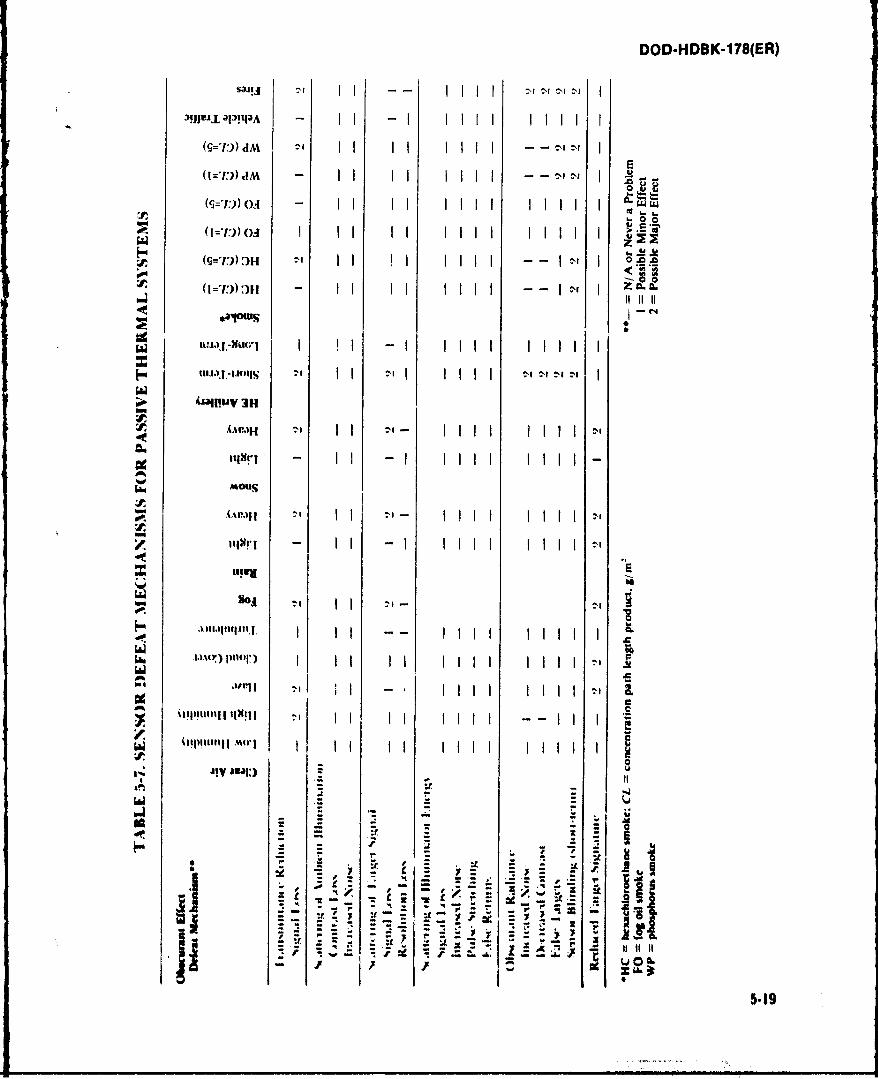
DOD-HDBK-1 78(ER)
il 2-i It O"111 111
UIUt.
- II Ii Iil I-'Iull I
JIV A111,10 i
GoUU~ dZ
.w*
IIE L..)J~IU~J I ! -i lii lii2
uI.6.)I.UOIIN dII I
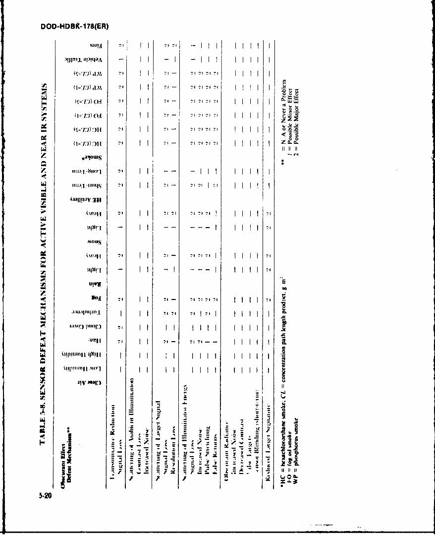
DOD-HDBit-178(ER)
0(=,I))J am 71i :AT
o.4 U LW)
(~~=I))OA A
:I T1 1 z LL
11 111,
3*1
II -- -III 1111
III.I..K ts II I I I
lbv
i 3pimil 1 IIlil
.1bIJ~flpflj I I I I I Ijag
5-20
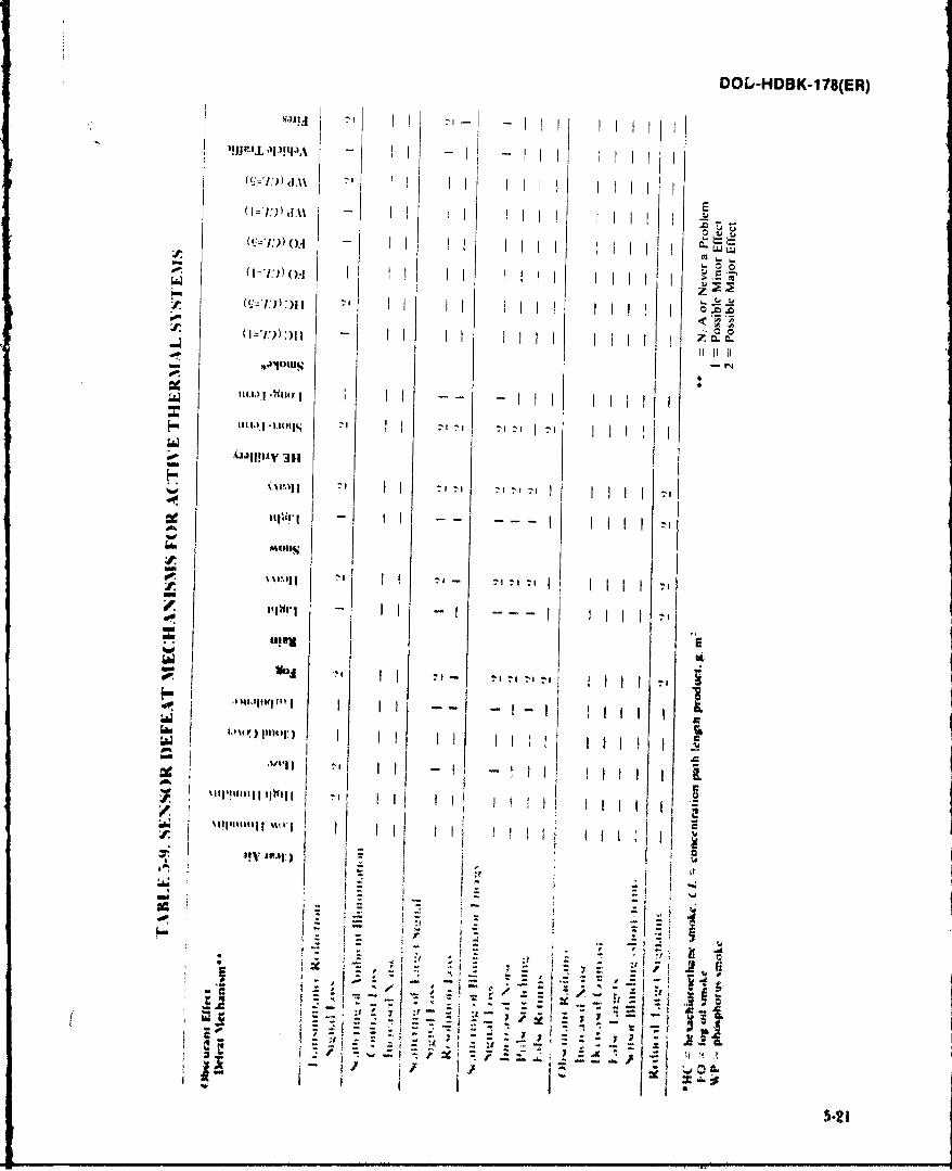
DOL,-HDBK-1 78(ER)
)IJJL'IJ apitla'k - II
-N IloI.I
:,I n
U!00
*A T i
16m
as
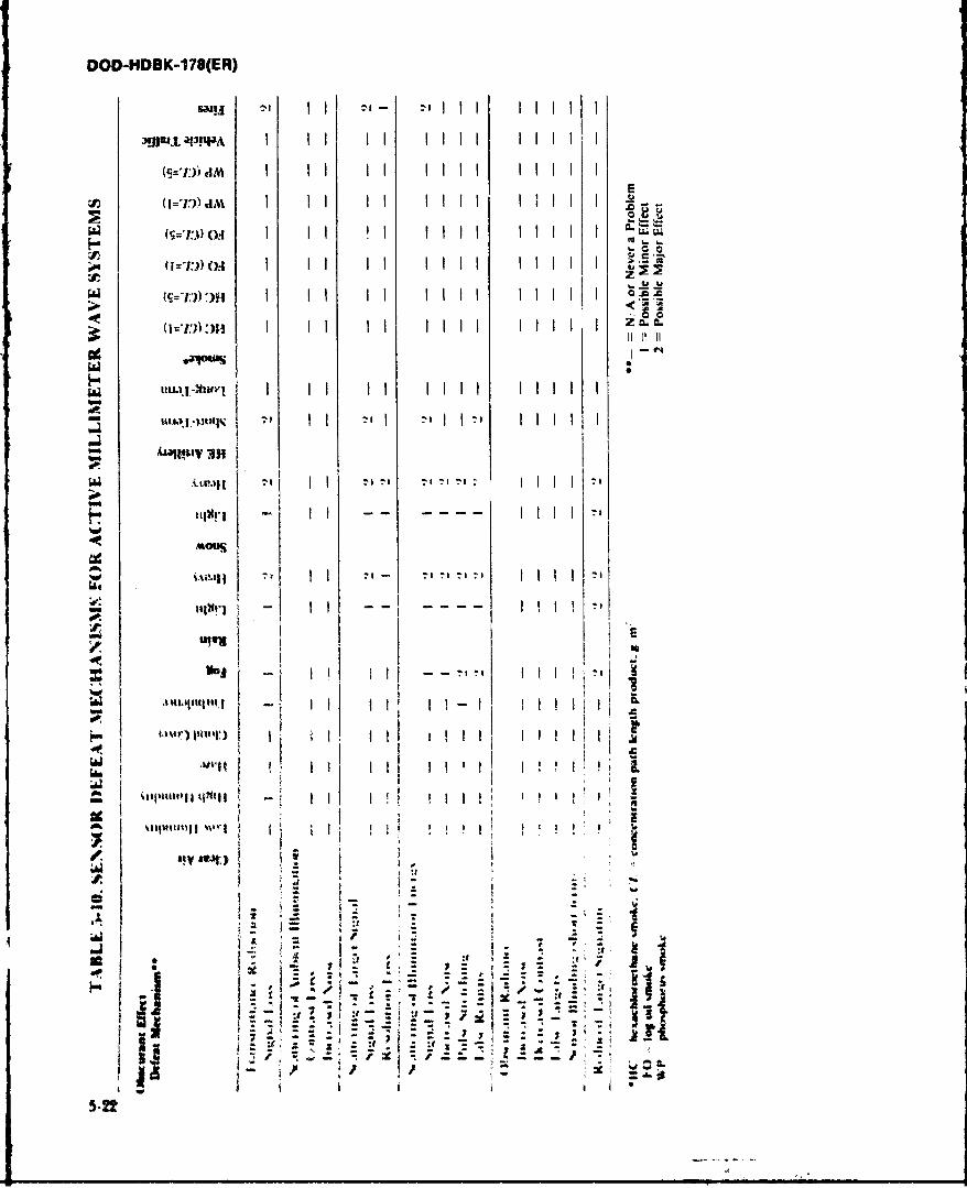
DOD-HDBK-178(ER)
Bij a' 'III 111
~ I I II liii 111 E
I I I t~l 111O= -r) o.4
I II II ~lt 1111 ..
cetU
I I IIIlwW
I I I I I I
MOtES
Iw I t"IIII'l~.~
130'rti) %ia .,
wimijll mi
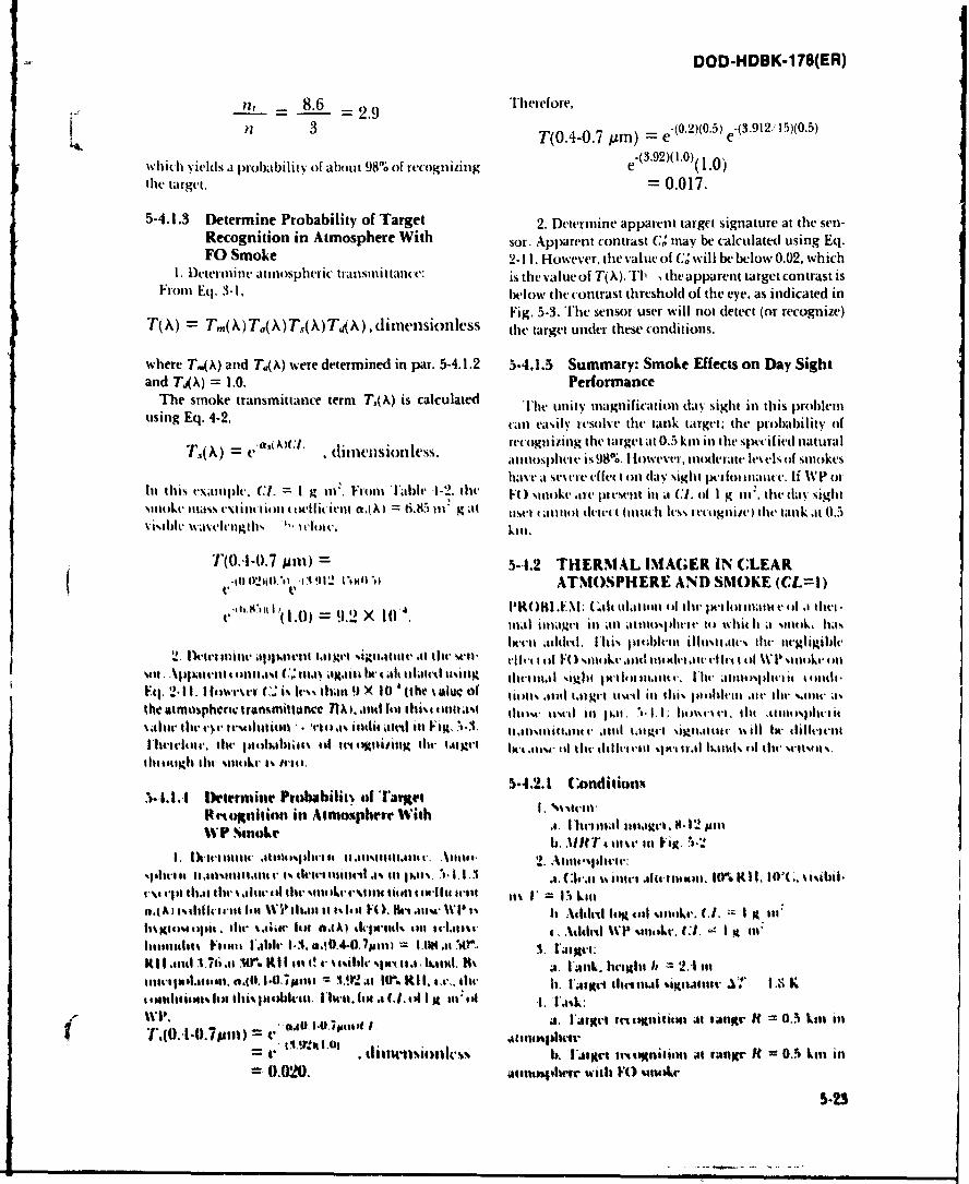
DOD-HDBK-1 78(ER)
=t 8.6 =29Therefore,
n 3 ~T(0.4-O.7 prn) = e-(0 .2 )(0 .5 e*(3.912 A 15)(0.5)
Which yields(S a prob~abilit%- of about 98% Of rec(Ognlizing e'39)10 (1.0)tile target. = 0.017.
5-4.1.3 Determine Probability of Target 2. Determine apparent target signature at the sen-Recognition in Atmosphere With sor. Apparent contrast G' mnay be calculated using Eq.FO Smoke 2-I 1. However, the value of Ct will be below 0.02, which
L. Determine atmiospheric transinittanc e: is the value of T(A).11l the apparent target contrast isFrom Eq. 3-I1. below the contrast threshold of the eye, as indicated in
Fig. 5.3. The sensor user will not detect (or recognize)T(X) = Tm(X) Ta(,\) T(X) TAiX) ,d i metflsion less thle target under these conditions.
where T,(*) and Td(Ak) were determined in par. 5-4.1.2 5-4.1.5 Summary: Smoke Effects on Day Sightand TX4A) = 1.0. Performance
The smoke transmittance term~ T,(A) is calculated Thew unity magnification day sight in this problenlusing Eq. 4-2. tan easily it-solve thlt tank target; the Probability of
S.t. rec-ognizing the target at 0.5 kil in thle spectifiedt natural,Tc', X). llen1slt)le's, a tnousp~her is 98%. 1Ilowevei, modlerate lvels of smnokes
Itave at severe effectI on day sightI peR-fiti 111;111(. If WVp otIn this examle. (C1. =I g tit. Front Table I1-2. thet F0( sm ar iv I esent in at CL ci I g tin* thet day sightsmioke imass emit in I Hi ifat i,( A) =6.85 Ii' g at MC eit 11 ant detet I (Ititc let Iv.%It ogitiz~e) (lte tanlk at 10.5
wie ie svaelngh% ,, 1lot e. kill.
T(0.Il-0.7 pum) =541.2 THERMAL IMAGER MN CLEARV'0.41'201t.1 v -091 1ttill,' ATMOSPHERE AND SMOKE (CL=I)
0e I~.0) = 9.2 X 10 4. IlR( )H~L M: .Gaitillatioan ofl thv Ilaima. ) a the,.m1at lilagcl III all atIiicis)tiei e to whit It a silil, has--tx-iecti achtd. Ibi6% poi ll illteIjt le the netgligibile
2. lMtctriim a.I~it t tat get ti tuit, -it tilt, cwii- vi*vi il F0 -.1111 1k t lilt c r.1 I il W I' %mt $Lv btmil ou11 t l t .t atlk1 t.tlts Gist111,1\ege~w lot-11' itimit Ihal- atn1141%iclit it ldFi.2.11. I Iotwt-vi- .' i% t.*s% thikit!) X 10 '(the % aluc of tktkt '410 talt etvr l liltlts i villm atI li w it, 3%
the tmosphtni. transimittuace 71 .a nt, am i Ilti$% 41111;4% 11111. tovil lit 1,11. 1. 1. 1 ;ewc ti v 4. lilt .itlot$% itei ittolttic thr 4. Irvitti till -g - s mlt atl ill Fig.' A. 1411isami ittat ia*anld t.t get signtat mv ill ha- ifliviteietItloiiv the li a'hltiits 4 Intignizinm lit- tmigei Ir K.aimA ol tht- 4ch1Il cotK- tm I at hands of the wltlln '
thatacighi tilv %si 1%trll
5-4.2.1 Conditionx
Reudoinhiio in Aimmsphear With . Iitial iae.A 2p
1 . v ~ l i l t I l - .A l l i l . t a e s i n i: .
eImAIIt that the saint mat lhv s.114kerltill lifomn 4 a-It trill it l 1, = Ii kl".~Al isilicienl t an 1w~'ta it ta F(o M, Ik-alA Mt , ' 1% 1b A4141,11 log atl siitaik. CI. =I lit:
tiigiuas r amta.iii s in 0.00 ath IMtl1)141 toll 4.ttiii , Addrd %.VPIlitlakv. C1,.- I g lit'K tisi ..nl V17is.m I'ait 1-3. e .0447sihh =lu ttAi aut r. ilg14111.41lst1176.11 Urlati .1 .04O ?sui 1161at14(.1 A.. I'lk.lbiglit h - 21 intilliteijiiiltil. 0.01. =~ipue 1.a Htr. Kit, se.". lit-eI.lie icwetsguce ~ I Ks lottlItiotis lot lit% jnobt.ivil t'iva. fi .1. 14 ohI i li I.l's
Wil I*.1 I.01h~mm it . l'Argiea- trititliitio at "Ilr It= 0.3 kill illt r(0.'I.0.7Puif) 'AI 10%l~plair(fiY..rmitltiv..j h. I'trt eecnxluml ilt raegr it = 0.3 Lest int
=0.020. ail"I"hIr Witli F() anUkA-
5-23
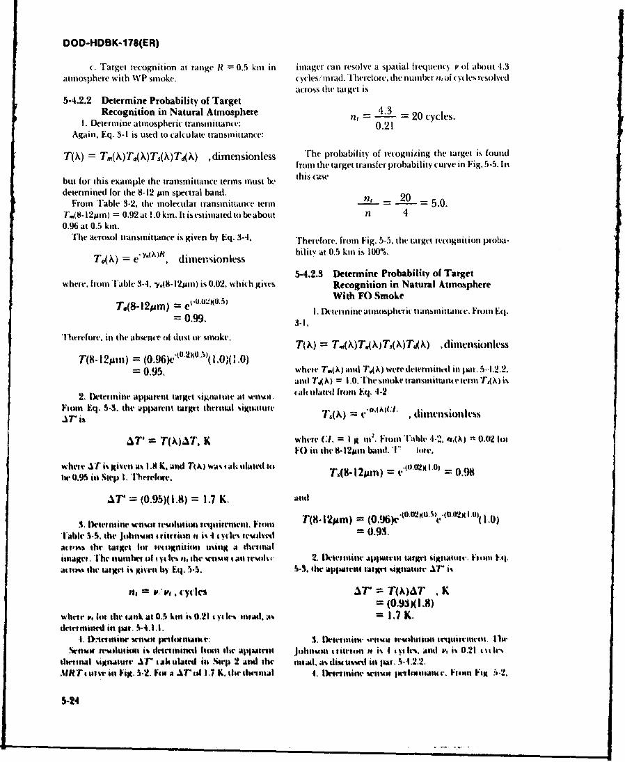
DOD-HDBK-178(ER)
c. Target recognition at range R = 0.5 km in imager can resolve a spatial frequeny v of about t.3atmosphere with WP smoke. cycles/nmrad. Therefore, the number n, of (yles resolved
atross the( target is
5-4.2.2 Determine Probability of Target
Recognition in Natural Atmosphere n, -- 4. = 20 cycles.I. Determine atmospheric transmittance: 0.21
Again, Eq. 3-1 is used to calculate transmittance:
T(X) = T,(X)Ta'(X)Ts(X)T X) ,dimensionless TFhe probability of recognizing the target is found
from the target transfer pro)ability curve in Fig. 5-5. In
but for this example the transmittance terms must I, this case
determined for the 8-12 pm spectral band. - 20From Table 3-2, the molecular transmittance term _ 5.0.
T.(8-12pm) = 0.92 at !.0 kin. It is estimated to be about nl 40.96 at 0.5 kin.
The aerosol transmittance is given by Eq. 3-4, Therefore. from Fig. 5-5, the target rcognition proba-
T() = " dimensionless bilit: at 0.5 km is 100%.
5-4.2.3 Determine Probability of Targetwhere. from Table 3-4. y.(8-12pum) is 0.02, which gives Recognition in Natural Atmosphere
T.(8-12pm) = etuA121(03) I.With FO Smoke
=te. lktrmine atmospheric trausnittaie. From Eq,
Therefore. in the absewe of dust or smoke. T() = T.(,)T(X)T()T 4 , ,dinensionless
T(8- 12Mum) = (0 .9 6 )'01O.5))( I .0)( .0)= 0.95. where T.(X) and TK) were determined in pal. 5.4.2.2.
and T4A) = 1.0. The sutoke transmnittanttv teri T,(X) is
2. tD-ternintir apparelit target signltlle at Wlol, (haltdatl front Eq. 4-2
Fim Eq. 5.3, the apparent target thtrnal ,ignatute tA)1t,a7" i% T"() d " ' ; " ,timn)sioless
AT' = T(W T. K where CI. = I g In. Fronl 'able-I.. o.(A) 0.02 lotFO in te 8- 12pm basid. Tl' hor
wherieA i given as 1.8 K. atid Tto wAs imk ulati tlo ,T.8-2pm) = v.10MX 1.0) = 0. 9ihl 0,95 int step I. 1wtritrT.
AT' = (0.95)(1.8) = I I K. ald
3. li)trilhew v'n resdutitmIjtiiwt t. Fnnt T(I- 12Mm) (O96)cle (ttutlot 1.0)Tablr 5.5, the jtdlnui tritrtim to i% 4 4 t .l teu)lv" = 0.93.agrtos the talgr lot I rognllt tsinig a 4lhrtltalitnage:. 11hC nUlthtl Of Iy ls IM f. the Wrlul I all trMldc 2. 11)ietiiaw apparntlt target signaturt., F-ibin Eq,
atIf)%% the larget is given by El._5.5. s-3. Iltappatmt target l tigtatUtr r i%
f. = V,, v, cycks aTr T(K)AT , K
whrr ,, lot the tank at 0.5 ktn i% 0.21 t y Im, trad. as = 1 .7 K.tlritniinrd in par. 5.4.1.L
'I. Ml.'einiaw seln pollualut: 3. fleitranine -.1atwif Irtanueti~x 1114renei.en reus-lutiot is tlrtmincd itnit tw aptre.tt Johoson a sirtim is i% .1 tt Ir%. and ', i% 0.21 t I-
thrlmal igmnluor '" ahtulateid in %tel 2 andl tie 11ad. A% diM tasMt in l .p -1.22..AIHT Huint ml Fig. 5.2. o1t a a.rt 1.7 I. dit dictoal 1. I)etiminea otro Ielo.mtr. Fitn Fix :-2.
5-24
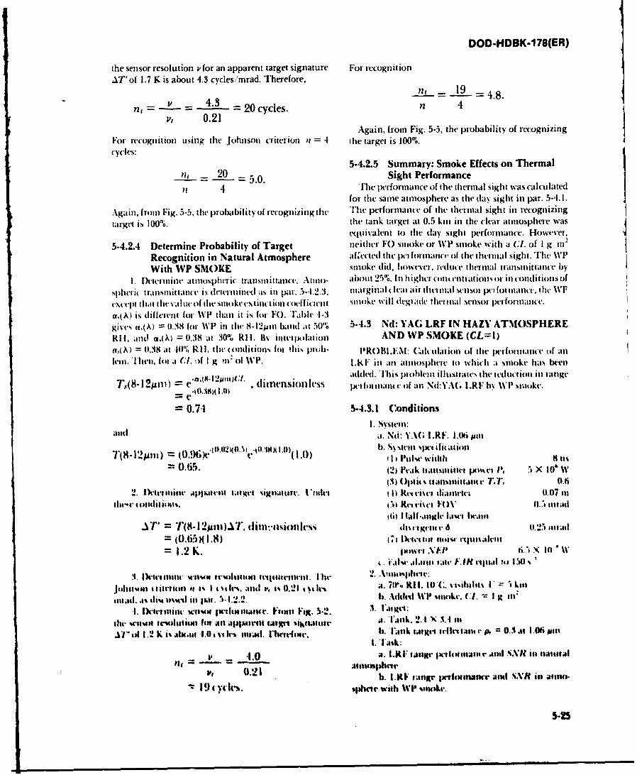
DOD-I4DBK-1 78(ER)
the sensor resolution v for an apparent target signature For recognit ionAT'of 1.7 K is about 4.3 cycles/mrad. Therefore,
= - 4.3 n, - 19 = 4.8.
n ~~0.21 =2 yls
Again, fromn Fig. 5-5, the probability of recognizingFor recognition using the Johnson criterion n = 4 the target is 100%.cycles:
pit - 205-4.2.5 Summary: Smoke Effects on Thermal_= 5.0. Sight Performance
4 rh4 performiance of the thermial sight was calculated1for the samne atinosphere as the dayt sight in par. 5A4.1.
Again, fromn Fig. 5-5. the probability of recogniiing the Th perforiflatle of thle thermnal sight in recognizingtarget is 100%. the tank target at 0.5 kiul tin the (lear atinosphere was
equivalent to the day sight performnance. However,
5-4.2.4 Determine Probability of Target neither FO) sinoke or %VP smnoke with a (I. of I g in'
Recognition in Natural Atmosphere atf.ected thv pelnforillatict of ithe' thennal sight. The %VPWith WP SMOKE smnoke did, h owe~er. redute i herinal transmiittance by
1.Peterinine tmiospher i tstuittatiwe. Atino- abouit 25%'. In i higheri (ton(entrajtions or inl condlitions of
spheti( transmnittance i~s dreerined as in par. 5-1.2.3, mlarginal (l Iea I air t he (,I 11.1SenSor pt for imuancv. t he WVF
cxctipt thamt the value of the smnoktexetinction coeffit it-lit sino ke will degradev thet inal sensor pet (ormmnaice.a,{ A) is different filr %VP than it is for FO). Table -1-3gi~te% iv (A) == .38 forl WVP inl ili 8-i1uamm hand att )0"0 5-4.3 Nd: VAG~ LRF IN HAZY ATMOSPHERERifI. aind a~( A) = 0.38 ilt 3000 RI 1. B% interpolation AND WP SMOKE (CL=I)ad (A) = 0.38 at -101% RI I, tL i lditioi for. 'hi% ploI. PROBL.EM: alculation of the pet-ormamuel( of an
kii.1he.lot it CX. .)f I g Ill. of WP. I.KF in an atmnosphere it) which ai smioke has beet)
T~(- I2Mn V ~ . dt1'flj~ll(S% added. ['his plohlit1 illustrats thle itedmmcio ill langedienio les IMt lot itant t of atn N:YA( .[REb %%TWI swoke.
-0.74 5-4.3.1 Conditions
*itil a.Nd: YAG [.RE. L.(kipit
I(H 121*tt) = o096*.(tlt)(oNY (' 0 3H ,).0) 1), uk idhu
=0.65. (2) Peak It-1iaamiltt PsmJ, x 10 & W(3) Optics ttatmittatite T., 0.41
D.Ioteiluite .Apattu talte sigliatuti. 11 11uhet 4I I Ret vi~el dliatueetl 0.07 ltdm1104' (0114itIious, (1 Rek~etit~v VO 0Z) ti.: ntad
it;) II-ali~mgk' lhim- Iwatt.IT TM(- I 2 mi1).. tlitiisities iductgemu r 6 t0.211 11ttim
=1.2 K. ItsiVt ViP Ii.'iN "Il 10w
'e *at 1.1l.sattt lFJH 1rtgtm Io IV4 .
1. ID-evumuiiv tw l- w tt- riwuion fipatww tv 2. .AtliIm)plicir
Johtssnt a titettion to 4% 1 c si le. ;ind v. t% .! 0.21 slv a. 7tI6 RI 1. hC. % i~insiotV Is List
mIttad. ,a% dlim umssd Ili jt I5 1..2. b. A dtit'd UTP -1111kc. CTI t I Ill.tI1. Ikarum11ili wnhun jwttwtilate,~ F14341 Fil. 5-2. Vltet:
mh~wwt-A Icitiata11431 In. An APp~ult-111 1aj99i liklulsw j. UjAma. 2.1 X 3.1 sitAl" of 1.2 K~ i% ,lNx.hI 1.0 ,c vit-% lilm. I1'l- ta-si. h). TM jtvI tillt t.1t1t v 0.3 At 1.01 i'l
lt4.0 A. [RIiinsgir ~w~attr ioutI N .' it tiol
0.21 h. 1.0F matr 1xifivnanrr awl N-XH in aini.19 ctyck-S. tphir witha %VP sucr,
5-25
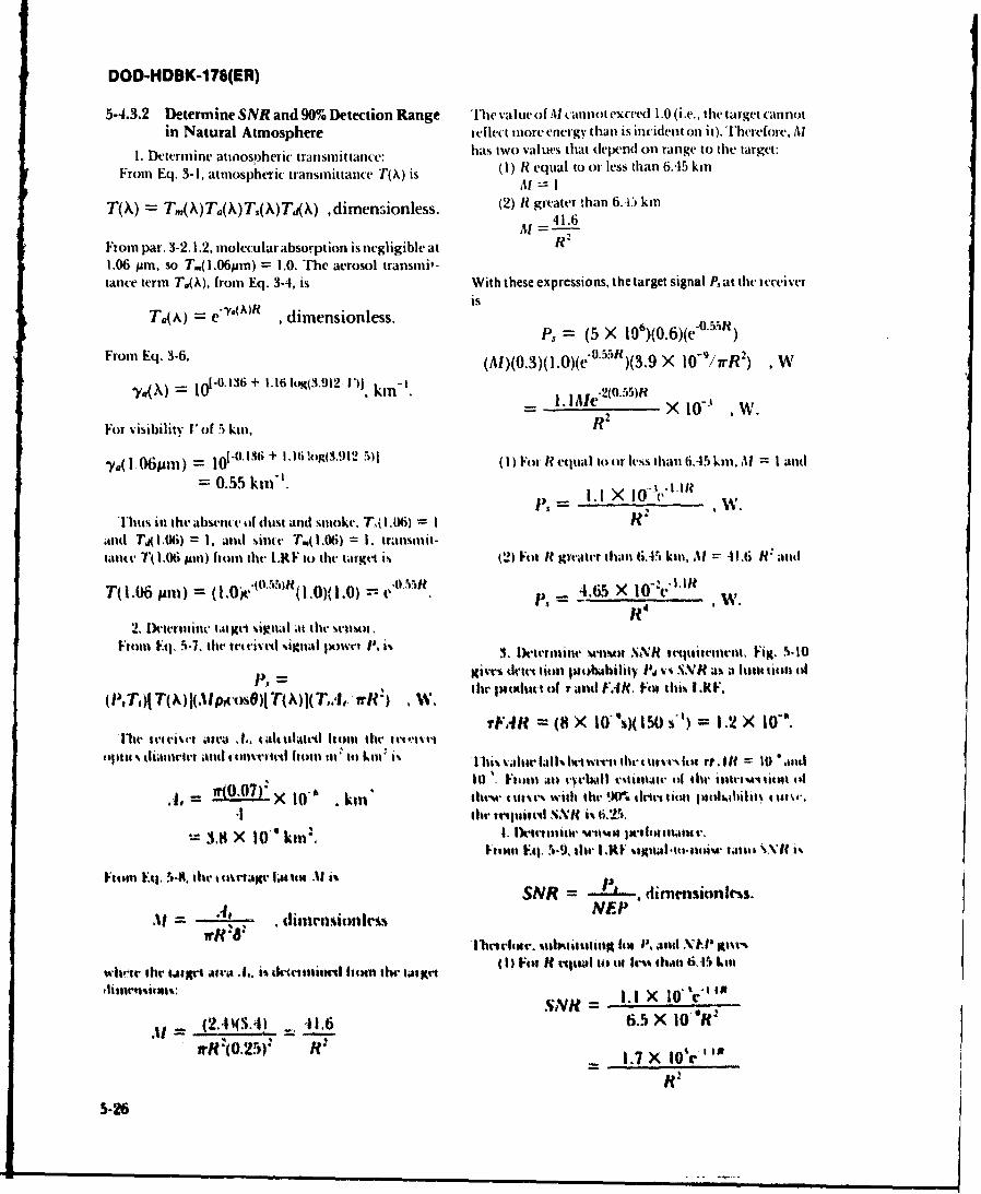
DOD-HDBK-176(ER)
5-4.3.2 Determine SNR and 90% Detection Range The value of Al cannot exceed 1.0 (i.e., the target cannotin Natural Atmosphere reflect nore energy than is incident on it). Therefore, Al
1. Determine atmospheric transmittance: has two values that depend on range to the target:
From Eq. 3-1, atmospheric transmittance T(\) is (I) R equal to or less than 6.45 kmM "- II
T(k) = T,.(X)Ta(X)T.(X)T(X) ,dimendionless. (2) R greater than 6. km
M 41.6
From par. 3-2.1.2, molecular absorption is negligible at R1.06 pr, so T.(l.06pm) = 1.0. The aerosol transmi,-tance term Ta(X), from Eq. 3.4, is With these expressions, the target signal Pat the ieceiver
'. ) isT(A) = e dimensionless. = (5 X 10⁶)(0.6)(eO.5)
From Eq. 3-6. (AI)(0.3)(I.0)(e'O-'*')(3.9 X 10-/rR2) , W
136= 0l'° + 1.16lo(3.912 "', kid'. 2 (055 )R= .Me "2 ' 5 2 10-1 W.
For visibility 'of 5 kin, R
-ya( i W6pmn) 10-0. 116 + I. 1 !og(3,912 5)I (I) For R etqual to tr less than 6.45 ki. ll = I and= 0.55 k t '. p = I.I X 10 1 , IR
Thus in lite absent t of dust and sumoke, T,(1.06) = I R'and TjO.06) = I, and since T.,.06) = I. transmit-taNlte T 1.06 pl) front the LRF to the target is (2) Fot H greater than 6.-45 kin, M -11.6 Rf and
T(I.06 Am) = (1 0 )e'° '"R(1.0)( 1.0) -- " ,.65 X 1 R "' W.
2, lktetintc larg signal at the srnsoFrntn Ft 5.7. ite ttr ivtd signail lowri '1 3. Determine wtimtt SNR tFig. S.10
p, = gives dlret tim ptoabdiliy At v .VR as a luilrtion of
(PTn)j T(M)l(Ml t)sO)j T(j(T,.A, nR) .W. lhe Ilw.tlt o( r and FIR, Felt this I.KF.
vFAR (8 X lO'~)(1SO st) = 1.2 X l0 °'.
whe rteeisto atea .4 , talhulated liton the t t'rF = X10
opt5 ttiamllret a.d t olives led holn tit .t) km i' 1hin Vahw fall. Itwtvil ifhe ntltvt It" ft. = 0 %lnd
10 1. From an rwlsrll svliralt I lhe ilke se rllitit 14
4,, = O0 X 10" . km thwm rI ttrs with the %V% uletvs till ptjwhilal ti4v.•1 silh' lrstiretl XN is i.2..,
ltrtE ~,the ItI1i(d . kP .:6 a.tt-tirtto\U1.38 X 10 "' kin:,I hll~l 'IxIv¢l!mvFloom V.41 , N-9, fill I.RF %Sgitl lItlloli-A" false$ VVX'f i%
From in Eti , 9-i . h t o riag r fi tet 11 i s =SNR . dimensionless.M = 4, - dimnsiolessNEP
Iv~a 'Ilictrhta. %libealilt m h to. alul NH*l Itm-%
wilet" the t ralt wia .,. i% d"i Itttittt I l l ive t t (I) Fiji R w l lit tit h" l Os han 6.15 Los
SNH = I.I X 10' V
.4 = )4 ) 41.6 6.5 X 10 R"Wr "I .2 ) R :
R1.7!X)-O1.7X61
5-26
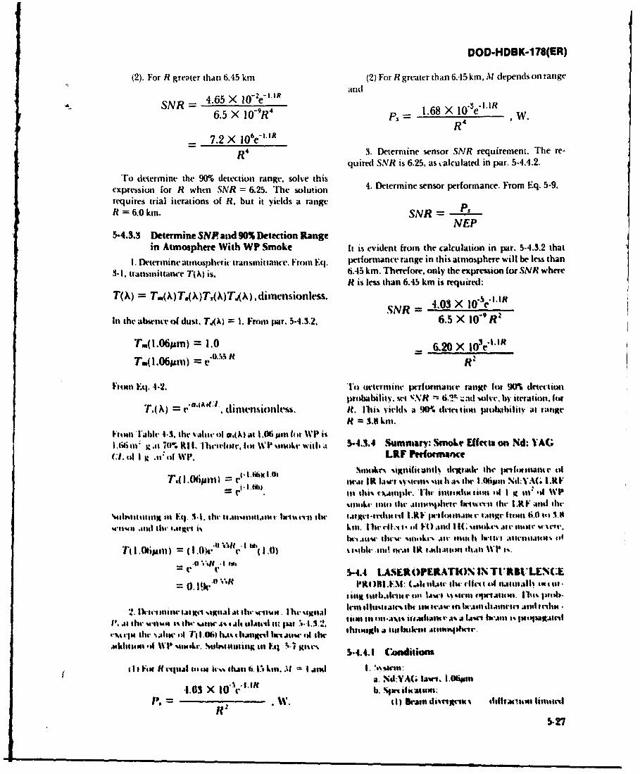
DOD-HDBK-178(ER)
(2). For R greater thani 6.45 kmn (2) For R greater than 6.45 km, Al depends on range
SNR -4.65 X 4 'etRan-3LRF6.5 X IIY9R4 1.68 X 10 e W.
- 7.2)X 1 0 6e- .1R
R 4 3. Determine sensor SNR requirement. The re-quired SNR is 6.25, as calculated in par. 5.4.4.2.
To deiermine the 90% detection range, solve this 4 eemn esrpromne rmE.59expression for R when SNR = 6.25. The solution4.Dtriesno romac.FmIq.59requires trial iterations of R, but it yields a rangeR = 6.0 kil. SNVR P,
NEP5-4.3.3 Determine SNP alid 90% Detection Range
in Atmosphere With WP Smoke It is evident from the calculation in par. 5-4.3.2 that
1. Determine atinospherit transinittaiice. Fromt Eq. performance range in this atnmosphere will be less than
3-I1. transmittance T(A~) is. 6.45 kmn. Therefore. only the exprcision for SNR whereRt is less thtan 6.45 kmn is required:
TOO) = T.X )T4QT).(A) , di inension less. SR 40 0- "I*I
tthe absencevof dust. T.9~ I . Fromt pAr. 5-.32 6NR 4OX 109 '
T(.6jim) =1.0 6 .20 X 10 3 eI.IR
T..6sit) = e*_%HR
I' ~ ~ ~ ~ ~ lutwminE,--.T twIrlln jVTrfrmalwe range for 900% detecltionprobAability.w VSe m~N 6.1Th ;:id at i it eratiot. lot
T'(A)= C'(AlO, thIt-1sionem.ft. 1161 vied% a 9(K driettioll juohitbtlitV at rangettft =3.8 ll.
l'ouaT able -1.3. the v~aloracl.IA) at 1.06 Mptt 14 r %VPi%1.66 ill K.11 70%. Kit, I'lltrtsi4r, fill %VP %ik Wit 4 5-4.3.4 Summary: Smoke Effftts on Nd: VAG;
I-tl o I t i~t~e n~ttttt dtletr tlse Irtt4tatur oT1(.Ogant I tw~u 1 I a-Ai wk~iim!, t Ii a% the 1 O6pon \'%IA(; 1.KF
its lhi% rxAliplr. 1i tltth " uIsaoll i I V tnl. .4 WVP%olok ifnt the Atmos40%ae hetwrvil the LKFa ant he
%1abiitttl ill V4,. 1. 111-t briutntjmtt swt~tirh tAigotsnlietri LXV Isetlotmttur tattgr Itesti 6,0 totA
Mw11ss n alu 1- a.41tel i% kll, Uhr dIL-4 t'. M( V.4ttd I IC %114Attar Ate flastt ss
beIt tc er flt s1ll'1r Allt11e Itti ho-1. 10tttsIt~tt ~MAK 106 0I 04-'0' Inft l 1 .0) %t1-her.41. ant! Itt-t atlttMah~Al %VP 1%.
Jr* .V, !6.54.4 1LSLROPERATh)N IN \TI RBULENC:E
0.l 'U 1S I'KON1I: (.All 1161Ct 1114 ClIte I tolf t.ualh1 o tt m-
titagt 1411ht~.414V41 IAut kic %rie InKwvA64141 114% plih.
2.M ithtsiorimttoa~e %tagnAI a thr uttt Illh-eigjnal lentl u11ll"r I, its. IAr in ht-Aast thAati-t AjIa ta~altk
MAI ltive M-otun l.[ Uc,,sW 4% ,AI4iIu tau 4 1"t 1. 13.2, tt tjin utllA%$% itijult r t as latet IWAMt isIga'~ tl41%411" the N alw 14 1' r1.ob) h.. 1,11" to"s~ k.As.o 14 th thsuagh a tuvlsaleri tn .er
ashliflos .if WI' 'olAtw . %umillititig ats FAI. S-7 gasr% S-4.4.1 ut
1iIF411 It IlJ ialotli lund 6.I. a. II.% ANa. N.I:YA( lI". 1.06*n
4.03 X t0 r b%Prifallti:r
5- 27
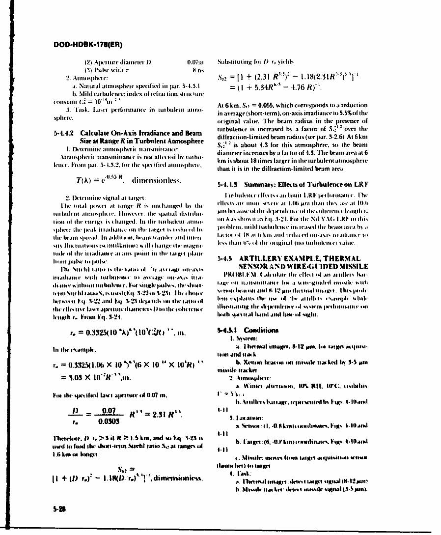
DOD-HDBK-178(ER)
(2) Aperture ditaintter 1) 0.07eti Substituting fol I) ?-, yit-lds(3) Pulse wit~i 811 li
2. Atmosphere: S,2 P ~ + (2.31 R*") 2 - 1.18(2.31R") '-,I. Natural atmosphere six-cifirdl en par, 5-4.3.1 (1 + 5.3:R"~ - 4.76 R)'b. Mild t urbultenc: indeIX Of refractlion Strt IUI lre
constant C. = 10111 At 6 km. So, = 0.055. which corresponds to a reduction3. Task. User [xrforinance ill turulen kt atllil) Ii average (short-term). on-axis irradiance to 5.5% of the
Sphere, original value. The beam radius in the presence of
turbulence is increased by a factor of S,-,' over the5-4.4.2 Calculate On-Axis Irradiance and Beam dfrcinlmt- xa ais(epr -. ) t6k
Seetinatianges ine urbttlcntn tmosph&2e's ' is about 4.3 for this atmosphere, so the beam
I. flctercnineansiniptanic Vinit anlettdb ti diameter icreases by a factor of 4.3. The beam area at 6
Itm. Finto eic tlan - 13,.li t e sis ot alttivol%pht .,h kmn isabout 18 times larger in the turbulent attnospheeelentc. -ron pee - I3 ~lenthespe ifed ttcospuc. than it is in) the diffraction-limited beam area.
= e itmnin lss. 5-4.4.3 Summary: Effects of Turbulence on LRY
2. Dikt mniet -signal at taigtc: [tehueH lcts.nliit I RFjs etcln * it.Flit- ccta ecloel att e angr k um tent tiel h% tkt rir. lt Il te111t. %ue t at I Ati JAM 11l.11 tIWer c t lt0.41
til iltlt al-1tepit Ir. I c. tdw spatial (11%te khtl. plnut ti iccw l lit e tltctck t v oil thet fiellt-1t- e ltenil 1.
I tilti III the reeelisi i.thauxt-& In lhet tultikitltnti aulli on A.I.es siisu E(1Fc.3'i21. Fell til t-: &A( I.R l .KI e%phc t. thel jIt-tL it tadialit c till the, tattgrc is. e dtiul . 1110MV ehlr 1t1114n itl t hkikllt 4- it JVk l lil~t'e Ik';Ml JgIV 11% k
cit lit-ecet %irai. Ill addcljiti . lit.lllt sxaecnht, .end ient'c. Lot till Ill Is K t 6b Late .11dt itcl t it I'sti..eilt c3 .e Ie . to
%mt Ilte Iteacitg1s INA inc ilLitiee Us Ill 4~ c~ till 1na1.1k . IV.,s 11t.ci It". ill ki l t giet.0 lit till e i lclt-ni .) iCtalltc
lttle-r oil Ihr illttat at amietl In fill- I'lit 11,11t !14. ARTIL..ERV EXAMtPLE, I&IERNIALhr ttl e ait um,stettotliiesic et's SENSOR AND) WIREG(dIDE MtNNILEs e U h r t t i 1. 4l t 1 lit- t n ta i l il l iv . % v o l u t l P I ( ) I I. ( .1lt ot l air tl eIh r i l a c a t li -u l .ec .
t ti t h a t . i~th ist b l tt 4' I e ~ts % X H tdl . 4 1 4 M A 1 .1p fillen c . se c e c~ n le g .1 w tc -g me t hlrd 111m is l %t l l
nI no 1%11rhi taliio S. I-. ttst-c t ..g. 1.22 tit A.23). I tr *hot.r V Sti411 W.04t ol.1esil . p2cill titet eetal icl.1grI, I h1%ita
htetgwi't1. El. A2V Atl V41. -1 dri-nd tll c thll 1c1tst i It-Mi V11,4.1111 taMee 1 a till-t ttieitAl ill '14'.1il9eA1111V 111
filt- e-1lt~ Ititv A - Alw mis'ttt lt. 1 1itt 1) le itt1-1 t ritt v 0140141411119~ 1114 l tlt-IM V 141 sssc - 1ee 11111t4 1tV eti
IrXbr.. Visine Vq 3-N4. looth s.ti; 1.1 hatt alud line, eu %4.*hl.
T= 0.332!r(I0 aJ-&(I0,cRD ". in. 5-.& Condiion
Its thte t-ktil~pi. 'I imal in 1.1- 1~2 prnt. list tatflAt JItitmi-
V .= 03(1.0b X 10 "), (6 >X 10" X 10,H) h tanbato t nilrIa Ab -mnsior Ittkr
1.03 X 10~I 'XR".' cmehe
Visit II %julif lal a. alliter eel 0.07 an. k,. I ah. Aitllrut IirtsAltv. trlrpn-stni t li 1 -IDatil
1) - 0.07 R, .31,C 1.".to 0.0303 ~.Rn~ewlejcsst -0a~
1hqvriuuqc. 1) t. > 3 i H 1.5 km. and w F4 11-23 tt lo,1 Fajtt f. 411 kin tantlitictI. Fix%. 10 l~srcsev.'.l 14 fat llt sbW N311 -#"n %4"dl taltVn.Sl- at san" 4
- . at"h Io faut,
~I+ (1).. 180),1 ree)"'. dimm sank s. 4. ibttu ntdte *'1sva Rl~ab. JG~san us"21. ikiri Met's IWl sal 111 1 smn!.
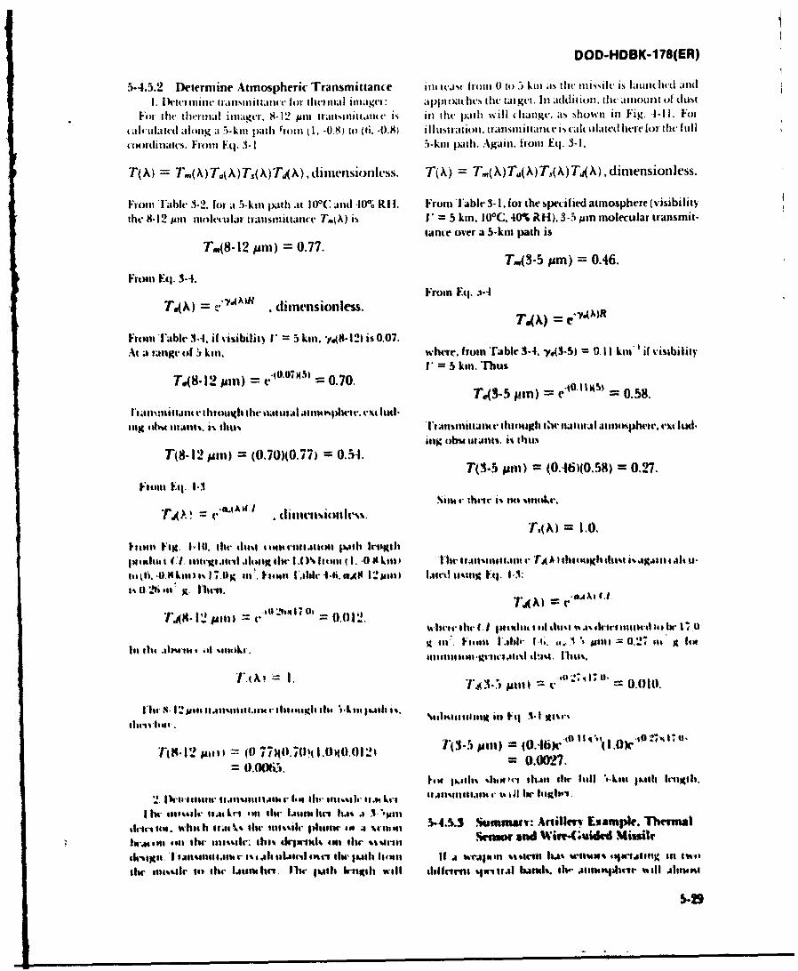
DOD-HDBK-178(ER)
5-4.5.2 Determine Atmospheric Transmittance mliis i i 10W( to 5 kini as the misiih Is latinlict aIdndI. 1)ciei mint. luarliit uit for ilici mill illndgei: *J)IIOM ilt tiliigt. li.itt In il it' 11 iuio0t O (It4 dSt
I-i tilt- teriil iinmige. 8-1 2 pin triisnlnt ut is inl ht pithi will (hangc, it-, shownt in Fig. -- 11. F01
ult t4 lated iilong i ")5-kil path rf 01m (1, -0.8 t4) (6. -0.8) iii uslition. tiiilsinlit tuno.t. i~ cal talited he'for the [fillcolmariiiwes. I-roin Fq. 3-1 5-kuut path A.gauin, from Eq. 3-1.
T(A) = '()uAT()jA infsols. T(A) = T.(\) T.(,\)T(X) TA) , dimension less.
I-rouiT-l'alt .3-2. for it 5-kin path at 1 0C and -10"' Rif, FrotnViable 3-I, for the specif ied atmosphere (visibilitythe 8.12 pun iolctilat trausmittauc T~ok) is V' = 5 kmn. 100C. 40% RH), 3-5 pin molecular transmit-
tance over a 5-kmn path isT,(8-12 pin) = 0.77.
T.n(3-5 pum) = 0.46.Froam Eq. 3-4.
pi\ = * 71') dimensionless. From Eq. 1-4 ~A
From i~able 3-1. if visibiliiw V = 5 kiw. 1.8 l2) is 0,07.At a range of kilt, where, from 'rable 3-4. -y*43-5) = 0. 11 kin'if visibility
TO(-12 mam) = evj0.7X5) = 0.70.V=5ki.Tu t-xsT.(3-5 tum) = e 0.58.
liiiiit.11itiit14' iIlli lli I Ile kuliiatsI Ali"4pKAW1t-.r t l-Iig ibd kiiJ11%. 8% 11111% I#%jimlitau4 through ,twtutuail Altmospherte. exclud-
ing tab% Islants. it Iliti%T(8- 12pin) = (0-70)(0.77) = 0.54.
T(3-5 jum) =(0-46)(0.58) = 0.927.
Fttitt Fi L* Alit
p11)41wta I C1. loit M.11i il 614Kii lim- 1.0% Iteml 1. I. 0 9 kll) Ili writ'insiueant r' TAA I thioughI 110M~ i% .4K,11 it 11d-uits (h.41 k.ll). 1% 1 7,0rn 11I'sooe Ltae4-i.itAlt 1,2u014t) 1,114.0 waingr Fq. 1,3:
Ti1hcur #Atli =I jvt4Ii =a 0.012, awjtokirs1niaitd r 17 0
t u~.1 tilt li' illiv il- Fiiuu illl 1ti .1111, 1~ .1b. tti In Iq pill 1 0 7 Itfi
7,40*) wll 0010
it ll111t ll % -1 It w ..
Tilt? ljtil i 1 0 7741).0thi1.0J0.0121 r(3-5~ ;til) =0~ pr, IO16kw0 s
lfop ,)l I lilth. dr ul iiH. 114ll 1.1,114 10.11 lhligil.
I~ ~ ~ ~ ~ ~ ~ ~ ~ ~~~~1I11111 Ci it,~il Of.1 Lii 'ct 111iwhotluol33.5 -AIer smp.T rnai r l -wi 11)0I tiai'. 4iii illI dlii .%ii IV koiolt
Ieigi lti%tli 1.ii tit-1 1',lill .1111 It"4 114* aul 3.wt *,palsj't~it~tI.% IVu)~~itKltIO
1111C itumol 4 0jI ilu- Ijuans Iwo 11W il kilitilt will tililli '4 Itil bA"Vds. eh- -linsitrl"t will jl4111"1s
5-29
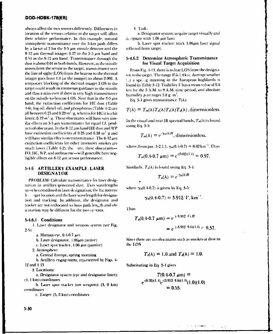
DOD-HDBK-178(ER)
always affect the two senlsors differently. Differences in 4. Task:location of the sensors relative to the taigct will affect a. D~esignator system: acquire target visually andltheir relative perforinance. In this examnple, natural uicsigfate with 1.06 pinl laseratmnospheric transmnittance oeth5-kin path differs b. Laser spot tracker: track l.O6pmn laser signalby a factor of 2 for the 3-5 pmr mnissile detector and the reflected fromn target.8-12 puin thermnal irnager: 0.27 in the 3-5 Ain hand and0.54 in the 8-12 pmn band. Transmnittance through thle 5-4.6.2 Determine Atmospheric Transmittancedust isabout 0.01 in bo0th bands. However, as the( miiissile for Visual Target Acquisitionmnoves fromi the sensor to the target, transil,ittance over Fromn Fig. 4-13, there is a clear LOS froml the designa-the line of sight (LOS) fromn the beacon to the thermal tor to the target. The range R? is 1.4 kinm. Average weatheriniager goes fromn 1.0 (at the imiager) to about 0.003. A rasp>gmonginteErpanhhldsstemiporary blocking of the thermnal imiager LOS to the found inThble 3-12. Visibility I'lhas a mnean value of 9.6target could result in erroneous guidance to thle mnissile kml for the 3 A.M. to 9 A.M. time period, andl absoluteand thus a mniss even if there is very high transmnittance humidity p av mages 5.8 g "in'.onl the mnissile-to-beacon LOS. Note that in the 3-5 pmi Eq. 3-1 gives transinittance T(X):band, thle extinction coefficients for HE dust (Table-1-6), fog oil, diesel oilI, aitd 2phosphorus (Table ,l-2) are 7'X XT,,(\) T(X) T X') , dimnension less.allI between 0.25 and 0.29 in , g, whereas for HC it isa bitlower, 0. 19 in12. g. Trhese obscurants willI have very simi- In the visuial and near IR spectral bands, T, (A) is foundilar effects onl 3-5 pinl transmnittance for equal CLi prod- uigE.33mitts of obscurant. InI the 8-12 am band HIE dust adI V uin q.33have extinction coefficients of 0.26 and 0.38 in2. g and -mXlwill have siiniflar-effects onl transmnittance. The 8-12 pinll(X e ,dimiension less.extinct ion coefficients for other inven tory smiokes are whr.fonpl-32.11,y 04.7=002k-Much lower (Table .1-2); thv. 'oie, these obscurants- whrfo pa.321, (O4 .)=002kn.huFO, HC, 'I3 , and lanthria(cene-will genierally have nieg- Tm(0.4-0.7 p )=e-(0.02)(1.4) =0.97.ligible effects on 8-12 pmi sensor performiance.
5.4.6 ARTILLERY EXAMPLF, LASER Similarly, T0(X) is found using Eq. 3-4:
DESIGN ATOR y)f
PROBLEM: Calculate ntansinittance for laser desig-nation in artillery-generated dlust. Two wav'elengths where -ya(0.44O7 ) is given by Eq. 3-5:nn~st be considered in laser dcsignation; the hunan eye
I( 1rget location and thle litser wavelength for designa- -y,(0.4-0.7) 3.912/1', kin-'.tion and tracking. In addition, the designator andtracker are not collocated so bot mpath ieril.,h and oh-sctirition mnay he dliffereint for the two Ily, Wilms. Th'lus
5-4.6.1 Conditions T.(0.4-0.7 unfl) e (-.4.912 V) R
2-)I. Laser (designiator and weapon ,ystein (see Fig. C0.912 9-6) z-- 0.57
at. Humnan eye, 0.4-0.7 pmnb. Laser diesignator, I .06pin (active) Since there ate no ob,,tarailts such i as sinokes or dust inlc. Laser spot trackeir, 1,06 pmi (passive) the LOS
2. Atmnosphere:a. Central Europe, spring mnorning T3,(A) = I .0 and Tk\) 1.I0.b. Artillevy ('tgag ?nent, repiesented by Figs. 4-
12 an~d4 13 Substituting in Eq 3-1 gives3. Lot-ations:
a. Designator systemn (eye and desigiiator laser): T(O4.O.7 Mmi)=(4, 1 kin) coordinates C'02x)1,I) -*(3.912 9.10)(.)10
1). Laser spot trackeri (onl weapon): (3, 0 kill) I.0(.)coordinates =0.55.
c. 'i'rget: (5, 0 kinl) coordinates
5-30
DOD-HDBK-1 78(ER)
5-4.6.3 Determine Atmospheric Transmittance T( 1.06) (1 .0)e( 0 .26 )( 1.4 + 2) ( 1 .0)e(0.2 )2 .0)for laser Designator C.L0027.
The 1.06-pum designator radiation propagates fromthe designator to the target and is reflected off the target. 5-4.6.4 Summary: Artillery Example, LaserThe path from the designator to the target is the same Designator(unobstructed) LOS for which visual transmittance wascalculated in par. 5-4.6.2. The 2-km path from the target In this problem, weapon system effectiveness dependsto the spot tracker contains munitiot -generated dust. on performance in two spectral bands (eye and laser)Transmittance is calculated using Eq. 3-1 (see par. 5- over two atmospheric paths. The forward observer has4.6.2). T,\() and T.(;x) are calcuated for the entire path an unobscured LOS to the target. The designator laserlength (2 km + 1.4 kin); Td(X\) is calculated only over energy propagates along the unobstructed LOS to thethe obscured portion. From par. 3-2.1.2 target 3nd then is reflected through munition-generated
dust toward the tracker. Thle target can be located andTm( .06)= 1.designated by the observer, but the laser spot trackerT.(106) 1.may not be able to acquire the target because of the dust.
Thenea IRaersolextncton s clcuate usng q. Obscuration along th des ignator- target LOS would3T, he rI VaA s g iv nctE.i-6hn vlclte siit E i affect target location and designation.greate wth .A)vn 0.6 kqi- we isbltyVI Note, however, that in the visible and near IR spectral
greaer han .6 in:bands, dust (Table 4-6) has an extinction coefficient ofy(1.06) = 10*0. 136 + 1.16 log (3.912/ "1kn- about 0.3 m.,"g; it is mutch less effective as an obsc'.arant
0.26km'.(given similar concentrations) than inventory smokes,= 0.6 kmwhich have extinction coefficients of 3.66 to SM8 m2,gT.(1.06)in the visible band and 1.77 to 1.59 at near IR wave-Ta( 106) ~ (A)Iflengths (see Table 4-2).=1e0 ,26)(14 + 2)
0.41. 5-4.7 ARTILLERY EXAMPLE,
['ranlsillnuItat,ce T.4A) through the (lust is determtined MLIEE AESSEfrom Eq. 4-3 PROBLEM: (ailculatt' the effect !Af dust ol dtown-
ward-looking. paissive minw teitninal guidance. ThisT,4 A) ptoblemn illustrates tile negligible effeti f duit of)
Froein'rable 4-6. 5-4.7.1 Conditions
041.06) =0.26. 1. Systeel. \Itulnitiln with194 (.11*pa'Asive cilninalguidlant V
111C com etnctlatiuei path length peothit cI G. of dust 111 2. Attiosphlii. iieta et:M
tho' path isstaleti frotll thle dust totentratiotlP p (toi a.s Etittitill -gnec ds. pteett elt FigFig.4'113. On the pith between the target and lilt-la Irh besetk-ri~tl itO UUItl \Ftracker. (5, 0 kill) it) (3. 0 kin). a)ptt)ioxiately 600 in iat 1ohs4 wedl by drnw I'llivi is abome 250 en tif dus! with a -I. 10iliil
ca. S. .0! kiniceionatt-s Fig. -1
ciun iolo.05g ntit Th'is givesan titegrated dtusicotell- 4. *Task. Dt iwitward Ixnk ing ter ticeal tat grit quit1360t ionath lngth 5)reltar: ~adg ac-
C1. = (0.01 )(250) + (0.05)(350) 5... Detennine Atmosphri Tranuiance= 20Cm . 1. hTljite 7A) i6 Itivr by Fq. $4I
lisT(h) =Tg(A)T-4mT,kMT4?4k
TA 1.0(5 j~in) = v*'0-2iX = 0.0055. At 9 (A WIs, Itoce Eq. 3-3
Stilt 1. 1rd0 1 = 1.0 su16titeetiaeg ill Eq. I.1I kgises T.,(A = e
DOD-HDBK-1 78(ER)
w~here -Y( 94 I 1zl) is dependentt onl absolute hunIIi(i'P 5-4.8 OBSCURING SMOKE EXAMPLE,its shown hiTlable 3-3. W~eather- data for flte Euriopeani LASER GUIDANCEhighlanlds are giveti inl Table 3.12. Ini the whiner-, aU'I - PROBLEM1N: 1)eiernine effect of smoke onl missileatge abisolte humiiidtiI) is ab~ot 1.7 g n. Atth is humid- svstei with CO., laser. guidance anld TN' oi. thermality. Table 3-3 gives -y.( 9 1 Wd li) as5 api-~oxi1cttel 0.063 target acU k~iit ion. luis prIoblem illuIstrs litekin' . Thus unlager
effect of smoke on sensors that oper-ate inl (ifferenlt spc
Tm(94 GHz) = e"'O.063 )(0 .05 0 ) = .- tral hanids but may be lpat of flte samec weapon systeii.Natural atinosphieru' tranlsmlittanice effect.s have beenlcovered in flte pirviots ext'inp~es; thecy ate not it-tated inl
Ftoin par. 3-2.2.4, ninm t adiat ion is not atlenuiatet this exam jple.by aze.T1'lrelore,
Ta(9 G~) = .0.5-4.8.1 ConditionsT,(94 ;Hz) =1.0. . SNysteil:
The 1m11W senlsor. was p~lacedl at it posit ion where't the at. 'FIVermnal imlager, 8-12 pml. lor targt loat totl)
downwa-rd-lookinig opt ical depth 01) of (lust varies awld tr-acking
tromu grevater than 3.0 to about 1.0.Tl'l dtist coticenila- sile tracig l ~ut iaki -5Ailt nta n
tionl mlust be. detertinled in order. to (al(-tlate 94 Il si( hickli
tianIl~lnc. Fro Eq -1fi C., laser, 10.6 Ati, [fo mlissile guidanice.111 a. a.'I1'.0(.7-1.1 Apml. as altern I ate br- target locat I4 n~
01) = NtT(O.4407 MIt) adtakn
= gy 0.4 71,in)CLa. Naturtal awttosphiere ignored (or- this illusti a-
Tabl -16 gvus .40447ulll g.hel-foe. tion:; T.(A) = L'4A) = 1.1 abl i~hgive a404-. intas 01.32 fin . Iletfre . Phlosphoruts smitoke [rom n Il i.n ls ilils-
thlewe 01) valkles (ot iespIXtVd to ttst Q, ItIItRItits of ttattil iti Fig. 1..21IalWtit 3 ito 10 g Ill.. NMillillnetet Wave tiall.stniltioute I. Relative humidit% Rll =-WTAMk tlnotigh duist is tak udated troo Eq. 4-3. with i. 1.(x atiott (Ser Fig. 1-21):e.A94 Gil) C4UUto0.-00I 9. M2 (fromlabc1- Fli a aI. Taigui at (00. 75 Ilitt (ooidittate%C1i. o 10 g it of thts 1), .tSeot at 0I 10. 75 Ii) 4 uottnditws (smoke has
Too) c-OAXut blownm at loss wilsor).
v 0,01Kt0 5.4.8.2 Determine Atmospheric Transmittance=0.99. lgontgau r.(h) Itlougi mitttkv i givenl h) Fq.
1 -1-2:It th (:3. wr 100 g tt. 1ht duhst ti allslin tant tertmt A
Woutld be 'I(k) = VAU
T494 .Hz) =0.90. Vialtm (tit *.(A)at 50% RH areive~n in I able 4.2. "'li.
Ckaty. . vey ~ ~GL of phosphixuas in the patsh must berdirmined from
14tt d i l 14tt t e i t vitglt I t~ '.I io no t ti at o
5,417.3 Summary: Artillery Example, Mtillimeter Ili lowl CT. i% ll'e wtill ol lt- totltlialtoll pilWave Sysitem leoitMl pirthit 1w li .h hst ni tom11II-1(ottikI1ts Iltt e L.
MNI il t iilt-Kern et41 IU%1 is Itotadi &tt1ttiiv.,bt titm iUot this itinle. a11 W1-1I'le l tFrig. fi21 t" 101-11 (3.14st ininw %)uvin%. A Ul. of 100 g tit, ni'hutem 94 G~Is 4 11m4t1 11)4' tafgu ito wilvit LOS k
ttmnunut.t". it' 0, 9O. ht~j'" ottf lI'ablv [,2 stto%% (1 (50 :n~~)+that~~~~~~~~~~~~~ 90%~ttt # % m(&t li i ua t tt ih ts' g(1 X O .O g tw t) + (30Otn hO.Oi g , till)
Itt 11W ~ stfltI.g/'m .
DOD-HDBK-178(ER)
Fioi lale 1-2 5-4.9.1 Conditions
CQ(07-1.1) = 1.77 1. System (same as par. 5-4.8.1):2, a. Thermal imager, 8-12 Am, for target location
as(3-5) = 0.29 n/g and trackingas(8-12) = 0.38 In'g b. Missile plume tracker, 3-5 Am, for initial is-as(10.6) = 0.38 mr'g. sile tracking
c. CO 2 laser, 10.6 pMm, for missile guidanceTherefore, for the 8 -12-Mim thermal sight d. TV, 0.7-1.1 sro, as alternate for target location
and trackingT,(8-12 .It) = 38)(6.5) 2. Atmosphere:
= 0.085. a. Natural atmosphere ignoredb. Vehicular dust from motorized rifle battalion
For the 3-5 ,ur sensor in attack formation, illustrated in Fig. 4-243. Location (see Fig. 4-24):
T,(3-5 Mm) = e '29)(6.5) a. Target at (+100, 325 m) coordinates
= 0.15. b. Sensor at (-500, 325 m) coordinates.
5-4.9.2 Determine Atmospheric TransmittanceFor lit 10~ 6 tMI) laserTransmittance TAX) through vehicular dust is given
T,(10.6 Inn) = e4° 38 6 5) by Eq. 4-3:
= 0.085. Td(,)=eO4(MCI '
For the (alternate)TV sight: Values for a.) for vehicular dust are given in Table
T(0.7- 1. 1) = e(177X6.5) .1-8. The C1. of vehicular dust in the path is determined
= 1.0 X 101 . forom Fig. 4-24. For the LOS selected in this example,the Q. is indicated on Fig. 4-24 as 2.8 g in'. Transmit-
5.4.8.3 Summary: Obscuring Smoke Example, tamce will lx- calculated over the entire sensor to target
User Guidance LOS. Fron Table 4-8
This ex;mple calculated transmittanctc through WP a07- 1. 1) = 0.30 mlfgsmoke for (our dilferent spectral bands that might form aK3-5) = 0.27 imC'gpart of a Weapon system using a CO. laser (or missile a48-12) = 0.25 m, xgguidance. Transmittance through the same amount oWP smoke (6.5 g, mi varied from 1.0 X l0 "' lot theITVsight to 0085 ft the CO laser to 0.15 for the 35 tm )M Therfor, for the 8-12 pn thermnal sightsensor. The clear weak link itt tbs example is dte TVsenior if operation in WP smoke is required. The TO-12) = c --0.50.example illustrate% that in a multispectral system. oe2critical senui may not be able to we through the ob-scured atmosphere, esr though the other systems have F th" 3-. it sensoradequate sigil. T, 3-5) = CO(01 )20 8 0.47.
5-4.9 VEHICULAR DUST EXAMPLE,LASER G1 IDANCE Fi I!W 10.6 Mm welsor
PROBUEM: Effett of vehicular dust ott misile sys. T4 10.6) = c(o Z2.,) 0.50.ten with O- laswt juidaiu eandrIV or thermal i.nagtrtarget acquisition. System is the sat,.? as that na. For tlhe altrne (0.74.2) V sight5.4.8. Tht, roblein illusuates the tilti of et irulatdust on sesors in diifernt sptral batls by using the 0.43.whicular dust ttxnbat rxample rum par. 4-7.3. Naturalantuiphwic transmittance is it cak teatrd.
5-3S
DOD-HDBK-178(ER)
5.4.9.3 Summary: Vehicular Dust Example, Tro=) --' (\)R
Laser Guidance
The extinction coefficient for vehicular dust is rela- From par. 3-2.1.2, y,(0.7-1. 1) = 0.05 kmi '. Therefore,tively flat in the visible and thermal bands; it variesfrom 0.32 m2/g in the visible band to 0.25 m2/g in the T,(0.7- 1. 1) = e= 0.97.8-12 pm band. For the amount of dust in this example,the effect will be small to moderate degradation itn d. Values of"/,(Y) for the C02 laser line are givensensor performance. in Table 3-3. as a function of absolute humidity p.
Absolute humidity p is calculated from relative humid-
5-4.10 PRECIPITATION EXAMPLE, LASER ity and temperature using information in Appendix B.
GUIDANCE Eq. B-I. Note that in this equation temperature is in
PROBLEM: Effect of rain on missile system w th Kelvins (Celsius temperature + 273)and Rt isdecimal.
CO 2 laser guidance and TV or thermal imager target 1285 RH r1 g/2n1lacquisition. System is the same as that in pars. 5-.8 and P - exp 5412jgrn5-4.9. This problem illustrates the effect of rain on T (i3 T
transmittance for different spectral bands. 1285 (0.4) exp[5412 ('.L I
5-4.10.1 Conditions 283.66 gim\. 273
1. System (same as par. 5-4.8.1 and 5-4.8.2):a. Thermal imager. 8-12 jim for target lcation and
tracking Fron Table 3-3. by interplation. -ym( 10.6 Utn) = 0.097b. Missile plne tracker, 3-5 ji. for initial mis- kt -' Thetn, using Eq. 3-3
sile trackingc. CO, laser. 10.6 pim. for missile guidance T,(10.6) = e 1.0) = 0.91.d. TV, 0.7- 1.1 jin, as alternate for target hwation
and ttacking 3. Deternine tilt, precipitation transtittante ternm2. Atmosphere: T({M. From Eq. 3.-12, (or visible. near IR. anti thermal
a. Winter afternmno, light rain with rain rate sj.steinsF 2.5 min h
b. Relative humidity R11 = 90%. tenperature TI(A) = VT = 100C.
3. Task. (Alhtate atinospheric transmittance over whttt It widtsprtead rain, front Fr*i.3-ItIl:i I-Lin path.
•Ye~ yS,i.wt iheaI) =0.36rt * kmn t
5-4.10.2 lmermine Amostpheric Transmittance = 0.36 (2.5)ki '"
I. 'han mnfitane T(A) is givt'n by E . 3-I = 0.64 k 5" "
= 0.4ki"T(k) = T,,(A)T,(A)T0(MT-AX)
where in the absence of dust and smoke TAX) Td)) = T.j(0 "hPt 1.0T- 1.0. It it is raining or snowing, the aerwf | extintio = 0.53.term T.(h) is replaced by tile precipitation transmit.£a4Ke term Tp(AQ. Thrteft*,- in this cae I. I et'rnanratts.pheiu tm~nsmittntvby titl ilOWS
cakulated lor T,(A) and T#(k).T() = TA)Tr . For# the 3-5 jit 5t11.,)t
2. D)risttinhe the mtoletular trmniittanmr ten". T(3-5) = T,(3-5#m)T-(35Atan)tu1 thet ondititals spitified in par,. 5-4.10. 1. - 059)(O.64 ,
a. Frun Tlek 3.1. T,,(3-5) = 0.59,
b. Frtmu'table 3-2. T,,.12) = 0.83. = 0.31.c. Fron par. S-2. 1. E. 3-3.1m visible and nea IR
Wnuw% For the 8-12 ,n sntso
5,34
DOD-HDBK-178(ER)
T(8-12) = Tm(8-12pm)Tp(8-12pm) 5-4.10.3 Summary: Precipitation Example
= (0.83)e(0.64)(1.0) This problem illustrates the calculation of transmit-tance through precipitation for near IR and thermal
= 0.44. sensors. The tra:nsmittance through rain of visual, nearIR, and thermal bands is calculated using the same
For the CO2 laser expression for Tp(X), from Eq. 3-13 to Eq. 3-15. Thedeterminant of overall transmittance in rain is therefore
T(10.6) = T,(10.6MAm)Tp(l0.6jAm) the molecular transmittance term T,(A), so, in cold
e-(0.097)(1.0) e(0.64)(1.0) weather (low atmospheric water vapor content), ther-mal and visual transmittance through rain will not be
= 0.48. significantly different. In warm weather (high atmo-spheric water vapor content), visual transmittance will
For the TV sensor be better. To calculate the efftct of rain on sensor per-formance, one must also determine the effect of rain on
T(0.7-1.1) = T,(0.7-1.1 m)Tp(near IR) target signature and, for day sights, 12 sensors, and TV.-(0.03)1.0) .(0.64)(1.0) or ambient light level.
= 0.51.
REFERENCESI. L. P. Obert and C. J. Nash. Tie I'siottits liaed- S. RCA Elcrro-Opis Haindbook. RCA Unporation,
book, AIAA 21st Aerospai e .ient't Meeting. Reno. Lmcaster. PA, 1974.NV, 198. 4. W. Wolie and G. Zissus, Eds., The Inlrared 1I1nd.
2. J. A. Ratchs. et al., Night I i'ion1t ,aboraurv Statit book, Environmental Rt ai Institute of Mhihi-Perforormanc , hel for Thermal 1'iewig y ystem,. gati, Ann Arbor iI, 197N.ECOM-7043. 'S Artily Night Vision and Met tro.Optic% Labtatorv. Fort Belvoir. VA, 1975.
BIBLIOGRAPHYlti te'ictt ev li%'tedbe IXWW~t trtatxttXs. WIIttdti ot D. W. Ilhixmk and R, A. Suthetrlad. M, lfudrhtieg tierr eadthl I t ovetgt' ai ltr " itsV Fit ctiredathlt'aihedl t. (.otiplr t)hrty /htir brlud. I'S Accnj Atintnphrtli
e11411 tll t tlttal obsilltioi Adt baltirlldinthttl " i'sthtt- 1.3A11rtboz . WhiltV %ad Md Ratnge.-ontailintlle , ltlt aMlu the the hiblingraphim in NM. 193.(halter I anlid 4. tit (-l (. ltdi . lid ILtron 1-. Eniba. /koi.e ,earegeK_%. Bandl. t't al.. M tIt mrie'r l1,41-r.'yomnOl alited toe. ifUr Smoke- "led Oi.u watils. AR.(:3,. - U%
pw.eirr, ARS(:l.-CR.83008. li 1 Re-al Ih luiltii. Alru s -Str-% 1 toralot\, .llbtii. Ml).(hiita . II.. 19141. iM
thristutqih.- I)uc antd 1.nt it'lrn i-,ets OptuaUieAl, esh. KA.it . r- atl. Qaacieratec'i- Orit raPt11001 (if Ob-ui .Asia . 11i lisacwl 111eagmi'et .ytrr,,nx. 'nitt". $4 bdroteisso Feet rti #is (reittreIl # :.op-. ASI. M4itsil-
MMinit Rerar-itt1 Anstittilt fit Mihigan. Anti Atbor, KTAslh N,1. I'N Atitn Atititinphnit Nistm l~Air.MI, 1982. Ait, White ,Nalnsls Nliilr RIange. NM. 190.
Unlii 1). Duman. es al.. I. CtI. 2. AS.- IR*0129, fail J. M~tritw. O¢,plii of thr .Iloimuqtplrr. JohitI'S Airn Atnnlihentic inem t xi abrttiur. White \Vilet & -Nutir. New Volk. NY, 1976.SAd Nlisil Range. NM. 19W2. W, F. K. Middletint. I'.te Ooueah Me to.1 ianplherr,
FrItt, k(;vbhalth. 1) t-luptnemio tt e ztboglreg, r lri ls1nivterfitoil lsmont Pist,%. t1ontoi.(aad, 912,Mode. h Ix ie-ntr A1l4licatim. Int.. Ann .4lx.I.\1l. Sttur ,Mici. (S aM I Worldaide Ita isw jt, US Attn1980. Atinosph-it Ssicnuis ILanatoi-, Whitr %amls Mii.
fittugse. N'0. k984.
5-3
DOD-HDBK-178(ER)
W. R. Lawson, I. W. Cassidy, and J. A. Ratches, "A William WaVlk' and Ceorge Zissis, Eds.. The inlraredSearch Model", Paoc. IRIS Infrared Imaging Svn- IHandbook, Enviroi1ne1ntal Research Institute ofpo.sium, Environmental Research Institute of Mih- Michigan, Ann Arlxn, MI. 1978.igan. Ann Arbor, Nil, 1978. William I. LVolfc, Ed., lndbook of,\lilirv Infrared
J. M. Lloyd, Thermal Imaging Systems, Plenum Press, Teinology, Officecof Naval Research, Washington,New York, NY. 1975. I)C, 1965.
L. P. Ole,, J. T. W\'oodl, and C. J. Nash, l'i.lonics Combat Environment Obswuration hlandbook ()raft),Handbook of EO Srn.sor Performame, l'olume I Smoke and Aerosol WVorking Group, Joint lchni-(Natural European Environment) (U!), US Army cal Coordination Group Munition Effectiveness,
Night Vision and Electro-Opti(s Laboratory. Fort Aberdten Proving Ground, MD, 198,1.Bclvoir, VA, 1981 (THIS DOCUIMENT IS CLASSI- FIetro-Optics ihandbook, RCA orpiration, Lamcas-FlED CONFIDENTIAL). ti, P1A, 197.1.
J. A, Ratches. vt al.. Night I'isimn Laboratory Statit RCA EIr(tro-Opits Ilandbook, RCA ConnercialPerformancr Model for Thermal i'ieling sy trm. . Engineering, Harrison, NJ. 1%68.ECOM-7043. 'S Army Night Vision and Electro-Optics Laboratory. Fort Belvoir, VA, 1975.
5-36
DOD-HDBK-178(ER)
GLOSSARY
A Burn rate. T'he rate of delivery of munition fill miassinto tile atmlosphere.
Absolute humidity. [he ratio of the mass of watervapor present in air to the volume occupied by themnixture of water vapor and air.
Active system. System which uses anl illuminator (lamrp Classification. The ability to distinguish a target bysource. laser, or tnnw beam) to detect targets. Th1e general type. e.g., as a tracked vehicle instead of asignal detected by anl active systemn is the illuinina- wheeled vehlicle.tor crnergy reflected by thle target (and. or back-groild). Clutter. Objet ts in lte backgrotind scene that inter-
ftre with~ the ability ol anl obseiver to acquire anudAerosol. Colloidal suspension of solid or liquid parti- distingulish targets.
tles displersed in a gas.C.oncentratiosn path length product (CL). Tlhe quailt-
Aerosol extinction. 11wi atnospheric attenuation of tit), of .an obsti want along a line of sight, obtainedradiationi due to scratterinig and absorption by sit%. by intleglattug tile obs.uranlt t onicentration alongpientdet actosol tia tit Iv-, the ;-i length.
Atr temperature. 'llie tenttiiuret of the ail a% Inca- Contrast. ldrget tadliante inunts bat kgtound tatliantcstlit by a tit y-buill thet likWIVtu.ne tlivitl by bat kgrotind radiance.
Apparenit ontrant. lh ane-ohtLttidotat Contrast tranimttance. Fhe tatio of applarent con-Usvi 1n all aibWIt s ot othl wil-Al wstltated litoni u..t it) anher.-1 to tonltat. [hle t triam t edut tioll i%the talgO A-th' ueI t .n iiat-c1dn uwdfilian *auved 6%h', l lig t attelttl in1to the sensot lsid of%t It .1' th.1 4ititbslilleut'. % iew by lt- Atit flshele Ix-wmli tile snsor and tile
tat get.Astospherit prmsure, ground level. 11w Waitt- Ipeg
11111t A.u, ttlp)li its lit, giltid In lit- 441..luunii I.D.III alotitc itD
Atmosphst tanmsmillante. l~atkii4 II Iiviss'l piwvt OMy iiight tdire view optiks). 0tat s',ten thmait) terd1414 lubsu;'s. 4*lduiwtl' ,%, I t wtfil .W a binotkulatII ot dil ,w-iit op. Wh Inith tfll 11goil'.
1411thl tltunAigI til tuu~4ee Atisu~itii,ht~oaots an snwag. lot a di sight. the himuts iv i% themaim-ii 4I-sru leuisit tilt wme-ienth li .4 t tadia. dete. tan.11111 Oi rlit III fill the 11% anmsllhe4Ii ltl. alutI t",t',aM alltd 441nnenamgn III thr altwnojdwls 41a. Dueculon. 11%, abiliq ts diatiotgueth that Ani aitu%tietaraii%. within lilt- field III %t tv i% III tooliti) ittet. Vot
thttial sk ttet.i-at itit nw)ticb ritlws MDTAtnmpheric window. A %lrt tial badl itat is I haim.- ativtsim to NIRT &tvstiun.
ItitA hj Xould ailutntspti usianmltlahc.Dew point. [hc trnlajuiatur its whis ht 44 at as gise
pn..ur Anal Wirl V.Itfu Itnti-n (&ibwlulr litionid.Is itqp Ilu be (A £ Itt' %lo t s atio its (*cu..
Seam ridier. A iiile, 1%,. whi. h the guitlat c sy'sinn4 nii 4 %41kmLuI 1 mdnit v %ignuals iansunittesl ini1
a ralat beii thiat ctuble thr inisbilt' to sens it%loaion601 selatete tW 1thV h-al. fEttitW its 4 010s. Extincion. Ihe i-nsat l of n g) b$ matictitng t*anid thetc-by MAY itIl tiv nann. tabs Jtpton (twin radiation iriasetming nstiluan.
DOD-HDBK-1 78(ER)
F pin radiation (second gecration) oi 0.6-0.9 pinradiation (th ird generation.)
r Field of view. The po~rtion (angle) of tile object A-ecIt
that is included inl thet displayed imagery of anl Index of refraction. 11w, ratio of it speed of light it,imaging system. a vatiumi to thet speed of light of spe-cifie-d wave-
length in a 1Mdiu11.
Fog. A visible aggregate of minutc water prticlessuspendled in the atmosphere at or- near groundlevel. M
Fog oil smoke. Oil dIroplet aerosol dispc-nsedl hy vaIN). Mans extinction coefficient. A measure of the effec-ring vehicle engine diesel fuel or- stx-cally sup- tiveness of an obscurant in attenuating radiation.pliedi fog oil.
Mie scattering. Scattering that otctirs from particles
G ~with radii greater thant 1 10 thet %iie of the radia-tionl wavcelngth, and brl which Mic S altoriig the-orv Inust lie used to I litalate stattet ing elfic emv
(Geometric Optics region. Pat title hifte is kligV coot.-
plared to thle Wavelengtht ol thet %t attenedl adiationl. Minimum detectable tempeature (&IDT).Tb [hAI)?"itatitetinig efft ity is abotnit 2.0 (cii geott it oif a thetilnal dlcvn tt is the mimiuntt~ittloptic-.s ttttig, differentr e betwevin a %qmam e (or i t ;1) target anid
thle hatkgrouitd mticvssali (l atl olvrvi to jIX-
H ircke the tat gtim tltiolgl. thle thrmlal ililager. it is a(tint iiti 1 mgO' .tngtda ite iti.- M Itepiesuts theVthrshtold tesrtlict c (.apaiiity lit til tein
Howt. Naititaliv it 11ting JathN'tittwi 04 toso. Whit ItIlia% int. ile dust particls IV. alt %11144. ot ilut ial Minimum res..Ivabit cotirast (MRC). A pxiallivetetpciutat%. A Iatc- i% u-411 to tk'sc tibe alintqheftvs UMisill n inocliltg thliot u~n of 1uttARe iniit.1withi %isibilitivs 1-2 kil orl givati. t. 41AN ihs alld tht- 1-r .AW: i% lilt .tptt
riltl titast ietptced In irsohe a, tallpr of a Iti~ettHtnachlinoedhane atnoke. A p~n* t'ittic %snokt gvi spati6t litiuet1 Mlad i% pitsc'1tite .1% a Ititti tioti .14
Vrted" l t11C btfing1 .4 11W IWXiKtdulctl amWlIk spatial tsc'cpwut 14 in unkits 44 i 11111 inu ot %t I-(11Ct) it tlp'4Mitiltt til altinusolti xit ii., kiltd 1IMIdhc'sathlc*cthastc tM'UltitIX itt a ht~g#ttsc tt)it *t1tt hibltik' arwcd. Minimum remlvablt tmpimaiur dilffrm-w (AIR T.
.114 ittal lialaivirteM it-e tntafci'ltug o 44ti1l1ta4-4ItVrjgvo*o~ unoe. Soutke that h~dtawcs b)- Aabb ilititg lAtlwnja' li-thallnc. AI.iti . 4wil
jugl wite lim" the .alttspwie. lltU, r.ith nuse uttutti lixtcn~r~~.allard titeou itet1-l ttit wtvi t'ncci ilitic'i t4 h Itt iii atciosc liattit h's cl'wnths st1an~tuld hial I~w tM4ttett 0I m 7:1 aNsXw11 latin).to13t frlatite hwumc1ilttv whit h a Itiatisi tshurtst Wilit l"Oltnal tisit tatl
tlistngttsli he I~~t p tit st Iuu mi pastriii. It
1d1111 I catlogs. Illt' AllililV to disc lam inate hr isam" SMU t t% I )isA ii I r
itcai 431 a1 WIWIp. e-0g.. its thililtitisl a. U .72 itti a Modualationi t1nwer function (4111). 11W si. tv.1tv
U-110 tnk. 41mleial len11irlh % tatnI.hittike. Witi It s a twasttir Wthe spatial Ijtqti*'tt % It-%31414 Nitt1 all itt61 Mit~ V
Iag inunuie. Ali sna~i" k- tr s' usi allr trtin. It i% %4114111 ik'fitwtt A% dhe 811SXh11%4tls" 1witio tube, that vrpstIuss's cm a flswessni suira 4tiull I'mciti iiaomtsit 44 aiw poiatt spsrAclatn tatugs il a rasclutius pattrn t ut it l0*1 fil liq. untwai she devitV.ttft"'tLhtti Unfair*. Im'ia ielali air iftd atntight tu padwk an% isaug that is buightt its thr Usercuw CftIoW't&.1w Jttt 5Jht~t altettttaitl is(
eri' titan thr uiiginal Ainse. T'hey npiun I 0c).4-0.9 radit~tio w slut .abusn tj ~It* in mtsatteing 1505W
G-2
DOD-HDBK-178(ER)
Monochromatic radiation. Spectrally narrow radiation Resolvable cycles. The number of cycles which the(containing energy in a very limited wavelength average observer, using an imaging system, can
region). disc: iminate 50% of the time under the set of condi-tions being considered.
0S
Optical depth. A measure of opacity to visible radia-tion. Optical depth is the negative of the logarithm Scattering. The removal of energy from a beam ofof visual transmittance. radiation traversing a medium by reflection and
refraction.
P Scattering efficiency. "'h, ratio of the effective scatter-ing cross section of a particle to its geometric crosssetion.
iearticle size distriraution. Number density or mass
density of (aerosol) particles as a function of parti- Sky-to-ground ratio. The ratio of the radiance of thehoriton sky to the inherent radiance of the back-
Pasquill category. A ,incastut of the tat of vertical ground. Sky-to-ground ratio will depend on view-
sprtatl of an ol)M IIalit from the obsurant source. ing angle, sut or intion angle, and environmental
The atllop)lt. i. ( harateriited ata unstable (Pas- and atmospheri( conditions.
quill A it B). etral (C o)IDl. or n- Spatial frequency. The frequency (in t ycles mrad or%ti btle (Vol Ii. cyclrs 1111) (f an evenly paced bar pattern or
Pasie system, Systeit llt dtw nOt ue an illumina- %intt, 'itlal target patter. One cycle is, equivalent
tor as a %ignal source. Pasive systelms delet' energy to tWOTV lines or one line pair.
emitted by the target and batkground, or rellertedambient illuminatio. T
Phoitphorlya wmsoke. P1lteihtilit s It "lliedt'tl 11%holoi tt i rt toluntnal jSltethltumis .1i . whit. h trr.tlts Turbdewe. mr-ehankal. L.otal %atitiof in windint ,, h~gIt se1t+114ht..64 - id .ta1d. stIX' an.| iltt iitiO au-t| b %atataon% art ;illno.
nlphet trilni|-yature,
R Turbuoe. optical. 'i.w.sar ing total flutuatiotsil the inder of rital tione of the antinitlhr i au%"l
Ratian. Anilr ubinldrl b;s a ao f a 4 ittle vttiul b- Ite ;ised dilerrit i tr i tt Attilttr.
inr length to the radius o the i irrle. One raliannjualk(IN0 ffdrlx. V
Radionct. 'I1w ttal radiant flu per unit solid angleper mrii prupil arr- mthirhemanasfhum a msuam. Visibility. Ilr dhsia.tr at whith a human otbstvri
tall jilst cftet a higth clt lao (C -) larget
Rayleigh scateinig. trartrinlt an whith the paitle Atov'.r.l-. t a1niruace is ploiltutitual to thesiae is small toinpatrd to the wovrlestth of the hag1rtithw 14 the vaibilitbi..attrad radiatimo Rayleilth matirrint cfliieimhas a (0 A)" dewridence. Volume extinction toeffickent. A itwastarof ille cifet
li*ve11re of an Cm. tatan. Volumc etinc tin t r ilh-Relatie humidity. 'Il wfaiauof the actual wain v.Apu fiem "'A) is drlinrsl a,
miare .44 he air i the wawr vapt ptIa ilut thawoukl Itr taised if the air we*re aturated with kin" = I t
watet vapor.
C1.3
DOD-HDBK-1 78(ER)
w hvrcR = p~ath length. kill
dI.(Ak, r) =change in .stral raidiance, Yield factor. Ratio of mass of obscurant aerosol to
W (In1:s) mass of o~bscurant fill material. Yield factor is used
L(A. i-) = pcctral radianlc. W* (,ii2S) to account for the growth of hygrostopic aerosol= wavelength, pin. particles in the atmosphere by absorption of
atmospheric water vapor.
w
lWire-euided missile. M~iss'ile that receives guidancue
Sag.1als through a Wire coninected fromn missile to
launc her.
C,.4
DOD-HDBK-178(ER)
APPENDIX A.ATMOSPHERIC TRANSMITTANCE CALCULATION SUMMARY
ThertquIionsor~ t a bl cref erences required to determine transin it tane 'are summnarized in Ili s appendix.ThelcI l 'Is of the required (lata in theirext art'referenced by paragraphI. Tables area aso referenced if the
(dta r tabulated.
A-0 LIST OF SYMBOLS -yp.(vis, near IR) = precipitation volumie extinction
i a in e'xtincti on parameflters. coefficienlt for visible and near IR,
dliisioi 11Vss kin-
(;I, concemit al ion pathl lenigth prod- -yP,4nmlw) =prec:ipitation volume extinctiontict of olbsctranll t/11 coefficient for imw, kin-'
cal 0 = (no 'xtiilcti()1i piirillllrs, A-1 TRANSMITTANCE CALCULATION
I? = p-mh lenhugth~, kinl SUMMARYI- raiiii 1r11111 Toiiihe thiilstflhiltc T(X) ISis i( t(t of thle atuno-rrail) equjtivalnt sno~w rate, 7 sphieric mnolectular transmittance term T(),thle airno-
T i') alismnitlilcn(e, (Iiiilteisioii less spheric aerosol extinct ion terml T.( A) or precipitationlT0()=amoshcr( tansittnceon- terml Fr,(X), atd the duist transmnittatce T',() or smoke
I(A) tsiherio l trnso mia c (0t1 transmittance T.(A.In dhw absence of precipitation
dimensionless T(X) = Tm,(X) T.(X) T(X) TK X), dliflin n fileCss.TXX) =transisttance through HE1' (lust Or (A-])
v'ehiictular dust, di mension less If it is rain ling or snowing,T X ) =transittaince thr1ouigh lofted
sno0w, (lillitsiollieSs T(X) = T ..(X)Tp,(X)Ts(X)Td(X), dimensionless.7*I( A) =atmosphieric- tranisin ittan(e -onl- (A-2)
sitlerimig only muolectular ext ilic-ion, Eli I ielision le'ss If there is no smoke,
TAX) =atmlosphleric transmittance con-sidering only p~recipitat ion. T,(X) =I, dimension less.dIimiension less
T,(X) =iransinittance through smoke, If there is no duist,dI il menloli less
V= viijbility, kill Ti(X) = 1, dimension less.af( ) =obscmrant mass extinctton coeffi-
ciilt, 1112g A-1.1 MOLECULAR TRANSMITTANCEas(x) =lust mass extinction co)efficienlt Tm(Ak)
for anly Wavelength X, 111/g For visible, near I R. laser, atnd miuiw wavelengths,a,(A) =smoke mass extinction coefficientI
for any wavelength A, mi/g Tm(X) =eyi( di mens ion less7,(h) =aerosol Voltimie extinction coeffi- (A-3)
cient for imy wavelength X, kin-'-Ym(X) = molecular volumne extinction coef- where
ficient for any wavelength A, km_' R jxttlileilgtli, kmn'YP(A) = p~recipitationl volume extinction Vm,,(X) =molecular volume extinction coefficient for
coefficient for any wavelength A, tiny wavelength A, kiri'.km_'
A-i
DOD-HDBK-1 78(ER)
Referenices for mnolecular voltine extictionl coeffi- Referentcs for values of a and b arecient -y,\) are Visible (0.4-0.71mi) par. 3-2.3
Visible (0.'l-O.7pn)' par. 3-2. 1.1 Near IlR (0.7-LIll) par. 3-2.3Near IR (0.7-1.lpmr) par. 3-2.1.2 Mid IR (3-5piii) par. 3-2.3
N:A laser (l.O6pin) par. 3-2.1.2 -a k(-2~m a. 3.2.3
CO., laser (10.591 pm) par. 3-2.1.4. Table 3-3 Nd:YA(; laser (I .O6yi) par. 3-2.3mmnw (35 GHz, 94l C;H-z) par. 3-2. 1.4, Table 3-3. C:02 laser (lO.59pim) par. 3-2.3
iuv(35 (;Hz, 94 GHz) par. 3-2.3.For broadbanid therina Icalculations, Tm( X) is taibulated.References for thermal transmittanice Tm(X) are A-1.3.2 Snow*
Mvid IR (3-5pin) par. 3-2.1.3, Table 3-1Far IR (8-l2;Am) par. 3-2.1.3, Table 3-2. A-1.3.2.1 Visible, Near IR, Thcrmal, and Laser
A-1.2 AEROSOL TRANSMITTANCE Ta,(X) Wavelengths'rheaersoltraistitttic tein .(X thoug lize. Inl the visible, near IR and thermial banids, and for
The. er ouso tras m ta c te m T )t ro g a e asers. the preci pi taltio n volu mue exi iuct n coeflicientfot- siioiv y, (vis. near I R) depenlds ()I] visihi litNv:
TA(X) - ~aXIdintsionless (A-4) -yp.I'is, neart IR) =3.912'!, Kin ii1 (A-7)
weey 0 (X) =aerosol extinictioni coefficienit for anly Mlr Ii = titlt. ilwvavelength X, kill-. I iiiItkn
Referenices for aerosol Vol.111 ie xtinlct ion coefficient A-1.3.2.2 Millimeter Wavelengths
-ya(X) are 'l 1111m precilpitatioi v'olun exft tct it ozi cot'fficiewiVisible (0..l-O.7pmii) lair. 3-2.2.1 for snoxv dp(U)(epeicids onl lain equivalent snlow-Near IJR (0.7-I1. 1 pm) p~ar. 3-2.2.2 rate i... and dimlenlsionlless conistants r and d/:Mid JR (3-51ptn) par. 3-2.2.3Far JR (8-l2pii) par. 3-2.2.3 -yp,(ifltnx) = cr.' , kin- (A-8)Nd:YA(; laser (I .O6min) parl. 3-2.2.2C0 2 laser (10.59pmn) par 3-2.2.3 whereimm (35 (;i-lz. 94 I Cl,) par. 3-2.2-1.. ia inl c Li laletilt Snlow% rate. 1111 h1.
A-1.3 TRANSMITTANCE THROUGH Refvieimv lot \.ilud, ()I ( aii d *IsPRECIPITATION Tp(X\) inmv(35 GClI, 9-16(1 lz) pair. 3-2.
The precilpitatioll trllumnit 1.11ncc terml TP(X) is A-1.4 DUST TRANSMITTANCE TERM 7'd(X\)
Tp(X) = -Y()I, dimensionless (A-) Ihe (luist tranlsmlittanlce terml T~xx) is
whr yp,() = precipitation volume extinctioni coffi-, vlr XX imninls A9
cicn for anty wvavelenigth X, kiuf'. ashe d (ust mlass extinc(tionl COefficimI t for ally'
A-1.3.1 Rain %vivelenigth X. 1n12/gCf. = conlcentrationl path lenigth p~roduict of'
'rhe precipitatto olinn llexetmn ctodfictieiit '/p( A) obscuranlt, g/' infor rain depends on the raini rate rand the dimenlsionllesscoristarnts a and b: Referenices for values of a,4X) are-(
y~(X) ar' k 1 ( Naturally occurinig dlust-pX -rkn(-) (all wvavelengths) part. 3-2.5
Vehicular dust (all wvavelengths) pat. 1-5where Helicopter-lofted (lust (all wavelenigths) par. .1-5.2
r=raini rate, umm/h. Munition-genierated dlust3(all wvavelengths) par. '1 -3.1.
*1 -el ic p ter- lofted snlow is 11caletd ill pars. .1-5 an .l1-5.2.A-2
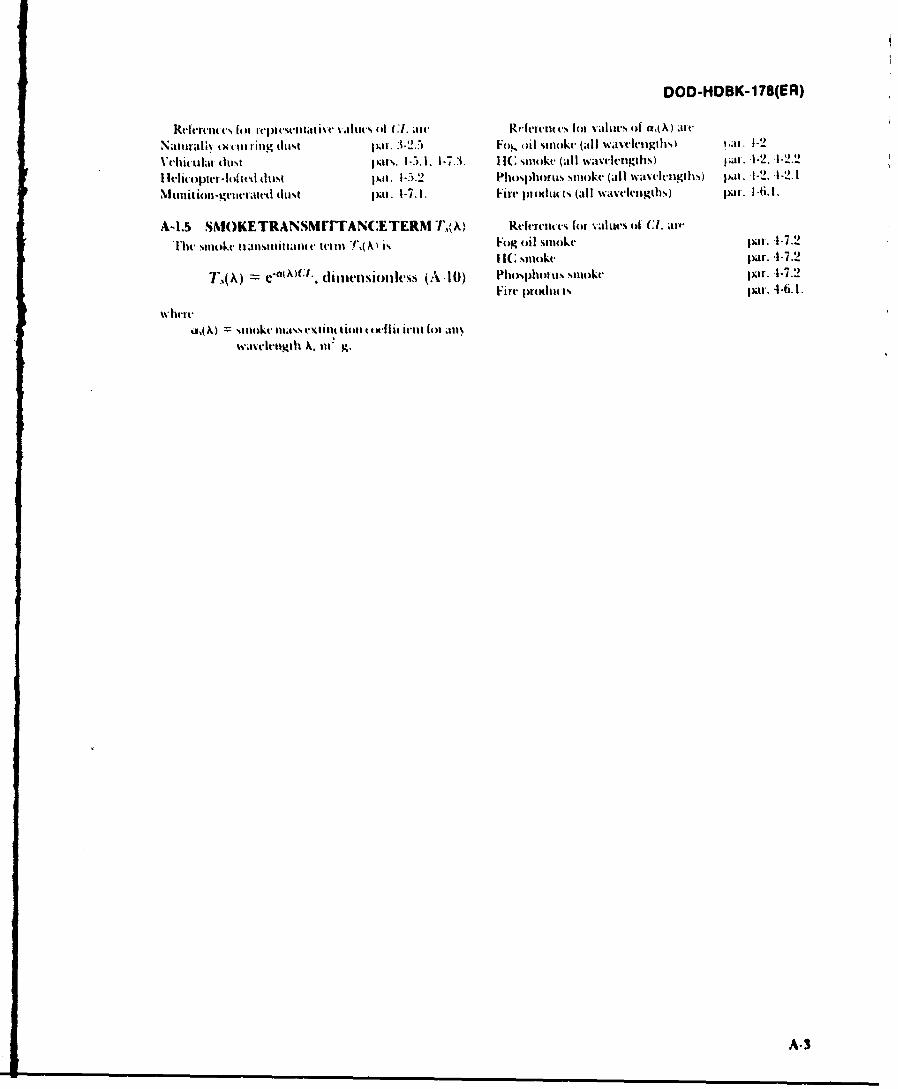
DOD-HDBK-178(ER)
keftrctiwt% ff1 )ltVl~ ~ t %,.tit% 44 (.1. al, ReItnstoC t braltics of a,(,A) at tNaturally tc (tit i ing duist pat . 3-2.5 Fo, ()I stiokc (all waveletigtiisl i,ai . 1-2
Vcikla hstpr. -7,1-73. 1 IC %ttokv (al I wavvietigilis) it.--2 -.
1I dimpte -lotted dust pat. 1-5.2 IPhosphoms Is 5t4kc (all winedciigths) pa' . 1-2. 4-2.1
Muiti oii-Igntrated (Itit pat. 1-7. 1. Firc prodlut s (all wavelethslV) pair. 1 -6. I.
A-1.5 SNIOKETRANsmrrTAN(:ETERNI T~) Relerent vs for- val urs of Cl. at-#
bit 5mttiI tiatltlittalut. c ttit 1 ( is Fog oil smoke par. -1-7.2I R; smttit pakr. -1-7.2
T.(X OeiA)Cl., dimnflikss (A-10() Phosphoitis stmotke par. -1-7.2Fire ptodtit t- par. 4-6. 1.
a, A) %mot .155 t(141 El ittit lo a141%a
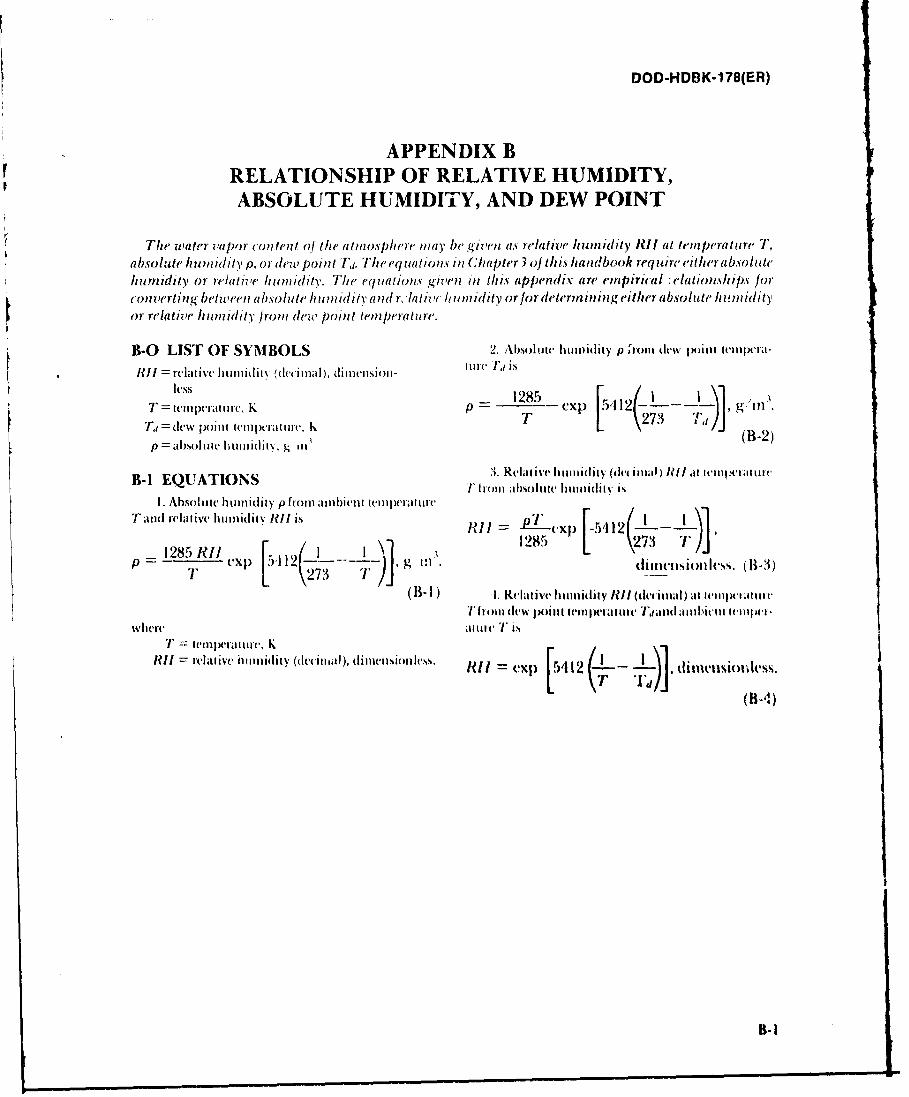
DOD-HDBK-178(ER)
APPENDIX BRELATIONSHIP OF RELATIVE HUMIDITY,ABSOLUTE HUMIDIT1Y, AND DEW POINT
The wpater vapor content of the atmosphere mnay b~e givemi as relative humi'dity RI! at temperature Ta bso ()ue htu iId It .I or dew pointt Ti,. The equta tions in C;ha pter 3 of t/is handbook req uire either absolutehumidity or re/alive humidity. The equations gwzen in thi's appendix aire emfpirical . a~tioflships for('onvertingbetween absolute hutnidity and It tilt uidity orfor determfinlinigeither absolute htuniiditor relative humildity from dew, point tempemrature.
B-0 LIST OF SYMBOLS 2. Absoltat. Il11iily p ,rolll dlew p)oint w~ilpe'i-
pM -alOille 1LillidlIlN' "cIllia) (B-2)ison
3. vlaiveI~iiiidii' (leciua ) ill dit11-c allntillt,
Taind relative hunidiiy R1ll is pi - r x 541
1285 KRIi] 1285 L\1/
(B- 1) . Relat ive hu11ifi iy lIM (dei iil 1) al ii lptI lilti
where ai tilc I' isI' ilmpe liii(, Kr
R1 ll ciiive hu midity (decimal~ ), (limionics Is. R11 e Xp L412 ( i.j.dft-(Uk%%(BA
DOD-HDBK-i 78(ER)
INDEX
A (loud cover
alim.at htnidiy. -Idata, 3-9absorpion, 2-5dt. and( tLet uial sigtatuts, 2-5aeosolm, 3- and lFsystemis, 2-1
111oletuiilal, 3-3 codwate vaior,3-3definition of, 2-12
d15issionl of, 2-3 as defeat tilchztnisin, 5-13iforillavIt1~t' ~(litIM's. 5 - definition of, 2-11
lighIt level 39 1)erfi~rtatte I. tstil s. -. -atinosplteric cxtintt 611 (0)1)s ialilitit
diiiiiion of 2-5 S defea~t nha.tistin. 5-13
ataioltetARiC stabilit. 2. 18atttl)splict( ItaI'sPittat
delittjtiioi (f, 2-8 dvivat tticIitilistttsstnatiiat Y. A- I tliso. ussiott of, 5- 1
tttltl)5l)I-ti "wind'w" 12-1 1 tbleIs. 5- 18cdet' tionl
batefed bc ttt l~telei- dflew lo oftt
a i llkerexan p l. I-0 1 ditNt.- ol
veit Waar dw.t cvamipe, 1-24) dim5 uss~iom of, 44;i
Ilvets law -tiltuitaoat 2-8 ds
blowing dust. 3.7 as Wtsed StY Iwlit opici dowiiwash. 2.-17, 1.9di-A~5OH' tmson 2- wivid 4y vebtitIrs,2". . 1-
oiltatitta 3-7 dim tussiov W., 2-1-1 .2-Ilhumai tate. 2- 18 ob)5 ula~tiIot fhil -1.9
piqsicaS prort va oil, 4.7
A itiao case vt4aou Itotofi -timo .7 3-SO0t~hrlbnt1 m tit atin data, 3- 15. 1- 17
AS 41 &AbtU Sk il itt nittil ,ryitits. 2-12 taam~tut -1
im a p . i m i t " i l le i v lu l lt I i1 1e . 1 - ( 1Amlian tm afftt liat Jhif atuIke 4. 11-I diI telIci-5
(enenal Astieiar iteritu
ubviaeagae data. 3-57. A-20 faIW "Lit Int latew"Oahet, aa, 3-12 ;Icasi- -ynsto. 5
ctk'fitititino 5-tikl:1-
DOD-HDBK-178(ER)
INDEX cont'd
fir-es index of refraction, 2-17effects on sensors, 2-17 izisolation, 3-9extinctionl coefficients, 4-1lmass kuding, 4-1l1products of, 4-11 Johnson criteriaUlrbulence ftom, 4-I11i~tOlof -
fintoog,21 table, 5-7
fo iniir I . 2 use in relating resolution to field performance, 5-6
discussion Gf, 4-6 Lextinction coeffi':ernts, 4-3lihlel
H as defeat mnechanisin, 5-13
haze discussion, 3-9
definition of. 2-12I-IF -generated dustM
artiller) example, 4-13 m11ass extintioii ((kifficientturbulence ill. 2-' (definition., 2-17
loud teloperatur , -1-8 intertol4)gi(,tl mieatstrables, 2-18(lusi and debris tromn. 4-6 Midetstm detit-gas emnissais, 4-7 des(I i pt ioI of. 3-1ltinass v~titlti(Ut cot-f inieiits, -1-7 obst uation data, 3.17, 3-'.1lphases of, .1.6 timallilitante 3-26
helit iquer downwash wcatht'l datia. 1- 13vilet Iol traustnittaI1v and LOS. -W)9 Mir!*.Aaa ilig Olit it-li Y
hi~x~ntt~~tehan diniition ol, 2-6ithwscusioa o, .- 5 m1W1it of, 2-0rxtint tiot ot-ffwients, -1.5 anillattt'l W;IVV NISW
it-lit lit tot . 4.5 thmi%4twi lI 'J. $5*'ill %pill%,. an61iitimn (lc. talh' tt.',tit~Nl ,dlitn
itgihiits will%, 2-11 deflititi 10h, ' 13
high-explioiVe ttttittitiont-pjtttutttd df tst lud t1111111111 It-sokah .dffi .)It as NR( :Pbilt-AeS it, 2-16 tithfiaaliol tif. 5-3
tejwatai.-1-8 11hiiil -t'solvdlblt titilata ate i.l R F) dillvillt vo nsujune4--7 ak-hinitgoll 44, 5-3
It'ro.ou ersl pa14. lc oo umnagdiatonas nneao41- by sirld fmt ttn, 2- 18 de-l tiau, ofl. 2-4
illumination. natural, 1-9 its mni tions %%ih it h- -Aitit',i. 2-7illustative prblm :n.:luts1wo itat wils. 5-7
(Abram-riderf. 5-32 Il'h l~l -
day tight. S. 14?NJd:AC 1.RF. 5-25laser desigiult.. 30 noisei eqtNah-n ISWI
111111W sOeu. -1eft: oll .igral-lo-stiliw mo.
awrbultr. .4-27fl)6 at det-ih. 1-12
wsile-gtiditkliswtile. 5.iL41t. Iuen
1-2
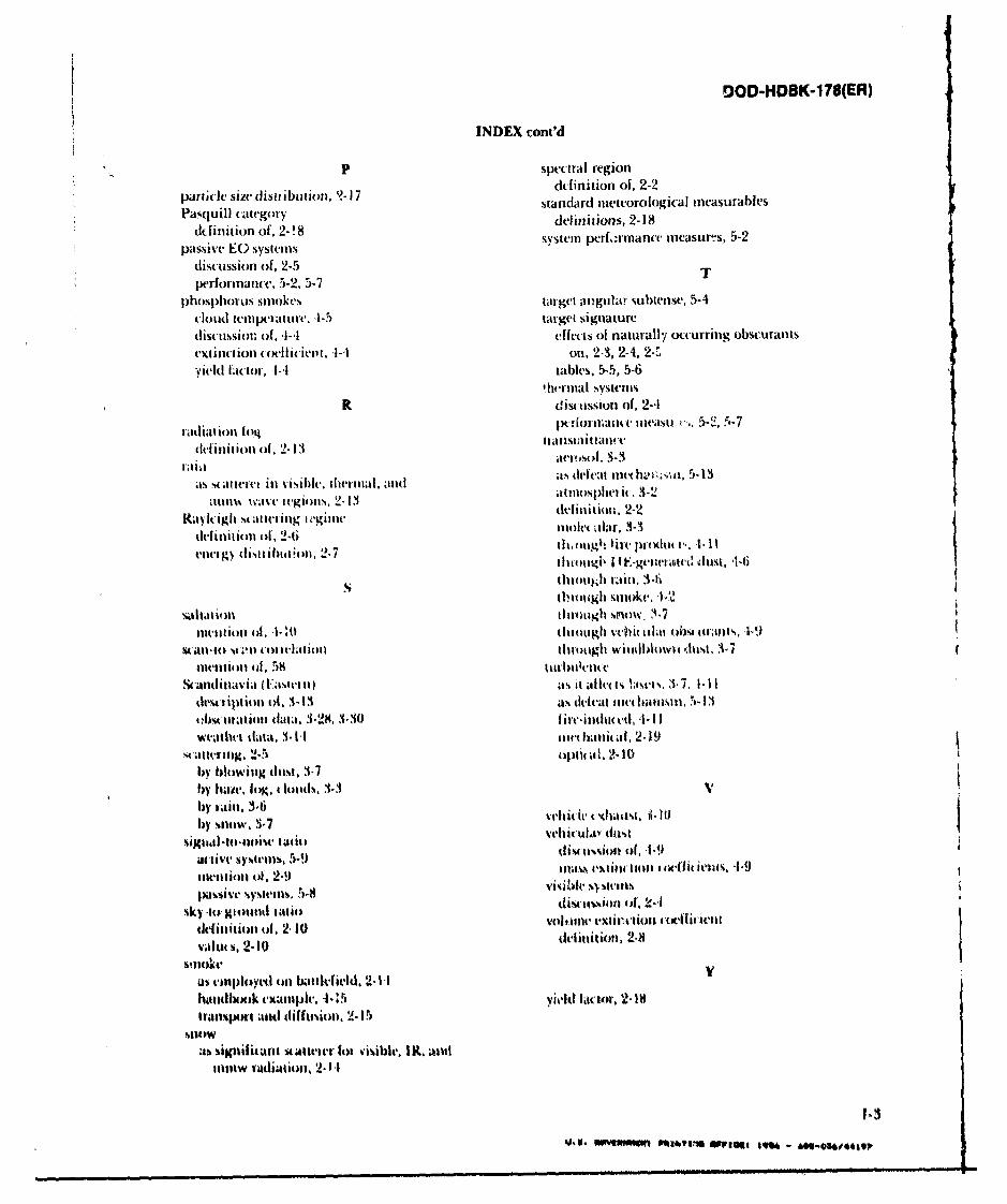
0OD-HDBK-1 78(ER)
INDEX cont'd
P spectral region
partcle j~edistabuon, J7ddinition of, 2-2pail i z c st rybv o ,'-1 standard meteorological ineasurables
ddfinition of, 2-!8 deliniuions, 2-18passve E sysemssystemn perf-rinance ineasurts, 5-2
discussion of, 2-5 Tper-formance, 5-2, 5-7
phIosph~orus smiokes~ targetma giilai subtense, 5-4cloud temlperatur..4-5 target signaturediscussion~ of, I-l effects of naturally occurring obscurantseXti1ct iOfl (oi~iill, -1-4 on, M-, 2-4, 2,s.yield Ihmcor, .1-1 tables, 5-5, 5-6
thernmal SystemTSR discussion of, 2-4
fcdag pttiornuae nleast. r., 5-2, 5-7
cdnitinti of. 2- 13 ttittlsillittanE tersc,3-3
itsmilIIVIil vsibc.Ilermlaan defeat i l '.-u 5-13c mttm wavewgijsill. 2-cmm13 m atiflospl ci c, -1
aytgmtmt c ias g w -Ii definion. 2-2
ditltion of. 2-6tioc Ilr -
Oluotigil I t.-gel-wranc( dust, 1-6
thrcnii~li rain., 3-6
tI'rot iMI Snow~k. 4.
tiiltiot) 4o, .1-10 tiltigh lii i~ obswi ans, P-9
54atl-() U.111 cont clioll tiuimuigh willdblomli dust,3-
aniai( atctit) as It .alivo ltmv'.ct 3,-7. I- 1I
dtit" ipt im i , 1.13 as defeat fiet hanlliu, w- 13t~btitat ion daita. 3-28, 3-30 1 i rcinldmeid, 'I-I Iwvmultm tata. 3-I mnr hanit at. 2. t9
mattmig 2in. 51by blowinig dutst, 3.7bV 11-11C. 10K. A lotids. 3.3by rain. 3- eIvh 'ail 1tby sniow. 1-7 elc.Vds
tittii oft, 2 llu delintiloti 2.8 t-is,+
xisnow Syvls 5-8 L tisible 1K. ant
as vinloyvd ilI battlefield, 2- 1-1c'il~oo xammple, .1-:5 v vid tilt-tor, '2- 18
tralsimrt nd ifutsioo, 2. 15
numiw vadliation, 2-l
INS1ThIJUMOHS: Insa continuing a - t to make our standIazton documents better, the DoD provides this form for use insubmitting comnments and suggestions for improvements. All users of mibtary standardization documents are invited to providesuggestions. Thia form may be detached, folded along the lines indicated, taped along the loose edge (DO NOT STAPLE). andmailed. In block 5, be as specific as possible about particular problem arem such a wording which required interprvtation, wastoo rigd, restrictive, loose, ambiguous, or wea incompatible, and give proposed wording changes which would alleviate theProblems. Enter in block 6 any remuarks not related to a specific paragraph of the document. If block 7 is filld out, anacknowledgement will be nua~ed to you within 30 days to let you know that your comments were received and are beingconsidered.
NOTE: This form may not be used to request copies of documents, nor to request waivers deviations, or clarification ofspe0cification requirements on current contracts. Comments submitted on this form do not constitute or imply authorizationto Waive any portion of the referenced documient(s) or to amend contractual requirements.
(Fold alon th line)~w
DEPAFITMENT OF THE ARMY~
FOR~~~~ ~~ ~O PMyAA Io USN SSRPL AI
VIRS? C'LASS "I NMtT NO 12062 VVAS*INGTON C) C
POSTAGE WILL. BE PAID BY THE DFP,*,R1MENT OF THlE AR1MN _______
Commander/ D irectorUS Army Laboratory CommandAtmospheric 13ciences LaboratoryATTN: SLCAL -AR-AWhite Sands Missile Range, NM 88002-5501
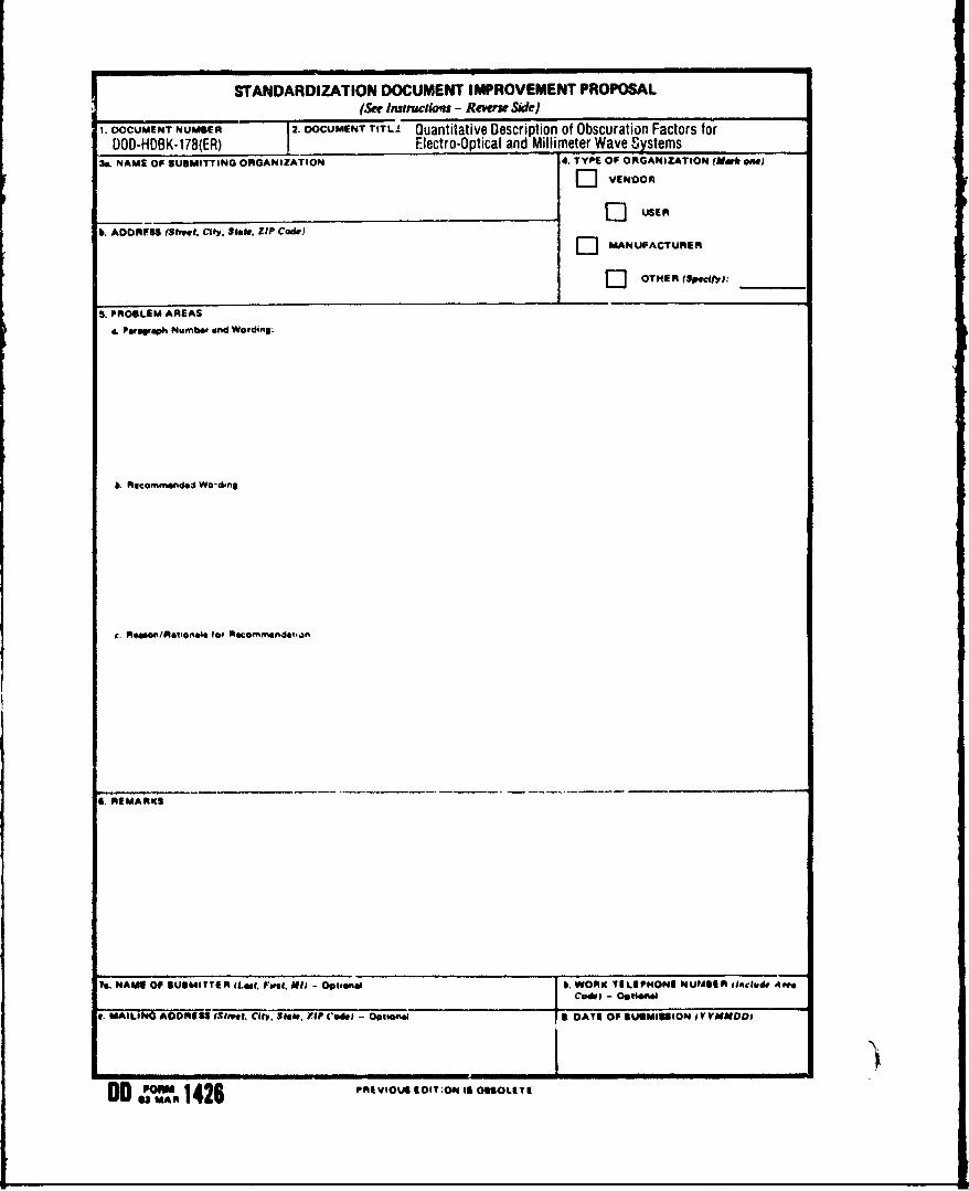
STANDARDIZATION DOCUMENT IMPROVEMENT PROPOSAL(See Inst nctio'as - Reverse SWe)
1. DOCUMENT NUMBER .DOUENT TITLA Quantitative Description of Obscuration Factors forDOD-HDBK-178(ER) Electro-Optical and Mllimter aveSystems
3a. NAME OF SUBMITTING ORGANIZATION 4. TYPE OF ORGANIZATION (Me* eowl
CVENDOREj1 USER
k. ADORFSS (Shvct. City. Sik. ZIP Code)
EJ3 MANUFACTURER
C OTHER (SMptfy3:_____
S. PROBLEM AREAS
&Pwsorah Number and Wording:
6. Recommended We-ding.
c. R4ason/Relioneis #of Rocoemmndeqan
.REMARKS
Is, NAME OF SUBMIT T* I IteI PFwu. NJ) - Optiea.i 6 . WORKC TILEP4ONIE NUMBEIR ftclude A"e
C&I - 9sw
*MAILIN41 A0ORIB Strf.et. City. liii., rip C'ode) -OplionelI DATE OP SUBMISSION IVVYMMD
00 1P0'" 426 PRE VIOUS 9 I;f IS OBSOLE TE