Embed Size (px)
Citation preview
www.quantum.com
SuperLoader 3
SuperLoader™ 3 Quick Start Guide
The Quantum® SuperLoader™ 3 is an automated storage and retrieval device consisting of a tape drive and up to two tape magazines holding up to eight cartridges each.
For more information, see the Quantum SuperLoader 3 User’s Guide (PN 81-81317) on the documentation CD provided with your autoloader.
This quick start guide uses the following conventions:
Note: Notes emphasize important information related to the main topic.
Caution: Cautions indicate potential hazards to equipment and are included to prevent damage to equipment.
WARNING: Warnings indicate potential hazards to personal safety and are included to prevent injury.
This document explains how to unpack the SuperLoader 3 and install it in a standard 19-inch rack.
Contents
Choosing a Location...............................2
Preparing for the Installation.................2
Providing Necessary Tools ..................3
Taking ESD Precautions ......................3
Preparing for Rack Mounting.............3
Unpacking the Autoloader .....................4
Checking Accessories .........................5
Rack Mounting the Autoloader..............6
Autoloader Panel Overviews ................11
SCSI Bus Requirements.........................12
General Information.........................12
Connecting SCSI, SAS, or Fibre Channel and Power Cables.................................13
SAS 1 and SAS 2 Connectors............12
Setting the SCSI ID ...............................17
Preparing the Host and Verifying the Connection ...........................................17
Windows Operating System Support...18
Autoloader Device Driver .................18
Tape Drive Device Driver...................19
After the Installation............................19
SuperLoader 3 Quick Start Guide
Choosing a Location
The autoloader is designed to fit in a standard 19-inch rack using either the long or short brackets (depending on the depth of the rack). The autoloader uses standard rack mounting hardware.
Note: It is recommended that you review this entire document prior to beginning the installation
Choose a location that meets the following criteria:
Preparing for the Installation
Before you begin the installation procedure in this section, make the following preparations as described in this section:
• Providing Necessary Tools
• Taking ESD Precautions
Criteria Description
Rack requirements Standard 19-inch rack
Room temperature 10–35° C (50–95° F)
Power source AC power voltage: 100–127 VAC; 200–240 VAC Line frequency: 50–60 HzNote: Locate the AC outlet near the autoloader. The AC power cable is the product’s main disconnect device and must be easily accessible at all times.
Weight 14.1 kg (31 lb.) unloaded 17.2 kg (38 lb.) loaded with 2 magazines, 16 cartridges
Air Quality Minimize sources of particulate contamination. Avoid areas near frequently used doors and walkways, cooling or exhaust vents, stacks of supplies that collect dust, printers, and smoke-filled rooms.Caution: Excessive dust and debris can damage tapes and tape drives.
Humidity 20–80% RH (non-condensing)
Clearance Back: Minimum of 43.2 cm (17 in.) Front: Minimum of 68.6 cm (27 in.) Sides: Minimum of 5.08 cm (2 in.)
2 Choosing a Location
SuperLoader 3
• Preparing for Rack Mounting
Providing Necessary Tools
Provide the following tools for unpacking and installing the autoloader:
• #2 Phillips screwdriver
• Level
• Antistatic wrist strap
Taking ESD Precautions Some components within the autoloader contain static-sensitive parts. To avoid damaging these parts while performing installation procedures, always observe the following precautions:
• Ensure that the work area is free from conditions that could cause electrostatic discharge (ESD).
• Discharge static electricity from your body by touching a known grounded surface, such as your computer's metal chassis.
• Keep the autoloader turned off during all installation procedures.
• Use an antistatic wrist strap.
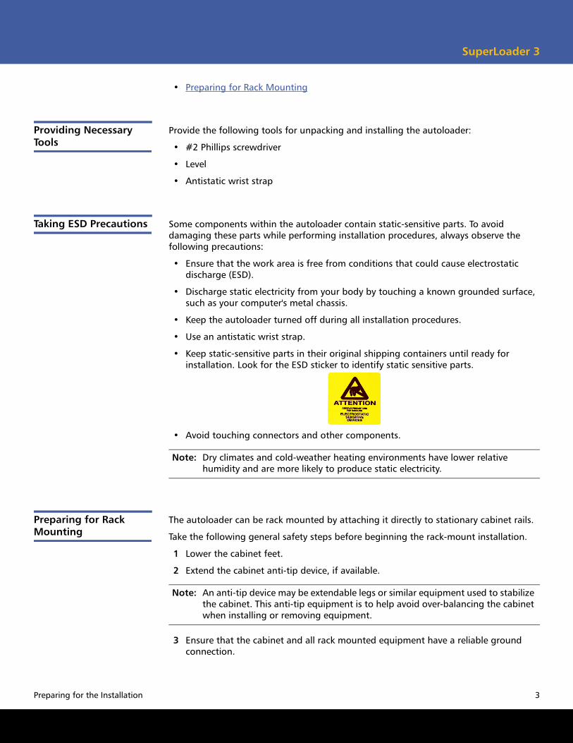
• Keep static-sensitive parts in their original shipping containers until ready for installation. Look for the ESD sticker to identify static sensitive parts.
• Avoid touching connectors and other components.
Note: Dry climates and cold-weather heating environments have lower relative humidity and are more likely to produce static electricity.
Preparing for Rack Mounting
The autoloader can be rack mounted by attaching it directly to stationary cabinet rails.
Take the following general safety steps before beginning the rack-mount installation.
1 Lower the cabinet feet.
2 Extend the cabinet anti-tip device, if available.
Note: An anti-tip device may be extendable legs or similar equipment used to stabilize the cabinet. This anti-tip equipment is to help avoid over-balancing the cabinet when installing or removing equipment.
3 Ensure that the cabinet and all rack mounted equipment have a reliable ground connection.
Preparing for the Installation 3
SuperLoader 3 Quick Start Guide
4 Verify that the total current of all rack mounted components (including the autoloader) will not exceed the current rating of the power distribution unit or outlet receptacles.
5 Secure the help of at least one other person. At least two people are required to safely install the autoloader into a rack cabinet.
WARNING: Failure to take these safety steps may result in personal injury or equipment damage.
Caution: Do not remove the top cover of the autoloader during the installation process. Removing the top cover could result in damage to the autoloader.
Unpacking the Autoloader
Before you begin, clear a desk or table so that you can unpack the autoloader.
The Quantum SuperLoader 3 Quick Start Guide has all the necessary information to unpack and inspect your autoloader correctly.
You also need to select an open 2U computer rack location near the server that will host the autoloader.
Caution: If the room in which you are working differs from the temperature in which the autoloader was shipped or stored by 15° C (30° F) or more, let the autoloader acclimate to the surrounding environment for at least 12 hours before removing it from the shipping carton.
Caution: If your unit was ordered as a one-magazine autoloader, be sure to remove the plastic shipping insert from the magazine bay before connecting or operating your autoloader. Insert either a magazine or a magazine blank into the bay. The autoloader will not function without both magazine bays equipped with either a magazine or a magazine blank.
Carefully unpack and inspect your new Quantum SuperLoader 3 by doing the following:
1 Inspect the shipping box for damage. If you notice any damage, report it to the shipping company immediately.
2 Open the shipping box and remove the accessories package. Set the accessories package aside for now.
3 Lift the autoloader and padding out of the box and place it on the work surface, top facing up. Do not set the autoloader on either end or sides.
4 Carefully remove the shipping padding from the left and right sides of the autoloader. Then remove the bag from the autoloader.
4 Unpacking the Autoloader
SuperLoader 3
5 Remove the foam insert from the magazine bay of the autoloader. Save the packing materials in case you need to move or ship the autoloader in the future.
Note: If the cover must be taken off, there are 26 screws that need to be removed.
Checking Accessories The following accessories are shipped with the Quantum SuperLoader 3:
• Quantum SuperLoader 3 Quick Start Guide
• SCSI tape drive kits
• SCSI host or server cable
• SCSI terminator (not included with Serial Attached SCSI)
• Fibre Channel tape drive kits
• Fibre Channel cable
• SAS tape drive kits
• SAS cable
• Ethernet cable
• Hardware to rack mount the autoloader (see figure 1)
• Four autoloader brackets (two long and two short to accommodate different rack depths)
• Two support brackets
• Two sets (decimal and metric) of four support bracket 10-32 x 1/4 inch button head screws (two per support bracket)
• TORX® L-Key drivers (T8 and T10)
• One magazine blank
• Power cable
• Documentation CD containing all of the documentation in Adobe® Portable Document Format (PDF)
• Bar code labels
You will also need the following parts that were shipped with your rack:
• Eight clip nuts
• Eight rack screws
Unpacking the Autoloader 5
SuperLoader 3 Quick Start Guide
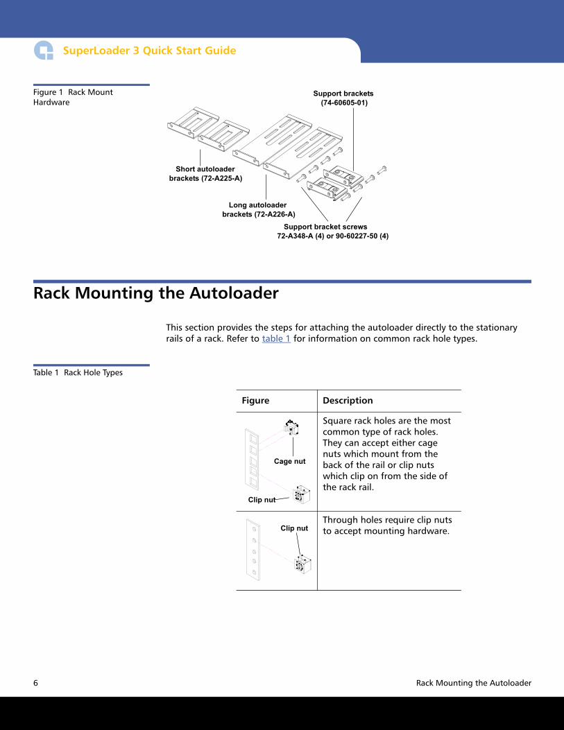
Figure 1 Rack Mount Hardware
Short autoloader brackets (72-A225-A)
Support brackets (74-60605-01)
Long autoloader brackets (72-A226-A)
Support bracket screws 72-A348-A (4) or 90-60227-50 (4)
Rack Mounting the Autoloader
This section provides the steps for attaching the autoloader directly to the stationary rails of a rack. Refer to table 1 for information on common rack hole types.
Table 1 Rack Hole Types
Figure Description
Cage nut
Clip nut
Square rack holes are the most common type of rack holes. They can accept either cage nuts which mount from the back of the rail or clip nuts which clip on from the side of the rack rail.
Clip nutThrough holes require clip nuts to accept mounting hardware.
6 Rack Mounting the Autoloader
SuperLoader 3
Note: The rails within the rack have a hole pattern that repeats throughout the rail.
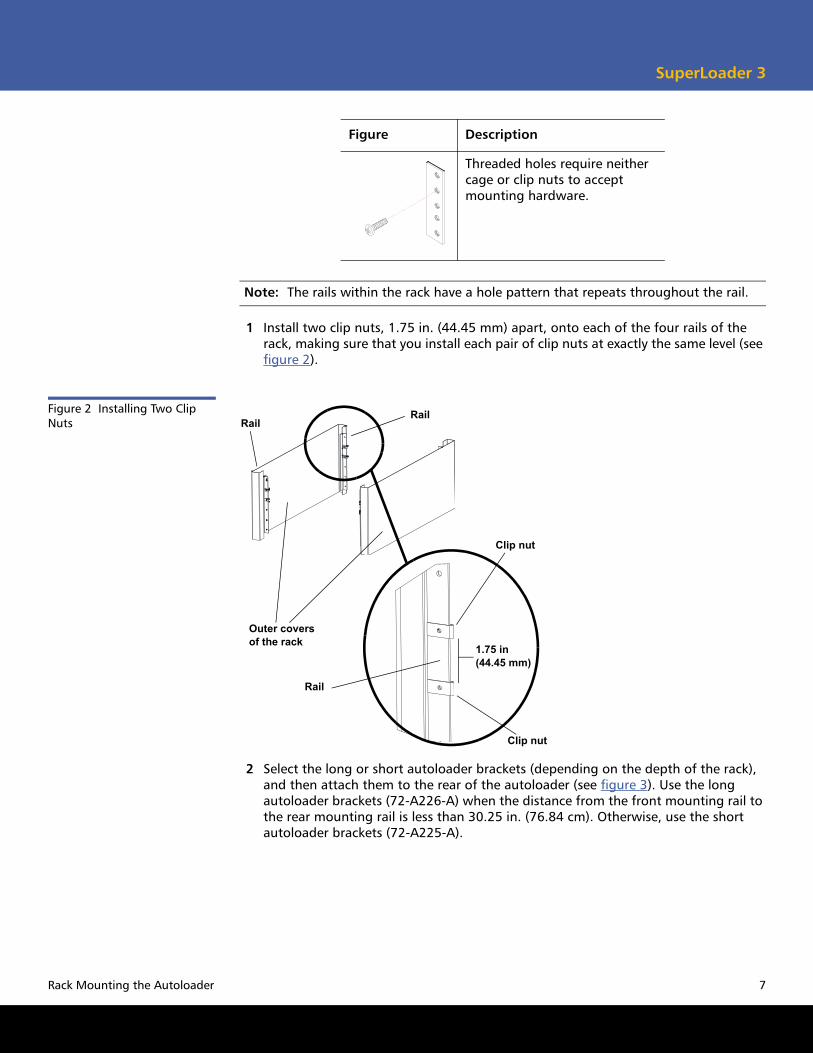
1 Install two clip nuts, 1.75 in. (44.45 mm) apart, onto each of the four rails of the rack, making sure that you install each pair of clip nuts at exactly the same level (see figure 2).
Figure 2 Installing Two Clip Nuts
Outer covers of the rack
RailRail
Rail
Clip nut
1.75 in (44.45 mm)
Clip nut
2 Select the long or short autoloader brackets (depending on the depth of the rack), and then attach them to the rear of the autoloader (see figure 3). Use the long autoloader brackets (72-A226-A) when the distance from the front mounting rail to the rear mounting rail is less than 30.25 in. (76.84 cm). Otherwise, use the short autoloader brackets (72-A225-A).
Threaded holes require neither cage or clip nuts to accept mounting hardware.
Figure Description
Rack Mounting the Autoloader 7
SuperLoader 3 Quick Start Guide
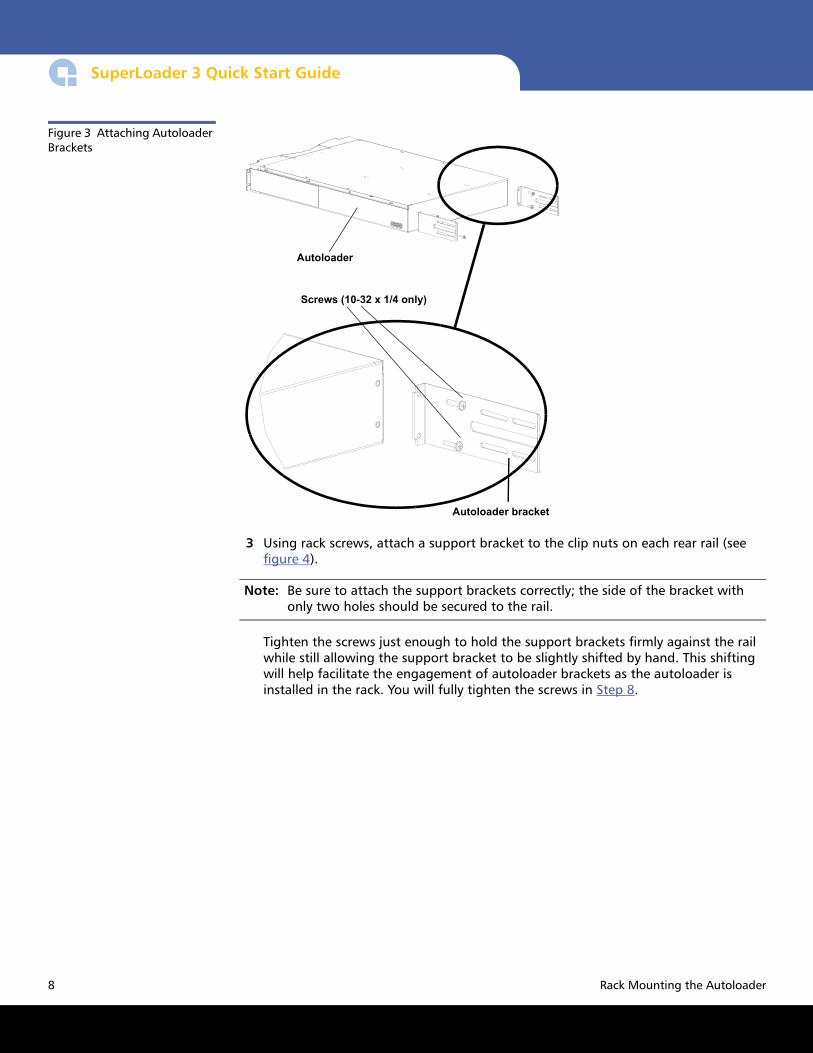
Figure 3 Attaching Autoloader Brackets
Autoloader
Autoloader bracket
Screws (10-32 x 1/4 only)
3 Using rack screws, attach a support bracket to the clip nuts on each rear rail (see figure 4).
Note: Be sure to attach the support brackets correctly; the side of the bracket with only two holes should be secured to the rail.
Tighten the screws just enough to hold the support brackets firmly against the rail while still allowing the support bracket to be slightly shifted by hand. This shifting will help facilitate the engagement of autoloader brackets as the autoloader is installed in the rack. You will fully tighten the screws in Step 8.
8 Rack Mounting the Autoloader
SuperLoader 3
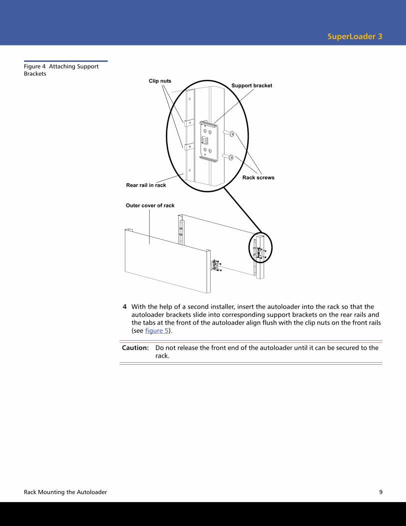
Figure 4 Attaching Support Brackets
Support bracket
Rack screws
Clip nuts
Rear rail in rack
Outer cover of rack
4 With the help of a second installer, insert the autoloader into the rack so that the autoloader brackets slide into corresponding support brackets on the rear rails and the tabs at the front of the autoloader align flush with the clip nuts on the front rails (see figure 5).
Caution: Do not release the front end of the autoloader until it can be secured to the rack.
Rack Mounting the Autoloader 9
SuperLoader 3 Quick Start Guide
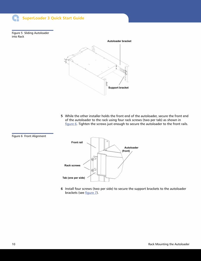
Figure 5 Sliding Autoloader into Rack
Support bracket
Autoloader bracket
5 While the other installer holds the front end of the autoloader, secure the front end of the autoloader to the rack using four rack screws (two per tab) as shown in figure 6. Tighten the screws just enough to secure the autoloader to the front rails.
Figure 6 Front Alignment
Front rail
Rack screws
Tab (one per side)
Autoloader (front)
6 Install four screws (two per side) to secure the support brackets to the autoloader brackets (see figure 7).
10 Rack Mounting the Autoloader
SuperLoader 3
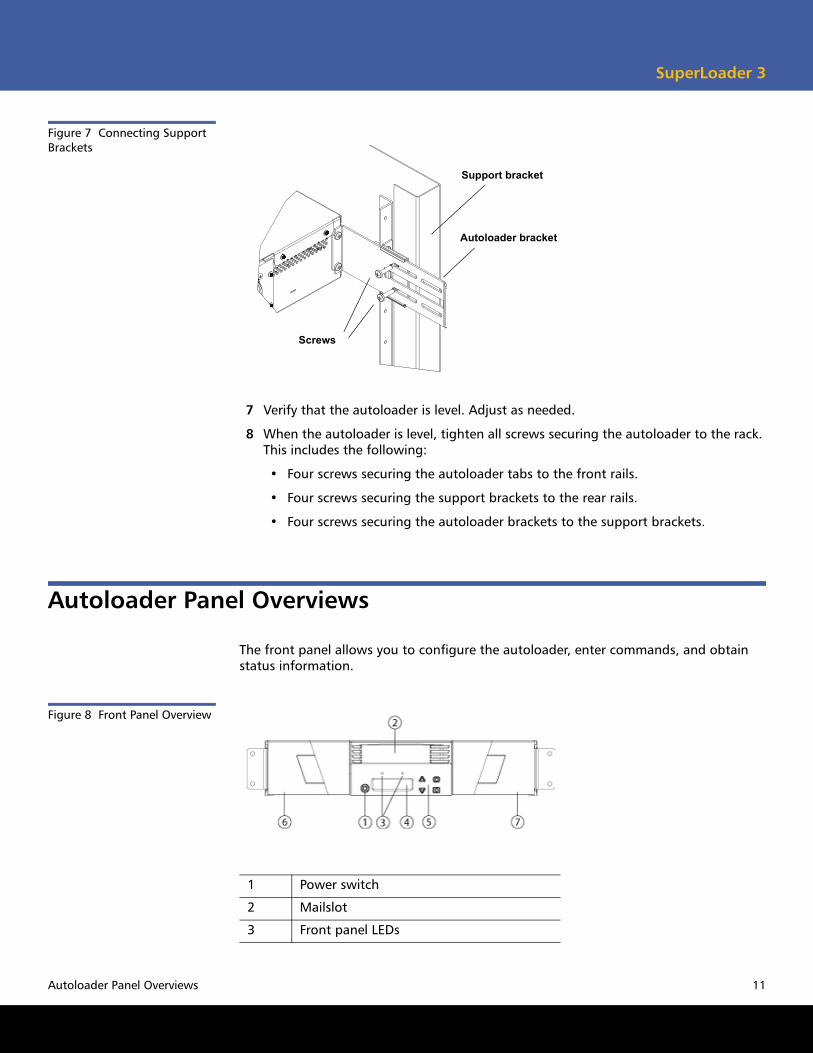
Figure 7 Connecting Support Brackets
Screws
Support bracket
Autoloader bracket
7 Verify that the autoloader is level. Adjust as needed.
8 When the autoloader is level, tighten all screws securing the autoloader to the rack. This includes the following:
• Four screws securing the autoloader tabs to the front rails.
• Four screws securing the support brackets to the rear rails.
• Four screws securing the autoloader brackets to the support brackets.
Autoloader Panel Overviews
The front panel allows you to configure the autoloader, enter commands, and obtain status information.
Figure 8 Front Panel Overview
1 Power switch
2 Mailslot
3 Front panel LEDs
Autoloader Panel Overviews 11
SuperLoader 3 Quick Start Guide
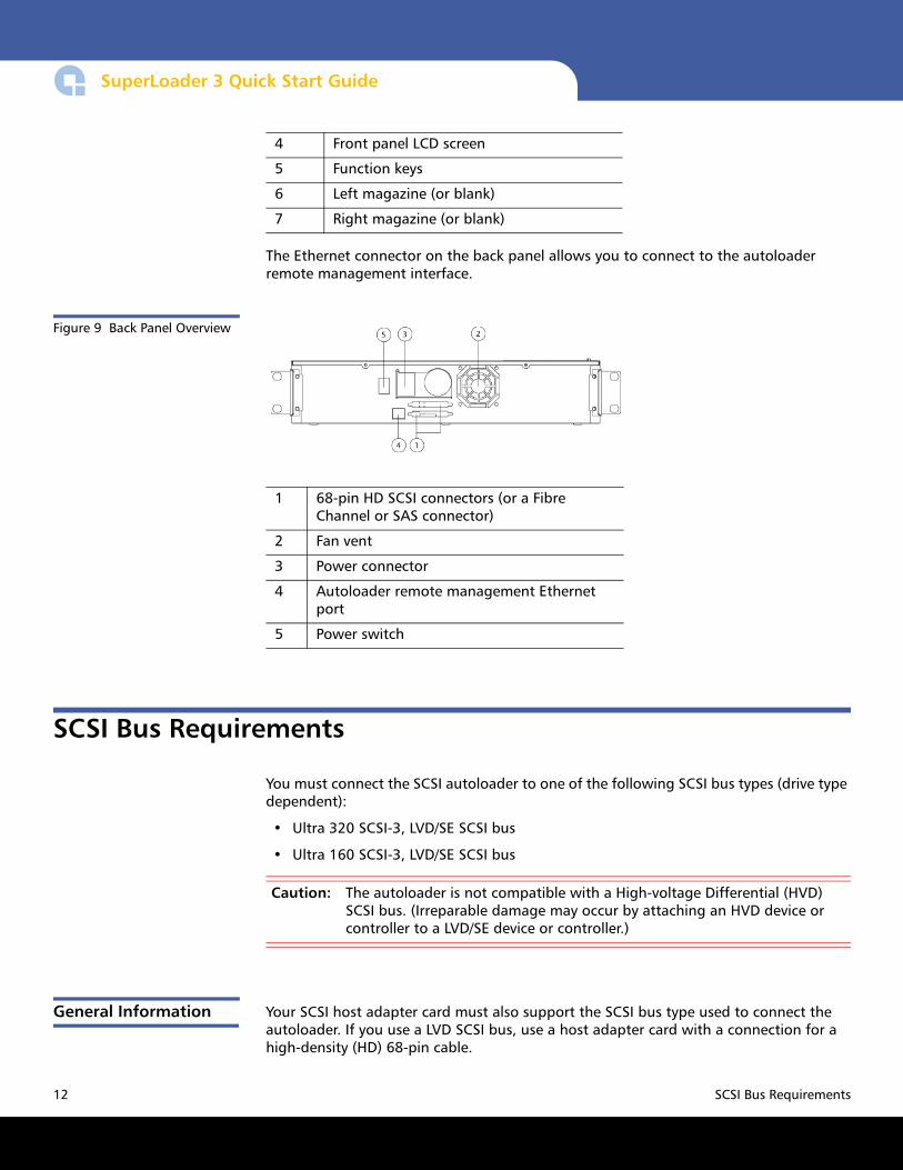
The Ethernet connector on the back panel allows you to connect to the autoloader remote management interface.
Figure 9 Back Panel Overview
1 68-pin HD SCSI connectors (or a Fibre Channel or SAS connector)
2 Fan vent
3 Power connector
4 Autoloader remote management Ethernet port
5 Power switch
SCSI Bus Requirements
You must connect the SCSI autoloader to one of the following SCSI bus types (drive type dependent):
• Ultra 320 SCSI-3, LVD/SE SCSI bus
• Ultra 160 SCSI-3, LVD/SE SCSI bus
Caution: The autoloader is not compatible with a High-voltage Differential (HVD) SCSI bus. (Irreparable damage may occur by attaching an HVD device or controller to a LVD/SE device or controller.)
General Information Your SCSI host adapter card must also support the SCSI bus type used to connect the autoloader. If you use a LVD SCSI bus, use a host adapter card with a connection for a high-density (HD) 68-pin cable.
4 Front panel LCD screen
5 Function keys
6 Left magazine (or blank)
7 Right magazine (or blank)
12 SCSI Bus Requirements
SuperLoader 3
Note: The maximum number of autoloaders supported per SCSI bus is two. The autoloader may not work with multiple SCSI LUNs when attached to a RAID controller. The autoloader is not recommended for use with a RAID controller. If this situation occurs, it is recommended that the autoloader be attached to a separate SCSI bus controller on the host or server.
Connecting SCSI, SAS, or Fibre Channel and Power Cables
To connect the SCSI, SAS (Serial Attached SCSI) or Fibre Channel and power cables to the autoloader, refer to the following sections:
SAS 1 and SAS 2 Connectors
The type of SAS connector on the back of the SuperLoader (SAS 1 or SAS 2) depends on the type of tape drive.
• LTO-3 and LTO-4 Tape Drives SAS Connectors
• LTO-5 Tape Drive SAS Connectors
LTO-3 and LTO-4 Tape Drives SAS Connectors
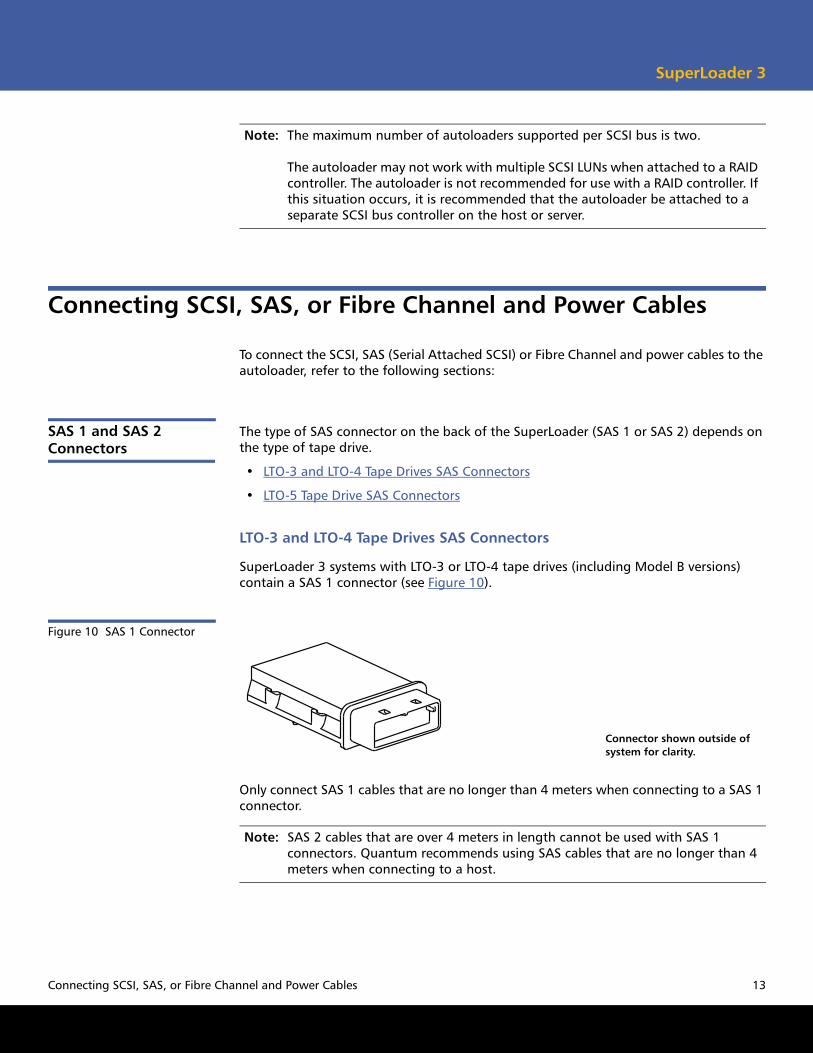
SuperLoader 3 systems with LTO-3 or LTO-4 tape drives (including Model B versions) contain a SAS 1 connector (see Figure 10).
Figure 10 SAS 1 Connector
Connector shown outside of system for clarity.
Only connect SAS 1 cables that are no longer than 4 meters when connecting to a SAS 1 connector.
Note: SAS 2 cables that are over 4 meters in length cannot be used with SAS 1 connectors. Quantum recommends using SAS cables that are no longer than 4 meters when connecting to a host.
Connecting SCSI, SAS, or Fibre Channel and Power Cables 13
SuperLoader 3 Quick Start Guide
LTO-5 Tape Drive SAS Connectors
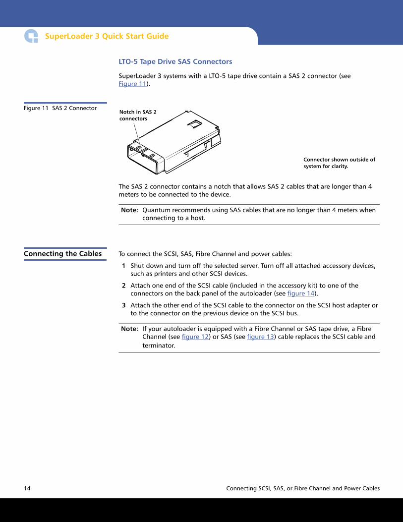
SuperLoader 3 systems with a LTO-5 tape drive contain a SAS 2 connector (see Figure 11).
Figure 11 SAS 2 Connector
Connector shown outside of system for clarity.
Notch in SAS 2 connectors
The SAS 2 connector contains a notch that allows SAS 2 cables that are longer than 4 meters to be connected to the device.
Note: Quantum recommends using SAS cables that are no longer than 4 meters when connecting to a host.
Connecting the Cables To connect the SCSI, SAS, Fibre Channel and power cables:
1 Shut down and turn off the selected server. Turn off all attached accessory devices, such as printers and other SCSI devices.
2 Attach one end of the SCSI cable (included in the accessory kit) to one of the connectors on the back panel of the autoloader (see figure 14).
3 Attach the other end of the SCSI cable to the connector on the SCSI host adapter or to the connector on the previous device on the SCSI bus.
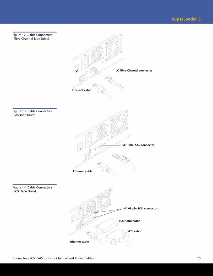
Note: If your autoloader is equipped with a Fibre Channel or SAS tape drive, a Fibre Channel (see figure 12) or SAS (see figure 13) cable replaces the SCSI cable and terminator.
14 Connecting SCSI, SAS, or Fibre Channel and Power Cables
SuperLoader 3
Figure 12 Cable Connectors (Fibre Channel Tape Drive)
Ethernet cable
LC Fibre Channel connector
Figure 13 Cable Connectors (SAS Tape Drive)
Ethernet cable
SFF 8088 SAS connector
Figure 14 Cable Connectors (SCSI Tape Drive)
SCSI terminator
SCSI cable
Ethernet cable
HD 68-pin SCSI connectors
Connecting SCSI, SAS, or Fibre Channel and Power Cables 15
SuperLoader 3 Quick Start Guide
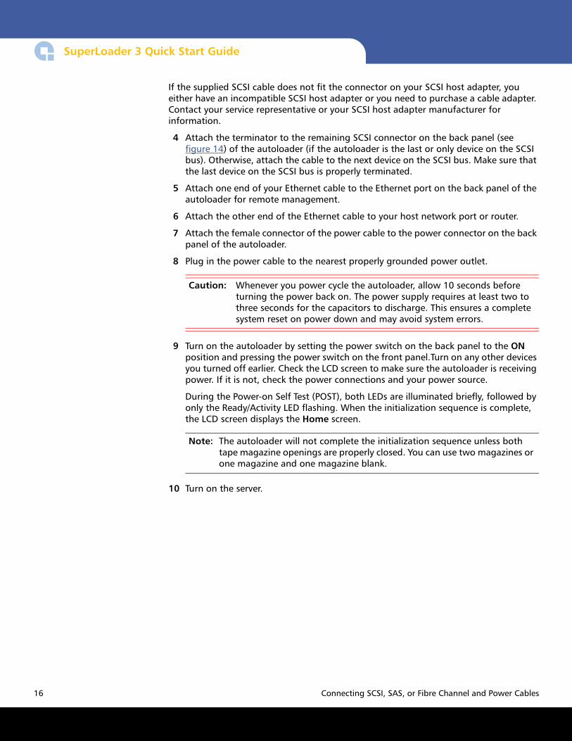
If the supplied SCSI cable does not fit the connector on your SCSI host adapter, you either have an incompatible SCSI host adapter or you need to purchase a cable adapter. Contact your service representative or your SCSI host adapter manufacturer for information.
4 Attach the terminator to the remaining SCSI connector on the back panel (see figure 14) of the autoloader (if the autoloader is the last or only device on the SCSI bus). Otherwise, attach the cable to the next device on the SCSI bus. Make sure that the last device on the SCSI bus is properly terminated.
5 Attach one end of your Ethernet cable to the Ethernet port on the back panel of the autoloader for remote management.
6 Attach the other end of the Ethernet cable to your host network port or router.
7 Attach the female connector of the power cable to the power connector on the back panel of the autoloader.
8 Plug in the power cable to the nearest properly grounded power outlet.
Caution: Whenever you power cycle the autoloader, allow 10 seconds before turning the power back on. The power supply requires at least two to three seconds for the capacitors to discharge. This ensures a complete system reset on power down and may avoid system errors.
9 Turn on the autoloader by setting the power switch on the back panel to the ON position and pressing the power switch on the front panel.Turn on any other devices you turned off earlier. Check the LCD screen to make sure the autoloader is receiving power. If it is not, check the power connections and your power source.
During the Power-on Self Test (POST), both LEDs are illuminated briefly, followed by only the Ready/Activity LED flashing. When the initialization sequence is complete, the LCD screen displays the Home screen.
Note: The autoloader will not complete the initialization sequence unless both tape magazine openings are properly closed. You can use two magazines or one magazine and one magazine blank.
10 Turn on the server.
16 Connecting SCSI, SAS, or Fibre Channel and Power Cables

SuperLoader 3
Setting the SCSI ID
Each SCSI device attached to a server or workstation must have a unique SCSI ID from 0 through 7. The default SCSI ID is 5 for the SuperLoader 3.
To change the SCSI ID for the SuperLoader 3:
1 If the main menu is not already visible, press Enter.
2 On the main menu, scroll to Configuration and press Enter.
3 On the Configuration submenu, scroll to SCSI ID and press Enter.
4 Scroll to the number you want to set as the autoloader's SCSI ID, then press Enter.
Cycle Power new SCSI ID appears on the LCD.
5 Press and hold the power button on the front panel until System Shutdown wait 60 sec appears on the LCD.
Power Off appears on the LCD, then the autoloader shuts off.
6 Press the power button again to power on the autoloader.
The new SCSI ID is now in effect.
Preparing the Host and Verifying the Connection
If necessary, install a SCSI, Fibre Channel, or SAS host adapter, software, and compatible drivers. Refer to the manuals for the host computer and SCSI, Fibre Channel, or SAS host adapter for detailed instructions. In addition, follow these general guidelines:
• When the host server is powered on, install software, and/or drivers that are compatible with the autoloader (see Windows Operating System Support). Software compatibility information is available at www.quantum.com. Most backup software packages require an additional module to communicate with the autoloader robotics.
• If the host server is connected to a network, check with the system administrator before turning off power.
• Use proper procedures to prevent electrostatic discharge (ESD). Use wrist-grounding straps and anti-static mats when handling internal components.
• Make sure that the host server has an open expansion slot.
• Make sure that your backup application supports the SCSI, Fibre Channel, or SAS host adapter.
• For the SCSI autoloader interface:
• Depending on the server configuration, you may need to change the SCSI ID of the autoloader (see Setting the SCSI ID).
Setting the SCSI ID 17

SuperLoader 3 Quick Start Guide
• Ensure the autoloader is properly terminated. If the autoloader is the only SCSI device other than the SCSI host adapter on the selected SCSI bus, it must be terminated. Likewise, if the autoloader is physically the last SCSI device on the SCSI bus, it must be terminated. Only the devices physically at the beginning and end of the SCSI bus should be terminated. If the host is located at the beginning of the SCSI bus, the host should already have a terminator installed.
• Verify the connection between the autoloader and host by going to Settings>Control Panel>System>Hardware>Device Manager>Tape Drive and/or Media Changer in Microsoft® Windows® 2000, Microsoft Windows XP and Windows Server® 2003. For more information on verifying the connection of SCSI devices, consult the operating system documentation.
Windows Operating System Support
There are two device drivers associated with the SuperLoader 3 autoloader. One for the autoloader itself, and a second for the tape drive within the autoloader.
Note: Device drivers are required if you intend to use the Microsoft Windows native backup application. Commercial backup applications provide all necessary device driver support. Refer to www.quantum.com for a list of compatible backup applications. Please note that Microsoft Windows NT® does not include native support for autoloaders. A backup application must be used if using the SuperLoader 3 under Microsoft Windows NT.
Autoloader Device Driver
For the SuperLoader 3 device driver, go to:
• http://www.quantum.com/ServiceandSupport/SoftwareandDocumentationDownloads/SuperLoader3/Index.aspx#Drivers.
18 Windows Operating System Support
SuperLoader 3
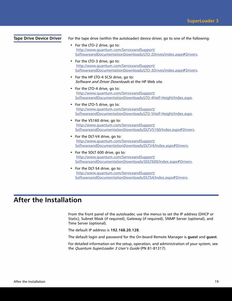
Tape Drive Device Driver For the tape drive (within the autoloader) device driver, go to one of the following:
• For the LTO-2 drive, go to: http://www.quantum.com/ServiceandSupport/SoftwareandDocumentationDownloads/LTO-2Drives/Index.aspx#Drivers.
• For the LTO-3 drive, go to: http://www.quantum.com/ServiceandSupport/SoftwareandDocumentationDownloads/LTO-3Drives/Index.aspx#Drivers.
• For the HP LTO-4 SCSI drive, go to: Software and Driver Downloads at the HP Web site.
• For the LTO-4 drive, go to: http://www.quantum.com/ServiceandSupport/SoftwareandDocumentationDownloads/LTO-4Half-Height/Index.aspx.
• For the LTO-5 drive, go to: http://www.quantum.com/ServiceandSupport/SoftwareandDocumentationDownloads/LTO-5Half-Height/Index.aspx.
• For the VS160 drive, go to: http://www.quantum.com/ServiceandSupport/SoftwareandDocumentationDownloads/DLTVS160/Index.aspx#Drivers.
• For the DLT-V4 drive, go to: http://www.quantum.com/ServiceandSupport/SoftwareandDocumentationDownloads/DLTV4/Index.aspx#Drivers.
• For the SDLT 600 drive, go to: http://www.quantum.com/ServiceandSupport/SoftwareandDocumentationDownloads/SDLT600/Index.aspx#Drivers.
• For the DLT-S4 drive, go to: http://www.quantum.com/ServiceandSupport/SoftwareandDocumentationDownloads/DLTS4/Index.aspx#Drivers.
After the Installation
From the front panel of the autoloader, use the menus to set the IP address (DHCP or Static), Subnet Mask (if required), Gateway (if required), SNMP Server (optional), and Time Server (optional).
The default IP address is 192.168.20.128.
The default login and password for the On-board Remote Manager is guest and guest.
For detailed information on the setup, operation, and administration of your system, see the Quantum SuperLoader 3 User’s Guide (PN 81-81317).
After the Installation 19

SuperLoader 3 Quick Start Guide
Backup. Recovery. Archive. It’s What We Do.
©2010 Quantum Corporation. All rights reserved. Quantum, the Quantum logo, and all other logos are registered trademarks of Quantum Corporation or of their respective owners. Protected by Pending and Issued U.S. and Foreign Patents, including U.S. Patent No. 5,990,810.
For assistance, contact the Quantum Customer Support Center:USA: 800-284-5101 (toll free) or 949-725-2100EMEA: 00800-4-782-6886 (toll free) or +49 6131 3241 1164APAC: +800 7826 8887 (toll free) or +603 7953 3010Worldwide: http://www.quantum.com/ServiceandSupport
About Quantum
Quantum Corp. (NYSE:QTM) is the leading global storage company specializing in backup, recovery and archive. Combining focused expertise, customer-driven innovation, and platform independence, Quantum provides a comprehensive range of disk, tape, media and software solutions supported by a world-class sales and service organization. This includes the DXi™-Series, the first disk backup solutions to extend the power of data deduplication and replication across the distributed enterprise. As a long-standing and trusted partner, the company works closely with a broad network of resellers, OEMs and other suppliers to meet customers’ evolving data protection needs.
*81-81313-05*20 81-81313-05 Rev A, February 2010