Embed Size (px)
Citation preview
QUEST JUICE2 and 4 Flavor
Training Manual
Release Date: April 12, 2004
Publication Number: TP00968
Revision Date: November 23, 2004
Revision: C
Visit the IMI Cornelius web site at www.cornelius.com for all your Literature needs.
Quest Juice Training ManualThe products, technical information, and instructions contained in this manual are subject to change without notice. These instructions are not intended to cover all details or varia-tions of the equipment, nor to provide for every possible contingency in the installation, operation or maintenance of this equipment. This manual assumes that the person(s) working on the equipment have been trained and are skilled in working with electrical, plumbing, pneumatic, and mechanical equipment. It is assumed that appropriate safety precautions are taken and that all local safety and construction requirements are being met, in addition to the information contained in this manual.
To inquire about current revisions of this and other documentation or for assistance with any Cornelius product contact:
IMI Cornelius Inc.
Phone: 800-238-3600
Internet: www.cornelius.com
Trademarks and copyrights:
Aurora, Cornelius, Decade, Hydro Boost, Sitco, Spirit, UF-1, Vanguard, Venture, and Vista are registered trademarks of IMI Cornelius Inc.
Optifill trademark is pending.
This document contains proprietary information and it may not be reproduced in any way without permission from Cornelius.
Printed in U.S.A.
Copyright © 2004, All Rights Reserved, IMI Cornelius Inc.
Quest Juice Training Manual
© 2004, IMI Cornelius Inc. - i - Publication Number: TP00968
TABLE OF CONTENTSOverview . . . . . . . . . . . . . . . . . . . . . . . . . . . . . . . . . . . . . . . . . . . . . . . . . . . . . . . . . . . . .1
Product Description . . . . . . . . . . . . . . . . . . . . . . . . . . . . . . . . . . . . . . . . . . . . . . . . . . .1Dimensions & Capacities . . . . . . . . . . . . . . . . . . . . . . . . . . . . . . . . . . . . . . . . . . . . . .2
Quest . . . . . . . . . . . . . . . . . . . . . . . . . . . . . . . . . . . . . . . . . . . . . . . . . . . . . . . . . . .2Quest, Two Flavor . . . . . . . . . . . . . . . . . . . . . . . . . . . . . . . . . . . . . . . . . . . . . . . . .2Quest, Four Flavor . . . . . . . . . . . . . . . . . . . . . . . . . . . . . . . . . . . . . . . . . . . . . . . .2IPD Times . . . . . . . . . . . . . . . . . . . . . . . . . . . . . . . . . . . . . . . . . . . . . . . . . . . . . . .2Ice Bath Capacity . . . . . . . . . . . . . . . . . . . . . . . . . . . . . . . . . . . . . . . . . . . . . . . . .2
System Details . . . . . . . . . . . . . . . . . . . . . . . . . . . . . . . . . . . . . . . . . . . . . . . . . . . . . . . .3Water . . . . . . . . . . . . . . . . . . . . . . . . . . . . . . . . . . . . . . . . . . . . . . . . . . . . . . . . . . . . .3
Water Quality . . . . . . . . . . . . . . . . . . . . . . . . . . . . . . . . . . . . . . . . . . . . . . . . . . . .3Water Flow . . . . . . . . . . . . . . . . . . . . . . . . . . . . . . . . . . . . . . . . . . . . . . . . . . . . . .3Adjusting Flow Rates . . . . . . . . . . . . . . . . . . . . . . . . . . . . . . . . . . . . . . . . . . . . . .3
Concentrate . . . . . . . . . . . . . . . . . . . . . . . . . . . . . . . . . . . . . . . . . . . . . . . . . . . . . . . .3Setting the Brix . . . . . . . . . . . . . . . . . . . . . . . . . . . . . . . . . . . . . . . . . . . . . . . . . . . . . .3
Introduction . . . . . . . . . . . . . . . . . . . . . . . . . . . . . . . . . . . . . . . . . . . . . . . . . . . . . . . . . . .4Preview Questions . . . . . . . . . . . . . . . . . . . . . . . . . . . . . . . . . . . . . . . . . . . . . . . . . . .4Key Things To Know / Do . . . . . . . . . . . . . . . . . . . . . . . . . . . . . . . . . . . . . . . . . . . . . .4
Installation . . . . . . . . . . . . . . . . . . . . . . . . . . . . . . . . . . . . . . . . . . . . . . . . . . . . . . . . . . . .5Counter Location . . . . . . . . . . . . . . . . . . . . . . . . . . . . . . . . . . . . . . . . . . . . . . . . . . . . .5Filling the Ice Bath . . . . . . . . . . . . . . . . . . . . . . . . . . . . . . . . . . . . . . . . . . . . . . . . . . .5Connecting Water Supply . . . . . . . . . . . . . . . . . . . . . . . . . . . . . . . . . . . . . . . . . . . . . .5Priming/Flushing Water System . . . . . . . . . . . . . . . . . . . . . . . . . . . . . . . . . . . . . . . . .5
Concentrate Handling & Loading . . . . . . . . . . . . . . . . . . . . . . . . . . . . . . . . . . . . . . . . .6Loading Concentrate . . . . . . . . . . . . . . . . . . . . . . . . . . . . . . . . . . . . . . . . . . . . . . . . . .6Changing Concentrate Containers: . . . . . . . . . . . . . . . . . . . . . . . . . . . . . . . . . . . . . . .6Supplies . . . . . . . . . . . . . . . . . . . . . . . . . . . . . . . . . . . . . . . . . . . . . . . . . . . . . . . . . . .7Checking/Adjusting the Brix Setting . . . . . . . . . . . . . . . . . . . . . . . . . . . . . . . . . . . . . .7Programming the Portion Control . . . . . . . . . . . . . . . . . . . . . . . . . . . . . . . . . . . . . . . .8
Cancel/Pour Button . . . . . . . . . . . . . . . . . . . . . . . . . . . . . . . . . . . . . . . . . . . . . . . .8
Planned Maintenance Schedule . . . . . . . . . . . . . . . . . . . . . . . . . . . . . . . . . . . . . . . . . .9Daily . . . . . . . . . . . . . . . . . . . . . . . . . . . . . . . . . . . . . . . . . . . . . . . . . . . . . . . . . . . . . .9
Flush System: . . . . . . . . . . . . . . . . . . . . . . . . . . . . . . . . . . . . . . . . . . . . . . . . . . . .9Clean Splash Zones & Dispense Nozzles: . . . . . . . . . . . . . . . . . . . . . . . . . . . . . .9
Weekly . . . . . . . . . . . . . . . . . . . . . . . . . . . . . . . . . . . . . . . . . . . . . . . . . . . . . . . . . . . .9Sanitize the Juice Dispenser: . . . . . . . . . . . . . . . . . . . . . . . . . . . . . . . . . . . . . . . .9
Semi-Annual . . . . . . . . . . . . . . . . . . . . . . . . . . . . . . . . . . . . . . . . . . . . . . . . . . . . . . .10Clean Water Inlet Strainer: . . . . . . . . . . . . . . . . . . . . . . . . . . . . . . . . . . . . . . . . .10Clean Chassis Interior: . . . . . . . . . . . . . . . . . . . . . . . . . . . . . . . . . . . . . . . . . . . .10Check and Top-Off Water Ice Bath: . . . . . . . . . . . . . . . . . . . . . . . . . . . . . . . . . .10
Annually . . . . . . . . . . . . . . . . . . . . . . . . . . . . . . . . . . . . . . . . . . . . . . . . . . . . . . . . . .11Replace Pump Tubing: . . . . . . . . . . . . . . . . . . . . . . . . . . . . . . . . . . . . . . . . . . . .11Removing Pump Platform(s): . . . . . . . . . . . . . . . . . . . . . . . . . . . . . . . . . . . . . . .11Replacing Pump Tubing: . . . . . . . . . . . . . . . . . . . . . . . . . . . . . . . . . . . . . . . . . . .11
Mechanical Section . . . . . . . . . . . . . . . . . . . . . . . . . . . . . . . . . . . . . . . . . . . . . . . . . . . .13
Quest Juice Training Manual
Publication Number: TP00968 - ii - © 2004, IMI Cornelius Inc.
Removal of Merchandiser . . . . . . . . . . . . . . . . . . . . . . . . . . . . . . . . . . . . . . . . . . . .13Removal of the Switch Panel . . . . . . . . . . . . . . . . . . . . . . . . . . . . . . . . . . . . . . . . . . 14Removal of the Pump Platforms . . . . . . . . . . . . . . . . . . . . . . . . . . . . . . . . . . . . . . . . 15Removal of the Cooling Fan . . . . . . . . . . . . . . . . . . . . . . . . . . . . . . . . . . . . . . . . . . . 17Removal of Panels . . . . . . . . . . . . . . . . . . . . . . . . . . . . . . . . . . . . . . . . . . . . . . . . . . 18Removal of Electrical Box . . . . . . . . . . . . . . . . . . . . . . . . . . . . . . . . . . . . . . . . . . . .19Removal of the VRB Boards . . . . . . . . . . . . . . . . . . . . . . . . . . . . . . . . . . . . . . . . . . 20Removal of the Ice Bank Control . . . . . . . . . . . . . . . . . . . . . . . . . . . . . . . . . . . . . . . 21Removal of Nozzle Guide Gasket . . . . . . . . . . . . . . . . . . . . . . . . . . . . . . . . . . . . . . 21Removal of the Cooling Cabinet . . . . . . . . . . . . . . . . . . . . . . . . . . . . . . . . . . . . . . . . 22Removal of the Agitator Motor . . . . . . . . . . . . . . . . . . . . . . . . . . . . . . . . . . . . . . . . . 24Removal of the Refrigeration Chassis . . . . . . . . . . . . . . . . . . . . . . . . . . . . . . . . . . . 24Removal of the Ice Control Probe . . . . . . . . . . . . . . . . . . . . . . . . . . . . . . . . . . . . . . 26
Major Component Review . . . . . . . . . . . . . . . . . . . . . . . . . . . . . . . . . . . . . . . . . . . . . . 27Electrical Box . . . . . . . . . . . . . . . . . . . . . . . . . . . . . . . . . . . . . . . . . . . . . . . . . . . . . . 27Pump Speed Switch . . . . . . . . . . . . . . . . . . . . . . . . . . . . . . . . . . . . . . . . . . . . . . . . . 28Ice Bank Control . . . . . . . . . . . . . . . . . . . . . . . . . . . . . . . . . . . . . . . . . . . . . . . . . . . . 28
Operational Overview . . . . . . . . . . . . . . . . . . . . . . . . . . . . . . . . . . . . . . . . . . . . . 28Validating Operation . . . . . . . . . . . . . . . . . . . . . . . . . . . . . . . . . . . . . . . . . . . . . . 28
Transformer . . . . . . . . . . . . . . . . . . . . . . . . . . . . . . . . . . . . . . . . . . . . . . . . . . . . . . . 29Water Inlet Solenoid . . . . . . . . . . . . . . . . . . . . . . . . . . . . . . . . . . . . . . . . . . . . . . . . . 29Door Switch - 72 B Serial Number . . . . . . . . . . . . . . . . . . . . . . . . . . . . . . . . . . . . . . 29Door Switch - 72 E Serial Number . . . . . . . . . . . . . . . . . . . . . . . . . . . . . . . . . . . . . . 30Platform Components . . . . . . . . . . . . . . . . . . . . . . . . . . . . . . . . . . . . . . . . . . . . . . . . 30
Water Valve/Flow Control . . . . . . . . . . . . . . . . . . . . . . . . . . . . . . . . . . . . . . . . . . 30Bottle Adaptor - O-rings . . . . . . . . . . . . . . . . . . . . . . . . . . . . . . . . . . . . . . . . . . .30Bottle Adaptor - Sold Out Sensors . . . . . . . . . . . . . . . . . . . . . . . . . . . . . . . . . . . 31Bottle Adaptor - Tray Grommets . . . . . . . . . . . . . . . . . . . . . . . . . . . . . . . . . . . . .31Bottle Adaptor - Flush Mode . . . . . . . . . . . . . . . . . . . . . . . . . . . . . . . . . . . . . . . . 32Static Mixers . . . . . . . . . . . . . . . . . . . . . . . . . . . . . . . . . . . . . . . . . . . . . . . . . . . . 32
Wiring Diagram . . . . . . . . . . . . . . . . . . . . . . . . . . . . . . . . . . . . . . . . . . . . . . . . . . . . . 33
Troubleshooting Guide . . . . . . . . . . . . . . . . . . . . . . . . . . . . . . . . . . . . . . . . . . . . . . . . 35
Notes . . . . . . . . . . . . . . . . . . . . . . . . . . . . . . . . . . . . . . . . . . . . . . . . . . . . . . . . . . . . . . . 38
Quest Juice Training Manual
© 2004, IMI Cornelius Inc. - 1 - Publication Number: TP00968
OVERVIEW
PRODUCT DESCRIPTION
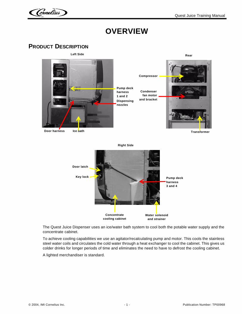
The Quest Juice Dispenser uses an ice/water bath system to cool both the potable water supply and the concentrate cabinet.
To achieve cooling capabilities we use an agitator/recalculating pump and motor. This cools the stainless steel water coils and circulates the cold water through a heat exchanger to cool the cabinet. This gives us colder drinks for longer periods of time and eliminates the need to have to defrost the cooling cabinet.
A lighted merchandiser is standard.
Ice bathDoor harness
Pump deck harness 1 and 2
Dispensing nozzles
Left Side
Transformer
Condenserfan motor
and bracket
Compressor
Rear
Concentrate cooling cabinet
Water solenoid and strainer
Door latch
Right Side
Key lock Pump deck harness 3 and 4
Quest Juice Training Manual
Publication Number: TP00968 - 2 - © 2004, IMI Cornelius Inc.
DIMENSIONS & CAPACITIES
QuestDispense Rate ........................................1.0 – 2.2 oz./sec.
Electrical rating .......................................115 VAC, 60 Hz, 15 amp dedicated circuit................................................................220 VAC, 50Hz
Dimensions .............................................29.3” H, 24.3” D
Condenser clearance..............................4” back, 12” top
Water Connection...................................3/8” SAE male flareWater Pressure.......................................80 psi max. static, 20 psi min. dynamicFor best results it should be regulated to 45 to 50 psi
Quest, Two FlavorDimensions .............................................10.4” W
Operating weight.....................................120 lbs.
Quest, Four FlavorDimensions .............................................15” W
Operating weight.....................................160 lbs.
IPD TimesQuest 4 ...................................................4.5 hours +
Quest 2 ...................................................3 hours
Ice Bath CapacityQuest 4 ...................................................3.6 gallons; 15-16 lbs of ice IPD
Quest 2 ...................................................1.8 gallons; 8-9 lbs of ice IPD
Quest Juice Training Manual
© 2004, IMI Cornelius Inc. - 3 - Publication Number: TP00968
SYSTEM DETAILSWATER
Water QualityWater quality has an affect on juice dispensing systems.
• odor• taste• clarity/foaming
Water filtration is recommended to assure the best beverage taste.
Water FlowInlet water pressure should be regulated to 45 to 50 psi max. (3.1 bar) to prevent damage to pump tub-ing. Minimum flowing pressure must be 20psi.
Flow RatesAdequate water flow is necessary and must be at least 3.0 ounces per second (89ml) at the inlet to the unit.
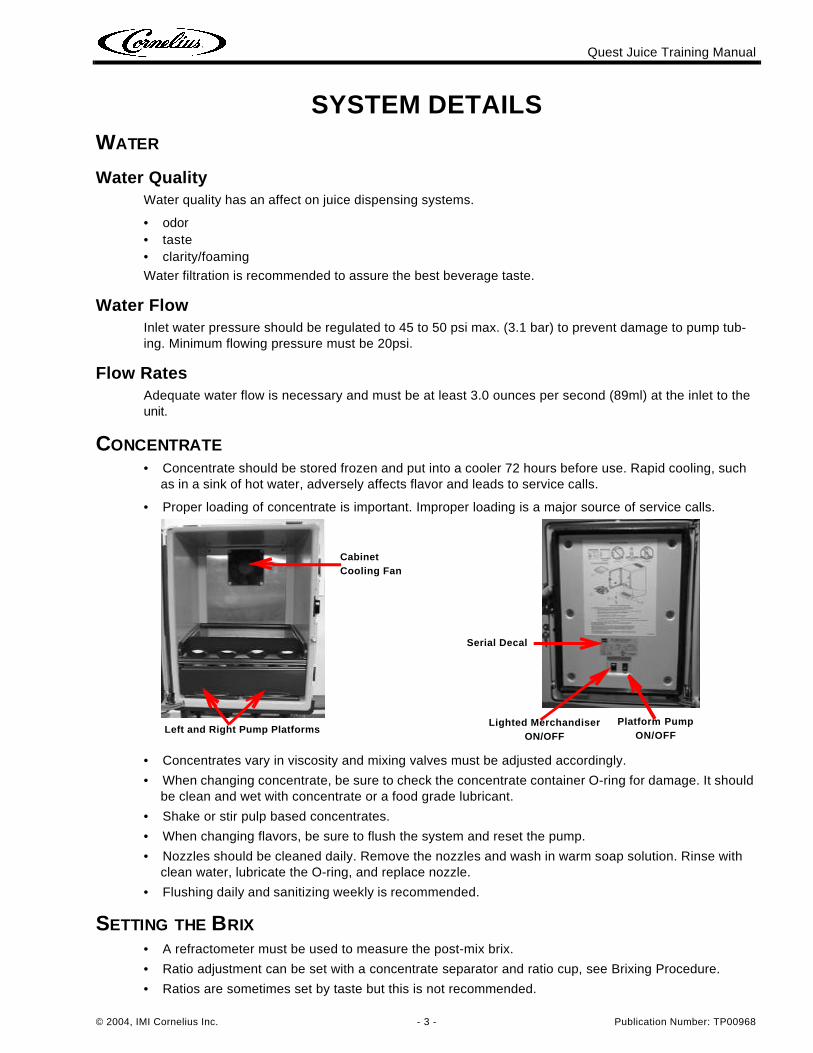
CONCENTRATE• Concentrate should be stored frozen and put into a cooler 72 hours before use. Rapid cooling, such
as in a sink of hot water, adversely affects flavor and leads to service calls.
• Proper loading of concentrate is important. Improper loading is a major source of service calls.
• Concentrates vary in viscosity and mixing valves must be adjusted accordingly.
• When changing concentrate, be sure to check the concentrate container O-ring for damage. It should be clean and wet with concentrate or a food grade lubricant.
• Shake or stir pulp based concentrates.
• When changing flavors, be sure to flush the system and reset the pump.
• Nozzles should be cleaned daily. Remove the nozzles and wash in warm soap solution. Rinse with clean water, lubricate the O-ring, and replace nozzle.
• Flushing daily and sanitizing weekly is recommended.
SETTING THE BRIX• A refractometer must be used to measure the post-mix brix.
• Ratio adjustment can be set with a concentrate separator and ratio cup, see Brixing Procedure.
• Ratios are sometimes set by taste but this is not recommended.
Cabinet Cooling Fan
Serial Decal
Lighted Merchandiser ON/OFF
Left and Right Pump PlatformsPlatform Pump
ON/OFF
Quest Juice Training Manual
Publication Number: TP00968 - 4 - © 2004, IMI Cornelius Inc.
INTRODUCTIONPREVIEW QUESTIONS
Check your current knowledge by taking a few minutes to answer the following questions:
1. The ice bank control is adjustable? _____ True _____ False2. The transformer does NOT control the cooling system? _____ True _____ False
3. Condenser airflow passes over the compressor first? _____ True _____ False
4. ”Ratio” refers to the amount of water required to dilute one part of concentrate?_____ True _____ False
5. O-rings may be installed dry (lubrication is not recommended)?_____ True _____ False
KEY THINGS TO KNOW / DO• Work Safely! Always unplug/disconnect the power to the dispenser before servicing, and get help lift-
ing the unit if it must be removed from the counter.
• Make certain that the water line has adequate pressure at all times!
• Learn to use a good quality volt-ohm meter. Proper electrical trouble shooting is impossible without it!
• 40-50 PSI dynamic water pressure measured at the dispenser inlet with 3.0 ounces a second. Water pressure must not exceed 80 lbs static with a minimum flowing pressure of 30 PSI.
• Never leave the Dispense/Flush lever in the Flush position, it can cause the pump tubing to burst.
Quest Juice Training Manual
© 2004, IMI Cornelius Inc. - 5 - Publication Number: TP00968
INSTALLATIONCOUNTER LOCATION
The minimum airflow clearance is: 4” (10.16 cm) in back and 12” (30.48 cm) on top and open to the front.
IMPORTANT: Condenser air is drawn in from the bottom of the rear panel and discharged out the top of the rear panel. Failure to maintain clearance space will reduce capacity of the unit and cause premature compressor failure.
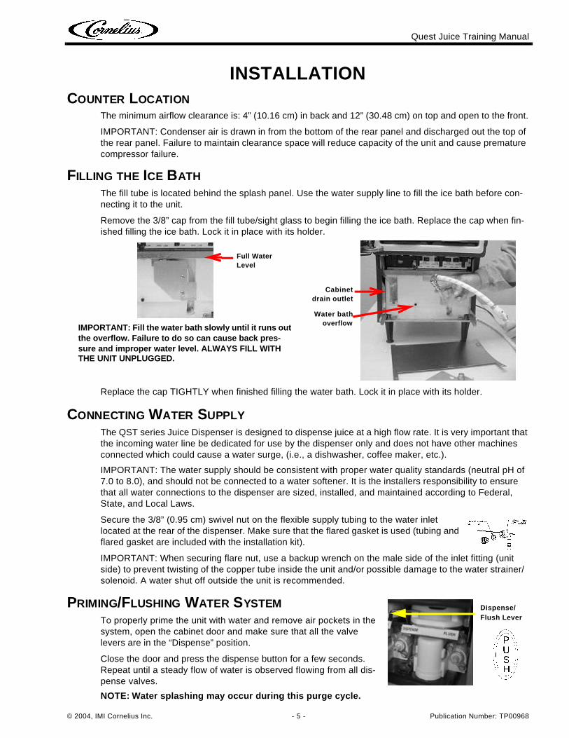
FILLING THE ICE BATHThe fill tube is located behind the splash panel. Use the water supply line to fill the ice bath before con-necting it to the unit.
Remove the 3/8” cap from the fill tube/sight glass to begin filling the ice bath. Replace the cap when fin-ished filling the ice bath. Lock it in place with its holder.
Replace the cap TIGHTLY when finished filling the water bath. Lock it in place with its holder.
CONNECTING WATER SUPPLYThe QST series Juice Dispenser is designed to dispense juice at a high flow rate. It is very important that the incoming water line be dedicated for use by the dispenser only and does not have other machines connected which could cause a water surge, (i.e., a dishwasher, coffee maker, etc.).
IMPORTANT: The water supply should be consistent with proper water quality standards (neutral pH of 7.0 to 8.0), and should not be connected to a water softener. It is the installers responsibility to ensure that all water connections to the dispenser are sized, installed, and maintained according to Federal, State, and Local Laws.
Secure the 3/8” (0.95 cm) swivel nut on the flexible supply tubing to the water inlet located at the rear of the dispenser. Make sure that the flared gasket is used (tubing and flared gasket are included with the installation kit).
IMPORTANT: When securing flare nut, use a backup wrench on the male side of the inlet fitting (unit side) to prevent twisting of the copper tube inside the unit and/or possible damage to the water strainer/solenoid. A water shut off outside the unit is recommended.
PRIMING/FLUSHING WATER SYSTEMTo properly prime the unit with water and remove air pockets in the system, open the cabinet door and make sure that all the valve levers are in the “Dispense” position.
Close the door and press the dispense button for a few seconds. Repeat until a steady flow of water is observed flowing from all dis-pense valves.
NOTE: Water splashing may occur during this purge cycle.
IMPORTANT: Fill the water bath slowly until it runs out the overflow. Failure to do so can cause back pres-sure and improper water level. ALWAYS FILL WITH THE UNIT UNPLUGGED.
Full Water Level
Water bathoverflow
Cabinetdrain outlet
Dispense/Flush Lever
Quest Juice Training Manual
Publication Number: TP00968 - 6 - © 2004, IMI Cornelius Inc.
CONCENTRATE HANDLING & LOADINGIt is recommended that the concentrate be thawed in a refrigerated 35°F-40°F (1.6°C-4.4°C) compart-ment for a minimum of 48 hours prior to loading into the Quest Juice Dispenser.
WARNING: Concentrate must be completely thawed and within the temperature range of 35°F-40°F (1.6°C-4.4°C) prior to loading. Failing to supply concentrate inside the recommended tem-perature range, especially below 35°F (1.6°C), will cause an out of brix drink (refer to the BrixingProcedure section for details).
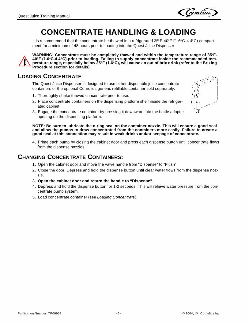
LOADING CONCENTRATEThe Quest Juice Dispenser is designed to use either disposable juice concentrate containers or the optional Cornelius generic refillable container sold separately.
1. Thoroughly shake thawed concentrate prior to use.
2. Place concentrate containers on the dispensing platform shelf inside the refriger-ated cabinet.
3. Engage the concentrate container by pressing it downward into the bottle adapter opening on the dispensing platform.
NOTE: Be sure to lubricate the o-ring seal on the container nozzle. This will ensure a good sealand allow the pumps to draw concentrated from the containers more easily. Failure to create agood seal at this connection may result in weak drinks and/or seepage of concentrate.
4. Prime each pump by closing the cabinet door and press each dispense button until concentrate flows from the dispense nozzles.
CHANGING CONCENTRATE CONTAINERS:1. Open the cabinet door and move the valve handle from “Dispense” to “Flush”
2. Close the door. Depress and hold the dispense button until clear water flows from the dispense noz-zle.
3. Open the cabinet door and return the handle to “Dispense”.4. Depress and hold the dispense button for 1-2 seconds. This will relieve water pressure from the con-
centrate pump system.
5. Load concentrate container (see Loading Concentrate).
Quest Juice Training Manual
© 2004, IMI Cornelius Inc. - 7 - Publication Number: TP00968
BRIXING PROCEDURE
NOTE: If concentrate is not properly thawed, it will adversely affect the amount of concentrate dispensed. Thawed product should be between 35°F/1.6°C to 40°F/4.4°C.
NOTE: You can not dispense drinks with the door open.
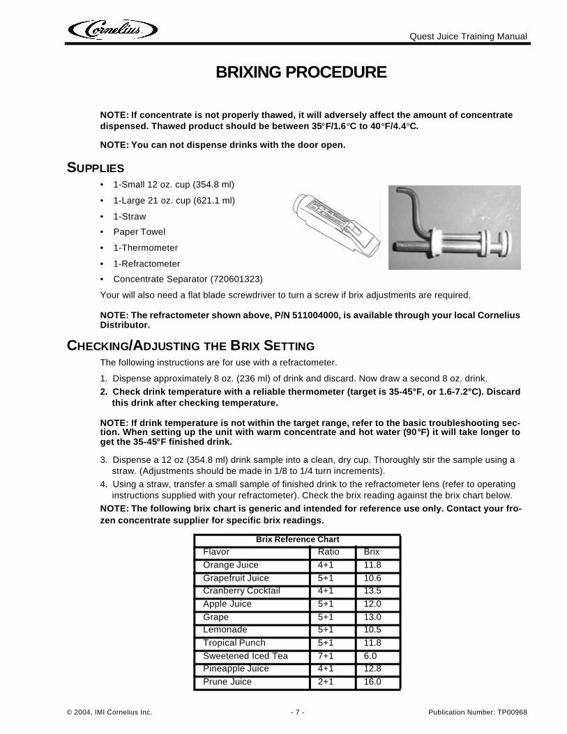
SUPPLIES• 1-Small 12 oz. cup (354.8 ml)
• 1-Large 21 oz. cup (621.1 ml)
• 1-Straw
• Paper Towel
• 1-Thermometer
• 1-Refractometer
• Concentrate Separator (720601323)
Your will also need a flat blade screwdriver to turn a screw if brix adjustments are required.
NOTE: The refractometer shown above, P/N 511004000, is available through your local CorneliusDistributor.
CHECKING/ADJUSTING THE BRIX SETTINGThe following instructions are for use with a refractometer.
1. Dispense approximately 8 oz. (236 ml) of drink and discard. Now draw a second 8 oz. drink.
2. Check drink temperature with a reliable thermometer (target is 35-45°F, or 1.6-7.2°C). Discard this drink after checking temperature.
NOTE: If drink temperature is not within the target range, refer to the basic troubleshooting sec-tion. When setting up the unit with warm concentrate and hot water (90°F) it will take longer toget the 35-45°F finished drink.
3. Dispense a 12 oz (354.8 ml) drink sample into a clean, dry cup. Thoroughly stir the sample using a straw. (Adjustments should be made in 1/8 to 1/4 turn increments).
4. Using a straw, transfer a small sample of finished drink to the refractometer lens (refer to operating instructions supplied with your refractometer). Check the brix reading against the brix chart below.
NOTE: The following brix chart is generic and intended for reference use only. Contact your fro-zen concentrate supplier for specific brix readings.
Brix Reference Chart
Flavor Ratio Brix
Orange Juice 4+1 11.8
Grapefruit Juice 5+1 10.6Cranberry Cocktail 4+1 13.5
Apple Juice 5+1 12.0
Grape 5+1 13.0Lemonade 5+1 10.5
Tropical Punch 5+1 11.8
Sweetened Iced Tea 7+1 6.0Pineapple Juice 4+1 12.8
Prune Juice 2+1 16.0
Quest Juice Training Manual
Publication Number: TP00968 - 8 - © 2004, IMI Cornelius Inc.
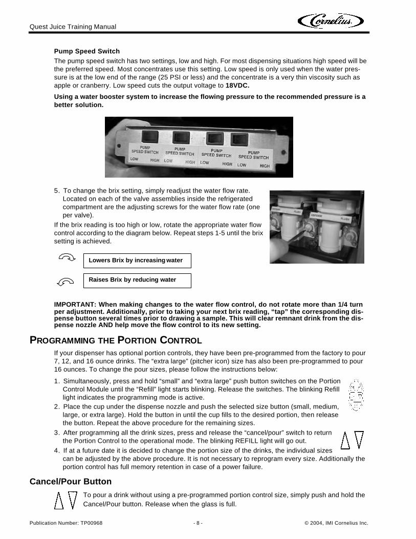
Pump Speed SwitchThe pump speed switch has two settings, low and high. For most dispensing situations high speed will be the preferred speed. Most concentrates use this setting. Low speed is only used when the water pres-sure is at the low end of the range (25 PSI or less) and the concentrate is a very thin viscosity such as apple or cranberry. Low speed cuts the output voltage to 18VDC.
Using a water booster system to increase the flowing pressure to the recommended pressure is a better solution.
5. To change the brix setting, simply readjust the water flow rate. Located on each of the valve assemblies inside the refrigerated compartment are the adjusting screws for the water flow rate (one per valve).
If the brix reading is too high or low, rotate the appropriate water flow control according to the diagram below. Repeat steps 1-5 until the brix setting is achieved.
IMPORTANT: When making changes to the water flow control, do not rotate more than 1/4 turnper adjustment. Additionally, prior to taking your next brix reading, “tap” the corresponding dis-pense button several times prior to drawing a sample. This will clear remnant drink from the dis-pense nozzle AND help move the flow control to its new setting.
PROGRAMMING THE PORTION CONTROLIf your dispenser has optional portion controls, they have been pre-programmed from the factory to pour 7, 12, and 16 ounce drinks. The “extra large” (pitcher icon) size has also been pre-programmed to pour 16 ounces. To change the pour sizes, please follow the instructions below:
1. Simultaneously, press and hold “small” and “extra large” push button switches on the Portion Control Module until the “Refill” light starts blinking. Release the switches. The blinking Refill light indicates the programming mode is active.
2. Place the cup under the dispense nozzle and push the selected size button (small, medium, large, or extra large). Hold the button in until the cup fills to the desired portion, then release the button. Repeat the above procedure for the remaining sizes.
3. After programming all the drink sizes, press and release the “cancel/pour” switch to return the Portion Control to the operational mode. The blinking REFILL light will go out.
4. If at a future date it is decided to change the portion size of the drinks, the individual sizes can be adjusted by the above procedure. It is not necessary to reprogram every size. Additionally the portion control has full memory retention in case of a power failure.
Cancel/Pour ButtonTo pour a drink without using a pre-programmed portion control size, simply push and hold the Cancel/Pour button. Release when the glass is full.
Lowers Brix by increasing water
Raises Brix by reducing water
Quest Juice Training Manual
© 2004, IMI Cornelius Inc. - 9 - Publication Number: TP00968
PLANNED MAINTENANCE SCHEDULEDAILY
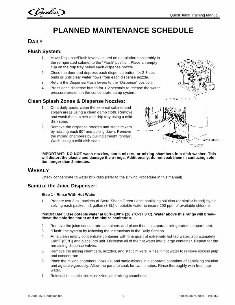
Flush System:1. Move Dispense/Flush levers located on the platform assembly in
the refrigerated cabinet to the “Flush” position. Place an empty cup on the drip tray below each dispense nozzle.
2. Close the door and depress each dispense button for 2-3 sec-onds or until clear water flows from each dispense nozzle.
3. Return the Dispense/Flush levers to the “Dispense” position.
4. Press each dispense button for 1-2 seconds to release the water pressure present in the concentrate pump system.
Clean Splash Zones & Dispense Nozzles:1. On a daily basis, clean the external cabinet and
splash areas using a clean damp cloth. Remove and wash the cup rest and drip tray using a mild dish soap.
2. Remove the dispense nozzles and static mixers by rotating each 90° and pulling down. Remove the mixing chambers by pulling straight forward. Wash using a mild dish soap.
IMPORTANT: DO NOT wash nozzles, static mixers, or mixing chambers in a dish washer. Thiswill distort the plastic and damage the o-rings. Additionally, do not soak them in sanitizing solu-tion longer than 2 minutes.
WEEKLYCheck concentrate to water brix ratio (refer to the Brixing Procedure in this manual).
Sanitize the Juice Dispenser:
Step 1 - Rinse With Hot Water
1. Prepare two 2 oz. packets of Stera-Sheen Green Label sanitizing solution (or similar brand) by dis-solving each packet in 1 gallon (3.8L) of potable water to insure 200 ppm of available chlorine.
IMPORTANT: Use potable water at 80°F-100°F (26.7°C-37.8°C). Water above this range will break-down the chlorine count and minimize sanitation.
2. Remove the juice concentrate containers and place them in separate refrigerated compartment.3. “Flush” the system by following the instructions in the Daily Section.
4. Fill a clean empty concentrate container with one quart of extremely hot tap water, approximately 140°F (60°C) and place into unit. Dispense all of the hot water into a large container. Repeat for the remaining dispense valves.
5. Remove the mixing chambers, nozzles, and static mixers. Rinse in hot water to remove excess pulp and concentrate.
6. Place the mixing chambers, nozzles, and static mixers in a separate container of sanitizing solution and agitate vigorously. Allow the parts to soak for two minutes. Rinse thoroughly with fresh tap water.
7. Reinstall the static mixer, nozzles, and mixing chambers.
Quest Juice Training Manual
Publication Number: TP00968 - 10 - © 2004, IMI Cornelius Inc.
Step 2 - Sanitize Pump System1. Fill a clean concentrate container with 2 quarts (1.9L) of fresh sanitizing solution.2. Place handles in the “dispense” position and close the door.
3. Press and hold the dispense button for 90 seconds then stop. Allow sanitizing solution to remain in the lines for 5 minutes.
4. After 5 minutes, dispense the remaining sanitizing solution.
Step 3 - Prepare Dispenser for Use1. Replace sanitizing solution container with a concentrate container and close the door.
2. Press and hold the dispense button until juice appears from the nozzle. Next dispense and discard at least two 8 oz. (236.6ML) cups of juice in order to prime the system and prepare it for operation.
SEMI-ANNUAL
CAUTION: The following procedures require removal of the dispenser side panel(s). Disconnectthe power cord from the receptacle prior to proceeding.
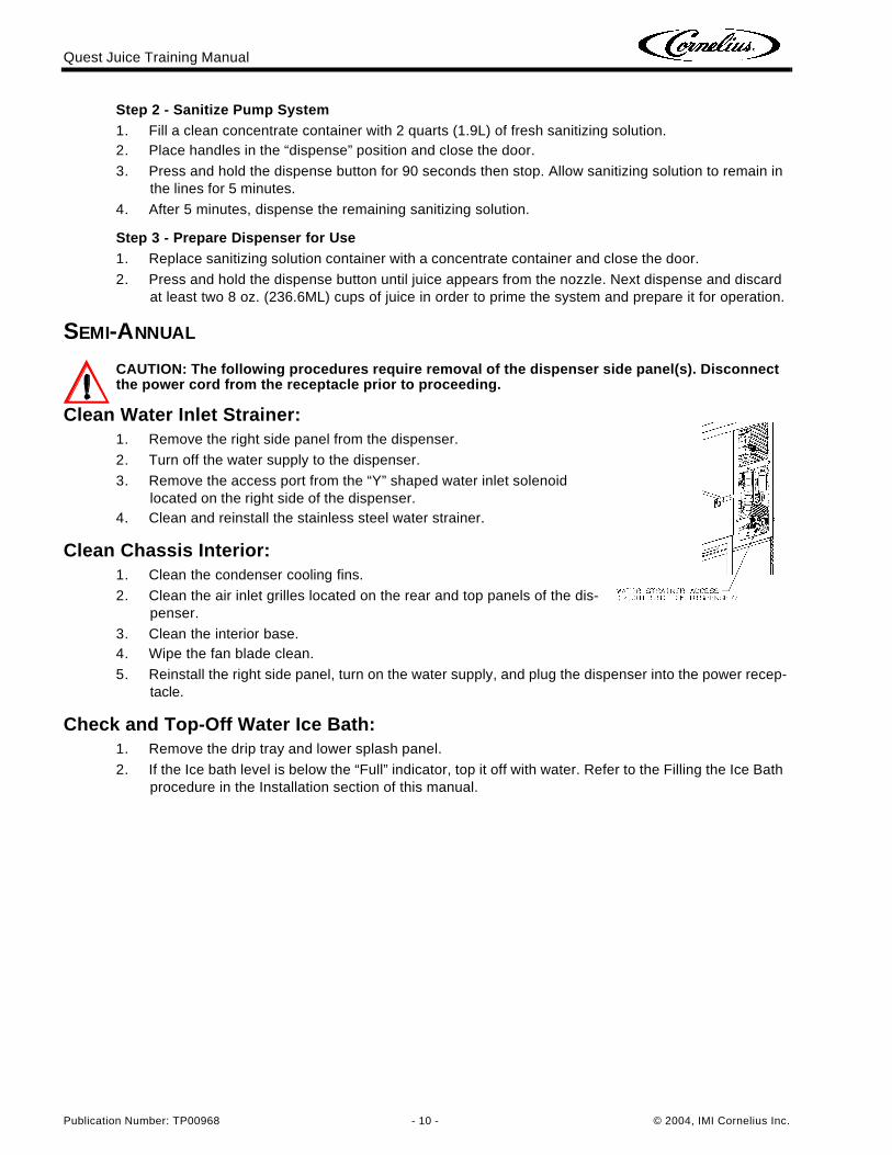
Clean Water Inlet Strainer:1. Remove the right side panel from the dispenser.
2. Turn off the water supply to the dispenser.
3. Remove the access port from the “Y” shaped water inlet solenoid located on the right side of the dispenser.
4. Clean and reinstall the stainless steel water strainer.
Clean Chassis Interior:1. Clean the condenser cooling fins.
2. Clean the air inlet grilles located on the rear and top panels of the dis-penser.
3. Clean the interior base.4. Wipe the fan blade clean.
5. Reinstall the right side panel, turn on the water supply, and plug the dispenser into the power recep-tacle.
Check and Top-Off Water Ice Bath:1. Remove the drip tray and lower splash panel.
2. If the Ice bath level is below the “Full” indicator, top it off with water. Refer to the Filling the Ice Bath procedure in the Installation section of this manual.
Quest Juice Training Manual
© 2004, IMI Cornelius Inc. - 11 - Publication Number: TP00968
ANNUALLY
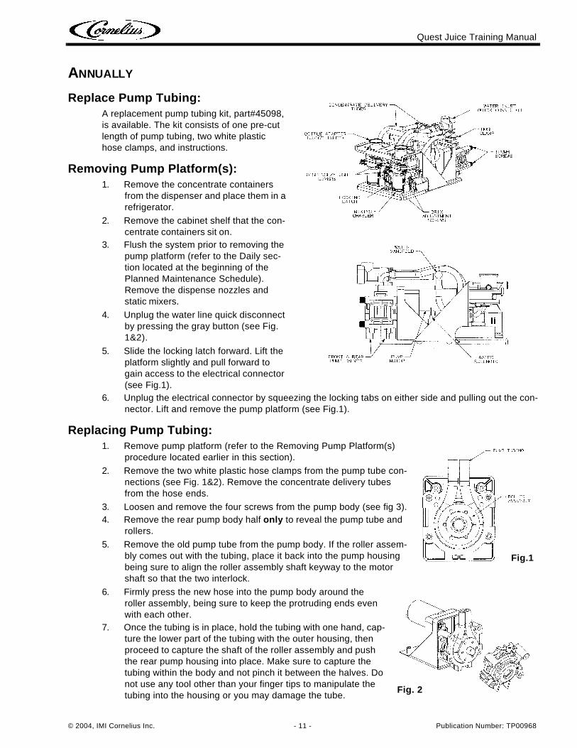
Replace Pump Tubing:A replacement pump tubing kit, part#45098, is available. The kit consists of one pre-cut length of pump tubing, two white plastic hose clamps, and instructions.
Removing Pump Platform(s):1. Remove the concentrate containers
from the dispenser and place them in a refrigerator.
2. Remove the cabinet shelf that the con-centrate containers sit on.
3. Flush the system prior to removing the pump platform (refer to the Daily sec-tion located at the beginning of the Planned Maintenance Schedule). Remove the dispense nozzles and static mixers.
4. Unplug the water line quick disconnect by pressing the gray button (see Fig. 1&2).
5. Slide the locking latch forward. Lift the platform slightly and pull forward to gain access to the electrical connector (see Fig.1).
6. Unplug the electrical connector by squeezing the locking tabs on either side and pulling out the con-nector. Lift and remove the pump platform (see Fig.1).
Replacing Pump Tubing:1. Remove pump platform (refer to the Removing Pump Platform(s)
procedure located earlier in this section).
2. Remove the two white plastic hose clamps from the pump tube con-nections (see Fig. 1&2). Remove the concentrate delivery tubes from the hose ends.
3. Loosen and remove the four screws from the pump body (see fig 3).4. Remove the rear pump body half only to reveal the pump tube and
rollers.
5. Remove the old pump tube from the pump body. If the roller assem-bly comes out with the tubing, place it back into the pump housing being sure to align the roller assembly shaft keyway to the motor shaft so that the two interlock.
6. Firmly press the new hose into the pump body around the roller assembly, being sure to keep the protruding ends even with each other.
7. Once the tubing is in place, hold the tubing with one hand, cap-ture the lower part of the tubing with the outer housing, then proceed to capture the shaft of the roller assembly and push the rear pump housing into place. Make sure to capture the tubing within the body and not pinch it between the halves. Do not use any tool other than your finger tips to manipulate the tubing into the housing or you may damage the tube.
Fig.1
Fig. 2
Quest Juice Training Manual
Publication Number: TP00968 - 12 - © 2004, IMI Cornelius Inc.
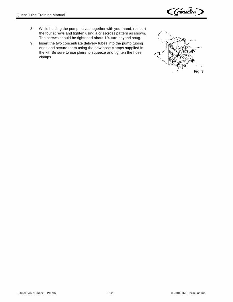
8. While holding the pump halves together with your hand, reinsert the four screws and tighten using a crisscross pattern as shown. The screws should be tightened about 1/4 turn beyond snug.
9. Insert the two concentrate delivery tubes into the pump tubing ends and secure them using the new hose clamps supplied in the kit. Be sure to use pliers to squeeze and tighten the hose clamps.
Fig. 3
Quest Juice Training Manual
© 2004, IMI Cornelius Inc. - 13 - Publication Number: TP00968
MECHANICAL SECTIONREMOVAL OF MERCHANDISER
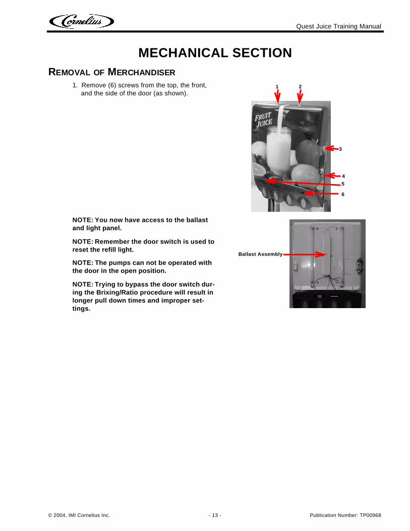
1. Remove (6) screws from the top, the front, and the side of the door (as shown).
NOTE: You now have access to the ballast and light panel.
NOTE: Remember the door switch is used to reset the refill light.
NOTE: The pumps can not be operated with the door in the open position.
NOTE: Trying to bypass the door switch dur-ing the Brixing/Ratio procedure will result in longer pull down times and improper set-tings.
3
4
6
5
1 2
Ballast Assembly
Quest Juice Training Manual
Publication Number: TP00968 - 14 - © 2004, IMI Cornelius Inc.
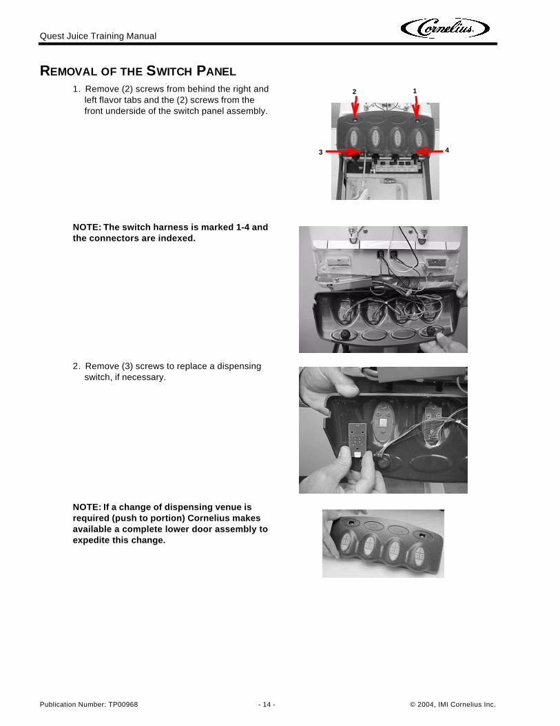
REMOVAL OF THE SWITCH PANEL
1. Remove (2) screws from behind the right and left flavor tabs and the (2) screws from the front underside of the switch panel assembly.
NOTE: The switch harness is marked 1-4 and the connectors are indexed.
2. Remove (3) screws to replace a dispensing switch, if necessary.
NOTE: If a change of dispensing venue is required (push to portion) Cornelius makes available a complete lower door assembly to expedite this change.
3 4
12
Quest Juice Training Manual
© 2004, IMI Cornelius Inc. - 15 - Publication Number: TP00968
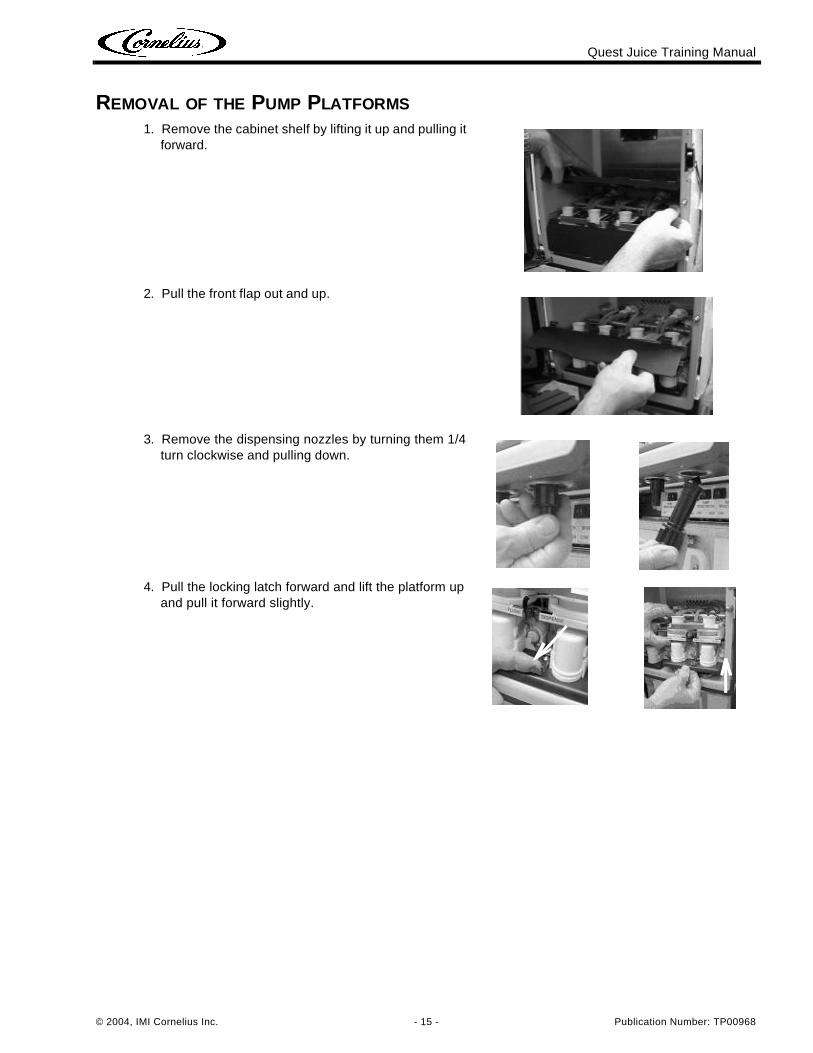
REMOVAL OF THE PUMP PLATFORMS
1. Remove the cabinet shelf by lifting it up and pulling it forward.
2. Pull the front flap out and up.
3. Remove the dispensing nozzles by turning them 1/4 turn clockwise and pulling down.
4. Pull the locking latch forward and lift the platform up and pull it forward slightly.
Quest Juice Training Manual
Publication Number: TP00968 - 16 - © 2004, IMI Cornelius Inc.
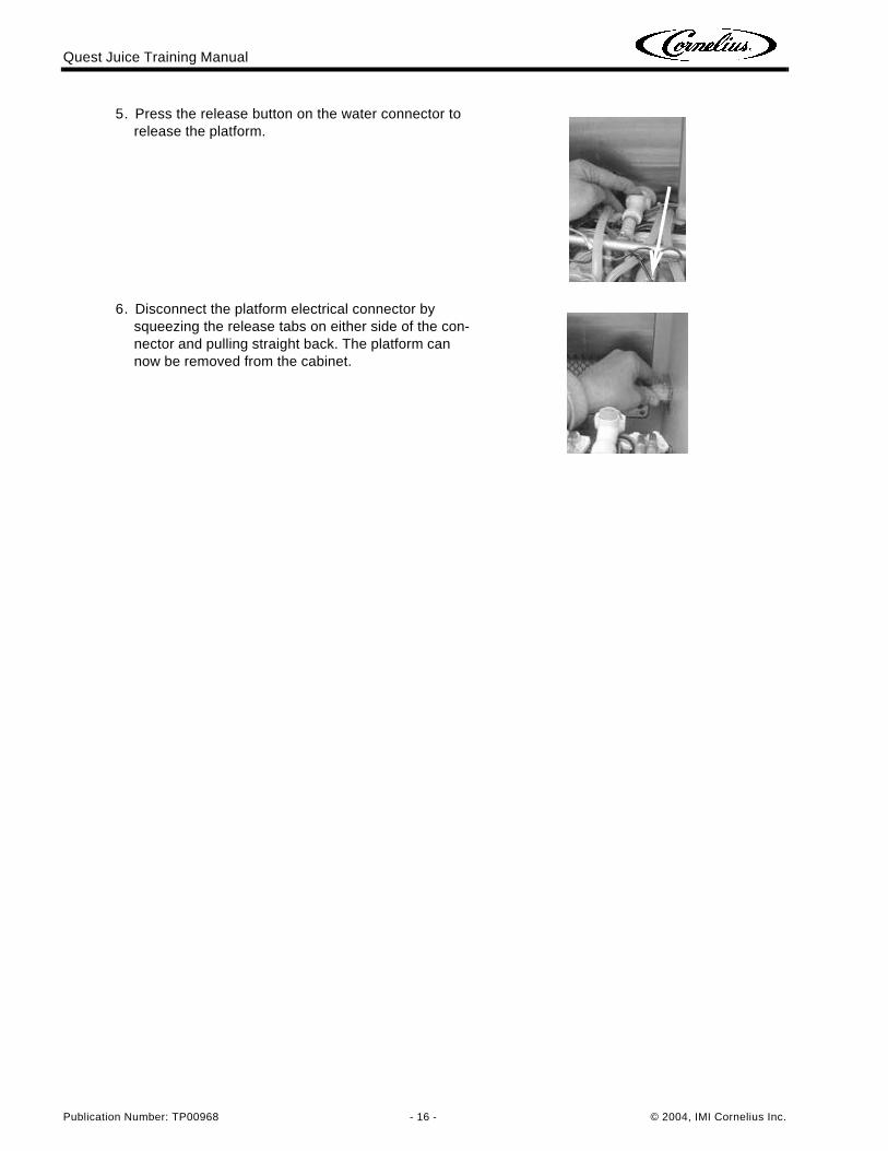
5. Press the release button on the water connector to release the platform.
6. Disconnect the platform electrical connector by squeezing the release tabs on either side of the con-nector and pulling straight back. The platform can now be removed from the cabinet.
Quest Juice Training Manual
© 2004, IMI Cornelius Inc. - 17 - Publication Number: TP00968
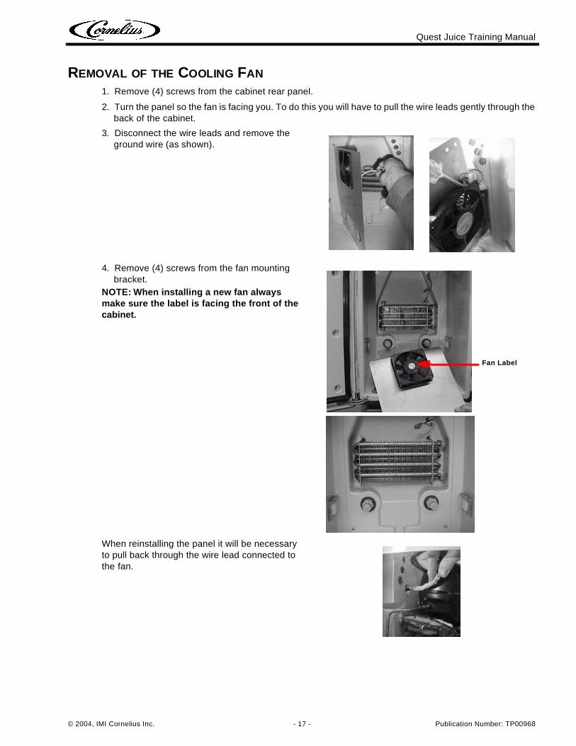
REMOVAL OF THE COOLING FAN
1. Remove (4) screws from the cabinet rear panel.
2. Turn the panel so the fan is facing you. To do this you will have to pull the wire leads gently through the back of the cabinet.
3. Disconnect the wire leads and remove the ground wire (as shown).
4. Remove (4) screws from the fan mounting bracket.
NOTE: When installing a new fan always make sure the label is facing the front of the cabinet.
When reinstalling the panel it will be necessary to pull back through the wire lead connected to the fan.
Fan Label
Quest Juice Training Manual
Publication Number: TP00968 - 18 - © 2004, IMI Cornelius Inc.
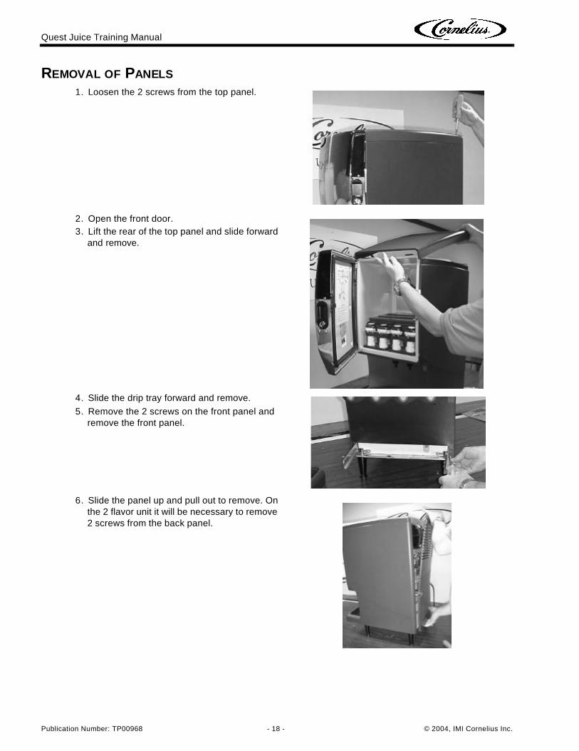
REMOVAL OF PANELS
1. Loosen the 2 screws from the top panel.
2. Open the front door.3. Lift the rear of the top panel and slide forward
and remove.
4. Slide the drip tray forward and remove.
5. Remove the 2 screws on the front panel and remove the front panel.
6. Slide the panel up and pull out to remove. On the 2 flavor unit it will be necessary to remove 2 screws from the back panel.
Quest Juice Training Manual
© 2004, IMI Cornelius Inc. - 19 - Publication Number: TP00968
REMOVAL OF ELECTRICAL BOX
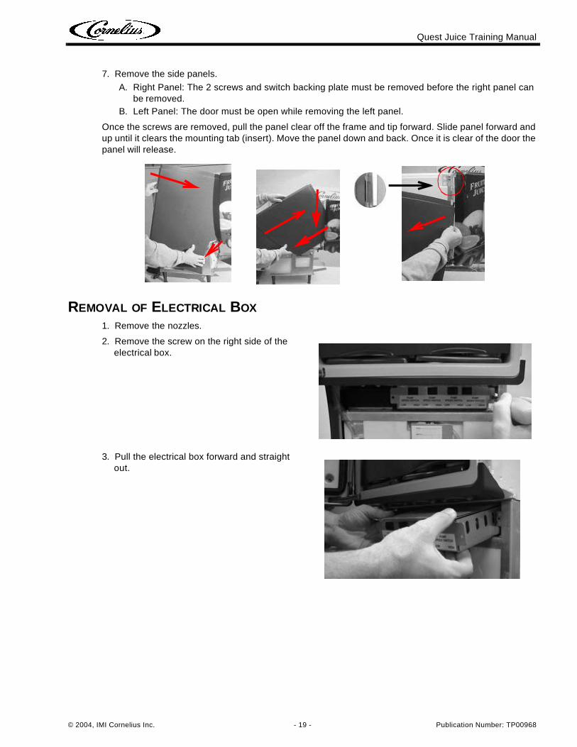
7. Remove the side panels.
A. Right Panel: The 2 screws and switch backing plate must be removed before the right panel can be removed.
B. Left Panel: The door must be open while removing the left panel.
Once the screws are removed, pull the panel clear off the frame and tip forward. Slide panel forward and up until it clears the mounting tab (insert). Move the panel down and back. Once it is clear of the door the panel will release.
1. Remove the nozzles.
2. Remove the screw on the right side of the electrical box.
3. Pull the electrical box forward and straight out.
Quest Juice Training Manual
Publication Number: TP00968 - 20 - © 2004, IMI Cornelius Inc.
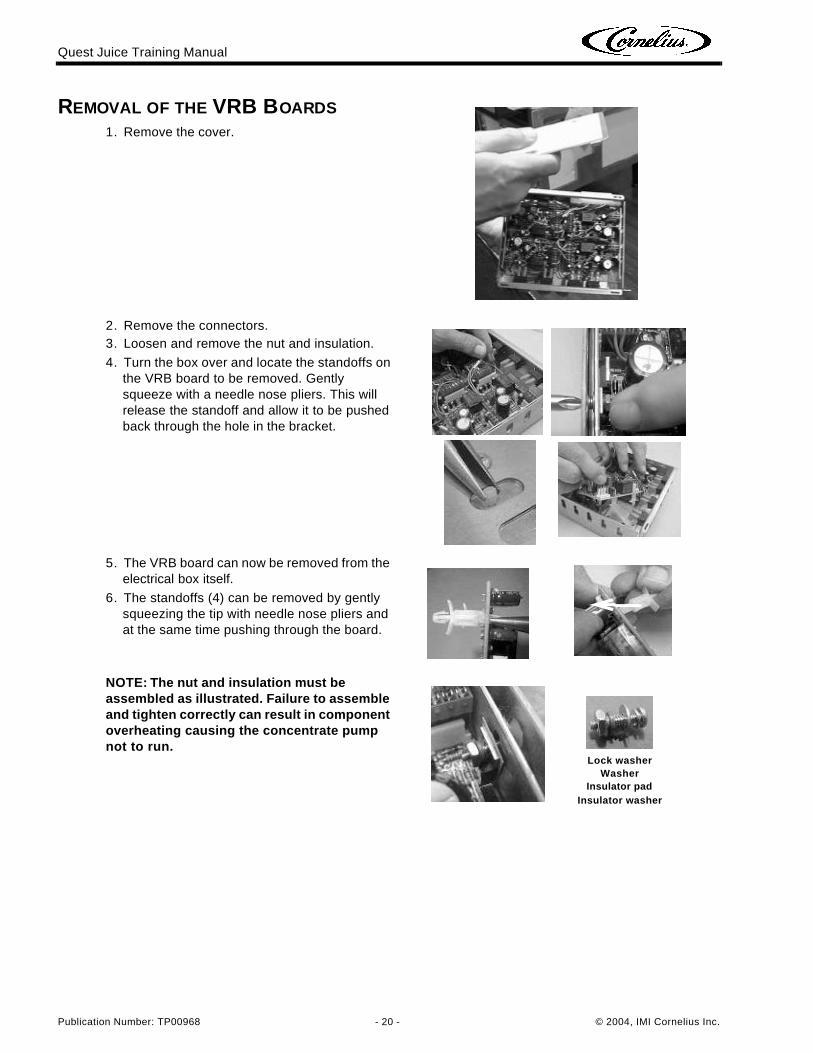
REMOVAL OF THE VRB BOARDS1. Remove the cover.
2. Remove the connectors.3. Loosen and remove the nut and insulation.
4. Turn the box over and locate the standoffs on the VRB board to be removed. Gently squeeze with a needle nose pliers. This will release the standoff and allow it to be pushed back through the hole in the bracket.
5. The VRB board can now be removed from the electrical box itself.
6. The standoffs (4) can be removed by gently squeezing the tip with needle nose pliers and at the same time pushing through the board.
NOTE: The nut and insulation must be assembled as illustrated. Failure to assemble and tighten correctly can result in component overheating causing the concentrate pump not to run.
Lock washerWasher
Insulator padInsulator washer
Quest Juice Training Manual
© 2004, IMI Cornelius Inc. - 21 - Publication Number: TP00968
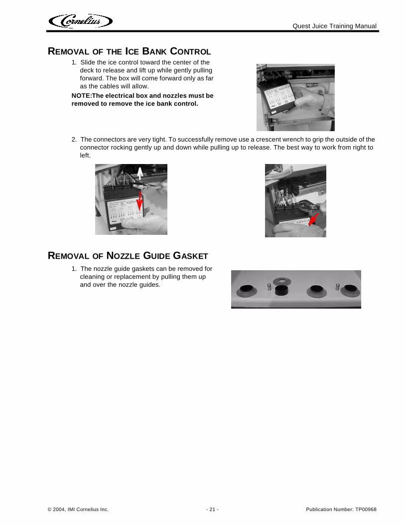
REMOVAL OF THE ICE BANK CONTROL
REMOVAL OF NOZZLE GUIDE GASKET
1. Slide the ice control toward the center of the deck to release and lift up while gently pulling forward. The box will come forward only as far as the cables will allow.
NOTE:The electrical box and nozzles must be removed to remove the ice bank control.
2. The connectors are very tight. To successfully remove use a crescent wrench to grip the outside of the connector rocking gently up and down while pulling up to release. The best way to work from right to left.
1. The nozzle guide gaskets can be removed for cleaning or replacement by pulling them up and over the nozzle guides.
Quest Juice Training Manual
Publication Number: TP00968 - 22 - © 2004, IMI Cornelius Inc.
REMOVAL OF THE COOLING CABINET
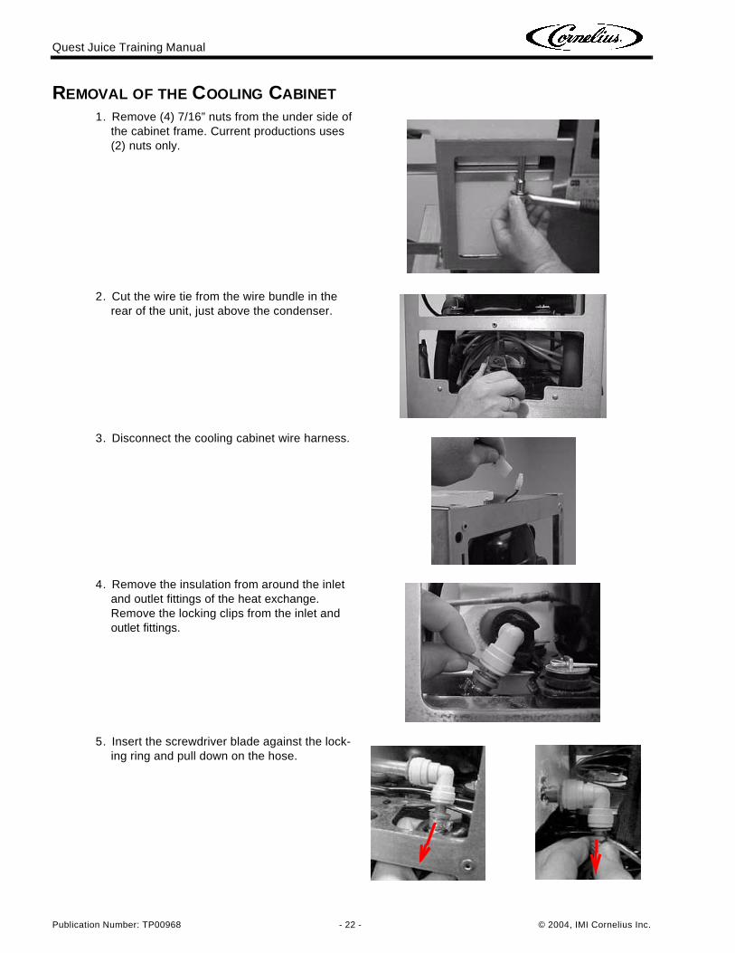
1. Remove (4) 7/16” nuts from the under side of the cabinet frame. Current productions uses (2) nuts only.
2. Cut the wire tie from the wire bundle in the rear of the unit, just above the condenser.
3. Disconnect the cooling cabinet wire harness.
4. Remove the insulation from around the inlet and outlet fittings of the heat exchange. Remove the locking clips from the inlet and outlet fittings.
5. Insert the screwdriver blade against the lock-ing ring and pull down on the hose.
Quest Juice Training Manual
© 2004, IMI Cornelius Inc. - 23 - Publication Number: TP00968
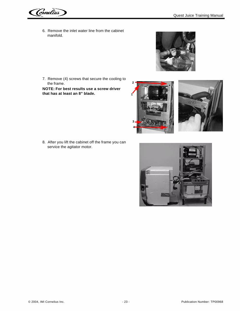
6. Remove the inlet water line from the cabinet manifold.
7. Remove (4) screws that secure the cooling to the frame.
NOTE: For best results use a screw driver that has at least an 8” blade.
8. After you lift the cabinet off the frame you can service the agitator motor.
2
1
3
4
Quest Juice Training Manual
Publication Number: TP00968 - 24 - © 2004, IMI Cornelius Inc.
REMOVAL OF THE AGITATOR MOTOR
REMOVAL OF THE REFRIGERATION CHASSIS
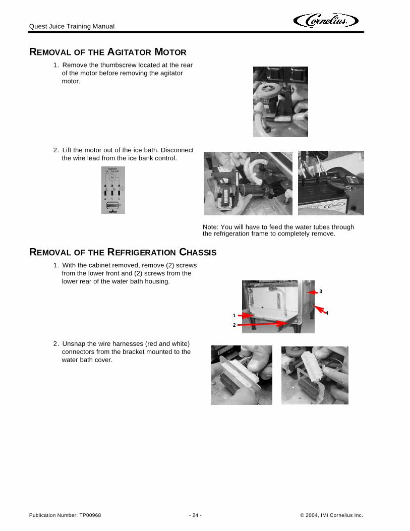
1. Remove the thumbscrew located at the rear of the motor before removing the agitator motor.
2. Lift the motor out of the ice bath. Disconnect the wire lead from the ice bank control.
Note: You will have to feed the water tubes through the refrigeration frame to completely remove.
1. With the cabinet removed, remove (2) screws from the lower front and (2) screws from the lower rear of the water bath housing.
2. Unsnap the wire harnesses (red and white) connectors from the bracket mounted to the water bath cover.
2
13
41
Quest Juice Training Manual
© 2004, IMI Cornelius Inc. - 25 - Publication Number: TP00968
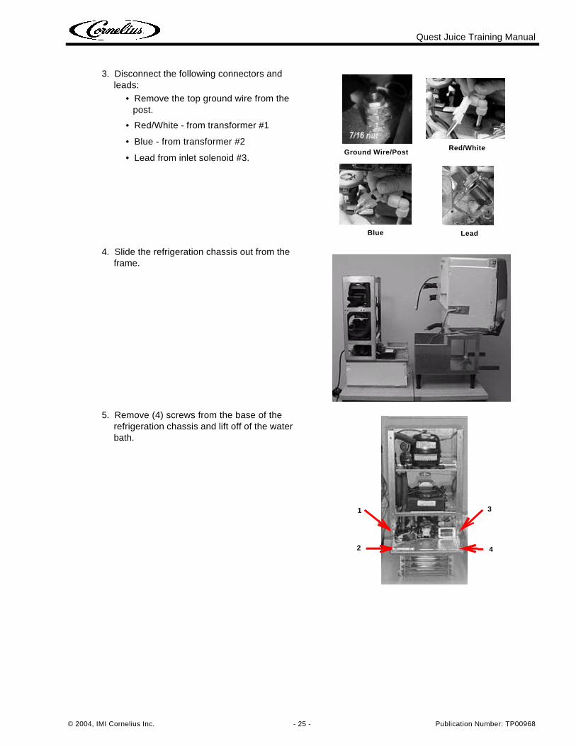
3. Disconnect the following connectors and leads:
• Remove the top ground wire from the post.
• Red/White - from transformer #1
• Blue - from transformer #2
• Lead from inlet solenoid #3.
4. Slide the refrigeration chassis out from the frame.
5. Remove (4) screws from the base of the refrigeration chassis and lift off of the water bath.
Red/White
Blue Lead
Ground Wire/Post
2
1
4
3
Quest Juice Training Manual
Publication Number: TP00968 - 26 - © 2004, IMI Cornelius Inc.
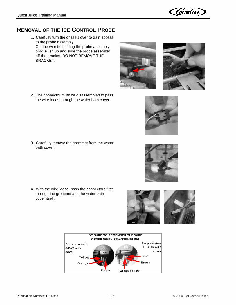
REMOVAL OF THE ICE CONTROL PROBE
1. Carefully turn the chassis over to gain access to the probe assembly.Cut the wire tie holding the probe assembly only. Push up and slide the probe assembly off the bracket. DO NOT REMOVE THE BRACKET.
2. The connector must be disassembled to pass the wire leads through the water bath cover.
3. Carefully remove the grommet from the water bath cover.
4. With the wire loose, pass the connectors first through the grommet and the water bath cover itself.
BE SURE TO REMEMBER THE WIRE ORDER WHEN RE-ASSEMBLING
Yellow
Orange
Purple
Blue
Brown
Green/Yellow
Current version GRAY wire cover
Early versionBLACK wire
cover
Quest Juice Training Manual
© 2004, IMI Cornelius Inc. - 27 - Publication Number: TP00968
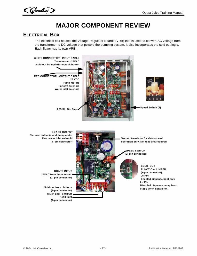
MAJOR COMPONENT REVIEWELECTRICAL BOX
The electrical box houses the Voltage Regulator Boards (VRB) that is used to convert AC voltage from the transformer to DC voltage that powers the pumping system. It also incorporates the sold out logic. Each flavor has its own VRB.
6.25 Slo Blo Fuse
WHITE CONNECTOR - INPUT CABLETransformer- 26VAC
Sold out from platform push button
RED CONNECTOR - OUTPUT CABLE28 VDC
Pump motorsPlatform solenoid
Water inlet solenoid
Speed Switch (4)
Pump4
Pump3
Pump2
Pump1
Pump1 2 3 4
SOLD–OUTFUNCTION-JUMPER(3-pin connector)J5 PINEnabled dispense light only
LK PINDisabled dispense pump head stops when light is on.
BOARD INPUT26VAC from Transformer
(2- pin connector)
Sold-out from platform(2-pin connector)
Touch pad –SWITCHRefill light
(2-pin connector)
SPEED SWITCH(2 -pin connector)
Second transistor for slow -speed operation only. No heat sink required
BOARD OUTPUTPlatform solenoid and pump motor
Rear water inlet solenoid(4 -pin connector)
VRBBoard
Quest Juice Training Manual
Publication Number: TP00968 - 28 - © 2004, IMI Cornelius Inc.
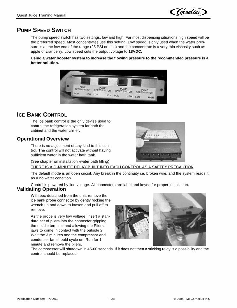
PUMP SPEED SWITCHThe pump speed switch has two settings, low and high. For most dispensing situations high speed will be the preferred speed. Most concentrates use this setting. Low speed is only used when the water pres-sure is at the low end of the range (25 PSI or less) and the concentrate is a very thin viscosity such as apple or cranberry. Low speed cuts the output voltage to 18VDC.
Using a water booster system to increase the flowing pressure to the recommended pressure is a better solution.
ICE BANK CONTROLThe ice bank control is the only devise used to control the refrigeration system for both the cabinet and the water chiller.
Operational OverviewThere is no adjustment of any kind to this con-trol. The control will not activate without having sufficient water in the water bath tank.
(See chapter on installation -water bath filling)
THERE IS A 3 -MINUTE DELAY BUILT INTO EACH CONTROL AS A SAFTEY PRECAUTION.
The default mode is an open circuit. Any break in the continuity i.e. broken wire, and the system reads it as a no water condition.
Control is powered by line voltage. All connectors are label and keyed for proper installation.Validating Operation
With box detached from the unit, remove the ice bank probe connector by gently rocking the wrench up and down to loosen and pull off to remove.
As the probe is very low voltage, insert a stan-dard set of pliers into the connector gripping the middle terminal and allowing the Pliers’ jaws to come in contact with the outside 2. Wait the 3 minutes and the compressor and condenser fan should cycle on. Run for 1 minute and remove the pliers. The compressor will shutdown in 45-60 seconds. If it does not then a sticking relay is a possibility and the control should be replaced.
Quest Juice Training Manual
© 2004, IMI Cornelius Inc. - 29 - Publication Number: TP00968
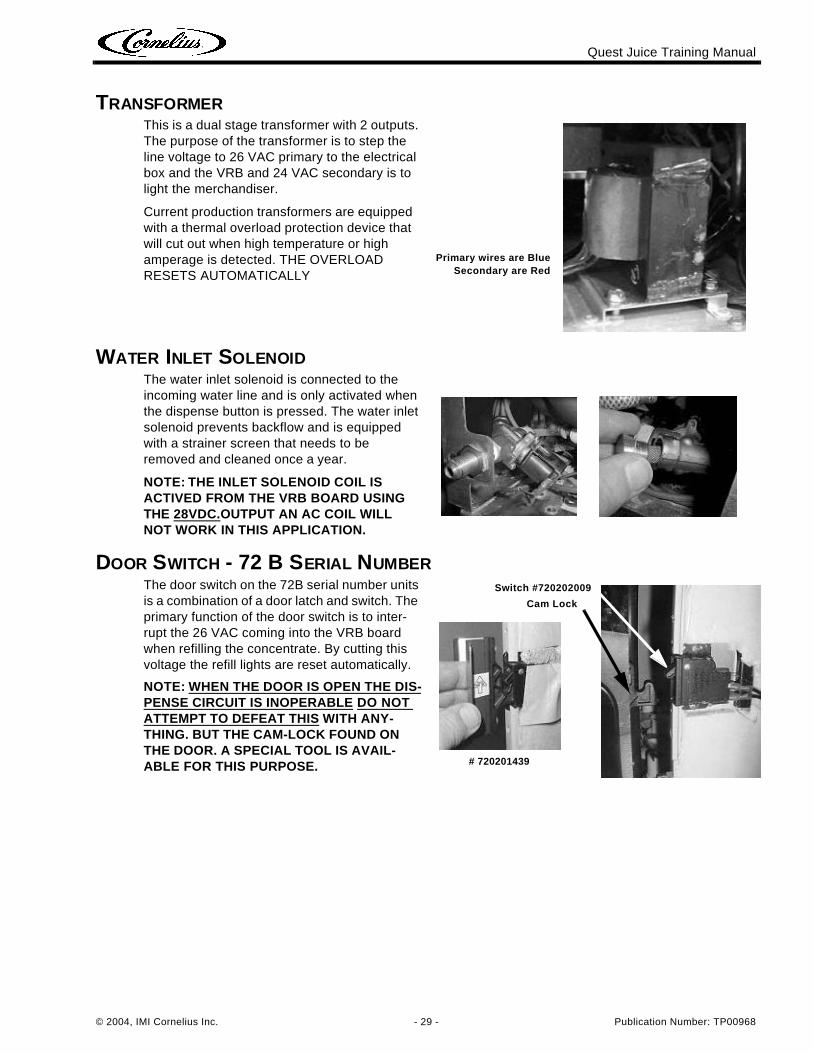
TRANSFORMER
WATER INLET SOLENOID
DOOR SWITCH - 72 B SERIAL NUMBER
This is a dual stage transformer with 2 outputs. The purpose of the transformer is to step the line voltage to 26 VAC primary to the electrical box and the VRB and 24 VAC secondary is to light the merchandiser.
Current production transformers are equipped with a thermal overload protection device that will cut out when high temperature or high amperage is detected. THE OVERLOAD RESETS AUTOMATICALLY
The water inlet solenoid is connected to the incoming water line and is only activated when the dispense button is pressed. The water inlet solenoid prevents backflow and is equipped with a strainer screen that needs to be removed and cleaned once a year.
NOTE: THE INLET SOLENOID COIL IS ACTIVED FROM THE VRB BOARD USING THE 28VDC.OUTPUT AN AC COIL WILL NOT WORK IN THIS APPLICATION.
The door switch on the 72B serial number units is a combination of a door latch and switch. The primary function of the door switch is to inter-rupt the 26 VAC coming into the VRB board when refilling the concentrate. By cutting this voltage the refill lights are reset automatically.
NOTE: WHEN THE DOOR IS OPEN THE DIS-PENSE CIRCUIT IS INOPERABLE DO NOT ATTEMPT TO DEFEAT THIS WITH ANY-THING. BUT THE CAM-LOCK FOUND ON THE DOOR. A SPECIAL TOOL IS AVAIL-ABLE FOR THIS PURPOSE.
Primary wires are BlueSecondary are Red
# 720201439
Cam Lock
Switch #720202009
Quest Juice Training Manual
Publication Number: TP00968 - 30 - © 2004, IMI Cornelius Inc.
DOOR SWITCH - 72 E SERIAL NUMBER
PLATFORM COMPONENTS
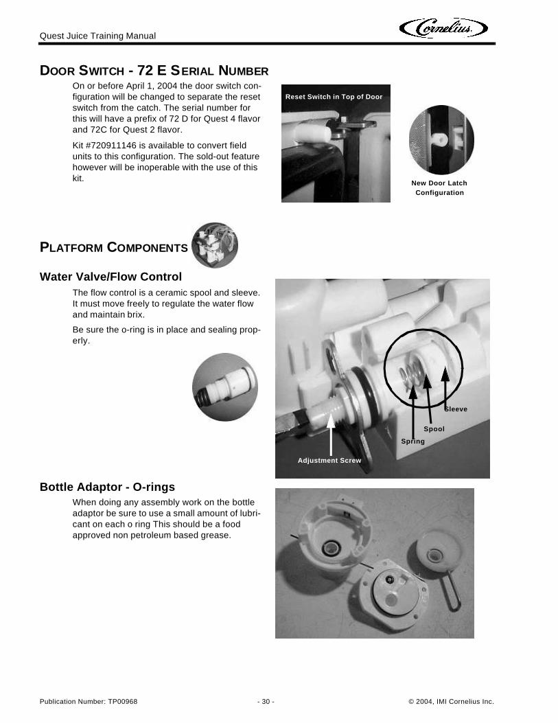
On or before April 1, 2004 the door switch con-figuration will be changed to separate the reset switch from the catch. The serial number for this will have a prefix of 72 D for Quest 4 flavor and 72C for Quest 2 flavor.
Kit #720911146 is available to convert field units to this configuration. The sold-out feature however will be inoperable with the use of this kit.
Water Valve/Flow ControlThe flow control is a ceramic spool and sleeve. It must move freely to regulate the water flow and maintain brix.
Be sure the o-ring is in place and sealing prop-erly.
Bottle Adaptor - O-ringsWhen doing any assembly work on the bottle adaptor be sure to use a small amount of lubri-cant on each o ring This should be a food approved non petroleum based grease.
Reset Switch in Top of Door
New Door Latch Configuration
Adjustment Screw
Spring
Sleeve
Spool
Quest Juice Training Manual
© 2004, IMI Cornelius Inc. - 31 - Publication Number: TP00968
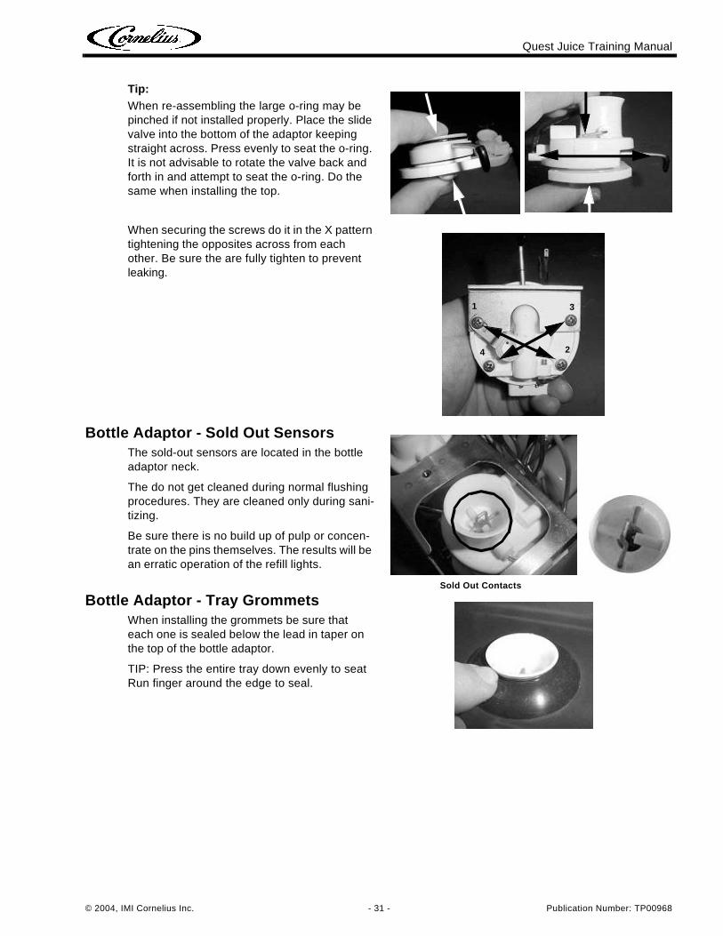
Tip:When re-assembling the large o-ring may be pinched if not installed properly. Place the slide valve into the bottom of the adaptor keeping straight across. Press evenly to seat the o-ring. It is not advisable to rotate the valve back and forth in and attempt to seat the o-ring. Do the same when installing the top.
When securing the screws do it in the X pattern tightening the opposites across from each other. Be sure the are fully tighten to prevent leaking.
Bottle Adaptor - Sold Out SensorsThe sold-out sensors are located in the bottle adaptor neck.
The do not get cleaned during normal flushing procedures. They are cleaned only during sani-tizing.
Be sure there is no build up of pulp or concen-trate on the pins themselves. The results will be an erratic operation of the refill lights.
Bottle Adaptor - Tray GrommetsWhen installing the grommets be sure that each one is sealed below the lead in taper on the top of the bottle adaptor.
TIP: Press the entire tray down evenly to seat Run finger around the edge to seal.
1 3
24
Sold Out Contacts
Quest Juice Training Manual
Publication Number: TP00968 - 32 - © 2004, IMI Cornelius Inc.
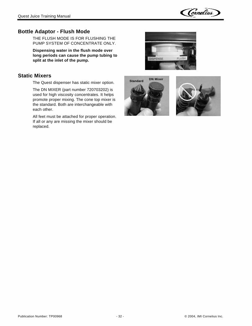
Bottle Adaptor - Flush ModeTHE FLUSH MODE IS FOR FLUSHING THE PUMP SYSTEM OF CONCENTRATE ONLY.
Dispensing water in the flush mode over long periods can cause the pump tubing to split at the inlet of the pump.
Static MixersThe Quest dispenser has static mixer option.
The DN MIXER (part number 720703202) is used for high viscosity concentrates. It helps promote proper mixing. The cone top mixer is the standard. Both are interchangeable with each other.
All feet must be attached for proper operation. If all or any are missing the mixer should be replaced.
StandardDN Mixer
Quest Juice Training Manual
© 2004, IMI Cornelius Inc. - 33 - Publication Number: TP00968
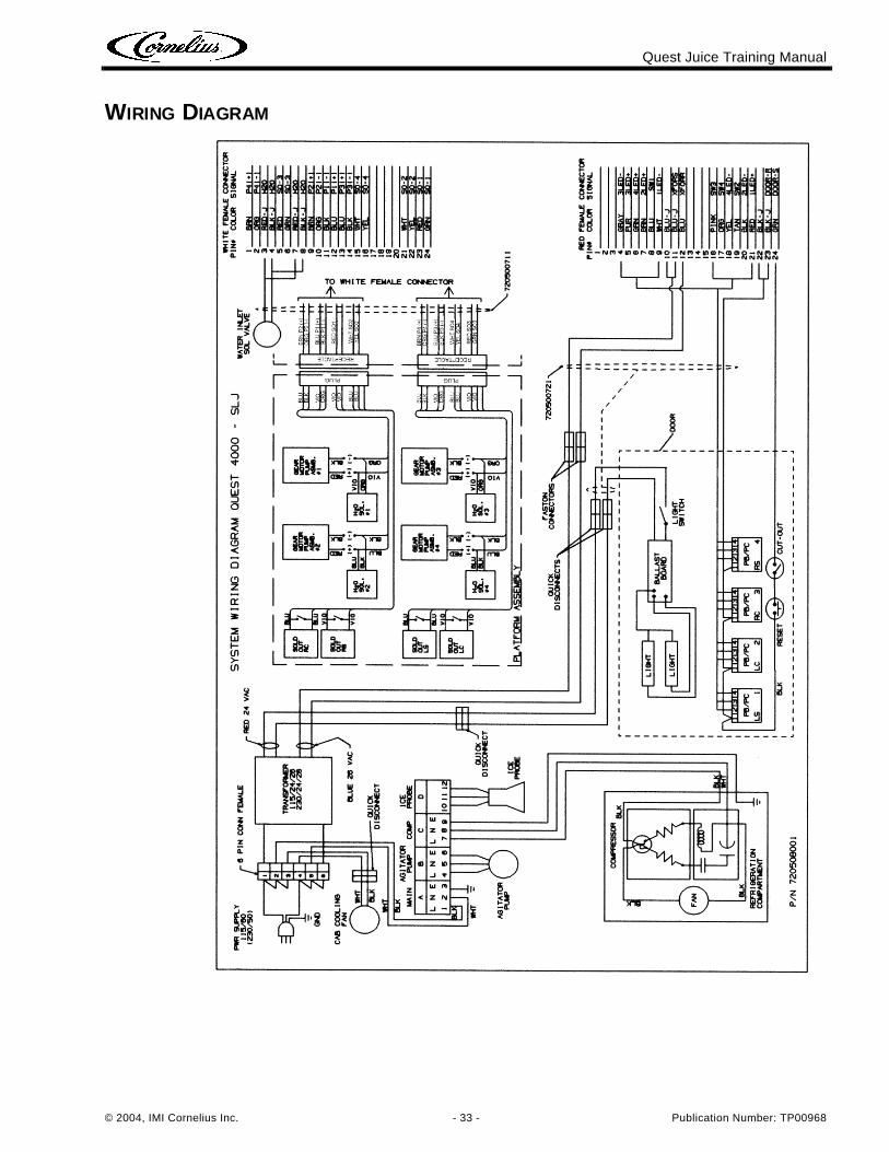
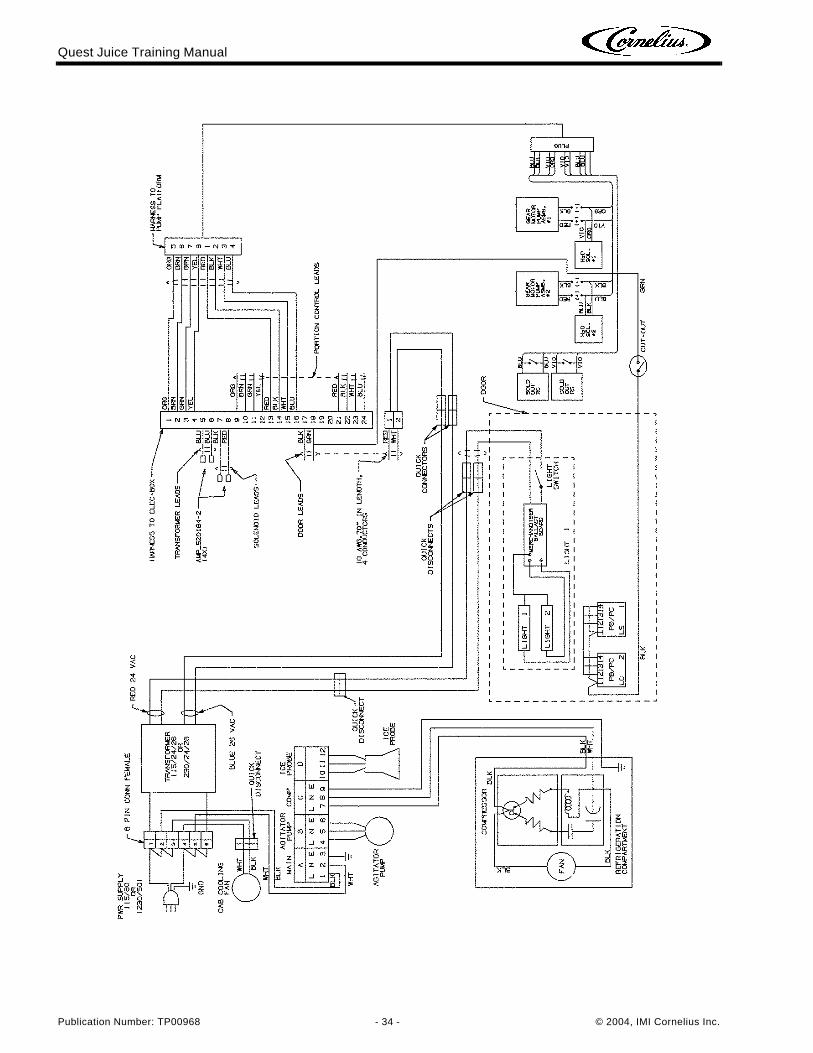
WIRING DIAGRAM
Quest Juice Training Manual
Publication Number: TP00968 - 34 - © 2004, IMI Cornelius Inc.
Quest Juice Training Manual
© 2004, IMI Cornelius Inc. - 35 - Publication Number: TP00968
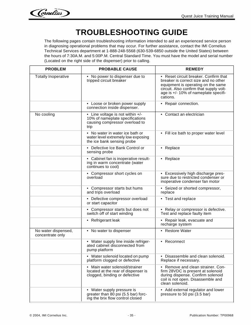
TROUBLESHOOTING GUIDEThe following pages contain troubleshooting information intended to aid an experienced service person in diagnosing operational problems that may occur. For further assistance, contact the IMI Cornelius Technical Services department at 1-888-248-5568 (630-539-6850 outside the United States) between the hours of 7:30A.M. and 5:00P.M. Central Standard Time. You must have the model and serial number (Located on the right side of the dispenser) prior to calling.
PROBLEM PROBABLE CAUSE REMEDY
Totally Inoperative • No power to dispenser due to tripped circuit breaker
• Reset circuit breaker. Confirm that breaker is correct size and no other equipment is operating on the same circuit. Also confirm that supply volt-age is +/- 10% of nameplate specifi-cations.
• Loose or broken power supply connection inside dispenser.
• Repair connection.
No cooling • Line voltage is not within +/- 10% of nameplate specifications causing compressor overload to trip
• Contact an electrician
• No water in water ice bath or water level extremely low exposing the ice bank sensing probe
• Fill ice bath to proper water level
• Defective Ice Bank Control or sensing probe
• Replace
• Cabinet fan is inoperative result-ing in warm concentrate (water continues to cool)
• Replace
• Compressor short cycles on overload
• Excessively high discharge pres-sure due to restricted condenser or inoperative condenser fan motor
• Compressor starts but hums and trips overload
• Seized or shorted compressor, replace
• Defective compressor overload or start capacitor
• Test and replace
• Compressor starts but does not switch off of start winding
• Relay or compressor is defective. Test and replace faulty item
• Refrigerant leak • Repair leak, evacuate and recharge system
No water dispensed, concentrate only
• No water to dispenser • Restore Water
• Water supply line inside refriger-ated cabinet disconnected from pump platform
• Reconnect
• Water solenoid located on pump platform clogged or defective
• Disassemble and clean solenoid. Replace if necessary.
• Main water solenoid/strainer located at the rear of dispenser is clogged, binding or defective
• Remove and clean strainer. Con-firm 28VDC is present at solenoid during dispense. Confirm solenoid coil is not open. Disassemble and clean solenoid.
• Water supply pressure is greater than 80 psi (5.5 bar) forc-ing the brix flow control closed
• Add external regulator and lower pressure to 50 psi (3.5 bar)
Quest Juice Training Manual
Publication Number: TP00968 - 36 - © 2004, IMI Cornelius Inc.
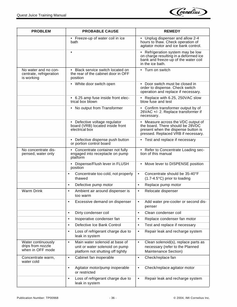
• Freeze-up of water coil in ice bath
• Unplug dispenser and allow 2-4 hours to thaw. Check operation of agitator motor and ice bank control.
• • Refrigeration system may be low on charge resulting in a deformed ice bank and freeze-up of the water coil in the ice bath.
No water and no con-centrate, refrigeration is working
• Black service switch located on the rear of the cabinet door in OFF position
• Turn on switch
• White door switch open • Door switch must be closed in order to dispense. Check switch operation and replace if necessary.
• 6.25 amp fuse inside front elec-trical box blown
• Replace with 6.25, 250VAC slow blow fuse and test
• No output from Transformer • Confirm transformer output by of 26VAC +/- 2. Replace transformer if necessary.
• Defective voltage regulator board (VRB) located inside front electrical box
• Measure across the VDC output of the board. There should be 28VDC present when the dispense button is pressed. Replaced VRB if necessary.
• Defective dispense push button or portion control board
• Test and replace if necessary
No concentrate dis-pensed, water only
• Concentrate container not fully engaged into receptacle on pump platform
• Refer to Concentrate Loading sec-tion of this manual
• Dispense/Flush lever in FLUSH position
• Move lever to DISPENSE position
• Concentrate too cold, not properly thawed
• Concentrate should be 35-40°F (1.7-4.5°C) prior to loading
• Defective pump motor • Replace pump motor
Warm Drink • Ambient air around dispenser is too warm
• Relocate dispenser
• Excessive demand on dispenser • Add water pre-cooler or second dis-penser
• Dirty condenser coil • Clean condenser coil
• Inoperative condenser fan • Replace condenser fan motor
• Defective Ice Bank Control • Test and replace if necessary
• Loss of refrigerant charge due to leak in system
• Repair leak and recharge system
Water continuously drips from nozzle when in OFF mode
• Main water solenoid at base of unit or water solenoid on pump platform not shutting off tightly
• Clean solenoid(s), replace parts as necessary (refer to the Planned Maintenance Section)
Concentrate warm, water cold
• Cabinet fan inoperable • Check/replace fan
• Agitator motor/pump inoperable or restricted
• Check/replace agitator motor
• Loss of refrigerant charge due to leak in system
• Repair leak and recharge system
PROBLEM PROBABLE CAUSE REMEDY
Quest Juice Training Manual
© 2004, IMI Cornelius Inc. - 37 - Publication Number: TP00968
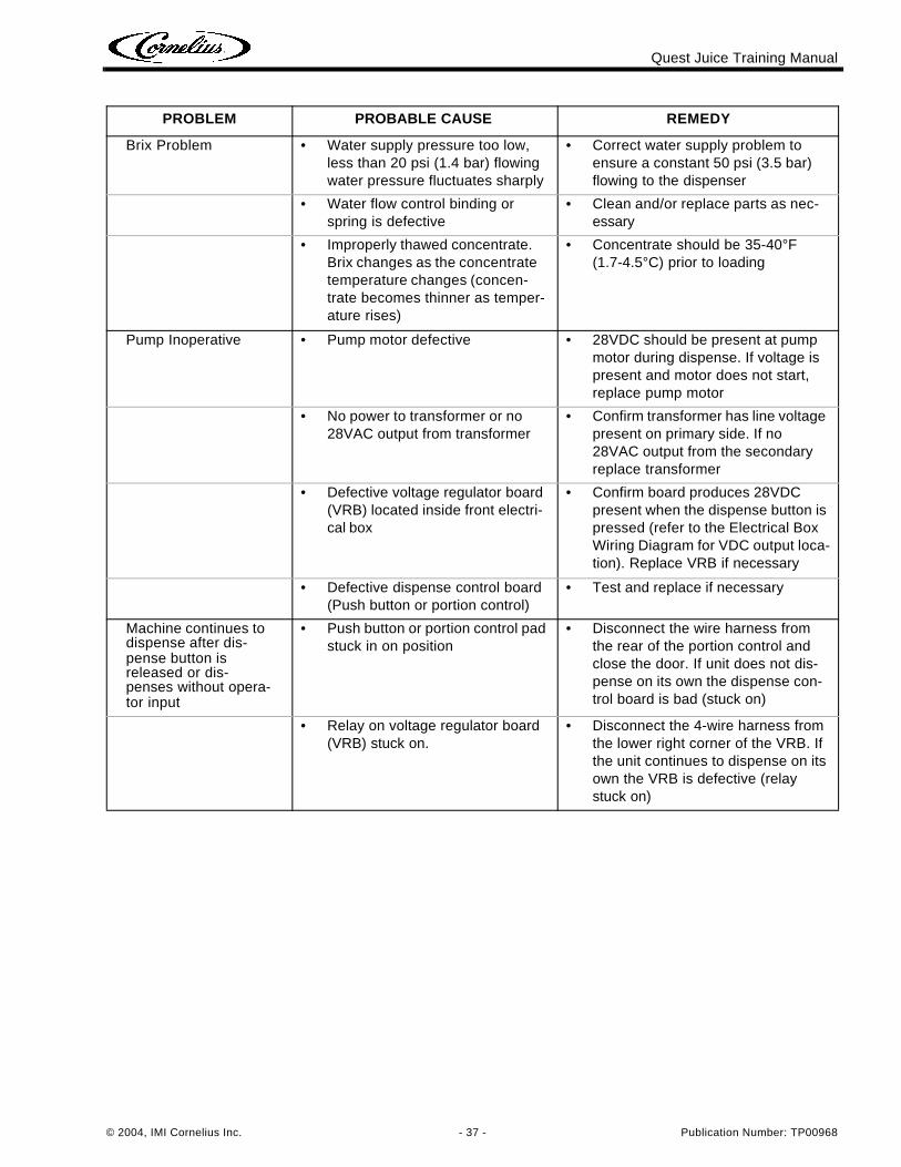
Brix Problem • Water supply pressure too low, less than 20 psi (1.4 bar) flowing water pressure fluctuates sharply
• Correct water supply problem to ensure a constant 50 psi (3.5 bar) flowing to the dispenser
• Water flow control binding or spring is defective
• Clean and/or replace parts as nec-essary
• Improperly thawed concentrate. Brix changes as the concentrate temperature changes (concen-trate becomes thinner as temper-ature rises)
• Concentrate should be 35-40°F (1.7-4.5°C) prior to loading
Pump Inoperative • Pump motor defective • 28VDC should be present at pump motor during dispense. If voltage is present and motor does not start, replace pump motor
• No power to transformer or no 28VAC output from transformer
• Confirm transformer has line voltage present on primary side. If no 28VAC output from the secondary replace transformer
• Defective voltage regulator board (VRB) located inside front electri-cal box
• Confirm board produces 28VDC present when the dispense button is pressed (refer to the Electrical Box Wiring Diagram for VDC output loca-tion). Replace VRB if necessary
• Defective dispense control board (Push button or portion control)
• Test and replace if necessary
Machine continues to dispense after dis-pense button is released or dis-penses without opera-tor input
• Push button or portion control pad stuck in on position
• Disconnect the wire harness from the rear of the portion control and close the door. If unit does not dis-pense on its own the dispense con-trol board is bad (stuck on)
• Relay on voltage regulator board (VRB) stuck on.
• Disconnect the 4-wire harness from the lower right corner of the VRB. If the unit continues to dispense on its own the VRB is defective (relay stuck on)
PROBLEM PROBABLE CAUSE REMEDY
Quest Juice Training Manual
Publication Number: TP00968 - 38 - © 2004, IMI Cornelius Inc.
NOTES_______________________________________________________________________
_______________________________________________________________________
_______________________________________________________________________
_______________________________________________________________________
_______________________________________________________________________
_______________________________________________________________________
_______________________________________________________________________
_______________________________________________________________________
_______________________________________________________________________
_______________________________________________________________________
_______________________________________________________________________
_______________________________________________________________________
_______________________________________________________________________
_______________________________________________________________________
_______________________________________________________________________
_______________________________________________________________________
_______________________________________________________________________
_______________________________________________________________________
_______________________________________________________________________
_______________________________________________________________________
_______________________________________________________________________

www.cornelius.com