Embed Size (px)
Citation preview

1
QUESTION BANKwith SOLVED 2 MARK Qs
POWER SYSTEM ANALYSISUNIT 1: INT RO DUCT IO N
1. Explain the requirements of planning the operation of a power system.Planning the operation of a power system requires load studies, fault calculations,
the design of means for protecting the system against lightning and switching surges andagainst short circuits, and studies of the stability of the system.2. Define steady state operating condition.
A power system is said to be in a steady state operating condition, if all themeasured(or calculated) physical quantities describing the operating condition of thesystem can be considered constant for the purpose of analysis.3. What is a disturbance and what are the two types of disturbances?
If a sudden change or sequence of changes occurs in one or more of the systemparameters or one or more of its operating quantities, the system is said to haveundergone a disturbance from its steady state operating condition.
The two types of disturbances in a power system are,i) Large disturbance ii) Small disturbance4. What is a small disturbance? Give example.
If the power system is operating in a steady state condition and it undergoeschange, which can be properly analyzed by linearized versions of its dynamic andalgebraic equations, a small disturbance is said to have occurred.
Example of small disturbance is a change in the gain of the automatic voltageregulator in the excitation system of a large generating unit.5. What is a large disturbance? Give some examples.
A large disturbance is one for which the nonlinear equations describing thedynamics of the power system cannot be validly linearized for the purpose of analysis.
Examples of large disturbances are transmission system faults, sudden loadchanges, loss of generating units and line switching.6. When is a power system said to be steady-state stable?
The power system is steady state stable for a particular steady-state operatingcondition if, following a small disturbance, it returns to essentially the same steady statecondition of operation.7. When is a power system said to be transiently stable?
If the machines of the system are found to remain essentially in synchronismwithin the first second following a system fault or other large disturbance, the system isconsidered to be transiently stable.8. What is transient state of the power system?
The state of the system in the first second following a system fault or largedisturbance is called the transient state of the power system.
b
2
2
2
2
2
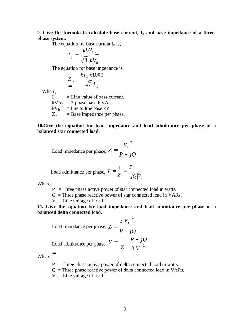
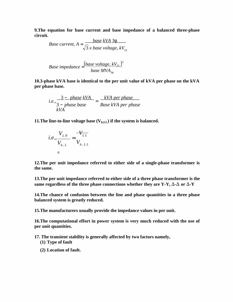
9. Give the formula to calculate base current, Ib and base impedance of a three-phase system.
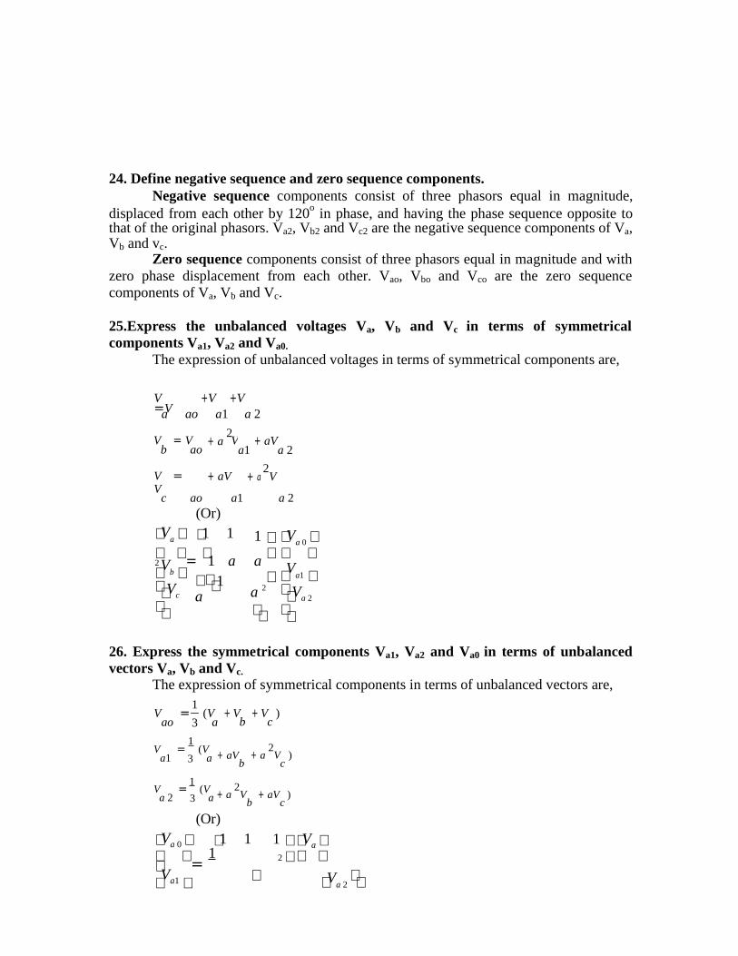
The equation for base current Ib is,
I = kVA b
3 kVb
The equation for base impedance is,
kVb x1000
Where,
Z b
= 3 I b
Ib = Line value of base current.kVAb = 3-phase base KVAkVb = line to line base kVZb = Base impedance per phase.
10.Give the equation for load impedance and load admittance per phase of abalanced star connected load.
Load impedance per phase, Z = VL
P − jQ
Where,
Load admittance per phase, Y = 1
Z=
P −
jQ VL
P = Three phase active power of star connected load in watts.Q = Three phase reactive power of star connected load in VARs.VL = Line voltage of load.
11. Give the equation for load impedance and load admittance per phase of abalanced delta connected load.
3 VLLoad impedance per phase, Z =
P − jQ1 P − jQ
Where,
Load admittance per phase, Y = Z
=3 VL
P = Three phase active power of delta connected load in watts.Q = Three phase reactive power of delta connected load in VARs.VL = Line voltage of load.
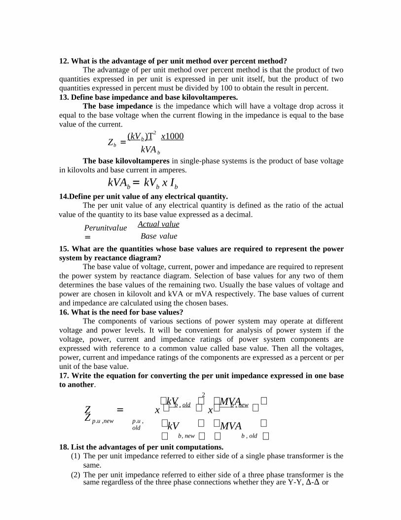
12. What is the advantage of per unit method over percent method?The advantage of per unit method over percent method is that the product of two
quantities expressed in per unit is expressed in per unit itself, but the product of twoquantities expressed in percent must be divided by 100 to obtain the result in percent.13. Define base impedance and base kilovoltamperes.
The base impedance is the impedance which will have a voltage drop across itequal to the base voltage when the current flowing in the impedance is equal to the basevalue of the current.
( kV )T2 x 1000Z = b
b kVA b
The base kilovoltamperes in single-phase systems is the product of base voltagein kilovolts and base current in amperes.
kVAb = kVb x Ib
14.Define per unit value of any electrical quantity.The per unit value of any electrical quantity is defined as the ratio of the actual
value of the quantity to its base value expressed as a decimal.
Perunitvalue =
Actual value
Base value
15. What are the quantities whose base values are required to represent the powersystem by reactance diagram?
The base value of voltage, current, power and impedance are required to representthe power system by reactance diagram. Selection of base values for any two of themdetermines the base values of the remaining two. Usually the base values of voltage andpower are chosen in kilovolt and kVA or mVA respectively. The base values of currentand impedance are calculated using the chosen bases.16. What is the need for base values?
The components of various sections of power system may operate at differentvoltage and power levels. It will be convenient for analysis of power system if thevoltage, power, current and impedance ratings of power system components areexpressed with reference to a common value called base value. Then all the voltages,power, current and impedance ratings of the components are expressed as a percent or perunit of the base value.17. Write the equation for converting the per unit impedance expressed in one baseto another.
kV2
MVA Z = Z
x b , old x b , new p.u ,new p.u ,
old kV MVA b, new b , old
18. List the advantages of per unit computations.(1) The per unit impedance referred to either side of a single phase transformer is the
same.(2) The per unit impedance referred to either side of a three phase transformer is the
same regardless of the three phase connections whether they are Y-Y, ∆-∆ or

∆-Y

(3) The chance of confusion between the line and phase quantities in a three phasebalanced system is greatly reduced.
(4) The manufacturers usually provide the impedance values in per unit.(5) The computational effort in power system is very much reduced with the use of
per unit quantities.19. What are the factors that affect the transient stability?
The transient stability is generally affected by two factors namely,(1) Type of fault (2) Location of fault.
20. List the methods of improving the transient stability limit of a power system.(1) Increase of system voltage, use of AVR.(2) Use of high speed excitation systems. (3) Reduction in system transfer reactance.(4) Use of high speed reclosing breakers.
21. What is meant by stability study?The procedure of determining the stability of a system upon occurrence of a
disturbance followed by various switch off and switch on actions is called a stabilitystudy.22. What is meant by short circuit fault?
Short circuit faults involve power conductor or conductors-to-ground or shortcircuit between conductors. These faults are characterized by increase in current and fallin voltage and frequency.23. What is a reactor?
Reactor is a coil, which has high inductive reactance as compared to its resistanceand is used to limit the short circuit current during fault conditions.24. Give the equation for transforming base kV on LV side to HV side of atransformer and vice versa.
Base kV on HV side = Base kV on LV side
Base kV on LV side = Base kV on HV side
x HV rating
LV rating
x LV rating
HV rating
25.Give the equation for base current and base impedance of a balanced three phasecircuit.
Base current, A = base kVA 3φ
3 x base voltage, kVLL
(base voltage, kV )2
Base impedance = LL
base MVA3φ
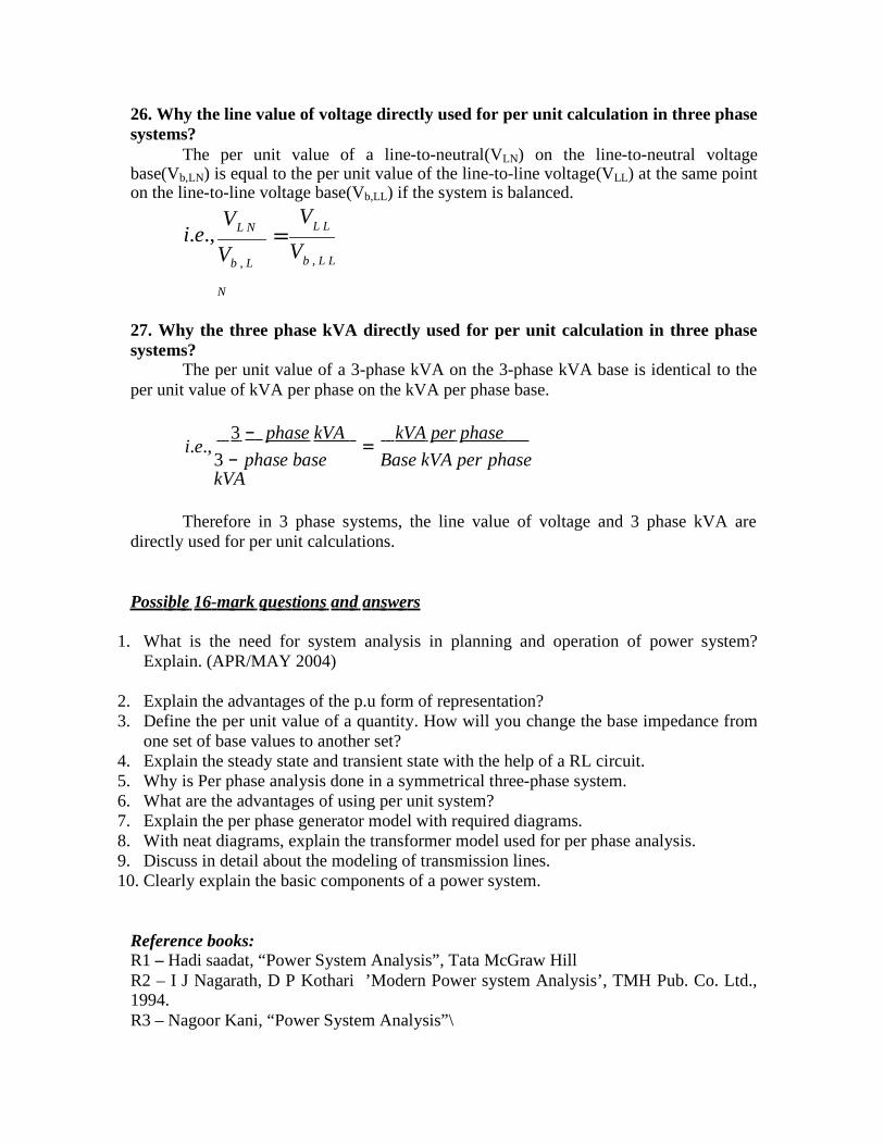
26. Why the line value of voltage directly used for per unit calculation in three phasesystems?
The per unit value of a line-to-neutral(VLN) on the line-to-neutral voltagebase(Vb,LN) is equal to the per unit value of the line-to-line voltage(VLL) at the same pointon the line-to-line voltage base(Vb,LL) if the system is balanced.
i.e.,VL N
Vb , L
N
= VL L
Vb , L L
27. Why the three phase kVA directly used for per unit calculation in three phasesystems?
The per unit value of a 3-phase kVA on the 3-phase kVA base is identical to theper unit value of kVA per phase on the kVA per phase base.
i.e., 3 − phase kVA
= kVA per phase
3 − phase base kVA
Base kVA per phase
Therefore in 3 phase systems, the line value of voltage and 3 phase kVA aredirectly used for per unit calculations.
Possi bl e 16-m ark qu estion s an d an sw ers
1. What is the need for system analysis in planning and operation of power system?Explain. (APR/MAY 2004)
2. Explain the advantages of the p.u form of representation?3. Define the per unit value of a quantity. How will you change the base impedance from
one set of base values to another set?4. Explain the steady state and transient state with the help of a RL circuit.5. Why is Per phase analysis done in a symmetrical three-phase system.6. What are the advantages of using per unit system?7. Explain the per phase generator model with required diagrams.8. With neat diagrams, explain the transformer model used for per phase analysis.9. Discuss in detail about the modeling of transmission lines.10. Clearly explain the basic components of a power system.
Reference books:R1 – Hadi saadat, “Power System Analysis”, Tata McGraw HillR2 – I J Nagarath, D P Kothari ’Modern Power system Analysis’, TMH Pub. Co. Ltd.,1994.R3 – Nagoor Kani, “Power System Analysis”\
b
b
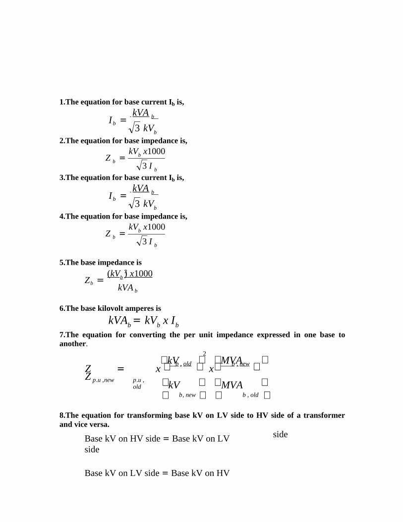
1.The equation for base current Ib is,
I = kVA b
3 kVb
2.The equation for base impedance is,kVb x1000
Z b =3 I b
3.The equation for base current Ib is,
I = kVA b
3 kVb
4.The equation for base impedance is,kVb x1000
Z b =3 I b
5.The base impedance is2
Z = ( kVb ) x 1000
b kVA b
6.The base kilovolt amperes is
kVAb = kVb x Ib
7.The equation for converting the per unit impedance expressed in one base toanother.
kV2
MVA Z = Z
x b , old x b , new p.u ,new p.u ,
old kV MVA b, new b , old
8.The equation for transforming base kV on LV side to HV side of a transformerand vice versa.
Base kV on HV side = Base kV on LV side
Base kV on LV side = Base kV on HV
side

x HV rating
LV rating
x LV rating
HV rating
9.The equation for base current and base impedance of a balanced three-phasecircuit.
Base current, A = base kVA 3φ
3 x base voltage, kVLL
(base voltage, kV )2
Base impedance = LL
base MVA3φ
10.3-phase kVA base is identical to the per unit value of kVA per phase on the kVAper phase base.
i.e., 3 − phase kVA
= kVA per phase
3 − phase base kVA
Base kVA per phase
11.The line-to-line voltage base (Vb,LL) if the system is balanced.
i.e.,VL N
Vb , L
N
= VL L
Vb , L L
12.The per unit impedance referred to either side of a single-phase transformer isthe same.
13.The per unit impedance referred to either side of a three phase transformer is thesame regardless of the three phase connections whether they are Y-Y, ∆-∆ or ∆-Y
14.The chance of confusion between the line and phase quantities in a three phasebalanced system is greatly reduced.
15.The manufacturers usually provide the impedance values in per unit.
16.The computational effort in power system is very much reduced with the use ofper unit quantities.
17. The transient stability is generally affected by two factors namely,(1) Type of fault
(2) Location of fault.
UNIT 2:MO DELL ING O F VA RIO US CO M PO NE NT S
Poss i b l e 2 - m ark q u e s t i o n s a n d a n s w e rs 1. Write the most important mode of operation of power system and mention themajor problems encountered with it.
Symmetrical steady state is the most important mode of operation of powersystem. Three major problems are encountered in this mode of operation. Theyare,
1) Load flow problem2) Optimal load scheduling problem3) Systems control problem
2.Why power flow analysis is made?Power flow analysis is performed to calculate the magnitude and phase angleof
voltages at the buses and also the active power and reactive voltamperes flow for thegiven terminal or bus conditions. The variables associated with each bus or node are,
a. Magnitude of voltage |V|b. Phase angle of voltage δc. Active power, Pd. Reactive voltamperes, Q
3. What is power flow study or load flow study?The study of various methods of solution to power system network is referred to
as load study. The solution provides the voltages at various buses, power flowing inVarious lines and line losses.
4. What are the information that are obtained from a load flow study?The information obtained from a load flow study are magnitude and phase angles
of bus voltages, real and reactive power flowing in each line and line losses. The loadflow solution also gives the initial conditions of the system when the transient behavior ofthe system is to be studied.
5. What is the need for load flow study? (MAY/JUNE 2006)The load flow study of a power system is essential to decide the best operation of
existing system and for planning the future expansion of the system. It is also essential for designing a new power system.
6. What are the works involved in a load flow study? (NOV/DEC 2004)The following has to be performed for a load flow study.a. Representation of the system by single line diagram.b. Formation of impedance diagram using the information in single line diagram.c. Formulation of network equationsd. Solution of network equations.
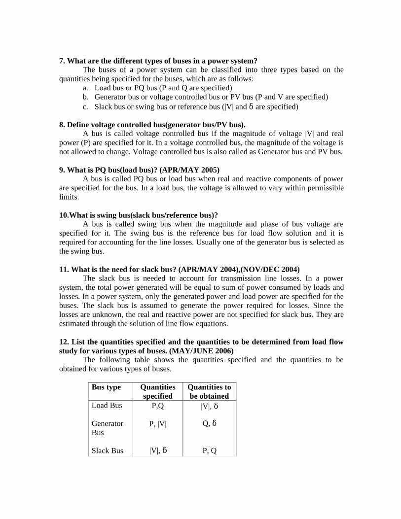
7. What are the different types of buses in a power system?The buses of a power system can be classified into three types based on the
quantities being specified for the buses, which are as follows:a. Load bus or PQ bus (P and Q are specified)b. Generator bus or voltage controlled bus or PV bus (P and V are specified)c. Slack bus or swing bus or reference bus (|V| and δ are specified)
8. Define voltage controlled bus(generator bus/PV bus).A bus is called voltage controlled bus if the magnitude of voltage |V| and real
power (P) are specified for it. In a voltage controlled bus, the magnitude of the voltage isnot allowed to change. Voltage controlled bus is also called as Generator bus and PV bus.
9. What is PQ bus(load bus)? (APR/MAY 2005)A bus is called PQ bus or load bus when real and reactive components of power
are specified for the bus. In a load bus, the voltage is allowed to vary within permissiblelimits.
10.What is swing bus(slack bus/reference bus)?A bus is called swing bus when the magnitude and phase of bus voltage are
specified for it. The swing bus is the reference bus for load flow solution and it isrequired for accounting for the line losses. Usually one of the generator bus is selected asthe swing bus.
11. What is the need for slack bus? (APR/MAY 2004),(NOV/DEC 2004)The slack bus is needed to account for transmission line losses. In a power
system, the total power generated will be equal to sum of power consumed by loads andlosses. In a power system, only the generated power and load power are specified for thebuses. The slack bus is assumed to generate the power required for losses. Since thelosses are unknown, the real and reactive power are not specified for slack bus. They areestimated through the solution of line flow equations.
12. List the quantities specified and the quantities to be determined from load flowstudy for various types of buses. (MAY/JUNE 2006)
The following table shows the quantities specified and the quantities to beobtained for various types of buses.
Bus type Quantitiesspecified
Quantities tobe obtained
Load Bus
GeneratorBus
Slack Bus
P,Q
P, |V|
|V|, δ
|V|, δ
Q, δ
P, Q
Y ppp
Y ppp
p f
p K
*
p p
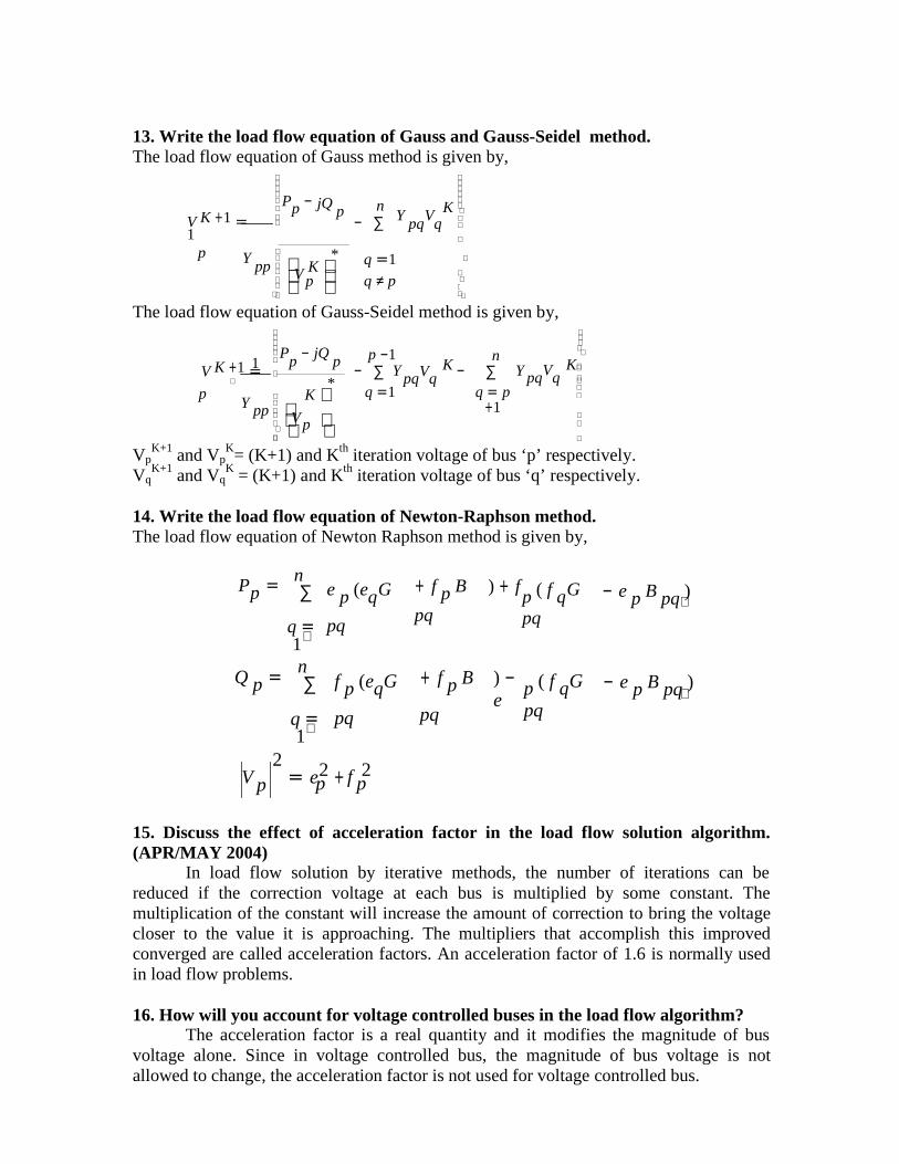
13. Write the load flow equation of Gauss and Gauss-Seidel method.The load flow equation of Gauss method is given by,
V K +1 = 1
p
P −
jQ p n− ∑
Y pqVq
K q =1
V
q ≠ p
The load flow equation of Gauss-Seidel method is given by,
1 Pp − jQ p p −1
K n
K
V K +1 =
p
K
*− ∑ Y
q =1pqVq − ∑ Y
q = p+1
pqVq
V
�
VpK+1 and Vp
K= (K+1) and Kth iteration voltage of bus ‘p’ respectively. Vq
K+1 and VqK = (K+1) and Kth iteration voltage of bus ‘q’ respectively.
14. Write the load flow equation of Newton-Raphson method.The load flow equation of Newton Raphson method is given by,
Pp =n∑��
q =1
e p (eqG
pq
+ f p B
pq
) + fp ( f qG
pq
− e p B pq )��
Q p =n∑�
�
q =1
f p (eqG
pq
+ f p B
pq
) − e
p ( f qG
pq
− e p B pq )��
V 2
= e2 + 2
15. Discuss the effect of acceleration factor in the load flow solution algorithm.(APR/MAY 2004)
In load flow solution by iterative methods, the number of iterations can bereduced if the correction voltage at each bus is multiplied by some constant. Themultiplication of the constant will increase the amount of correction to bring the voltagecloser to the value it is approaching. The multipliers that accomplish this improvedconverged are called acceleration factors. An acceleration factor of 1.6 is normally usedin load flow problems.
16. How will you account for voltage controlled buses in the load flow algorithm?The acceleration factor is a real quantity and it modifies the magnitude of bus
voltage alone. Since in voltage controlled bus, the magnitude of bus voltage is notallowed to change, the acceleration factor is not used for voltage controlled bus.
17. Why do we go for iterative methods to solve load flow problems?The load (or power) flow equations are nonlinear algebraic equations and so
explicit solution is not possible. The solution of nonlinear equations can be obtained onlyby iterative numerical techniques.18. What do you mean by a flat voltage start?
In iterative methods of load flow solution, the initial voltage of all buses exceptslack bus are assumed as 1+j0 p.u. This is referred to as flat voltage start.
19.When the generator bus is treated as load bus? What will be the reactive powerand bus voltage when the generator bus is treated as load bus?
If the reactive power of a generator bus violates the specified limits, then thegenerator bus is treated as load bus. The reactive power of that particular bus is equatedto the limit it has violated and the previous iteration value of bus voltage is used forcalculating current iteration value.
20. What are the advantages of Gauss-Seidel method?The advantages of Gauss-Seidel method are,
a. Calculations are simple and so the programming task is lessb. The memory requirement is lessc. Useful for small systems.
21.What are the disadvantages of Gauss-Seidel method?The disadvantages of Gauss-Seidel method are,
a. Requires large number of iterations to reach convergence.b. Not suitable for large systems.c. Convergence time increases with size of the system.
22.How approximation is performed in Newton-Raphson method?In Newton-Raphson method, the set of non-linear simultaneous (load flow)
equations are approximated to a set of linear simultaneous equations using Taylor’s seriesexpansion and the terms are limited to first order approximation.
23. What is Jacobian matrix? How the elements of Jacobian matrix are computed?The matrix formed from the derivates of load flow equations is called Jacobian
matrix and it is denoted by J.The elements of Jacobian matrix will change in every iteration. In each iteration,
the elements of the Jacobian matrix are obtained by partially differentiating the load flowequations with respect o unknown variable and then evaluating the first derivates usingthe solution of previous iteration.
24.What are the advantages of Newton-Raphson method?The advantages of Newton-Raphson method are,
a. This load flow method is faster, more reliable and he results are accurate.b. Requires less number of iterations for convergence.c. The number of iterations are independent of the size of the system.
d. Suitable for large system.
25.What are the disadvantages of Newton-Raphson method?The disadvantages of Newton-Raphson method are,
a. Programming is more complex.b. The memory requirement is more.c. Computational time per iteration is higher due to larger number of
calculations per iteration.
26.Mention (any) three advantages of N-R method over G-S method?The three advantages of N-R method over G-S method are,
a. The N-R method has quadratic convergence characteristics and so convergesfaster than G-S method.
b. The number of iterations for convergence is independent of the system in N-Rmethod.
c. In N-R method, the convergence is not affected by the choice of slack bus.
27.Compare G-S method and N-R methods of load flow solutions.G-S method N-R method
1. The variables are expressed inrectangular co-ordinates.
2. Computation time per iteration is less.3. It has linear convergence characteristics.
4. The number of iterations required forconvergence increase with size of thesystem.
5.The choice of slack bus is critical.
1. Variables are expressed in polar co-ordinates.
2. Computation time per iteration is more3. It has quadratic convergence
characteristics.4.The number of iterations are independentof the size of the system.
5. The choice of slack bus is arbitrary.
28.How the convergence of N-R method is speeded up?The convergence can be speeded up in N-R method by using Fast Decoupled
Load Flow (FDLF) algorithm. In FDLF method, the weak coupling between P-δ andQ-V are decoupled and then the equations are further simplified using theknowledge of practical operating conditions of a power system.
29. How the disadvantages of N-R method are overcome?The disadvantage of large memory requirement can be overcome by decoupling
the weak coupling between P-δ and Q-V (i.e., using decoupled load flow algorithm).The disadvantage of large computational time per iteration can be reduced by simplifyingthe decoupled load flow equations. The simplifications are based on the practicaloperating conditions of a power system.
30. Write the equation for power flow in the transmission line.The equation for power low in the transmission line (say p-q) at bus ‘p’ is given by,Spq = Ppq-jQpq
= Ep* ipq
= Ep*[Ep-Eq]Ypq + Ep
*Ep.(Ypq’/2)Sqp = Pqp-jQqp
= Eq* iqp
= Eq*[Eq-Ep]Ypq + Eq
*Eq.(Ypq’/2)
31.Define primitive network.Primitive network is a set of unconnected elements which provides information
regarding the characteristics of individual elements only. The performance equations of primitive network are given below.
V + E = ZI (In Impedance form)I + J = YV (In Admittance form)
where V and I are the element voltage and current vectors respectively.J and E are source vectors.Z and Y are the primitive Impedance and Admittance matrices respectively.
32. What is a bus?The meeting point of various components in a power system is called a bus. The
bus is a conductor made of copper (or) aluminium having negligible resistance. The busesare considered as points of constant voltage in a power system.
33.Explain bus incidence matrix.For the specific system, we can obtain the following relation (relation between
element voltage and bus voltage).V = A VBUS
where A is the bus incidence matrix, which is a rectangular and singular matrix.Itselements are found as per the following rules.
aik = 1, if ith element is incident to and oriented away from the kth node (bus).= -1, if ith element is incident to but oriented towards the kth node.= 0, if ith element is not incident to the kth node.
34. What is bus admittance matrix? (MAY/JUNE 2006)The matrix consisting of the self and mutual admittance of the power system
network is called bus admittance matrix. It is given by the admittance matrix Y in thenode basis matrix equation of a power system and it is denoted as Ybus. Bus admittancematrix is a symmetrical matrix.35. Write the equation for the bus admittance matrix.
The equation for bus admittance matrix is,YbusV = I
whereYbus = Bus admittance matrix of order (n x n )V = Bus voltage matrix of order (n x1)I = Current source matrix of order (n x1)n = Number of independent buses in the system
∆
36. Give the matrix notation of YbusV = I
Y11 Y12 Y13 . . . Y1n V1 I11 Y21
Y31
Y22
Y32
Y23
Y33
. . .
. . .
Y2 n Y
3n
V2 V3
I 22 I 33
. . . . . = . . . . . . .
. .
. . . .
Yn1 Yn 2 Yn3 . . . Ynn Vn I nn
37. Give the equation to find the kth bus voltage.The equation to find the kth bus voltage is,
1Vk = [∆1k I 11+∆ 2 k I 22+∆ 3k I 33+... + ∆ nk I nn ]∆1 n
Vk = ∑ ∆ jk I
jjj
=1
where ∆ = Determinant of Ybus matrix.Ijj = Sum of the currents injecting current to node j.∆jk = Cofactor of the element Yjk of bus admittance matrix.
38.Mention the advantages of bus admittance matrix, Ybus.i) Data preparation is simple.ii) Formation and modification is easy.iii) Since the bus admittance matrix is sparse matrix(i.e., most of its elements are
zero), the computer memory requirements are less.
P ossib l e 16 - m ar k qu e s ti ons a nd a ns w e r s 1.With the help of a neat flow chart, explain the Newton-Raphson method of load flowsolution when the system contains voltage controlled busses in addition to swing bus andload bus.
(APR/MAY 2004)2.Compare Gauss-Seidel method and Newton-Raphson method of load flow studies
(NOV/DEC 2004)3.Explain clearly with detailed flowchart, the computational procedure for load flowsolution using N-R method when the system contains all types of buses.
(NOV/DEC 2004)4.Explain the step by step computational procedure for the Newton-Raphson method ofload flow studies.
(APR/MAY 2005)5. Explain bus classification in power flow analysis with their known and unknown

quantities.

6. Derive the static load flow equations of n-Bus system.(APR/MAY 2005)
7. Explain the step by step computational procedure for the Gauss-Seidel method of loadflow studies (MAY/JUNE 2006)
8. Derive the basic equations for the load flow study using Gauss-Seidel method. Withrespect to this method, explain the following:
a. Acceleration factor.b. Handling of PV buses.
9. Draw the representation schemes fora. Phase shifting transformerb. Tap changing transformer
10. Draw the mathematical model of phase shifting transformer to be used in power flowanalysis.
11. Give the advantages and disadvantages of Gauss-Seidel method and Newton-Raphsonmethod of load flow analysis.
12. Write the equations to calculate Slack bus power, Transmission losses and Lineflows.
Reference books:R1 – Hadi saadat, “Power System Analysis”, Tata McGraw HillR2 – I J Nagarath , D P Kothari ’Modern Power system Analysis’, TMH Pub. Co. Ltd.,1994.R3 – Nagoor Kani, “Power System Analysis”
UNIT 3:PO WE R FL O W ANAL YS IS
P ossib l e 2 m ar k qu e s ti ons: 1. What is the need for short circuit studies or fault analysis?
The short circuit studies are essential in order to design or develop the protectiveschemes for various parts of the system. The protective scheme consists of current andvoltage sensing devices, protective relays and circuit breakers. The selection of thesedevices mainly depends on various currents that may flow in the fault conditions.
2. What is the reason for transients during short circuits?The faults or short circuits are associated with sudden change in currents. Most of
the components of the power system have inductive property which opposes any suddenchange in currents, so the faults are associated with transients.
3. What is meant by a fault?A fault in a circuit is any failure which interrupts with the normal flow of current.
The faults are associated with abnormal change in current, voltage and frequency of thepower system. The faults may cause damage to the equipments, if it is allowed to persistfor a long time. Hence every part of a system has been protected by means of relays andcircuit breakers to sense the faults and to isolate the faulty part from the healthy part ofthe network in the event of fault
4. Why faults occur in a power system?Faults occur in a power system due to insulation failure of equipments, flashover
of lines initiated by a lightening stroke, permanent damage to conductors and towers oraccidental faulty operations.
5. How are the faults classified?In one method, the faults are classified as,
1. Shunt faults - due to short circuits in conductors2. Series faults - due to open conductors.
In another method,1. Symmetrical faults - fault currents are equal in all the phases and can be
analyzed on per phase basis2. Unsymmetrical faults – fault currents are unbalanced and so they can be
analyzed only using symmetrical components.
6. List the various types of shunt and series faults.Various types of shunt faults are
1. Single line-to-ground fault2. Line-to-line fault
Load flow studies Fault analysis1. Both resistances and reactances are
Considered.2. Bus admittance matrix is useful.3. The exact voltages and currents are to be
determined.
Resistances are neglected.
Bus impedance matrix is used.The voltages can be safely assumed as 1p.u. and the prefault current can beneglected.
3. Double line-to-ground fault4. Three phase fault
Various types of series faults are,1. One open conductor fault2. Two open conductor fault
7. What is meant by symmetrical fault?The fault is called symmetrical fault if the fault current is equal in all the phases.
This fault conditions are analyzed on per phase basis using Thevenin’s theorem or usingbus impedance matrix. The three-phase fault is the only symmetrical fault.
8. List out the differences in representing the power system for load flow and shortcircuit studies.
9. For a fault at a given location, rank the various faults in the order ofseverity.
In a power system, the most severe fault is three phase fault and less severe faultis open conductor fault. The various faults in the order of decreasing severity are,
1) 3 phase fault2) Double line-to-ground fault3) Line-to-line fault4) Single line-to-ground fault5) Open conductor fault
10. What is meant by fault calculations?The fault condition of a power system can be divided into sub transient, transient,
and steady state periods. The currents in the various parts of the system and in the faultlocations are different in these periods. The estimation of these currents for various typesof faults at various locations in the system is commonly referred to as fault calculations.
11. What are the assumptions made in short circuit studies of a large power systemnetwork? (APR/MAY 2005)1) The phase to neutral emfs of all generators remain constant, balanced and unaffected
by the faults.2) Each generator is represented by an emf behind either the subtransient or transient
reactance depending upon whether the short circuit current is to be found immediatelyafter the short circuit or after about 3 – 4 cycles.
3) Load currents may often be neglected in comparison with faultcurrents.4) All network impedances are purely reactive. Thus the series resistances of lines and
transformers are neglected in comparison with their resistances.

5) Shunt capacitances and shunt branches of transformers are neglected. Hence,transformer reactances are taken as their leakage reactances.
12. What is synchronous reactance?The synchronous reactance is the ratio of induced emf and the steady state rms
current (i.e., it is the reactance of a synchronous machine under steady state condition). Itis the sum of leakage reactance and the reactance representing armature reaction. It isgiven by,
Xs = Xl + Xa
Where,Xs = Synchronous reactanceXl = Leakage reactanceXa = Armature reaction reactance.
13. Define subtransient reactance.(APR/MAY 2004)The subtransient reactance is the ratio of induced emf on no-load and the
subtransient symmetrical rms current, (i.e., it is the reactance of a synchronous machineunder subtransient condition). It is given by,
Where
Subtransient reactance, X d
Xl = Leakage reactance
''
=
E g
I ''
= X l + 1
X a
1
+ 1
X f
+ 1
X dw
Xa = Armature reaction reactanceXf = Field winding reactanceXdw = Damper winding reactance.
14. Define transient reactance.The transient reactance is the ratio of induced emf on no-load and the transient
symmetrical rms current. (i.e.,it is the reactance of synchronous machine under transient condition). It is given by,
Where
Transient reactance,E X d
' = g
I '= X l +
1
X a
1
+ 1
X f
Xl = Leakage reactan Xa = Armature reaction reactance Xf = Field windingreactance
15.What is the significance of subtransient reactance and transient reactance inshort circuit studies?
The subtransient reactance can be used to estimate the initial value of fault currentimmediately on the occurrence of the fault. The maximum momentary short circuitcurrent rating of the circuit breaker used for protection or fault clearing should be lessthan this initial fault current.
The transient reactance is used to estimate the transient state fault current. Most ofthe circuit breakers open their contacts only during this period. Therefore for a circuit
E
E
E '' ''
g
E '' ''
E
'
'
m
breaker used for fault clearing (or protection), its interrupting short circuit current ratingshould be less than the transient fault current.
16. Write down the equation determining fault current in a generator when itsreactance is known.The equation is,
E gI = ,
X d
NE
g I ' =
X'
d
whereI = Steady state symmetrical fault current
I ' = Transient symmetrical fault current
Xd = Direct axis synchronous reactanceXd
’ = Direct axis transient reactance
E g = RMS voltage from one terminal to neutral at no load.
17.Write the equation for subtransient and transient internal voltage of thegenerator.The equation for subtransient internal voltage is,
g = Vt
+jI L X d
Transient internal voltage is,' '
where
E g = Vt
+
’’
jI L X d
Eg = Subtransient internal voltage of generator’ = Transient internal voltage of generator
Vt = Terminal voltageIL = Load currentXd
’’ =Direct axis subtransient reactanceXd
’ =Direct axis transient reactance
18.Write the equation for subtransient and transient internal voltage of the motor.The equation for subtransient internal voltage is,
m = Vt
−jI L X d
Transient internal voltage is,
wherem = Vt
−jI L X d s
’’ = Subtransient internal voltage of generator

Em’ = Transient internal voltage of generator
Vt = Terminal voltageIL = Load currentXd
’’ =Direct axis subtransient reactance
Xd’ =Direct axis transient reactance
19. How symmetrical faults are analyzed?The symmetrical faults are analyzed using per unit reactance diagram of the powersystem. Once the reactance diagram is formed, then the fault is simulated by short circuit or by connecting the fault impedance at the fault point. The currents and voltages at various parts of the system can be estimated by any of the following methods.
1) Using Kirchoff’s laws2) Using Thevenin’s theorem3) By forming bus impedance matrix.
20. Define doubling effect and DC off-set current.Doubling effect:
If a symmetrical fault occurs when the voltage wave is going through zero thenthe maximum momentary short circuit current will be double the value of maximumsymmetrical short circuit current. This effect is called doubling effect.DC off-set current:
The unidirectional transient component of short circuit current is called DC off-set current.
21.Differentiate between subtransient and transient reactance.
Subtransient reactance Transient reactance
1) This is the ratio of induced emf andsubtransient current.2) Flux created by induced currents in thedamper winding is included.3) This is the smallest reactance among thereactance values.4) This cannot be extrapolated.
1) This is the ratio of induced emf andtransient current.2) There is no damper winding and henceno flux is created.3) This is larger than the subtransientreactance.4) This can be extrapolated backwards intime
22.What are symmetrical components?An unbalanced system of N related vectors can be resolved into N systems of
balanced vectors called symmetrical components. Positive sequence componentsNegative sequence componentsZero sequence components.
23. Write the symmetrical components of three phase system.In a 3-phase system, the three unbalanced vectors (either current or voltage
vectors) can be resolved into three balanced system of vectors. They are,1) Positive sequence components2) Negative sequence components3) Zero sequence components.
V
24. Define negative sequence and zero sequence components.Negative sequence components consist of three phasors equal in magnitude,
displaced from each other by 120o in phase, and having the phase sequence opposite tothat of the original phasors. Va2, Vb2 and Vc2 are the negative sequence components of Va,Vb and vc.
Zero sequence components consist of three phasors equal in magnitude and withzero phase displacement from each other. Vao, Vbo and Vco are the zero sequencecomponents of Va, Vb and Vc.
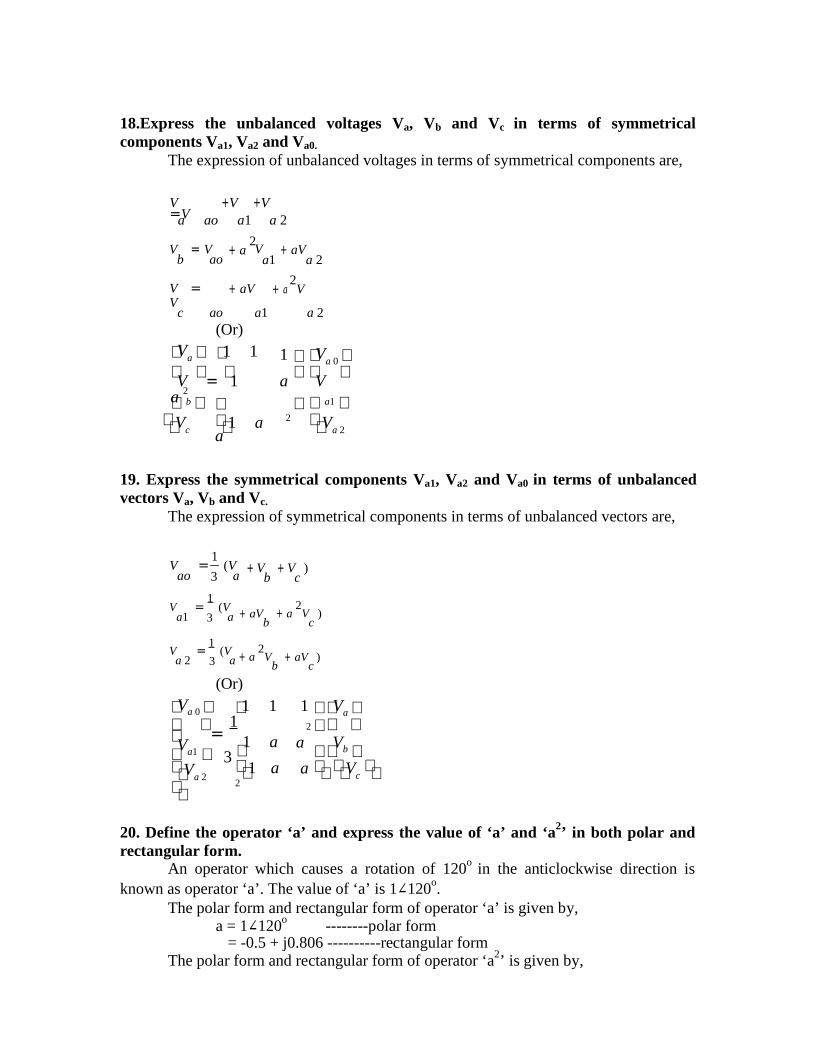
25.Express the unbalanced voltages Va, Vb and Vc in terms of symmetricalcomponents Va1, Va2 and Va0.
The expression of unbalanced voltages in terms of symmetrical components are,
V =V
+V +Va ao a1 a 2
V = Vb ao
+ a 2
a1+ aV
a 2
V = V
+ aV + a 2V
c ao(Or)
a1 a 2
Va 1 1 1 V
a 0 = 1 a2 a V
b Vc
1 a
a 2
Va1
Va 2
26. Express the symmetrical components Va1, Va2 and Va0 in terms of unbalancedvectors Va, Vb and Vc.
The expression of symmetrical components in terms of unbalanced vectors are,1
V = (Vao 3 a
+ V + V )b c
1V = (V
a1 3 a + aVb
+ a 2
V )c
1V = (V
a 2 3 a + a 2
Vb
+ aV )c
Va 0 (Or)
1 1 1 Va
= 1
2
Va1 Va 2

3 1 a
1 a 2a Vb
a Vc
27. Define the operator ‘a’ and express the value of ‘a’ and ‘a2’ in both polar andrectangular form.
An operator which causes a rotation of 120o in the anticlockwise direction isknown as operator ‘a’. The value of ‘a’ is 1∠120o.
The polar form and rectangular form of operator ‘a’ is given by,a = 1∠120o --------polar form
= -0.5 + j0.806 ----------rectangular formThe polar form and rectangular form of operator ‘a2’ is given by,
a2 = 1∠240o --------polar form= -0.5 - j0.806 ----------rectangular form
28.what are sequence impedances and sequence networks?The sequence impedances are the impedances offered by the devices or
components for the like sequence component of the current.The single phase equivalent circuit of a power system consisting of impedances to
current of any one sequence only is called sequence network.
29. What assumption is made at the star / delta transformer?It is that the positive sequence quantities on the HV side lead their corresponding
positive sequence quantities on the LV side by 30o. The reverse is the case for negativesequence quantities wherein HV quantities lag the corresponding LV quantities by 30o.
30.What is an unsymmetrical fault? List the various unsymmetrical faults.The fault is called unsymmetrical fault if the fault current is not equal in all the
phases. The unsymmetrical faults in a power system are,1) Single line-to-ground fault.2) Line-to-line fault.3) Double line-to-ground fault4) Open conductor fault.
31.Define positive sequence and negative sequence impedances.The positive sequence impedance of an equipment is the impedance offered by
the equipment to the flow of positive sequence current.The negative sequence impedance of an equipment is the impedance offered by
the equipment to the flow of negative sequence current.
P ossib l e 16 m ar ks :1. Explain the need for short circuit studies.2. Draw the relationship between the phase components and the sequence
components.3. The phase ‘b’ of a three phase circuit is open. The currents in phases ‘c’ and ‘a’
are I and –I respectively. Determine the positive, negative and zero sequencecomponents of the current in phase ‘a’.
4. With the help of a detailed flow chart, explain how a symmetrical fault can beanalysed using ZBus.
5. What are the various types of faults? Discuss their frequency of occurrence andseverity? Find the fault current when an L-L-G fault occurs at the terminals of an unloaded generator.
6. Derive an expression for the positive sequence current Ia1 of an unloadedgenerator when it is subjected to a double line to ground fault.(APR/MAY 2004).
7. Explain the short circuit model of a synchronous machine under short circuitconditions.
8. What symmetrical components? Explain the symmetrical componenttransformation.
9. What is meant by sequence impedance? Explain the sequence network of anunloaded generator.
10. Explain the procedure for making short circuit studies of a large power systemusing digital computer. Illustrate the answer by considering a symmetrical fault.(NOV/DEC 2004)
Reference books:R1 – Hadi saadat, “Power System Analysis”, Tata McGraw HillR2 – I J Nagarath , D P Kothari ’Modern Power system Analysis’, TMH Pub. Co. Ltd.,1994.R3 – Nagoor Kani, “Power System Analysis”
UNIT 4: SHO RT CIRCUIT ANAL YS IS
Possibl e 2 mark qu esti on s:
1. What is meant by a fault?A fault in a circuit is any failure which interrupts with the normal flow of current.
The faults are associated with abnormal change in current, voltage and frequency of thepower system. The faults may cause damage to the equipments, if it is allowed to persistfor a long time.
2. Give the reason for faults in power system?Faults occur in a power system due to insulation failure of equipments, flashover
of lines initiated by a lightening stroke, permanent damage to conductors and towers oraccidental faulty operations.
3. List the various types of symmetrical and unsymmetrical faults. (MAY/JUNE2006)Symmetrical fault:
5. Three phase faultUnsymmetrical faults:
6. Single line-to-ground fault7. Line-to-line fault8. Double line-to-ground fault
4. For a fault at a given location, rank the various faults in the order ofseverity.
In a power system, the most severe fault is three phase fault and less severe faultis open conductor fault. The various faults in the order of decreasing severity are,
6) 3 phase fault7) Double line-to-ground fault8) Line-to-line fault9) Single line-to-ground fault10) Open conductor fault
5. What is meant by fault calculations?The fault condition of a power system can be divided into subtransient, transient,
and steady state periods. The currents in the various parts of the system and in the faultlocations are different in these periods. The estimation of these currents for various typesof faults at various locations in the system is commonly referred to as fault calculations.
6. What is synchronous reactance?The synchronous reactance is the ratio of induced emf and the steady state rms
current (i.e., it is the reactance of a synchronous machine under steady state condition). Itis the sum of leakage reactance and the reactance representing armature reaction. It isgiven by,
Xs = Xl + Xa
Where,Xs = Synchronous reactanceXl = Leakage reactanceXa = Armature reaction reactance.
7. Define subtransient reactance.(APR/MAY 2004)The subtransient reactance is the ratio of induced emf on no-load and the
subtransient symmetrical rms current, (i.e., it is the reactance of a synchronous machineunder subtransient condition). It is given by,
Where
Subtransient reactance, X d
Xl = Leakage reactance
''
=
E g
I ''
= X l + 1
X a
1
+ 1
X f
+ 1
X dw
Xa = Armature reaction reactanceXf = Field winding reactanceXdw = Damper winding reactance.
8. Define transient reactance.The transient reactance is the ratio of induced emf on no-load and the transient
symmetrical rms current. (i.e.,it is the reactance of synchronous machine under transient condition). It is given by,
Transient reactance,E X d
' = g
I '= X l +
1
X a
1
+ 1
X f
Where Xl = Leakage reactance Xa = Armature reaction reactanceXf = Field winding reactance
9.What is the significance of subtransient reactance and transient reactance in shortcircuit studies?
The subtransient reactance can be used to estimate the initial value of fault currentimmediately on the occurrence of the fault. The maximum momentary short circuitcurrent rating of the circuit breaker used for protection or fault clearing should be lessthan this initial fault current.
The transient reactance is used to estimate the transient state fault current. Most ofthe circuit breakers open their contacts only during this period. Therefore for a circuit

E
E
E '' ''
g
E '' ''
E
'
'
m
breaker used for fault clearing (or protection), its interrupting short circuit current ratingshould be less than the transient fault current.
10. Write down the equation determining fault current in a generator when itsreactance is known.The equation is,
E gI = ,
X d
NE
g I ' =
X'
d
whereI = Steady state symmetrical fault current
I ' = Transient symmetrical fault current
Xd = Direct axis synchronous reactanceXd
’ = Direct axis transient reactance
E g = RMS voltage from one terminal to neutral at no load.
11.Write the equation for subtransient and transient internal voltage of thegenerator.The equation for subtransient internal voltage is,
g = Vt
+jI L X d
Transient internal voltage is,' '
where
E g = Vt
+
’’
jI L X d
Eg = Subtransient internal voltage of generator’ = Transient internal voltage of generator
Vt = Terminal voltageIL = Load currentXd
’’ =Direct axis subtransient reactanceXd
’ =Direct axis transient reactance
12.Write the equation for subtransient and transient internal voltage of the motor.The equation for subtransient internal voltage is,
m = Vt
−jI L X d
Transient internal voltage is,
wherem = Vt
−jI L X d s
’’ = Subtransient internal voltage of generator

Em’ = Transient internal voltage of generator
Vt = Terminal voltageIL = Load currentXd
’’ =Direct axis subtransient reactance
Xd’ =Direct axis transient reactance
13. Define doubling effect and DC off-set current.Doubling effect:
If a symmetrical fault occurs when the voltage wave is going through zero thenthe maximum momentary short circuit current will be double the value of maximumsymmetrical short circuit current. This effect is called doubling effect.DC off-set current:
The unidirectional transient component of short circuit current is called DC off-set current.
14.Differentiate between subtransient and transient reactance.
Subtransient reactance Transient reactance
1) This is the ratio of induced emf andsubtransient current.2) Flux created by induced currents in thedamper winding is included.3) This is the smallest reactance among thereactance values.4) This cannot be extrapolated.
1) This is the ratio of induced emf andtransient current.2) There is no damper winding and henceno flux is created.3) This is larger than the subtransientreactance.4) This can be extrapolated backwards intime
15.What are symmetrical components?An unbalanced system of N related vectors can be resolved into N systems ofbalanced vectors called symmetrical components. Positive sequence components
Negative sequence component Zero sequence components.
16. Write the symmetrical components of three phase system. (MAY/JUNE 2006)In a 3-phase system, the three unbalanced vectors (either current or voltage
vectors) can be resolved into three balanced system of vectors. They are,4) Positive sequence components5) Negative sequence components6) Zero sequence components.
17. Define negative sequence and zero sequence components.Negative sequence components consist of three phasors equal in magnitude,
displaced from each other by 120o in phase, and having the phase sequence opposite tothat of the original phasors. Va2, Vb2 and Vc2 are the negative sequence components of Va,Vb and vc.
Zero sequence components consist of three phasors equal in magnitude and withzero phase displacement from each other. Vao, Vbo and Vco are the zero sequencecomponents of Va, Vb and Vc.
V
18.Express the unbalanced voltages Va, Vb and Vc in terms of symmetricalcomponents Va1, Va2 and Va0.
The expression of unbalanced voltages in terms of symmetrical components are,
V =V
+V +Va ao a1 a 2
V = Vb ao
+ a 2
a1+ aV
a 2
V = V
+ aV + a 2V
c ao(Or)
a1 a 2
Va 1 1 1 Va 0 V = 1 a 2
a V
b a1 2Vc
1 a a
Va 2
19. Express the symmetrical components Va1, Va2 and Va0 in terms of unbalancedvectors Va, Vb and Vc.
The expression of symmetrical components in terms of unbalanced vectors are,
1V = (V
ao 3 a+ V + V )
b c
1V = (V
a1 3 a + aVb
+ a 2
V )c
1V = (V
a 2 3 a + a 2
Vb
+ aV )c
Va 0 (Or)
1 1 1 Va
= 1
2
Va1 Va 2
3 1 a
1 a2
a Vb a Vc
20. Define the operator ‘a’ and express the value of ‘a’ and ‘a2’ in both polar andrectangular form.
An operator which causes a rotation of 120o in the anticlockwise direction isknown as operator ‘a’. The value of ‘a’ is 1∠120o.
The polar form and rectangular form of operator ‘a’ is given by,a = 1∠120o --------polar form
= -0.5 + j0.806 ----------rectangular formThe polar form and rectangular form of operator ‘a2’ is given by,

a2 = 1∠240o --------polar form= -0.5 - j0.806 ----------rectangular form

30
P oss ibl e 16 m a r k s :11. Draw the relationship between the phase components and the sequence
components..
12. Derive the expression for fault current for a double line to ground fault in anunloaded generator in terms of symmetrical components. (MAY/JUNE 2006)
13. Derive the expression for fault current for a single line-to-ground fault in a powersystem faulted through fault impedance Zf.
14. Explain the need for short circuit studies
15. The phase ‘b’ of a three phase circuit is open. The currents in phases ‘c’ and ‘a’are I and –I respectively. Determine the Fpositive, negative and zero sequencecomponents of the current in phase ‘a’.
16. What are the various types of faults? Discuss their frequency of occurrence andseverity?
17. Find the fault current when an L-L-G fault occurs at the terminals of an unloadedgenerator. Derive an expression for the positive sequence current Ia1 of anunloaded generator when it is subjected to a double line to ground fault.(APR/MAY 2004).
18. Explain the short circuit model of a synchronous machine under short circuitconditions. What symmetrical components? Explain the symmetrical componenttransformation.
19. Write about the impedances in phase and sequence form.
20. What is meant by sequence impedance? Explain the sequence network of anunloaded generator.
21. Explain the procedure for making short circuit studies of a large power systemusing digital computer. Illustrate the answer by considering a symmetrical fault.(NOV/DEC 2004)
31
UNIT 5:ST AB IL IT Y ANAL YS IS
Poss i b l e 2 m arks 1.Define Stability.
The stability of a system is defined as the ability of power system to return to astable operation in which various synchronous machines of the system remain insynchronism or ‘in step’ with each other, when it is subjected to a disturbance.
2. Define steady state stability.The steady state stability is defined as the ability of a power system to remain
stable i.e., without loosing synchronism for small disturbances.
3. Define transient stability.The transient stability is defined as the ability of a power system to remain stable
i.e., without loosing synchronism for large disturbances.
4.Write any three assumptions upon transient stability.a. Rotor speed is assumed to be synchronous. In fact, it varies insignificantly
during the course of the stability study.b. Shunt capacitances are not difficult to account for in a stability study.c. Loads are modeled as constant admittances.
5. What is meant by steady state stability limit?When the load on the system is increased gradually,maximum power that can be
transmitted without losing synchronism is termed as steady state stability limit. In steadystate, the power transferred by synchronous machine of a power system is always lessthan the steady state stability limit.
6. What is transient stability limit?When the load on the system is increased suddenly, maximum power that can be
transmitted without losing synchronism is termed as transient state stabilitylimit.
Normally, steady state stability limit is greater than transient state stability limit.
7. How to improve the transient stability limit of power system?a. Increase of system voltagesb. Use of high speed excitation systems. c. Reduction in system transfer reactanced. Use of high speed reclosing breakers.
8. What is stability study?The procedure of determining the stability of a system upon occurrence of a
disturbance followed by various switching off and switching on actions is called stabilitystudy.
32
9.How do you classify steady state stability limit. Define them.Depending on the nature of the disturbance, the steady state stability limit is
classified into,a. Static stability limit refers to steady state stability limit that prevails without
the aid of regulating devices.b. Dynamic stability limit refers to steady state stability limit prevailing in an
unstable system with the help of regulating devices such as speed governors,voltage regulators, etc.
10.What are the machine problems seen in the stability study.1. Those having one machine of finite inertia machines swinging with respect to
an infinite bus2. Those having two finite inertia machines swinging with respect to each other.
11. Give the expression for swing equation. Explain each term along with theirunits.(APR/MAY 2005)
Where H = Inertia constant in MJ/MVA.f = Frequency in Hz.M = Inertia constant in p.u.Pm= Mechanical power input to the system (neglecting mechanical losses) in p.u.Pe = Electrical power output of the system (neglecting electrical losses) in p.u.
12. What are the assumptions made in solving swing equation?1) Mechanical power input to the machine remains constant during the period of
electromechanical transient of interest.2) Rotor speed changes are insignificant that had already been ignored in
formulating the swing equations.3) Effect of voltage regulating loop during the transient are ignored.
13. Define swing curve. What is the use of swing curve?The swing curve is the plot or graph between the power angle δ, and time, t.
It is usually plotted for a transient state to study the nature of variation in δ fora sudden large disturbance. From the nature of variations of δ, the stability of a systemfor any disturbance can be determined.
14.Give the control schemes included in stability control techniques?The control schemes included in the stability control techniques are:
a. Excitation systems b.Turbine valve controlc.Single pole operation of circuit breakersd.Faster fault clearing times
33
15.What are the systems design strategies aimed at lowering system reactance?The system design strategies aimed at lowering system reactance are:
a. Minimum transformer reactance b.Series capacitor compensation of linesc.Additional transmission lines.
16.What are coherent machines? (APR/MAY 2004)Machines which swing together are called coherent machines. When both ωs and δ
are expressed in electrical degrees or radians, the swing equations for coherent machinescan be combined together even though the rated speeds are different. This is used in stability studies involving many machines.
17.State equal area criterion. (NOV/DEC 2004)In a two machine system under the usual assumptions of constant input , no damping
and constant voltage being transient reactance , the angle between the machines either increases or else, after all disturbances have occurred oscillates with constant amplitude. There is a simple graphical method of determining whether the system comes to rest withrespect to each other. This is known as equal area criterion
18.What are various faults that increase severity of equal area criterion?
The various faults that increases severity of equal area criterion are,A Single line to ground faultA Line to line faultA Double line to ground faultA Three phase fault
19.Give the expression for critical clearing timeThe expression for the critical clearing time tcr is given by
tcr =
Where, H is the constantδcr is the critical clearing angleδo is the rotor anglePm is the mechanical powerωs is the synchronous speed
20.List the types of disturbances that may occur in a single machine infinite bus bar system of the equal area criterion stability
The types of disturbances that may occur are,Sudden change in mechanical input Effect of clearing time on stability Sudden loss of one of parallel linesSudden short circuit on one of parallel lines
i) Short circuit at one end of lineii) Short circuit away from line endsiii) Reclosure
34
21.Define critical clearing angleThe critical clearing angle δcc is the maximum allowable change in the power angle δ
before clearing the fault , without loss of synchronism.
22. Define critical clearing time.
The critical clearing time , tcc can be defined as the maximum time delay that can be allowed to clear a fault without loss of synchronism . The time corresponding to the critical clearing angle is called critical clearing time tcc.
23. What are the assumptions that are made inorder to simplify the computational task in stability studies?
The assumptions are,• The D.C offset currents and harmonic components are neglected. The
currents and voltages are assumed to have fundamental componentalone.
• The symmetrical components are used for the representation ofunbalanced faults.
• It is assumed that the machine speed variations will not affect thegenerated voltage.
24.What is Multimachine stability?If a system has any number of machines, then each machine is listed for stability by
advancing the angular position, δ of its internal voltage and noting whether the electric power output of the machine increases (or) decreases. If it increases,i.e if ∂Pn / ∂δn > 0
then machine n is stable. If every machine is stable, then the system having any number of machine is stable.
25. What is meant by an infinite bus?The connection or disconnection of a single small machine on a large system would
not affect the magnitude and phase of the voltage and frequency. Such a system of constant voltage and constant frequency regardless of the load is called infinite bus barsystem or infinite bus.
26.List the assumptions made in multimachine stability studies.The assumptions made are,
• The mechanical power input to each machine remains constant duringthe entire period of the swing curve computation
• Damping power is negligible• Each machine may be represented by a constant transient reactance in
series with a constant transient voltage.• The mechanical rotor angle of each machine coincides with δ ,
the electrical phase angle of the transient internal voltage.
27. Explain the concept synchronous speed.
35
The mechanical torque Tm and the electrical torque Te are considered positive for synchronous generator. Tm is the resultant shaft torque which tends to accelerate the rotor in the positive θm direction of rotation . Under steady-state operation of the generator Tm and Te are equal and the accelerating torque Ta is zero. Hence there is noacceleration of deceleration of the rotor, masses and the resultant constant speed is the synchronous speed.
P ossib l e 16 m ar ks 1. Derive the swing equation for a single machine connected to infinite bus system. Statethe assumptions if any and state the usefulness of this equation. Neglect the damping.
R4-Pg.No 2462.Discuss the various factors affecting the transient stability of the system.
R1-Pg.No 5.423. With the help of a neat flowchart, explain the modified Euler method of solving theswing equations.
R1-Pg.No 5.694.State the bad effects of instability. Distinguish between steady state and transientstability.
R1-Pg.No5.65.Write short notes on assumptions made in deducing equal area criterion.
R1-Pg.No5.45, R2 - 3466. State and explain equal area criterion. How do you apply equal area criterion to findthe maximum additional load.
R1-Pg.No5.47, R4-2567. Describe the equal area criterion for transient stability analysis of a system.
R1-Pg.No5.45 APR/MAY 20048. Mention the assumptions clearly and developing necessary equations, describe the stepby step solution of swing bus.
R1-Pg.No5.28 APR/MAY 20049. Derive the swing equation of a synchronous machine swinging against an infinite bus.Clearly state the assumptions in deducing the swing equation.
R1-Pg.No5.8 NOV/DEC 200410. Derive the swing equation for a synchronous machine.
R1-Pg.No5.8 APR/MAY 2005.11. Explain critical clearing time and critical clearing angle, deriving the expressions.
R1-Pg.No5.54, Pg.No5.60 APR/MAY 200612.Explain the solution of swing equation by Runge Kutta Method..
R1-Pg.No5.63Book:R1. Power System Analysis – K.B. Hemalatha, S.T. JayaChrista.R2 – Hadi saadat, “Power System Analysis”, Tata McGraw HillR3 – I J Nagarath , D P Kothari ’Modern Power system Analysis’, TMH Pub. Co. Ltd.,1994.R4 – Nagoor Kani, “Power System Analysis”


![96 Topicwise Solved Previous Year Qs Cell: The Unit of Life intracellular digestion of macro-molecules. 32. In plant cells, peroxisomes are associated with [1993] (a) photorespiration](https://img.pdfslide.net/doc/110x75/5aa355477f8b9a436d8e0e52/96-topicwise-solved-previous-year-qs-cell-the-unit-of-life-intracellular-digestion.jpg)


![237 Topicwise Solved Previous Year Qs Sexual … ones produces androgenic haploids in anther cultures? [1990] (a) Anther wall (b) Tapetal layer of anther wall (c) Connective tissue](https://img.pdfslide.net/doc/110x75/5b203d227f8b9a1d398b4d9f/237-topicwise-solved-previous-year-qs-sexual-ones-produces-androgenic-haploids-in.jpg)


![GO 5656 - gazetaoltului.rogazetaoltului.ro/wp-content/uploads/2018/10/GO-5656.Online.pdf · 'r qs qs Gowbna qE pnum!: nuoL pnunL! r.auscns usa! pnurw! qs bs qs qs q s 8] an a nuoL](https://img.pdfslide.net/doc/110x75/5e17a8c16afa994cf95a9fa1/go-5656-r-qs-qs-gowbna-qe-pnum-nuol-pnunl-rauscns-usa-pnurw-qs-bs-qs-qs.jpg)