Embed Size (px)
Citation preview
QUICK BGA2015 BGA/SMD Rework System
Operation Manual Thank you for purchasing our BGA/SMD Rework System. The system is exclusively designed for reworking and soldering SMD component. Please carefully read this manual before operating the system. Store this manual in a safe, easily accessible place for future reference.
BGA2015 OPERATION MANUAL
Page1
1. Summary Thank you for using QUICK BGA2015 Rework System. This system, which adopts micro-processor control and infrared sensor technology to do soldering and de-soldering to surface mount components safely and accurately, increases bottom heating power based on the original one. It can also control the whole technical process and record all the information by means of the IR Software, thus meeting the higher technical demands of modern electronic industry. It becomes one of the most valued electronic equipments in this field. QUICK BGA2015 consists of two parts: QUICK IR2015 Infrared Rework System and QUICK PL2015 Precision Placement System. In order to control the soldering process optimally and get the nondestructive and reproductive PCB temperature, IR2015’s heating power is up to 2400W, suitable for all applications, such as large or small PCB as well as lead-free process. The technology of re-flow soldering controlled by closed-loop ensures the precise and smaller technical window, even heat distribution and appropriate peak value of temperature for lead-free soldering. IR2015 Rework System adopts micro-processor control and infrared sensor technology. It has the precision non-contact infrared temperature sensor for de-soldering parts and the middle wavelength infrared heater. The soldering process is under the monitoring of non-contact infrared sensor and optimum control of process can be achieved at any time. The middle-wavelength infrared heater has a well-proportioned and safe heating and power and flexibleness necessary for the system, so it can also deal with some PCBs with big thermal capacity and other high temperature situation (lead-free soldering) easily. The adjustable aperture under the infrared heater can protect the adjacent components (which are sensitive to the temperature) on PCB from being heated. No need for nozzles. IR2015 works under the “open environment”, that is, it can calibrate and test temperature in soldering process. When the melting of solder is found by visual inspection, press down the calibrating button to record the melting temperature of solder. IR2015 has 10 types of working modes and programmable temperature controlling can modify the parameters of every working modes. IR system and setting of parameters are operated by outside Keyboard as well as by IR soft. The use of reflow process camera provides the critical visual information for judging the melting of solder during the whole soldering and desoldering process. Besides, IR2015 can cool down the PCB efficiently. With the intelligent lead-free digital calibrating soldering station, it is a integrated and perfect soldering equipment for any professional user. PL2015 precision placement system provides precise alignment control for soldering process of IR2015 rework system. The precision fine-adjustment and fine-alignment information provided by RPC ensures the perfect soldering results. PL2015 uses a keyboard to control the operation. The outside keyboards and IR2015 and RPC2015 make a whole set of BGA rework system which becomes a higher-end equipment for reworking on electronic products.
BGA2015 OPERATION MANUAL
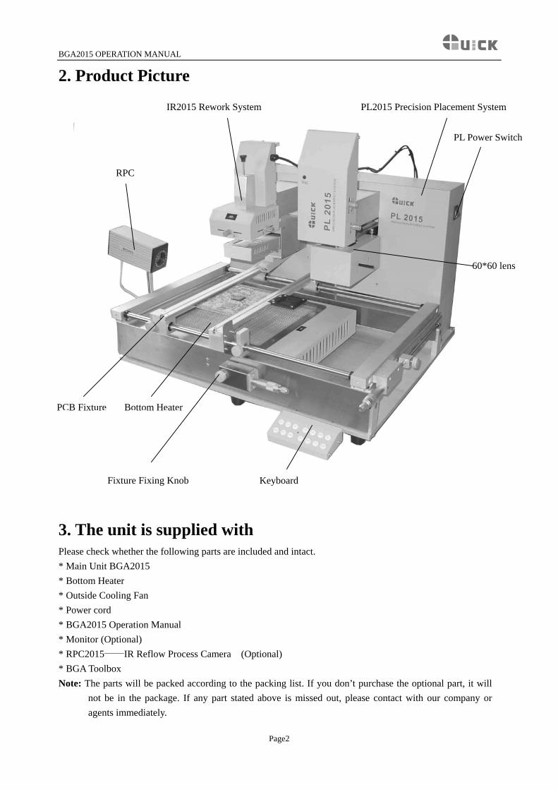
2. Product Picture
IR2015 Rework System PL2015 Precision Placement System
RPC
60*60 lens
PL Power Switch
PCB Fixture Bottom Heater
Fixture Fixing Knob Keyboard
3. The unit is supplied with
Please check whether the following parts are included and intact. * Main Unit BGA2015 * Bottom Heater * Outside Cooling Fan * Power cord * BGA2015 Operation Manual * Monitor (Optional) * RPC2015——IR Reflow Process Camera (Optional) * BGA Toolbox Note: The parts will be packed according to the packing list. If you don’t purchase the optional part, it will
not be in the package. If any part stated above is missed out, please contact with our company or agents immediately.
Page2
BGA2015 OPERATION MANUAL
4. Safety Instructions Note: For safety of system and operator, please read this manual carefully before operating the unit. Please note that the unit is suitable for soldering and de-soldering of electronic components.
Note: Top and bottom IR radiator will be very hot during working, so explosive and combustible object or
gas and solvent is strictly prohibited in working areas, also please don’ touch the hot housing parts
Note: The laser alignment device includes a secondary laser device, so don’t see the laser bean directly.
Note: When the system happens trouble and needs maintenance, it should be carried on by a experienced
and authorized technician or expert, or contact with service agent and factory. The unit with dangerous voltage! The inexperienced work is dangerous for operators.
5. Specifications and Technical Parameters
5.1 Specifications IR System 1.General Power 2400W (Max) 2.Power of Bottom Heater 1600W (4*400W Infrared ceramic heating tube) 3.Power of Top Heater 720W (4*180W Infrared heating tube, Size: 60×60mm) 2~8µm Approx 4.Preheating Time of Bottom Heater 90s Approx (Size: 267×280mm) 5.Adjusting Range of Top Heater 20~60mm 6.Heating time of Top Heater Approx 10s (From room Temperature to 230℃) 7.Vacuum Pump 12V/300mA, 0.05Mpa 8.Top cooling Fan 12V/300mA 15CFM 9.Laser Alignment Tube 3V/30mA (2 pcs) 10.LCD Display Screen Size: 65.7×23.5 (mm) 16×2 character 11.Communication Standard RS-232C (Connect with PC) 12.Movable Motor 24VDC/100mA 13.Movable Arm Range 93mm 14.Infrared Temperature sensor 0~300℃ (Testing range) 15.Outside K Type Sensor Optional 17.Max PCB Size 400mm*440 mm 18.Fuse 20A (220V) PL System 1.Power Appro.15 W 2.Camera 12V/300mA
Magnification: 22×10 times Page3
BGA2015 OPERATION MANUAL
Horizontal resolution: 480 TV lines PAL format (composite)
3.Vacuum Pump: 12V/600mA, 0.05Mpa (Max) 4.LED lighting: White LED (lower side), Red LED (upper side) (with adjustable brightness) 5.Movable Arm Range: 93mm 6.Movable Motor: 24VDC/100mA 7.Fuse: 1A (110V), 0.5A (220V) 8.Dimension: 640*540*410 (mm) 9.Camera output signal is video signal 10.The operation of Camera on PL and IR alternates according to the movement of PL’s telescopic arm.
Brightness of IR camera is controlled by keyboard of PL. 11. Net weight: 58kg 12. Packaging dimension: 970*830*520(mm)
Note: When purchasing the equipment, please indicate the working voltage.
5.2 Technical Parameters TL: Melting temperature of solder T1: Heat preservation starting temperature of reflow soldering T2: Heat preservation ending temperature of reflow soldering T3: Peak value temperature of soldering and de-soldering T0: Valve temperature: The lowest temperature of Bottom Heater when Top Heater heats up. T0<TB TB: The set temperature of bottom heater Tb: The real time temperature value of Bottom Heater TC: The real time temperature value of Top Heater S1: Heating time rising from T1 to T2 S2: Heating time rising from T2 to T3 S3: Heat preservation time of T3 IR 2015 Rework System has ten working modes and its parameter can be changed according to demand. Concrete setting as the following: 0. T1=100℃ S1=60s T2=140℃ S2=40s T3=200℃ S3=10s TL=183℃ TB=130℃ T0=60℃ 1. T1=110℃ S1=60s T2=150℃ S2=30s T3=200℃ S3=10s TL=183℃ TB=140℃ T0=90℃ 2. T1=120℃ S1=70s T2=160℃ S2=25s T3=200℃ S3=10s TL=183℃ TB=150℃ T0=90℃ 3. T1=120℃ S1=70s T2=160℃ S2=30s T3=205℃ S3=10s TL=183℃ TB=160℃ T0=100℃ 4. T1=130℃ S1=60s T2=165℃ S2=25s T3=200℃ S3=10s TL=183℃ TB=170℃ T0=90℃ 5. T1=110℃ S1=50s T2=150℃ S2=30s T3=200℃ S3=10s TL=183℃ TB=150℃ T0=60℃ 6. T1=120℃ S1=40s T2=150℃ S2=30s T3=195℃ S3=10s TL=183℃ TB=160℃ T0=60℃ 7. T1=120℃ S1=40s T2=160℃ S2=30s T3=205℃ S3=10s TL=183℃ TB=170℃ T0=90℃ 8. T1=130℃ S1=50s T2=165℃ S2=30s T3=210℃ S3=10s TL=183℃ TB=170℃ T0=90℃ 9. T1=100℃ S1=40s T2=140℃ S2=40s T3=200℃ S3=10s TL=183℃ TB=150℃ T0=90℃
Page4
BGA2015 OPERATION MANUAL
6. Install and Connect System
6.1 Place System
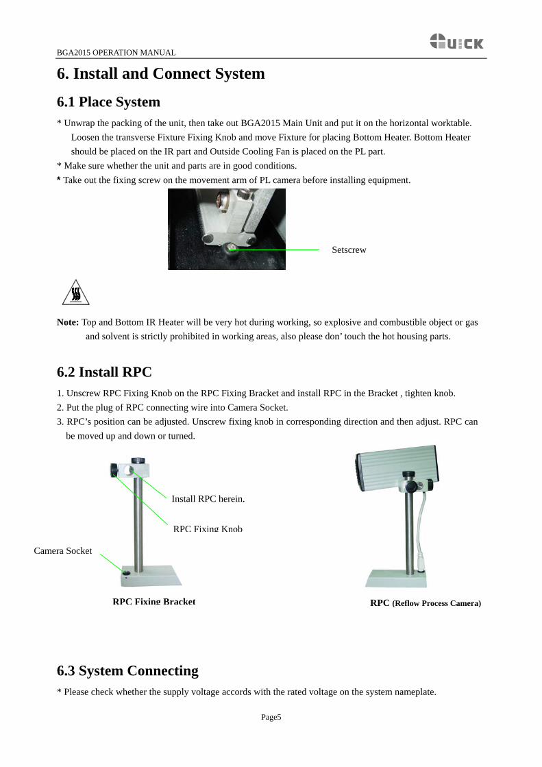
* Unwrap the packing of the unit, then take out BGA2015 Main Unit and put it on the horizontal worktable. Loosen the transverse Fixture Fixing Knob and move Fixture for placing Bottom Heater. Bottom Heater should be placed on the IR part and Outside Cooling Fan is placed on the PL part.
* Make sure whether the unit and parts are in good conditions. * Take out the fixing screw on the movement arm of PL camera before installing equipment.
Setscrew
Note: Top and Bottom IR Heater will be very hot during working, so explosive and combustible object or gas and solvent is strictly prohibited in working areas, also please don’ touch the hot housing parts.
6.2 Install RPC 1. Unscrew RPC Fixing Knob on the RPC Fixing Bracket and install RPC in the Bracket , tighten knob. 2. Put the plug of RPC connecting wire into Camera Socket. 3. RPC’s position can be adjusted. Unscrew fixing knob in corresponding direction and then adjust. RPC can
be moved up and down or turned.
Install RPC herein.
RPC Fixing Knob
Camera Socket
RPC Fixing Bracket RPC (Reflow Process Camera)
6.3 System Connecting * Please check whether the supply voltage accords with the rated voltage on the system nameplate.
Page5
BGA2015 OPERATION MANUAL
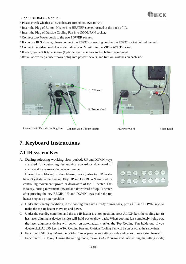
* Please check whether all switches are turned off. (Set to “0”) * Insert the Plug of Bottom Heater into HEATER socket located at the back of IR. * Insert the Plug of Outside Cooling Fan into COOL FAN socket. * Connect two Power cords to the two POWER sockets. * If you use IR Software, please connect the RS232 connecting cord to the RS232 socket behind the unit. * Connect the video cord of outside Indicator or Monitor to the VIDEO-OUT socket. * If need, connect K type sensor (Optional) to the sensor socket behind equipment. After all above steps, insert power plug into power sockets, and turn on switches on each side.
IR Power Cord
RS232 cord
Connect with Outside Cooling Fan Connect with Bottom Heater PL Power Cord Video Lead
7. Keyboard Instructions
7.1 IR system Key
Page6
A. During selecting working flow period, UP and DOWN keysare used for controlling the moving upward or downward ofcursor and increase or decrease of number.
During the soldering or de-soldering period, also top IR heaterhaven’t yet started to heat up, key UP and key DOWN are used forcontrolling movement upward or downward of top IR heater. Thatis to say, during movement upward and downward of top IR heater,after pressing the key BEGIN, UP and DOWN keys make the topheater stop at a proper position
B. Under the standby condition, if the cooling fan have already drawn back, press UP and DOWN keys to make the top IR heater move up and down.
C. Under the standby condition and the top IR heater is at top position, press ALIGN key, the cooling fan (it has laser alignment device inside) will hold out or draw back. When cooling fan completely holds out, the laser alignment device will switch on automatically. After the Top Cooling Fan holds out, if you double click ALIGN key, the Top Cooling Fan and Outside Cooling Fan will be on or off at the same time.
D. Function of SET key: Make the BGA-IR enter parameters setting mode and cursor move a step forward. E. Function of EXIT key: During the setting mode, make BGA-IR cursor exit until exiting the setting mode;
BGA2015 OPERATION MANUAL
Page7
During the soldering or de-soldering period, make BGA-IR exit operation. F. Function of BEGIN key: During the standby condition, make BGA-IR get into soldering or de-soldering
situation. G. Function of CAL Key: During the soldering or de-soldering process, when the temperature increase from
T2 to T3, press this key, the current temperature will multiply a coefficient to make TC=TL, calibrating TL. After the flow has finished and come back to initialization, it will save the coefficient. (CAL key is in the CAL hole.)
Note: If press CAL Key again in the initialization situation, the temperature calibration coefficient of TL comes back to system initialization “1”.
7.2 PL system Key A. When PL camera is pulled out, keyboard only controls PL camera and its lighting. PL-head’s (placement
head) upward and downward movement is forbidden. Key UP and key DOWN are useless. B. When PL camera is retracted inside, keyboard only controls RPC and its lighting. PL-head’s upward and
downward movement is allowed. Key UP and key DOWN can control upward and downward movements of PL-HEAD.
C. When PL camera is pulled out, press BOTTOM and UP keys simultaneously to increase the brightness of PL bottom light, press BOTTOM and DOWN keys simultaneously to decrease the brightness of PL bottom light; press TOP and UP keys simultaneously to increase the brightness of PL top light, press TOP and DOWN keys simultaneously to decrease the brightness of PL top light.
D. When PL camera is retracted inside, press BOTTOM or TOP plus UP keys simultaneously to increase the brightness of RPC light, press BOTTOM or TOP plus DOWN keys simultaneously to decrease the brightness of RPC light
E. ZOOM+ and ZOOM- keys are used for controlling zoom of image. F. FOCUS+ and FOCUS- are for the camera focusing purpose. G. UP and DOWN key are used for controlling upward and downward movement of PL-HEAD.
8. IR System Operation
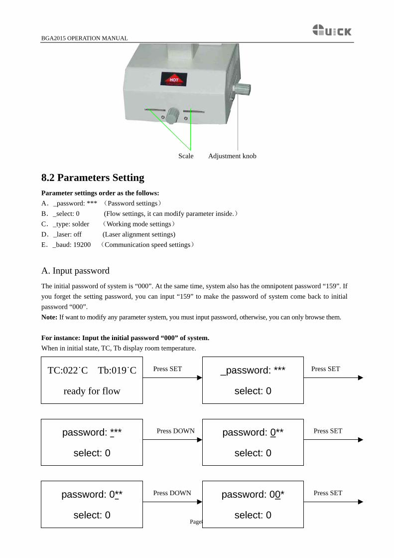
8.1 Part Function * Adjust the Aperture System The Aperture System of Top Radiator can be adjust from 20×20 (mm) to 60×60 (mm) by two Adjustment Knobs. Unscrew the knobs before adjusting, and adjust the window size, then tighten knobs. The scale “2” on the housing means 20mm and “3’ means 30mm, other scale is similar. For example, if you want to adjust size to 50×50(mm), adjust two knobs to the scale of “5” and tighten them. Note: Adjusting the aperture system can protect the adjacent components on the PCB from being heated. But, when the aperture system is adjusted to small size, the Top Radiator will be very hot and decrease its lifetime, so it’s necessary to increase the window size appropriately to avoid the damage of the Top Radiator.
BGA2015 OPERATION MANUAL
Scale Adjustment knob
8.2 Parameters Setting Parameter settings order as the follows: A._password: *** (Password settings) B._select: 0 (Flow settings, it can modify parameter inside.) C._type: solder (Working mode settings) D._laser: off (Laser alignment settings) E._baud: 19200 (Communication speed settings)
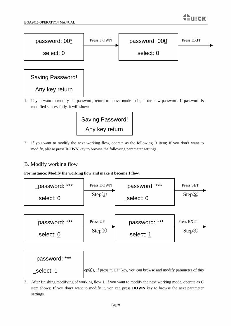
A. Input password The initial password of system is “000”. At the same time, system also has the omnipotent password “159”. If you forget the setting password, you can input “159” to make the password of system come back to initial password “000”. Note: If want to modify any parameter system, you must input password, otherwise, you can only browse them. For instance: Input the initial password “000” of system. When in initial state, TC, Tb display room temperature. Press SET Press SET
_password: ***
select: 0
TC:022˙C Tb:019˙C
ready for flow
Press DOWN Press SET
password: ***
select: 0
password: 0**
select: 0
Press DOWN Press SET
Page8
password: 00*
select: 0
password: 0**
select: 0
BGA2015 OPERATION MANUAL
Press DOWN Press EXIT
password: 000
select: 0
password: 00*
select: 0
Finish password inputting:
Saving Password!
Any key return
1. If you want to modify the password, return to above mode to input the new password. If password is modified successfully, it will show:
Saving Password!
Any key return
2. If you want to modify the next working flow, operate as the following B item; If you don’t want to
modify, please press DOWN key to browse the following parameter settings.
B. Modify working flow For instance: Modify the working flow and make it become 1 flow. Press DOWN Press SET
Step① Step②
Press UP Press EXIT
Step③ Step④
password: ***
select: 0
password: ***
select: 0
password: ***
select: 0
password: ***
select: 1
1. When carry on the forth step (Step④), if press “SET” key, you can browse and modify parameter of this
flow, shown as C-1 item.
password: ***
select: 1
2. After finishing modifying of working flow 1, if you want to modify the next working mode, operate as C item shows; If you don’t want to modify it, yon can press DOWN key to browse the next parameter settings.
Page9
BGA2015 OPERATION MANUAL
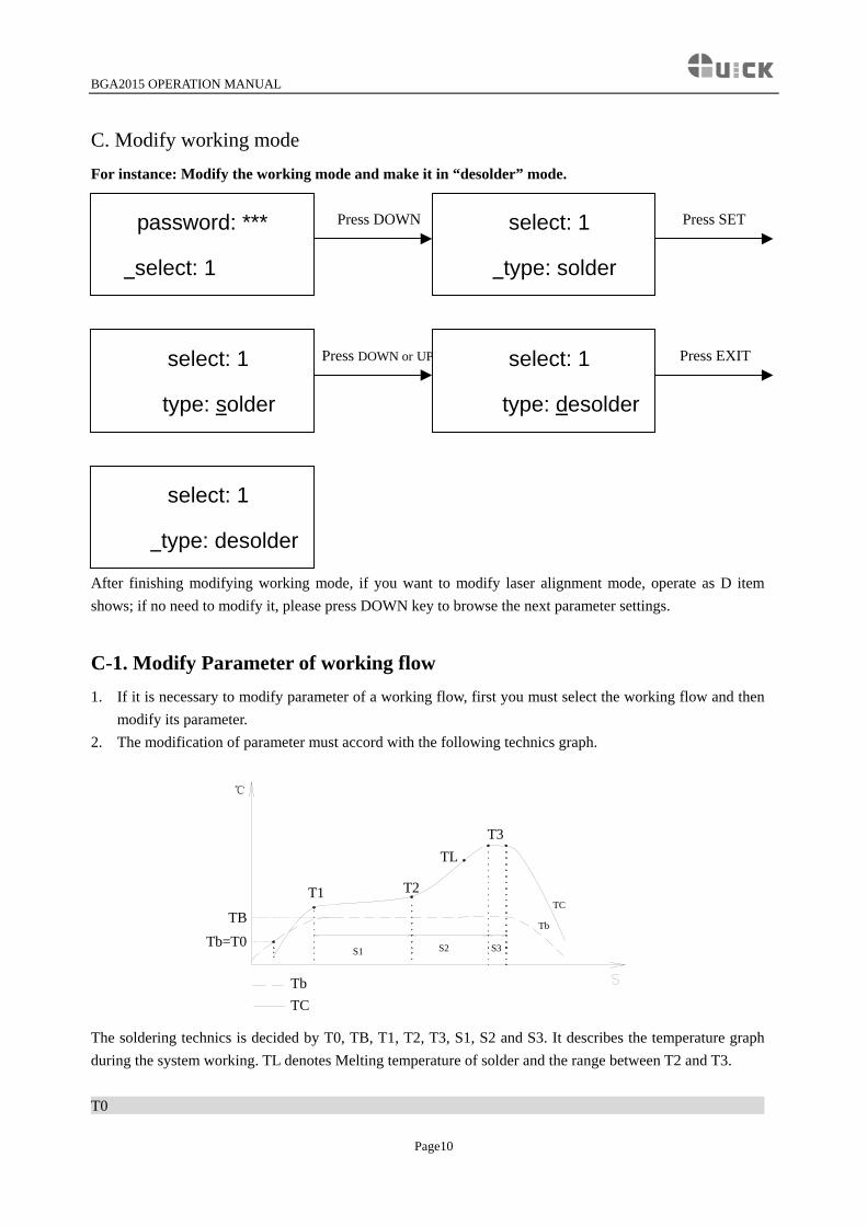
C. Modify working mode
For instance: Modify the working mode and make it in “desolder” mode. Press DOWN Press SET
password: ***
select: 1
select: 1
type: solder
Press DOWN or UP Press EXIT
select: 1
type: desolder
select: 1
type: solder
select: 1
type: desolder
After finishing modifying working mode, if you want to modify laser alignment mode, operate as D item shows; if no need to modify it, please press DOWN key to browse the next parameter settings.
C-1. Modify Parameter of working flow 1. If it is necessary to modify parameter of a working flow, first you must select the working flow and then
modify its parameter. 2. The modification of parameter must accord with the following technics graph.
TB
T3TL
S1
T2T1
℃
Tb=T0 S2 S3
Tb
TC
TbTC
The soldering technics is decided by T0, TB, T1, T2, T3, S1, S2 and S3. It describes the temperature graph during the system working. TL denotes Melting temperature of solder and the range between T2 and T3. T0
Page10
BGA2015 OPERATION MANUAL
Page11
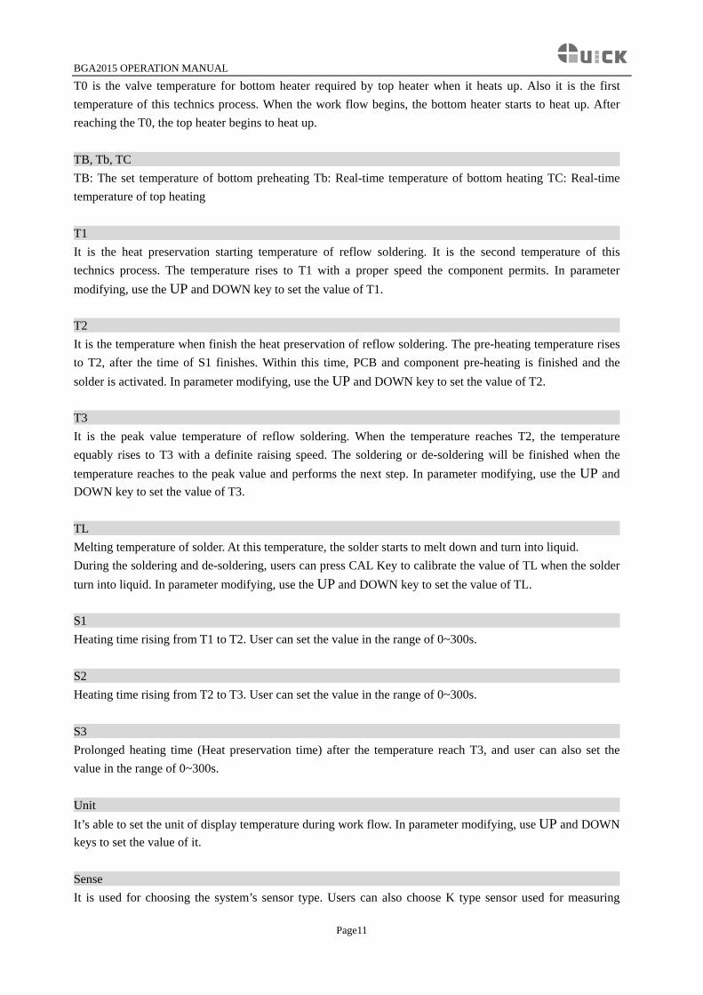
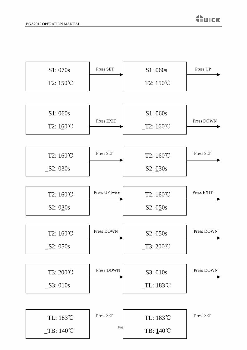
T0 is the valve temperature for bottom heater required by top heater when it heats up. Also it is the first temperature of this technics process. When the work flow begins, the bottom heater starts to heat up. After reaching the T0, the top heater begins to heat up. TB, Tb, TC TB: The set temperature of bottom preheating Tb: Real-time temperature of bottom heating TC: Real-time temperature of top heating T1 It is the heat preservation starting temperature of reflow soldering. It is the second temperature of this technics process. The temperature rises to T1 with a proper speed the component permits. In parameter modifying, use the UP and DOWN key to set the value of T1. T2 It is the temperature when finish the heat preservation of reflow soldering. The pre-heating temperature rises to T2, after the time of S1 finishes. Within this time, PCB and component pre-heating is finished and the solder is activated. In parameter modifying, use the UP and DOWN key to set the value of T2. T3 It is the peak value temperature of reflow soldering. When the temperature reaches T2, the temperature equably rises to T3 with a definite raising speed. The soldering or de-soldering will be finished when the temperature reaches to the peak value and performs the next step. In parameter modifying, use the UP and DOWN key to set the value of T3. TL Melting temperature of solder. At this temperature, the solder starts to melt down and turn into liquid. During the soldering and de-soldering, users can press CAL Key to calibrate the value of TL when the solder turn into liquid. In parameter modifying, use the UP and DOWN key to set the value of TL. S1 Heating time rising from T1 to T2. User can set the value in the range of 0~300s. S2 Heating time rising from T2 to T3. User can set the value in the range of 0~300s. S3 Prolonged heating time (Heat preservation time) after the temperature reach T3, and user can also set the value in the range of 0~300s. Unit It’s able to set the unit of display temperature during work flow. In parameter modifying, use UP and DOWN keys to set the value of it. Sense It is used for choosing the system’s sensor type. Users can also choose K type sensor used for measuring
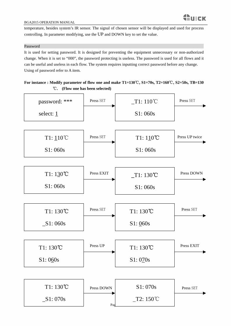
BGA2015 OPERATION MANUAL
temperature, besides system’s IR sensor. The signal of chosen sensor will be displayed and used for process controlling. In parameter modifying, use the UP and DOWN key to set the value. Password It is used for setting password. It is designed for preventing the equipment unnecessary or non-authorized change. When it is set to “000”, the password protecting is useless. The password is used for all flows and it can be useful and useless in each flow. The system requires inputting correct password before any change. Using of password refer to A item. For instance : Modify parameter of flow one and make T1=130℃, S1=70s, T2=160℃, S2=50s, TB=130
℃. (Flow one has been selected)
Press SET Press SET
password: ***
select: 1
_T1: 110℃
S1: 060s
Press SET Press UP twice
T1: 110℃
S1: 060s
T1: 110℃
S1: 060s
Press EXIT Press DOWN
_T1: 130℃
S1: 060s
T1: 130℃
S1: 060s
Press SET Press SET
T1: 130℃
S1: 060s
T1: 130℃
_S1: 060s
Press UP Press EXIT
T1: 130℃
S1: 060s
T1: 130℃
S1: 070s
Press DOWN Press SET
Page12
T1: 130℃
S1: 070s
S1: 070s
T2: 150℃
BGA2015 OPERATION MANUAL
Press SET Press UP
S1: 060s
T2: 150℃
S1: 070s
T2: 150℃
Press EXIT Press DOWN
S1: 060s
T2: 160℃
S1: 060s
T2: 160℃
Press SET Press SET
T2: 160℃
S2: 030s
T2: 160℃
S2: 030s
Press UP twice Press EXIT
T2: 160℃
S2: 050s
T2: 160℃
S2: 030s
Press DOWN Press DOWN
S2: 050s
T3: 200℃
T2: 160℃
S2: 050s
Press DOWN Press DOWN
S3: 010s
TL: 183℃
T3: 200℃
S3: 010s
Press SET Press SET TL: 183℃
TB: 140℃ Page13
TL: 183℃
TB: 140℃
BGA2015 OPERATION MANUAL
Press DOWN Press EXIT
TL: 183℃
TB: 130℃
TL: 183℃
TB: 140℃
Press DOWN Press DOWN
TB: 130℃
T0: 090℃
TL: 183℃
TB: 130℃
Press DOWN Press DOWN
unit:℃
sense: IR
T0: 090℃
unit:℃
sense: IR
type: desolder
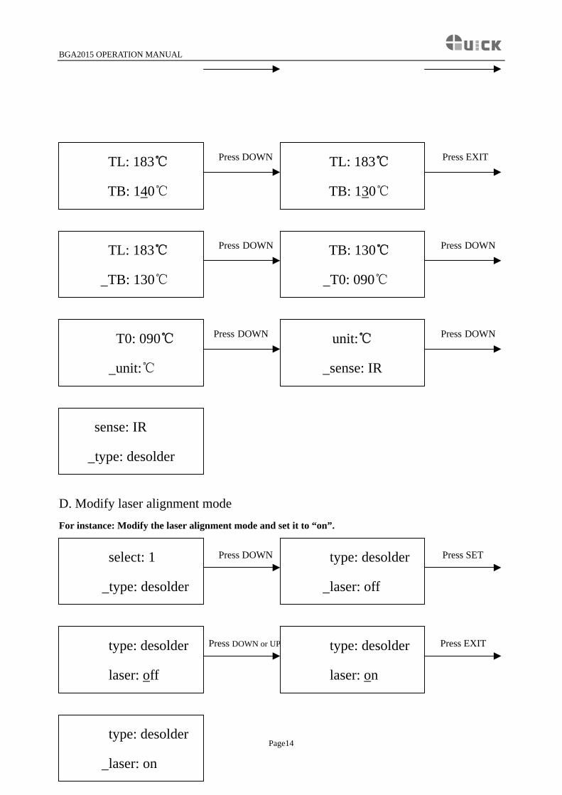
D. Modify laser alignment mode For instance: Modify the laser alignment mode and set it to “on”. Press DOWN Press SET
type: desolder
laser: off
select: 1
type: desolder
Press DOWN or UP Press EXIT
type: desolder
laser: on
type: desolder
laser: off
type: desolder
laser: on Page14
BGA2015 OPERATION MANUAL
1. After finishing the modification, the next step communication speed, will not be able modified by
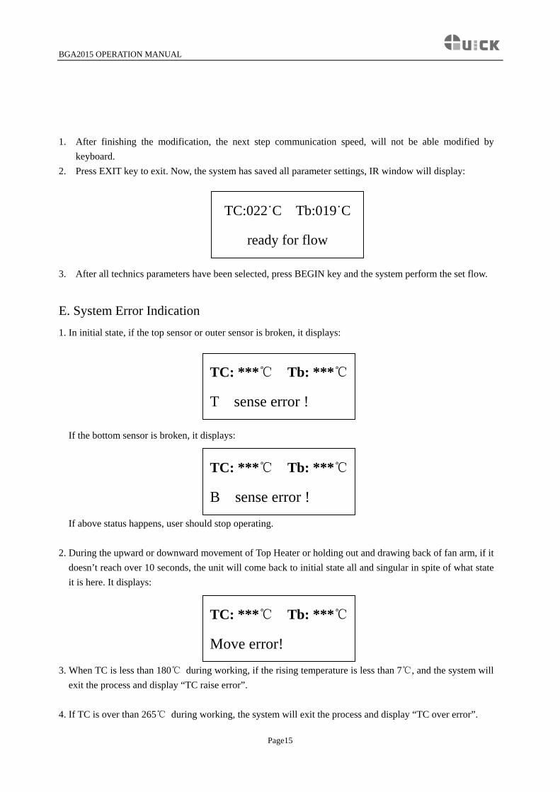
keyboard. 2. Press EXIT key to exit. Now, the system has saved all parameter settings, IR window will display:
TC:022˙C Tb:019˙C
ready for flow
3. After all technics parameters have been selected, press BEGIN key and the system perform the set flow.
E. System Error Indication
1. In initial state, if the top sensor or outer sensor is broken, it displays:
TC: ***℃ Tb: ***℃
T sense error !
If the bottom sensor is broken, it displays:
TC: ***℃ Tb: ***℃
B sense error !
If above status happens, user should stop operating.
2. During the upward or downward movement of Top Heater or holding out and drawing back of fan arm, if it doesn’t reach over 10 seconds, the unit will come back to initial state all and singular in spite of what state it is here. It displays:
TC: ***℃ Tb: ***℃
Move error!
3. When TC is less than 180℃ during working, if the rising temperature is less than 7℃, and the system will
exit the process and display “TC raise error”. 4. If TC is over than 265℃ during working, the system will exit the process and display “TC over error”.
Page15
BGA2015 OPERATION MANUAL
8.3 Operating technics instruction
Note: Top and Bottom Heater will be very hot during working, so please don’ touch the hot housing parts.
Note: The laser alignment device includes a secondary laser device, so don’t see the laser bean directly.
Soldering Technics (System’s power has been switched on) 1. Turn on power switch of each part. 2. Move PCB Fixture with fixed PCB and make it above the Bottom Radiator and make the soldered
component on the PCB between Top Radiator and Bottom Radiator. The position is easy to be measured with laser alignment device. The right position should make the red laser point in the center of component.
3. Adjust aperture system, and get a proper window size. 4. Adjust RPC in appropriate place, adjust size and focus of image with PL keyboard to display component
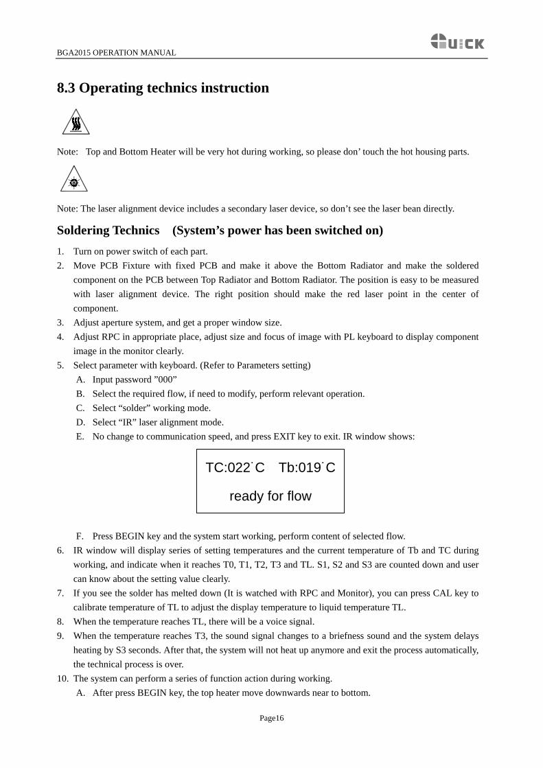
image in the monitor clearly. 5. Select parameter with keyboard. (Refer to Parameters setting)
A. Input password ”000” B. Select the required flow, if need to modify, perform relevant operation. C. Select “solder” working mode. D. Select “IR” laser alignment mode. E. No change to communication speed, and press EXIT key to exit. IR window shows:
TC:022˙C Tb:019˙C
ready for flow
F. Press BEGIN key and the system start working, perform content of selected flow. 6. IR window will display series of setting temperatures and the current temperature of Tb and TC during
working, and indicate when it reaches T0, T1, T2, T3 and TL. S1, S2 and S3 are counted down and user can know about the setting value clearly.
7. If you see the solder has melted down (It is watched with RPC and Monitor), you can press CAL key to calibrate temperature of TL to adjust the display temperature to liquid temperature TL.
8. When the temperature reaches TL, there will be a voice signal. 9. When the temperature reaches T3, the sound signal changes to a briefness sound and the system delays
heating by S3 seconds. After that, the system will not heat up anymore and exit the process automatically, the technical process is over.
10. The system can perform a series of function action during working. A. After press BEGIN key, the top heater move downwards near to bottom.
Page16
BGA2015 OPERATION MANUAL
B. After the system sounds unvaryingly, the top heater move upwards and Top Cooling Fan and Outside Cooling Fan spread out to blow cooling air simultaneously.
C. After 150 seconds, the two Cooling Fns stop blowing, and the soldering technics has been finished.
De-soldering Technics (System’s power has been switched on) 1. Turn on power switch of each part. 2. Fix the PCB on the top of Bottom Heater and make the de-soldered component between Top Heater and
Bottom Heater. The position is easy to be measured with laser alignment device. The right position should make the red laser point in the center of component and the suction pad in center of component also.
3. Press the vacuum suction tube to check whether suction pad is in the center of component. (If the deflection is too much, the tube will not be able to pick up the component.
4. Adjust aperture system, and get a proper window size. 5. Adjust RPC in appropriate place, adjust size and focus of image with PL keyboard to display component
image in the monitor clearly. 6. Select parameter with keyboard. (Refer to Parameters setting)
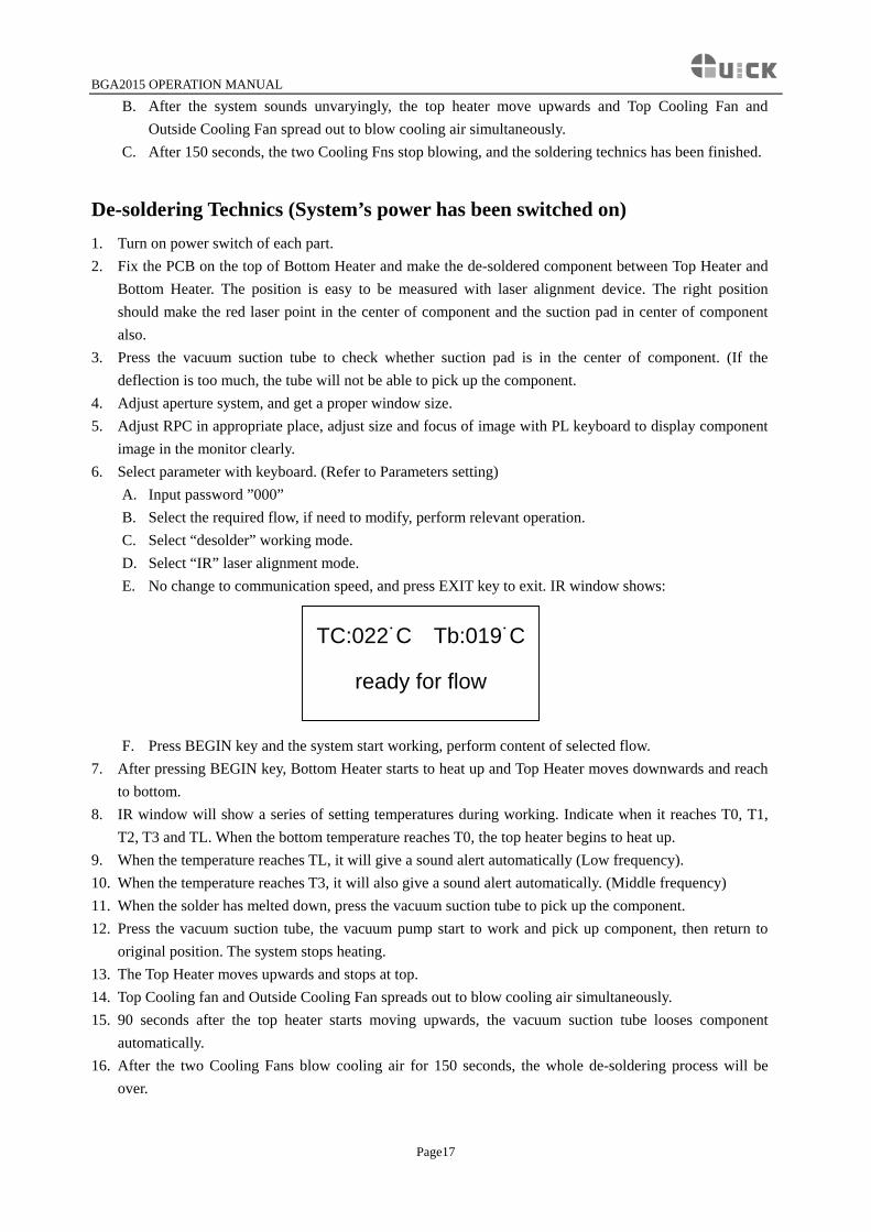
A. Input password ”000” B. Select the required flow, if need to modify, perform relevant operation. C. Select “desolder” working mode. D. Select “IR” laser alignment mode. E. No change to communication speed, and press EXIT key to exit. IR window shows:
TC:022˙C Tb:019˙C
ready for flow
F. Press BEGIN key and the system start working, perform content of selected flow. 7. After pressing BEGIN key, Bottom Heater starts to heat up and Top Heater moves downwards and reach
to bottom. 8. IR window will show a series of setting temperatures during working. Indicate when it reaches T0, T1,
T2, T3 and TL. When the bottom temperature reaches T0, the top heater begins to heat up. 9. When the temperature reaches TL, it will give a sound alert automatically (Low frequency). 10. When the temperature reaches T3, it will also give a sound alert automatically. (Middle frequency) 11. When the solder has melted down, press the vacuum suction tube to pick up the component. 12. Press the vacuum suction tube, the vacuum pump start to work and pick up component, then return to
original position. The system stops heating. 13. The Top Heater moves upwards and stops at top. 14. Top Cooling fan and Outside Cooling Fan spreads out to blow cooling air simultaneously. 15. 90 seconds after the top heater starts moving upwards, the vacuum suction tube looses component
automatically. 16. After the two Cooling Fans blow cooling air for 150 seconds, the whole de-soldering process will be
over.
Page17
BGA2015 OPERATION MANUAL
9. PL System Operation
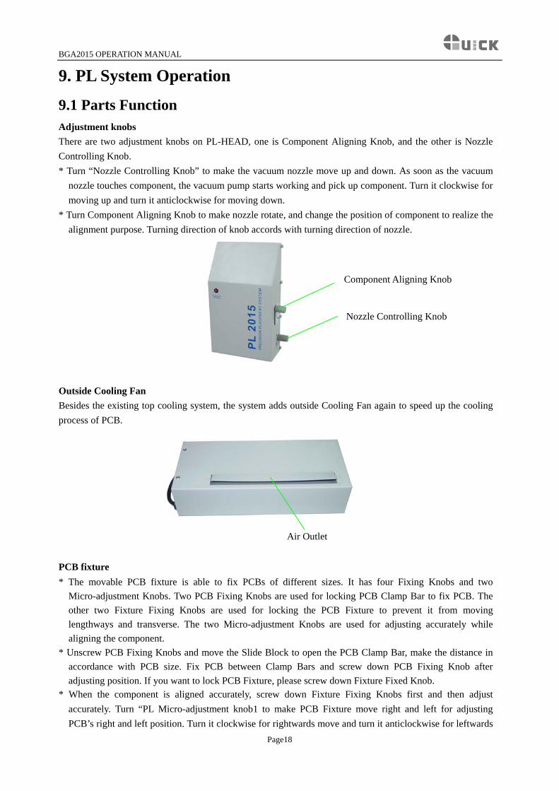
9.1 Parts Function Adjustment knobs There are two adjustment knobs on PL-HEAD, one is Component Aligning Knob, and the other is Nozzle Controlling Knob. * Turn “Nozzle Controlling Knob” to make the vacuum nozzle move up and down. As soon as the vacuum
nozzle touches component, the vacuum pump starts working and pick up component. Turn it clockwise for moving up and turn it anticlockwise for moving down.
* Turn Component Aligning Knob to make nozzle rotate, and change the position of component to realize the alignment purpose. Turning direction of knob accords with turning direction of nozzle.
Component Aligning Knob
Nozzle Controlling Knob
Outside Cooling Fan Besides the existing top cooling system, the system adds outside Cooling Fan again to speed up the cooling process of PCB.
Air Outlet
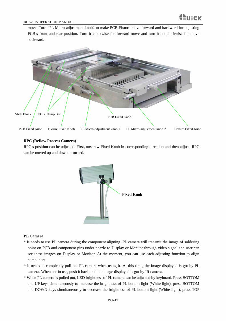
PCB fixture * The movable PCB fixture is able to fix PCBs of different sizes. It has four Fixing Knobs and two
Micro-adjustment Knobs. Two PCB Fixing Knobs are used for locking PCB Clamp Bar to fix PCB. The other two Fixture Fixing Knobs are used for locking the PCB Fixture to prevent it from moving lengthways and transverse. The two Micro-adjustment Knobs are used for adjusting accurately while aligning the component.
* Unscrew PCB Fixing Knobs and move the Slide Block to open the PCB Clamp Bar, make the distance in accordance with PCB size. Fix PCB between Clamp Bars and screw down PCB Fixing Knob after adjusting position. If you want to lock PCB Fixture, please screw down Fixture Fixed Knob.
* When the component is aligned accurately, screw down Fixture Fixing Knobs first and then adjust accurately. Turn “PL Micro-adjustment knob1 to make PCB Fixture move right and left for adjusting PCB’s right and left position. Turn it clockwise for rightwards move and turn it anticlockwise for leftwards
Page18
BGA2015 OPERATION MANUAL
move. Turn “PL Micro-adjustment knob2 to make PCB Fixture move forward and backward for adjusting PCB’s front and rear position. Turn it clockwise for forward move and turn it anticlockwise for move backward.
Slide Block PCB Clamp Bar PCB Fixed Knob
Fixture Fixed Knob Fixture Fixed KnobPCB Fixed Knob PL Micro-adjustment knob 1 PL Micro-adjustment knob 2
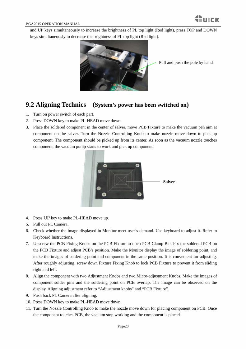
RPC (Reflow Process Camera) RPC’s position can be adjusted. First, unscrew Fixed Knob in corresponding direction and then adjust. RPC can be moved up and down or turned.
Fixed Knob
PL Camera * It needs to use PL camera during the component aligning. PL camera will transmit the image of soldering
point on PCB and component pins under nozzle to Display or Monitor through video signal and user can see these images on Display or Monitor. At the moment, you can use each adjusting function to align component.
* It needs to completely pull out PL camera when using it. At this time, the image displayed is got by PL camera. When not in use, push it back, and the image displayed is got by IR camera.
* When PL camera is pulled out, LED brightness of PL camera can be adjusted by keyboard. Press BOTTOM and UP keys simultaneously to increase the brightness of PL bottom light (White light), press BOTTOM and DOWN keys simultaneously to decrease the brightness of PL bottom light (White light), press TOP
Page19
BGA2015 OPERATION MANUAL
and UP keys simultaneously to increase the brightness of PL top light (Red light), press TOP and DOWN keys simultaneously to decrease the brightness of PL top light (Red light).
Pull and push the pole by hand
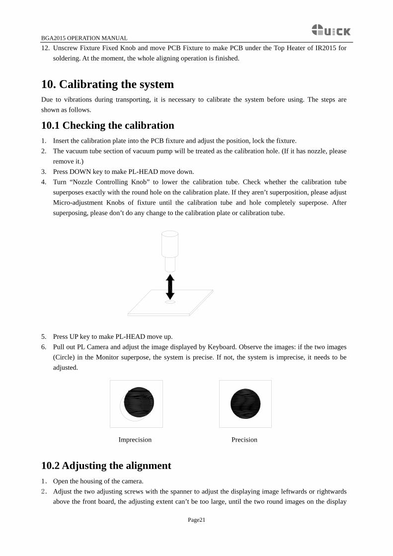
9.2 Aligning Technics (System’s power has been switched on) 1. Turn on power switch of each part. 2. Press DOWN key to make PL-HEAD move down. 3. Place the soldered component in the center of salver, move PCB Fixture to make the vacuum pen aim at
component on the salver. Turn the Nozzle Controlling Knob to make nozzle move down to pick up component. The component should be picked up from its center. As soon as the vacuum nozzle touches component, the vacuum pump starts to work and pick up component.
Salver
4. Press UP key to make PL-HEAD move up. 5. Pull out PL Camera. 6. Check whether the image displayed in Monitor meet user’s demand. Use keyboard to adjust it. Refer to
Keyboard Instructions. 7. Unscrew the PCB Fixing Knobs on the PCB Fixture to open PCB Clamp Bar. Fix the soldered PCB on
the PCB Fixture and adjust PCB’s position. Make the Monitor display the image of soldering point, and make the images of soldering point and component in the same position. It is convenient for adjusting. After roughly adjusting, screw down Fixture Fixing Knob to lock PCB Fixture to prevent it from sliding right and left.
8. Align the component with two Adjustment Knobs and two Micro-adjustment Knobs. Make the images of component solder pins and the soldering point on PCB overlap. The image can be observed on the display. Aligning adjustment refer to “Adjustment knobs” and “PCB Fixture”.
9. Push back PL Camera after aligning. 10. Press DOWN key to make PL-HEAD move down. 11. Turn the Nozzle Controlling Knob to make the nozzle move down for placing component on PCB. Once
the component touches PCB, the vacuum stop working and the component is placed.
Page20
BGA2015 OPERATION MANUAL
12. Unscrew Fixture Fixed Knob and move PCB Fixture to make PCB under the Top Heater of IR2015 for soldering. At the moment, the whole aligning operation is finished.
10. Calibrating the system Due to vibrations during transporting, it is necessary to calibrate the system before using. The steps are shown as follows.
10.1 Checking the calibration 1. Insert the calibration plate into the PCB fixture and adjust the position, lock the fixture. 2. The vacuum tube section of vacuum pump will be treated as the calibration hole. (If it has nozzle, please
remove it.) 3. Press DOWN key to make PL-HEAD move down. 4. Turn “Nozzle Controlling Knob” to lower the calibration tube. Check whether the calibration tube
superposes exactly with the round hole on the calibration plate. If they aren’t superposition, please adjust Micro-adjustment Knobs of fixture until the calibration tube and hole completely superpose. After superposing, please don’t do any change to the calibration plate or calibration tube.
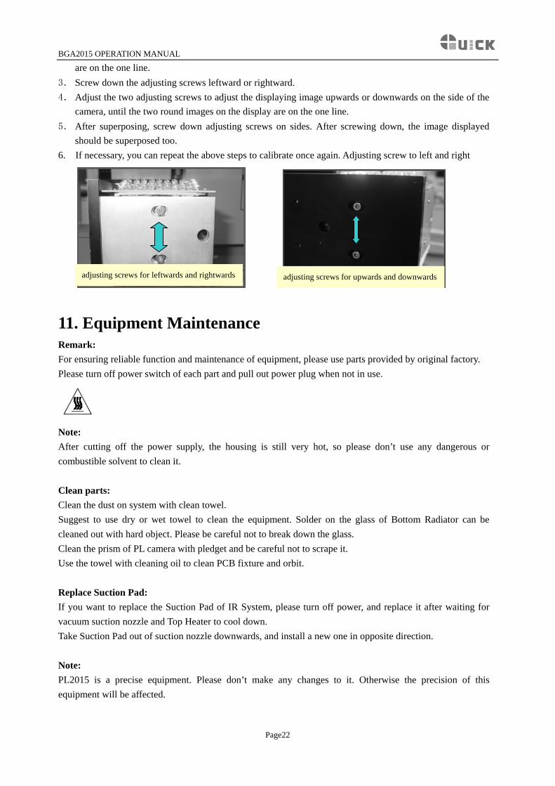
5. Press UP key to make PL-HEAD move up. 6. Pull out PL Camera and adjust the image displayed by Keyboard. Observe the images: if the two images
(Circle) in the Monitor superpose, the system is precise. If not, the system is imprecise, it needs to be adjusted.
Imprecision Precision
10.2 Adjusting the alignment 1. Open the housing of the camera. 2. Adjust the two adjusting screws with the spanner to adjust the displaying image leftwards or rightwards
above the front board, the adjusting extent can’t be too large, until the two round images on the display
Page21
BGA2015 OPERATION MANUAL
are on the one line. 3. Screw down the adjusting screws leftward or rightward. 4. Adjust the two adjusting screws to adjust the displaying image upwards or downwards on the side of the
camera, until the two round images on the display are on the one line. 5. After superposing, screw down adjusting screws on sides. After screwing down, the image displayed
should be superposed too. 6. If necessary, you can repeat the above steps to calibrate once again. Adjusting screw to left and right
adjusting screws for leftwards and rightwards adjusting screws for upwards and downwards
11. Equipment Maintenance Remark: For ensuring reliable function and maintenance of equipment, please use parts provided by original factory. Please turn off power switch of each part and pull out power plug when not in use.
Note: After cutting off the power supply, the housing is still very hot, so please don’t use any dangerous or combustible solvent to clean it. Clean parts: Clean the dust on system with clean towel. Suggest to use dry or wet towel to clean the equipment. Solder on the glass of Bottom Radiator can be cleaned out with hard object. Please be careful not to break down the glass. Clean the prism of PL camera with pledget and be careful not to scrape it. Use the towel with cleaning oil to clean PCB fixture and orbit. Replace Suction Pad: If you want to replace the Suction Pad of IR System, please turn off power, and replace it after waiting for vacuum suction nozzle and Top Heater to cool down. Take Suction Pad out of suction nozzle downwards, and install a new one in opposite direction. Note: PL2015 is a precise equipment. Please don’t make any changes to it. Otherwise the precision of this equipment will be affected.
Page22

QUICK ELECTRONIC EQUIPMENT CO., LTD ADD: WUJIN HIGH TECHNOLOY DEVELOPMENT ZONE CHANGZHOU JIANGSU TEL: 0519-5057999 FAX: 0519-6558599 P.C: 213161 http://www.quickchina.com.cn