Embed Size (px)
DESCRIPTION
A complete construction guide for the 6mmFlyRC Quick Build F-22 as designed by Tomas Hellberg.
Citation preview
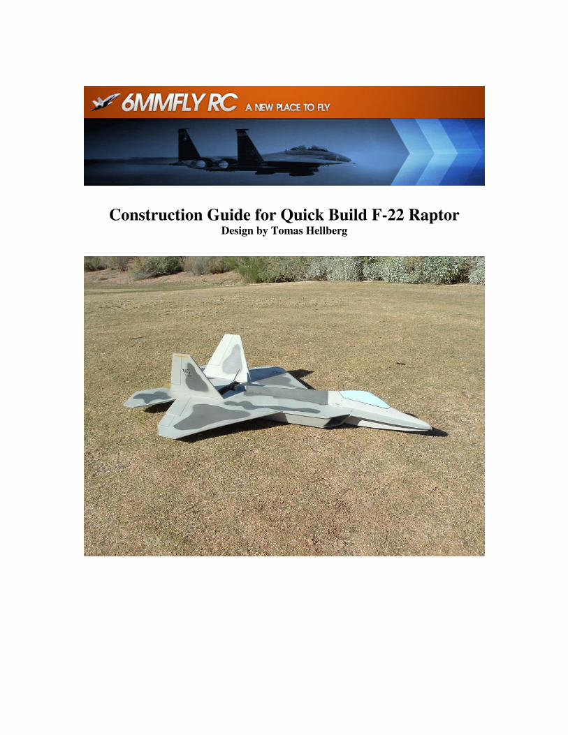
Construction Guide for Quick Build F-22 Raptor Design by Tomas Hellberg

This kit is very simple to put together. The biggest danger in messing up this kit is gluing
the pieces to your work bench. But before you begin, take a couple of minutes to read
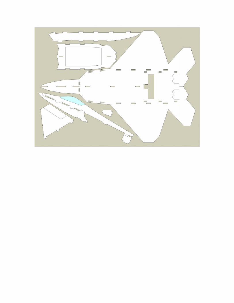
over this entire construction guide as well as the parts in your kit. It’s just a 3D puzzle
with all interlocking pieces. Total construction time is about 2 hours and then you can
take as much time on your finishing as you want.
Glue: We recommend using 5 minute epoxy for gluing in the carbon fiber wing spar and
UHU Creativ glue for foam for just about every other joint. But you can use 5 minute
epoxy on the entire plane and it really won’t make a big difference. For a real quick
build, you could even use hot glue on everything but the carbon spar, but we think that is
not a great option. One more thing: we recommend you dry build you entire plane using
some tape to hold everything together. It lets you see how things fit and lets you plan out
your build. Plus, if you are planning on doing any painting, IT MIGHT BE EASIER TO
PAINT IT BEFORE YOU PUT IT TOGETHER.
Last but not least, we want to thank Tomas Hellberg for giving us permission to kit this
awesome design. Now onto the build!
1. The carbon spar. The carbon spar is
important because it gives your plane the
needed strength on the wings to
withstand all the forces of nature. So
take your time on this. Also, this step
has a good chance you could glue the
wing to your workbench. Don’t do this.
It won’t improve the aerodynamics of
your workbench. Use some wax paper,
or some extra tape or just be careful.
Get your wing out, your 5 minute epoxy,
some masking tape and your carbon rod.
NOTE: This picture is a different
wing, but the process is the same.
Next, figure out which side of the wing
will be the top side. Mask over the slot
in your wing using masking tape or
painters tape as shown. NOTE: You
might have to extend the slot a bit with a
sharp hobby knife.
Then flip the wing over, mask on either
side of the slot to prevent excess epoxy
from getting all over your wing.

Now, mix up a good amount of epoxy
and stir well. The key with epoxy is to
really get it mixed well. So mix it like
crazy. We recommend using a small cup
made of paper or something so you can
bend the lip to make like a little spout,
but any container will do.
Next, and this is important, make sure
your rod is NOT in the slot. The picture
above shows it in the slot but we were
just test fitting the rod. Then pour in the
epoxy the length of the slot and even it
out within the slot. Insert rod and mash
down hard. Wipe away any excess
epoxy that oozes out. It helps if you
have a good piece of card board or
something to use as a squeegee.
Now remember about gluing your wing
to the table? Now is a good time to
check if your tape on the bottom blew a
hole in it and leaked epoxy all over the
place. If so, wipe it up and make sure
you don’t glue the wing down. Can you
tell we have glued our wing down a time
or two? Okay, don’t wait too long, like
5 minutes and remove your tape. That is
pretty much the hardest part, and you are
done!
2. Front fuselage assembly. Next, we
recommend using epoxy for this step
too, it makes the rest of the assembly go
a little quicker if you have a nice rigid
joint here. Mix up a bit of epoxy and
spread on one side of the joint and push
it together. Make sure here not to glue
to the table again. Really, this happens a
lot. NOTE: Below is what your
airplane should look like.

3. Next, let’s get the canopy and forward
lower fuse pieces and connect them. We
used UHU Creativ for foam glue for all
other joints from this point forward
unless noted.
Make sure you attach the canopy (big
piece) to the top of your wing (as
discussed the first steps). Attach the
lower and upper piece through the slots.
4. Bottom Fuse. To prepare to mount
the bottom fuse piece, first locate the
little piece that bridges the gap between
the wing and the bottom fuse. Glue into
place as pictured. You may want to use
epoxy on this small piece, since the
motor mount attaches to it. Next, attach
the bottom fuse piece. It will not be
attached well, as it sort of floats, but
make sure it is centered and on straight.
Doing this first, makes it easier to attach
the intake pieces later.
5. Engine Intakes. Find the two pieces
that make up the engine intakes.
Now because this is an F-22, and
because all the cuts on your kit are at
right angles, this part takes a bit of
patience, and a little trim work on your
part. No big deal. You will need a sharp
hobby knife or razor blade. Sharp being
the key word. If you insert the intakes
pieces into the tabs, you will notice a

considerable gap between the edges of
the intake pieces and the bottom fuse
piece you just attached. This is because
the intake pieces angle inward to meet
up. In order to allow the pieces to tilt
inward, you may have to trim out the
slots in the main body/wing of the
model. We just trimmed the corner on
both sides of the wing to allow the tabs
to better tilt inside the slot. See Picture
below. This step can take a bit of time,
but just take it slow and dry fit each side
using some masking tape or pins. Then
glue up each side, making sure you glue
the intakes sides to both the body/wing
and the bottom fuse piece. This is where
a contact cement like UHU Creativ
comes in handy.
If you flip your plane over, you will
notice the tabs extend through the top of
the slots slightly. Trim or sand as
desired. You can fill in any gaps with
some light weight spackle if you want to
improve the appearance of the aircraft.
6. Front Intakes: This step is very similar
to the side intakes, requiring you to trim
a bit to make them angle correctly.
7. Vertical Tails. The F-22 also has
angled vertical tails that roughly follow
the same angle as the side fuselage
pieces you mounted in step 5.

Insert the tail piece into the slots on the
top of your model and again, trim a bit to
allow some free movement or just work
the foam a bit to achieve an outward
angle, matching the angle of the intakes.
Glue into place. You may want to use
epoxy here as well. It is important to get
the tails at the same angle, though if they
are a little off, it won’t matter much. So
don’t panic.
9. Hatch construction. This is the part
that might take some creativity on your
part. The hatch piece can be attached
about a million different ways. Velcro,
magnets, and good old fashioned duct
tape just to name a few. But you will
need to use some scrap pieces of foam
(included) to let the hatch stay in place.
See below. NOTE: Picture is not of your
plane, but the process is the same.
10. Motor Mount. In you kit you should
have a ply piece and a little foam disk
that match up. Go ahead and laminate
them together with some epoxy. Then,
mount it to the motor area using epoxy.
11. Taileron Prep. You will need to
attach your tailerons next. First you will
need to bevel the edge so the hinge
works properly. See pictures. Using
hinge tape (not provided) or some 3M
scotch tape, attach the ailerons to the
body. You may need to sand these
pieces a bit to make sure they do not rub
on each other in the middle.

Here (below) you can see the beveled
gap in the taileron to allow for free
movement positioned on the bottom of
the plane.
Servo and control horn mounting. This
is all about preference. You can mount
your servos pretty much wherever, but
we prefer under the wing and right over
the CF rod. This gets all the wires inside
the box on the plane and makes it easy.
Study the pictures below. NOTE:
Again, different plane, same process.
12. Connect up your electronics and
paint as desired.

Note on finishing. We coated our entire airplane with some Minwax water based
polyeurathane. It came in a spray can. We did about 2 coats and it worked great. Then
we just used regular spray paint and some masking tape to finish it off. The Minwax
protected the foam from the foam eating regular spray paint. It was like a force field in a
spray can. The bottom line here is test out your paint on some spare foam or only use
foam safe paint. It will melt your airplane if you are not careful.
Recommended Set Up. First, what we mean by recommendation. It’s what we used and
it works well. So you can use a different combo if you like. Also, with just Tailerons,
this plane, and all the Quick Builds perform great, but if you really want to increase
roll rate, add in some ailerons, just tie them directly to the tailerons and you will be
in business.
Rocket
Motor: Grayson Hobby GH2216-06 Brushless Motor and 30 AMP ESC “Parkjet Combo”
3cell 1320 Thunder Power Battery
6 x 4 Prop
2 HS-55 Servos
Parkflyer
Motor: Scorpion 2205-36 Outrunner
3cell 1320 Thunder Power Battery
7x6 Prop
2 HS-55 Servos
Center of Gravity Location is 3.25” rear of the wing break (wing break is shown below)

For more information on this model please see the RC Groups discussion thread:
http://www.rcgroups.com/forums/showthread.php?t=723890 or go to our website:
http://www.6mmflyrc.com.