Embed Size (px)
Citation preview

QUICK GUIDEMarineTraffic SLR350Ni 001-1043AIS Network Dual Channel Receiver for shore side monitoring with Ethernet, WiFi and USB Interfaces 003-1043-MA-v01r0115-08-2015
MarineTraffic
MarineTraffic SLR350Ni QUICK GUIDE
2
Contents 1. GENERAL NOTICES AND SAFETY WARNINGS ................................................................... 1.0 Contents of this box ..................................................................................................... 1.1 Background to AIS ........................................................................................................ 1.2 The SLR350Ni ................................................................................................................
2. INSTALLATION .............................................................................................................................. 2.1 Mounting ......................................................................................................................... 2.2 Power Connection & Installation diagram .............................................................. 2.3 Antenna Installation ..................................................................................................... 3. CONFIGURATION ............................................................................................................... .......... 3.1 The MTUtility .................................................................................................................. 3.2 The Dashboard .............................................................................................................. 4. OPERATION .................................................................................................................................... 5. TROUBLESHOOTING .................................................................................................................... 5.1 No power LED is displayed ......................................................................................... 5.2 Channel 1 and Channel 2 LEDs do not flash ........................................................... 6. SPECIFICATIONS .......................................................................................................................... 7. GP3-E ANTENNA .......................................................................................................................... 8. LIMITED WARRANTY .................................................................................................................. 9. PRODUCT SUPPORT ....................................................................................................................
3345
7778
89
11
16
161617
17
18
19
19

MarineTraffic SLR350Ni QUICK GUIDE
3
When reading this manual please pay attention to the warnings marked with the yellow warning triangle. These are important messages for safety, installation and usage of the product.
Safety warnings
GENERAL NOTICES Caution:
• The AIS receiver generates and radiates a small amount of radio frequency electromagnetic energy, in accordance with CE and FCC regulations while in operation. This equipment must be installed and operated according to the instructions contained in this manual. Failure to do so can result in personal injury and / or AIS receiver malfunction.
• The antenna should not be located near or operated in conjunction with any other VHF transmit-ting equipment. The required antenna impedance is 50Ω.
CONTENTS of this box Before proceeding with the installation of the SLR350Ni, check the contents of the box which should include:
• The MarineTraffic SLR350Ni AIS Receiver Unit• Universal 100-250V AC / 5V DC Power Supply (Micro USB)• Antenna Connector Adaptor• Network Cable• This Manual
This equipment must be installed in accordance with the instructions provided in this manual.
Do not install this equipment outdoors or in a high temperature, humidity or vibration environment.
MarineTraffic SLR350Ni QUICK GUIDE
4
1. INTRODUCTION 1.1 Background to AIS
The marine Automatic Identification System (AIS) is a location and vessel information reporting system. It allows vessels equipped with AIS to automatically and dynamically share and regularly update their position, speed, course and other information such as vessel identity with similarly equipped vessels or shore installations. Position is derived from the Global Positioning System (GPS) and communication uses Very High Frequency (VHF) digital transmissions.
There are a number of types of AIS device as follows:
• Class A transceivers. These are designed to be fitted to large vessels such as cargo ships and large passenger vessels. Class A transceivers transmit at a high RF signal power and therefore can be received by more distant vessels. They also transmit more frequently. Class A transceiv-ers are mandatory on all vessels over 300 gross tonnes on international voyages and certain types of passenger vessels under SOLAS regulations.
• Class B transceivers. Similar to class A transceivers in many ways, but are normally lower cost due to the less stringent performance requirements. Class B transceivers transmit at a lower power and at a lower reporting rate than class A transceivers.
• AIS base stations. AIS base stations are used by Vessel Traffic Systems to monitor and control the transmissions of AIS transceivers.
• Aids to Navigation (AtoN) transceivers. AtoNs are transceivers mounted on buoys or other hazards to shipping which transmit details of their location to the surrounding vessels.
• AIS receivers. AIS receivers will generally receive transmissions from class A transceivers, class B transceivers, AtoNs and AIS base stations but do not transmit any kind of AIS (or other) information.
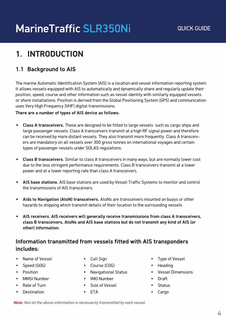
Information transmitted from vessels fitted with AIS transponders includes:
• Name of Vessel• Speed (SOG)• Position• MMSI Number• Rate of Turn• Destination
• Call Sign• Course (COG) • Navigational Status• IMO Number• Size of Vessel• ETA
• Type of Vessel• Heading• Vessel Dimensions• Draft• Status• Cargo
Note: Not all the above information is necessarily transmitted by each vessel.
MarineTraffic SLR350Ni QUICK GUIDE
5
1.2 The SLR350Ni
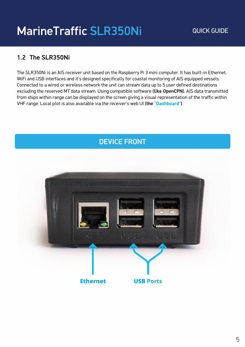
The SLR350Ni is an AIS receiver unit based on the Raspberry Pi 3 mini computer. It has built-in Ethernet, WiFi and USB interfaces and it’s designed specifically for coastal monitoring of AIS equipped vessels. Connected to a wired or wireless network the unit can stream data up to 5 user defined destinations excluding the reserved MT data stream. Using compatible software (like OpenCPN), AIS data transmitted from ships within range can be displayed on the screen giving a visual representation of the traffic within VHF range. Local plot is also available via the receiver’s web UI (the “Dashboard”).
DEVICE FRONT

MarineTraffic SLR350Ni QUICK GUIDE
6
DEVICE SIDE
Not all the available ports on the receiver are active / used at the moment. Please consult the installation diagram for more info.
MarineTraffic SLR350Ni QUICK GUIDE
7
2. INSTALLATION 2.1 Mounting
The SLR350Ni Receiver can only be used indoors and can be mounted to a suitable bulkhead or shelf.
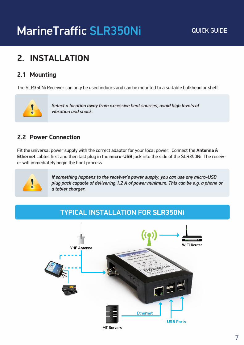
2.2 Power Connection
Fit the universal power supply with the correct adaptor for your local power. Connect the Antenna & Ethernet cables first and then last plug in the micro-USB jack into the side of the SLR350Ni. The receiv-er will immediately begin the boot process.
Select a location away from excessive heat sources, avoid high levels of vibration and shock.
If something happens to the receiver’s power supply, you can use any micro-USB plug pack capable of delivering 1.2 A of power minimum. This can be e.g. a phone or a tablet charger.
TYPICAL INSTALLATION FOR SLR350Ni

MarineTraffic SLR350Ni QUICK GUIDE
8
2.3 Antenna Installation
A VHF antenna is not included in this package. The minimum requirements for a suitable antenna are:
• Marine VHF band reception (for maximum performance, centred at 162MHz)• Gain of 3dB or more• Omni directional
Shore based reception is governed by local terrain, however an open view to the sea with an antenna mounted in the clear, at a height of approximately 20 metres will achieve a reception range of 25 nautical miles or more. A higher gain antenna can be used on shore to further increase the coverage. MarineTraffic suggests using the Sirio GP-3E base station omni antenna. The GP-3E must be “tuned” at 162MHz during assembly. This is done by adjusting the length of the main mast to approximately 112cm. The antenna connector type is PL-259 and the impedance is 50Ω.
3. CONFIGURATION The MarineTraffic SLR350Ni is commissioned upon first boot automatically. No configuration is necessary by the end user.
For the automatic configuration to work as intended, the SLR350Ni MUST be connected to the internet via Ethernet upon first boot! Allow for approximately 2 minutes for the boot & commissioning process to complete before attempting any change to the SLR350Ni settings.
• The higher the antenna is located, the greater the range.
• Mount the antenna with a relatively clear view of the horizon. Large obstructions that might shade the antenna should be avoided. Try to maintain a short RF cable run, preferably 10m or less for the RG-58 cable type or 20m for the RG-213 type.
• Normally an omni-directional antenna is recommended; however a direc-tional antenna such as a 3 element Yagi can be used to greatly increase performance in one particular direction.
• In order to protect the antenna installation from the elements and avoid water ingress, please apply waterproof sealant to both the RF connector and at the point where the sub-assemblies connect to the main body.
MarineTraffic SLR350Ni QUICK GUIDE
9
3.1 The MTUtility
You can assign a static IP, setup the WiFi connection and discover the connection details of your receiver using the MTUtility compatible with your computer’s operating system. The SLR350Ni expects a DHCP enabled network by default. The utility should be able to detect the unit even if static IPs are used on your network.You can download the program from the links below:
• Windows 64bit: www.marinetraffic.com/files/MTUtility/MTUtility-1.0-x64.msi
• Windows 32bit: www.marinetraffic.com/files/MTUtility/MTUtility-1.0-x86.msi
• Linux: www.marinetraffic.com/files/MTUtility/mtutility-1.0.deb
• OS X: www.marinetraffic.com/files/MTUtility/MTUtility.dmg
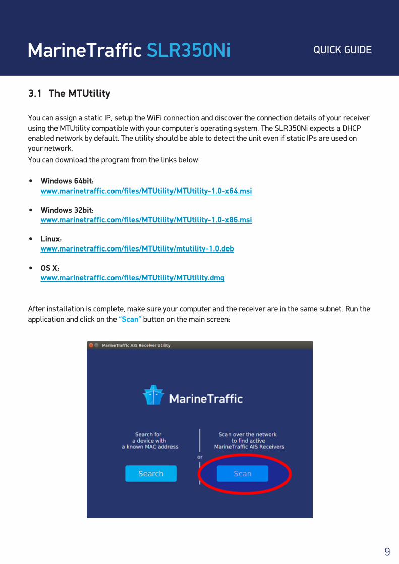
After installation is complete, make sure your computer and the receiver are in the same subnet. Run the application and click on the “Scan” button on the main screen:
MarineTraffic SLR350Ni QUICK GUIDE
10
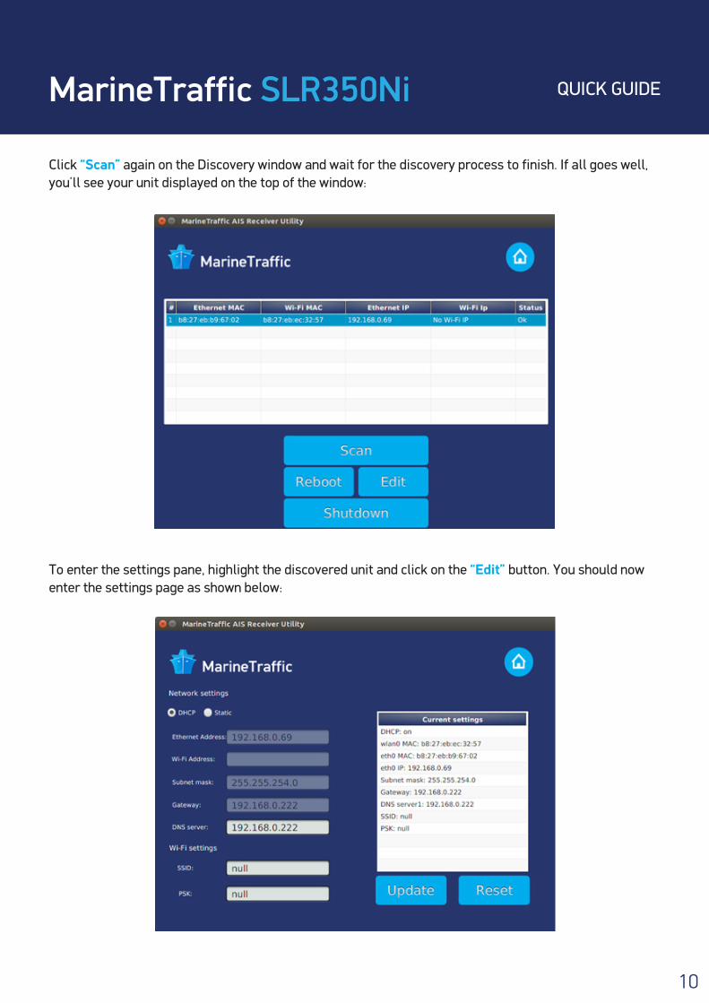
Click “Scan” again on the Discovery window and wait for the discovery process to finish. If all goes well, you’ll see your unit displayed on the top of the window:
To enter the settings pane, highlight the discovered unit and click on the “Edit” button. You should now enter the settings page as shown below:
MarineTraffic SLR350Ni QUICK GUIDE
11
Here you can assign a static IP to the SLR350Ni and also set up the WiFi connection. To do so enter the SSID of your wireless router on the “SSID” field and the password on the “PSK” field.
Note that the receiver is compatible only with WPA, WPA-PSK, WPA2 & WPS wireless protocols.
If you make an entry error, click on the “Reset” button to populate all fields with the current default values and start over.
When finished click on the “Update” button to write the changes to the device and reboot the receiver. Keep in mind that connectivity with the unit will be lost for a couple of minutes!
3.2 The Dashboard
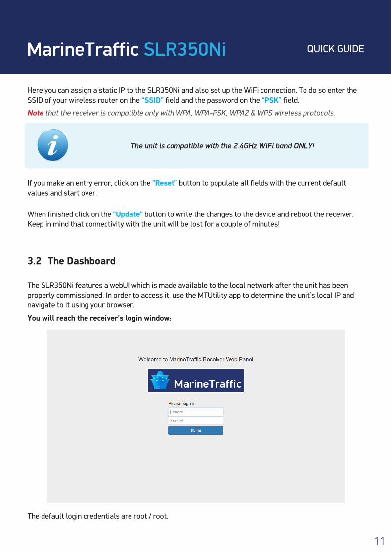
The SLR350Ni features a webUI which is made available to the local network after the unit has been properly commissioned. In order to access it, use the MTUtility app to determine the unit’s local IP and navigate to it using your browser.
You will reach the receiver’s login window:
The default login credentials are root / root.
The unit is compatible with the 2.4GHz WiFi band ONLY!
MarineTraffic SLR350Ni QUICK GUIDE
12
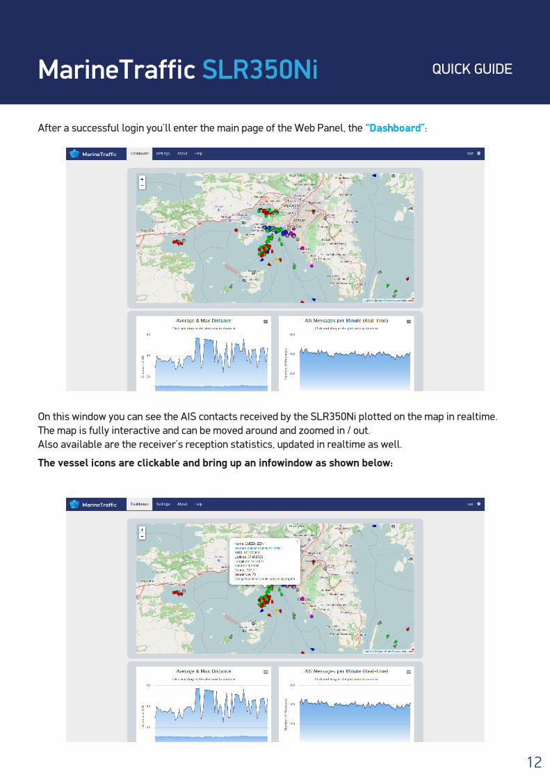
After a successful login you’ll enter the main page of the Web Panel, the “Dashboard”:
On this window you can see the AIS contacts received by the SLR350Ni plotted on the map in realtime. The map is fully interactive and can be moved around and zoomed in / out. Also available are the receiver’s reception statistics, updated in realtime as well.
The vessel icons are clickable and bring up an infowindow as shown below:
MarineTraffic SLR350Ni QUICK GUIDE
13
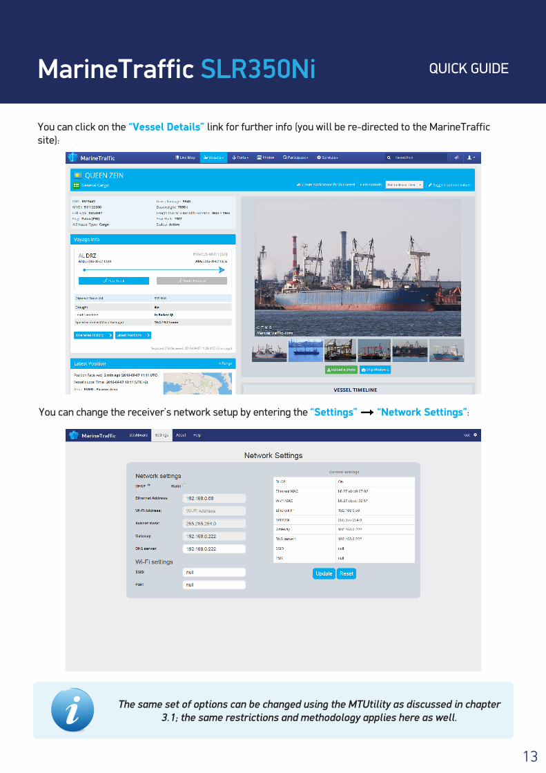
You can click on the “Vessel Details” link for further info (you will be re-directed to the MarineTraffic site):
You can change the receiver’s network setup by entering the “Settings” “Network Settings”:
The same set of options can be changed using the MTUtility as discussed in chapter 3.1; the same restrictions and methodology applies here as well.
MarineTraffic SLR350Ni QUICK GUIDE
14
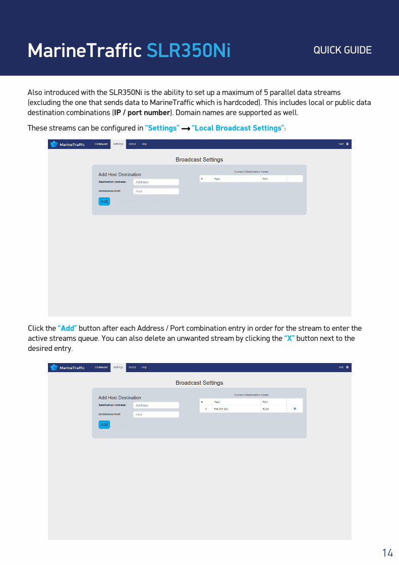
Also introduced with the SLR350Ni is the ability to set up a maximum of 5 parallel data streams (excluding the one that sends data to MarineTraffic which is hardcoded). This includes local or public data destination combinations (IP / port number). Domain names are supported as well.
These streams can be configured in “Settings” “Local Broadcast Settings”:
Click the “Add” button after each Address / Port combination entry in order for the stream to enter the active streams queue. You can also delete an unwanted stream by clicking the “X” button next to the desired entry.
MarineTraffic SLR350Ni QUICK GUIDE
15
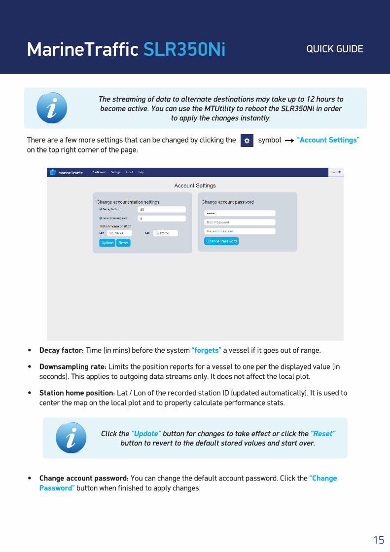
There are a few more settings that can be changed by clicking the symbol “Account Settings” on the top right corner of the page:
• Decay factor: Time (in mins) before the system “forgets” a vessel if it goes out of range.
• Downsampling rate: Limits the position reports for a vessel to one per the displayed value (in seconds). This applies to outgoing data streams only. It does not affect the local plot.
• Station home position: Lat / Lon of the recorded station ID (updated automatically). It is used to center the map on the local plot and to properly calculate performance stats.
• Change account password: You can change the default account password. Click the “Change Password” button when finished to apply changes.
The streaming of data to alternate destinations may take up to 12 hours to become active. You can use the MTUtility to reboot the SLR350Ni in order
to apply the changes instantly.
Click the “Update” button for changes to take effect or click the “Reset” button to revert to the default stored values and start over.
MarineTraffic SLR350Ni QUICK GUIDE
16
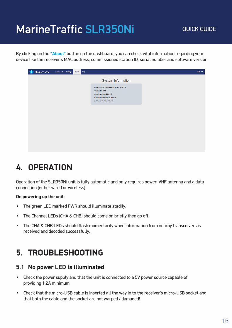
By clicking on the “About” button on the dashboard, you can check vital information regarding your device like the receiver’s MAC address, commissioned station ID, serial number and software version.
4. OPERATION Operation of the SLR350Ni unit is fully automatic and only requires power, VHF antenna and a data connection (either wired or wireless).
On powering up the unit:
• The green LED marked PWR should illuminate stadily.
• The Channel LEDs (CHA & CHB) should come on briefly then go off.
• The CHA & CHB LEDs should flash momentarily when information from nearby transceivers is received and decoded successfully.
5. TROUBLESHOOTING 5.1 No power LED is illuminated
• Check the power supply and that the unit is connected to a 5V power source capable of providing 1.2A minimum
• Check that the micro-USB cable is inserted all the way in to the receiver’s micro-USB socket and that both the cable and the socket are not warped / damaged!
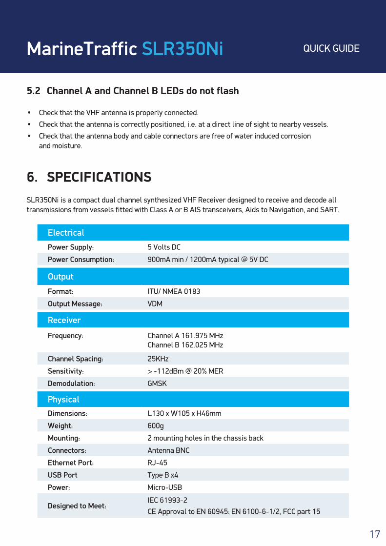
5.2 Channel A and Channel B LEDs do not flash
• Check that the VHF antenna is properly connected.
• Check that the antenna is correctly positioned, i.e. at a direct line of sight to nearby vessels.
• Check that the antenna body and cable connectors are free of water induced corrosion and moisture.
6. SPECIFICATIONS SLR350Ni is a compact dual channel synthesized VHF Receiver designed to receive and decode all transmissions from vessels fitted with Class A or B AIS transceivers, Aids to Navigation, and SART.
MarineTraffic SLR350Ni QUICK GUIDE
17
Electrical
Power Supply: 5 Volts DC
Power Consumption: 900mA min / 1200mA typical @ 5V DC
Physical
Dimensions: L130 x W105 x H46mm
Weight: 600g
Mounting: 2 mounting holes in the chassis back
Connectors: Antenna BNC
Ethernet Port: RJ-45
USB Port Type B x4
Power: Micro-USB
Designed to Meet:IEC 61993-2CE Approval to EN 60945: EN 6100-6-1/2, FCC part 15
Output
Format: ITU/ NMEA 0183
Output Message: VDM
Receiver
Frequency: Channel A 161.975 MHz Channel B 162.025 MHz
Channel Spacing: 25KHz
Sensitivity: > -112dBm @ 20% MER
Demodulation: GMSK
MarineTraffic SLR350Ni QUICK GUIDE
18
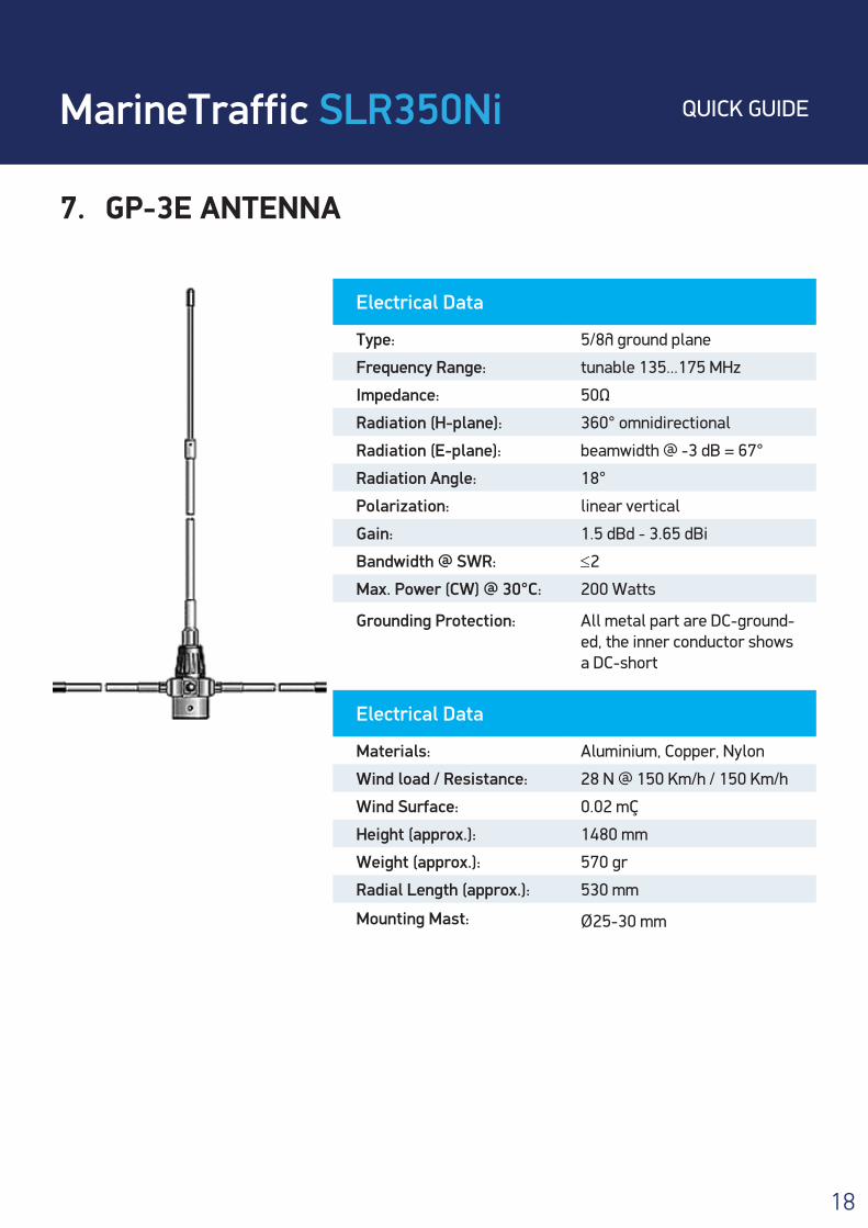
7. GP-3E ANTENNA
Electrical Data
Type: 5/8λ ground plane
Frequency Range: tunable 135...175 MHz
Impedance: 50Ω
Radiation (H-plane): 360° omnidirectional
Radiation (E-plane): beamwidth @ -3 dB = 67°
Radiation Angle: 18°
Polarization: linear vertical
Gain: 1.5 dBd - 3.65 dBi
Bandwidth @ SWR: ≤2
Max. Power (CW) @ 30°C: 200 Watts
Grounding Protection:
All metal part are DC-ground-ed, the inner conductor shows a DC-short
Electrical Data
Materials: Aluminium, Copper, Nylon
Wind load / Resistance: 28 N @ 150 Km/h / 150 Km/h
Wind Surface: 0.02 m²
Height (approx.): 1480 mm
Weight (approx.): 570 gr
Radial Length (approx.): 530 mm
Mounting Mast: Ø25-30 mm
MarineTraffic SLR350Ni QUICK GUIDE
19
8. LIMITED WARRANTY Comar Systems Ltd warrants this product to be free from defects in materials and manufacture for one year from the date of purchase. Comar Systems Ltd will, at its sole option, repair or replace any compo-nents that fail in normal use. Such repairs or replacement will be made at no charge to the customer for parts and labour. The customer is, however, responsible for any transportation costs incurred in return-ing the unit to Comar Systems Ltd.
This warranty does not cover failures due to abuse, misuse, accident or unauthorised alteration or repairs.
The above does not effect the statutory rights of the consumer.
Note: Every effort has been made to ensure that all information contained in this manual is accurate at the time of going to press. We therefore cannot take any responsibility for the content of this manual and advise that you take normal steps to ensure that the information is at its most current when you are reading this manual.
9. PRODUCT SUPPORT For questions regarding setting up and connecting to MarineTraffic please see the FAQ/Cover your area at:
https://help.marinetraffic.com/hc/en-us/articles/204725568-MarineTraffic-provid-ed-AIS-Receivers If you require further assistance please contact technical Support at:
For questions regarding the receiver and power supply please contact:
Comar Systems LimitedVittlefields Technology CentreForest RoadNewportIsle of Wight, PO30 4LYUnited Kingdom
Telephone: +44 (0) 1983 828900
E-mail: [email protected]
Internet: http://www.comarsystems.com