Embed Size (px)
Citation preview
Accredited to ISO 9001Qua l i t y AssuranceS T A N D A R D S
SmartGr upSmartGr upM A N U F A C T U R I N G
Quick Start Guide
0800 413 892
YOURSPEED
YOURSPEED
YOURSPEED
YOURSPEED
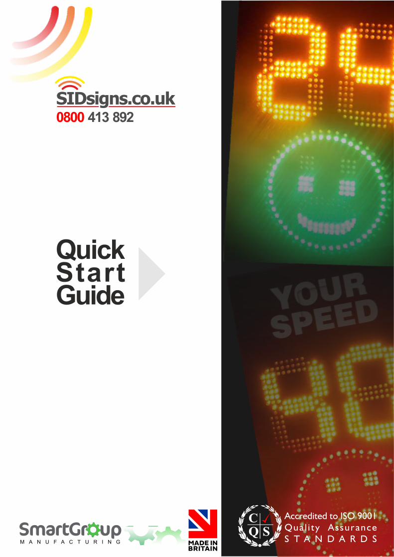
Startup process for dynamic speed indication models(inc. smiley face)
Sign will not react to approaching traffic properly if the startup processdoes not complete successfully as shown in this diagram.
Connect sign to 12v power source
Sign will return todormant state waitingfor traffic to approach
Centre segmentsboth flash Yellowand go out.
Pressing the RESET button on the underside of the sign will forcethe sign to restart/ reboot. When changing batteries if your signdoes not automatically startup press this button.
A few seconds laterSLOW DOWN flashes,the sign has completeda successful startup.
1 2 3 4
10-15 seconds
YOURSPEED
YOURSPEED
YOURSPEED
YOURSPEED
Test process for dynamic speed indication models (inc. smiley face)
This test process is a simple way of checking the correct functionalityof the led’s which make up any speed sign
Pressed once thetest button illuminatessection A.
Pressed again thetest button illuminatessection D + over speedmessage.
Pressed again the testbutton illuminatessection B + over speedmessage.
Pressing the TEST button illuminates the sign sequentially with allsegments lighting one at a time while over & under speed messagesilluminate in alternate. Test direction is clockwise
Pressed again the testbutton illuminatessection C.
1 2 3 4
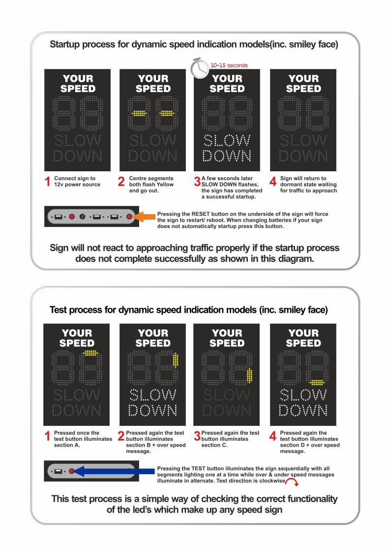
A basic testing process which shows whether your sign has power& is operational.
Test process for fixed message formats.
Connect sign to 12v power source
After test button isreleased sign will returnto dormant state.
Pressing the TEST button on the underside of the sign instructs thesystem to illuminate all led’s. This basic process gives a visual reference that the sign is powered & working.
Press the test button,all led’s will light.1 2 3
Sign will not react to approaching traffic properly if the startup processdoes not complete successfully as shown in this diagram.
Startup process for fixed message formats.
Connect sign to 12v power source
Sign will return todormant state waitingfor traffic to approach
Pressing the RESET button on the underside of the sign will forcethe sign to restart/ reboot. When changing batteries if your signdoes not automatically startup press this button.
A few seconds laterthe sign will flashbriefly. The sign hascompleted a successfulstartup routine
1 2 3
10-15 seconds
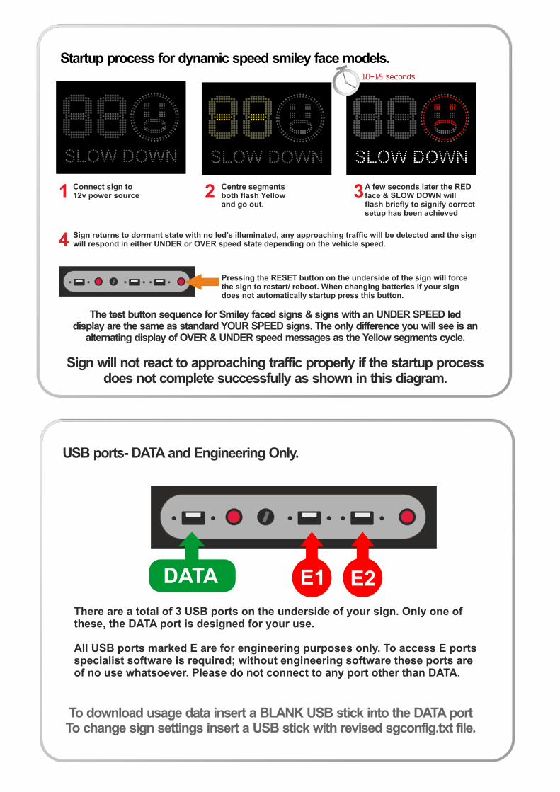
Startup process for dynamic speed smiley face models.10-15 seconds
Sign will not react to approaching traffic properly if the startup processdoes not complete successfully as shown in this diagram.
The test button sequence for Smiley faced signs & signs with an UNDER SPEED leddisplay are the same as standard YOUR SPEED signs. The only difference you will see is an
alternating display of OVER & UNDER speed messages as the Yellow segments cycle.
Connect sign to 12v power source
Sign returns to dormant state with no led’s illuminated, any approaching traffic will be detected and the signwill respond in either UNDER or OVER speed state depending on the vehicle speed.
Centre segmentsboth flash Yellowand go out.
Pressing the RESET button on the underside of the sign will forcethe sign to restart/ reboot. When changing batteries if your signdoes not automatically startup press this button.
A few seconds later the REDface & SLOW DOWN will flash briefly to signify correctsetup has been achieved
1
4
2 3
USB ports- DATA and Engineering Only.
To download usage data insert a BLANK USB stick into the DATA portTo change sign settings insert a USB stick with revised sgconfig.txt file.
There are a total of 3 USB ports on the underside of your sign. Only one ofthese, the DATA port is designed for your use.
All USB ports marked E are for engineering purposes only. To access E portsspecialist software is required; without engineering software these ports areof no use whatsoever. Please do not connect to any port other than DATA.
E1 E2DATA
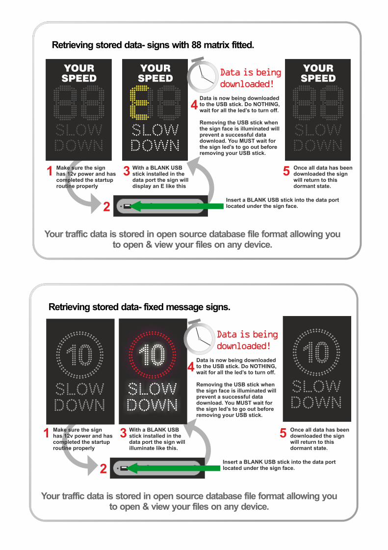
Retrieving stored data- fixed message signs.
Your traffic data is stored in open source database file format allowing youto open & view your files on any device.
Make sure the signhas 12v power and hascompleted the startup routine properly
Once all data has beendownloaded the signwill return to thisdormant state.
Data is now being downloadedto the USB stick. Do NOTHING,wait for all the led’s to turn off.
Removing the USB stick when the sign face is illuminated willprevent a successful datadownload. You MUST wait forthe sign led’s to go out beforeremoving your USB stick.
With a BLANK USBstick installed in thedata port the sign willilluminate like this.
Insert a BLANK USB stick into the data portlocated under the sign face.
1
2
3 5
4
Data is beingdownloaded!
YOURSPEED
YOURSPEED
YOURSPEED
Retrieving stored data- signs with 88 matrix fitted.
Your traffic data is stored in open source database file format allowing youto open & view your files on any device.
Make sure the signhas 12v power and hascompleted the startup routine properly
Once all data has beendownloaded the signwill return to thisdormant state.
Data is now being downloadedto the USB stick. Do NOTHING,wait for all the led’s to turn off.
Removing the USB stick when the sign face is illuminated willprevent a successful datadownload. You MUST wait forthe sign led’s to go out beforeremoving your USB stick.
With a BLANK USBstick installed in thedata port the sign willdisplay an E like this
Insert a BLANK USB stick into the data portlocated under the sign face.
1
2
3 5
4
Data is beingdownloaded!
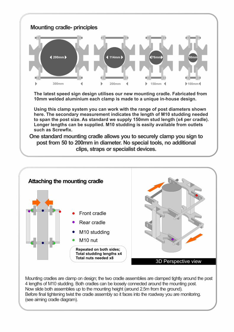
Attaching the mounting cradle
Mounting cradles are clamp on design; the two cradle assemblies are clamped tightly around the post4 lengths of M10 studding. Both cradles can be loosely connected around the mounting post. Now slide both assemblies up to the mounting height (around 2.5m from the ground). Before final tightening twist the cradle assembly so it faces into the roadway you are monitoring.(see aiming cradle diagram).
3D Perspective view
M10 studding
Front cradle
Rear cradle
M10 nut
Repeated on both sides;Total studding lengths x4Total nuts needed x8
Mounting cradle- principles
One standard mounting cradle allows you to securely clamp you sign topost from 50 to 200mm in diameter. No special tools, no additional
clips, straps or specialist devices.
The latest speed sign design utilises our new mounting cradle. Fabricated from10mm welded aluminium each clamp is made to a unique in-house design.
Using this clamp system you can work with the range of post diameters shownhere. The secondary measurement indicates the length of M10 studding neededto span the post size. As standard we supply 150mm stud length (x4 per cradle).Longer lengths can be supplied. M10 studding is easily available from outletssuch as Screwfix.
114mm200mm
300mm 200mm 150mm
76mm
100mm
50mm
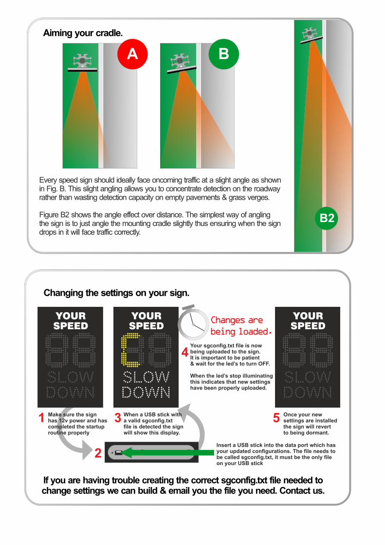
Every speed sign should ideally face oncoming traffic at a slight angle as shown in Fig. B. This slight angling allows you to concentrate detection on the roadwayrather than wasting detection capacity on empty pavements & grass verges.
Figure B2 shows the angle effect over distance. The simplest way of anglingthe sign is to just angle the mounting cradle slightly thus ensuring when the signdrops in it will face traffic correctly.
Aiming your cradle.
B2
A B
YOURSPEED
YOURSPEED
YOURSPEED
Changing the settings on your sign.
If you are having trouble creating the correct sgconfig.txt file needed tochange settings we can build & email you the file you need. Contact us.
Make sure the signhas 12v power and hascompleted the startup routine properly
Once your newsettings are installedthe sign will revertto being dormant.
Your sgconfig.txt file is nowbeing uploaded to the sign.It is important to be patient& wait for the led’s to turn OFF.
When the led’s stop illuminatingthis indicates that new settingshave been properly uploaded.
When a USB stick witha valid sgconfig.txt file is detected the signwill show this display.
Insert a USB stick into the data port which hasyour updated configurations. The file needs to be called sgconfig.txt, it must be the only file on your USB stick
1
2
3 5
4
Changes arebeing loaded.
#define DEFAULT_SIGN_ACTIVE_MIN_SPEED 15 #define DEFAULT_SIGN_ACTIVE_MAX_SPEED 70
#define NUMERIC_DIGITS_ON_SPEED 15 #define NUMERIC_DIGITS_OFF_SPEED 60
#define DEFAULT_GOOD_OUTPUT_ON_SPEED 15 #define DEFAULT_GOOD_OUTPUT_OFF_SPEED 30 #define DEFAULT_GOOD_OUTPUT_FLASHES 0
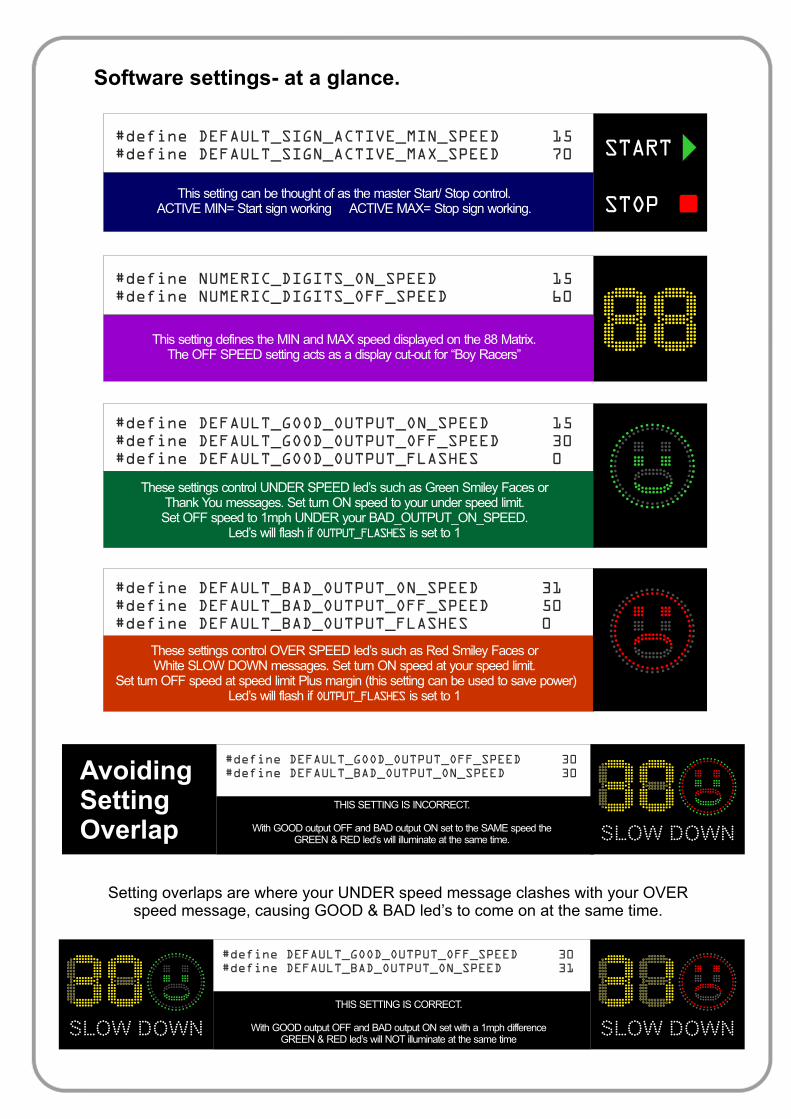
This setting can be thought of as the master Start/ Stop control.ACTIVE MIN= Start sign working ACTIVE MAX= Stop sign working.
This setting defines the MIN and MAX speed displayed on the 88 Matrix.The OFF SPEED setting acts as a display cut-out for “Boy Racers”
These settings control UNDER SPEED led’s such as Green Smiley Faces orThank You messages. Set turn ON speed to your under speed limit. Set OFF speed to 1mph UNDER your BAD_OUTPUT_ON_SPEED.
Led’s will flash if OUTPUT_FLASHES is set to 1
#define DEFAULT_BAD_OUTPUT_ON_SPEED 31 #define DEFAULT_BAD_OUTPUT_OFF_SPEED 50 #define DEFAULT_BAD_OUTPUT_FLASHES 0
These settings control OVER SPEED led’s such as Red Smiley Faces orWhite SLOW DOWN messages. Set turn ON speed at your speed limit.
Set turn OFF speed at speed limit Plus margin (this setting can be used to save power)Led’s will flash if OUTPUT_FLASHES is set to 1
START
STOP
#define DEFAULT_GOOD_OUTPUT_OFF_SPEED 30 #define DEFAULT_BAD_OUTPUT_ON_SPEED 30
#define DEFAULT_GOOD_OUTPUT_OFF_SPEED 30 #define DEFAULT_BAD_OUTPUT_ON_SPEED 31
THIS SETTING IS INCORRECT.
With GOOD output OFF and BAD output ON set to the SAME speed theGREEN & RED led’s will illuminate at the same time.
THIS SETTING IS CORRECT.
With GOOD output OFF and BAD output ON set with a 1mph differenceGREEN & RED led’s will NOT illuminate at the same time
AvoidingSetting Overlap
Setting overlaps are where your UNDER speed message clashes with your OVER speed message, causing GOOD & BAD led’s to come on at the same time.
Software settings- at a glance.
#define DEFAULT_SIGN_ACTIVE_MIN_SPEED 15 #define DEFAULT_SIGN_ACTIVE_MAX_SPEED 70
#define NUMERIC_DIGITS_ON_SPEED 15 #define NUMERIC_DIGITS_OFF_SPEED 60
#define DEFAULT_GOOD_OUTPUT_ON_SPEED 15 #define DEFAULT_GOOD_OUTPUT_OFF_SPEED 30 #define DEFAULT_GOOD_OUTPUT_FLASHES 0
#define DEFAULT_BAD_OUTPUT_ON_SPEED 31 #define DEFAULT_BAD_OUTPUT_OFF_SPEED 50 #define DEFAULT_BAD_OUTPUT_FLASHES 1
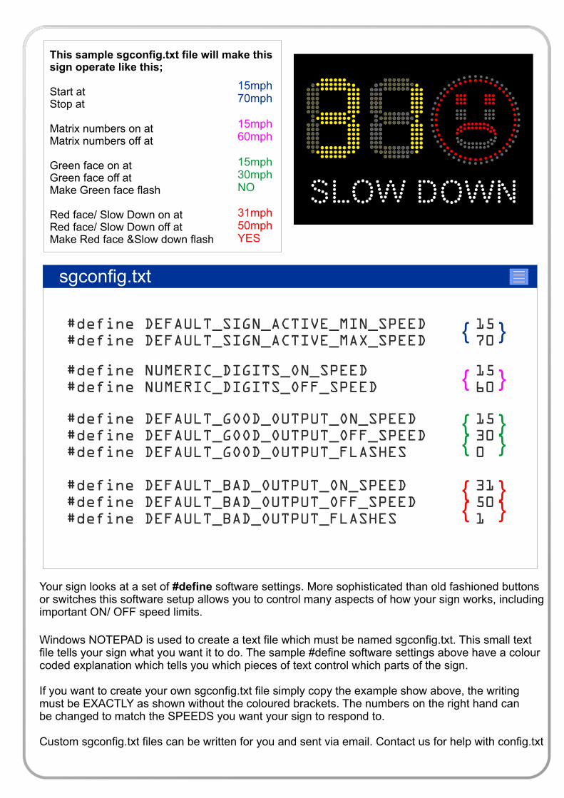
sgconfig.txt
Your sign looks at a set of #define software settings. More sophisticated than old fashioned buttonsor switches this software setup allows you to control many aspects of how your sign works, includingimportant ON/ OFF speed limits.
Windows NOTEPAD is used to create a text file which must be named sgconfig.txt. This small textfile tells your sign what you want it to do. The sample #define software settings above have a colourcoded explanation which tells you which pieces of text control which parts of the sign.
If you want to create your own sgconfig.txt file simply copy the example show above, the writing must be EXACTLY as shown without the coloured brackets. The numbers on the right hand canbe changed to match the SPEEDS you want your sign to respond to.
Custom sgconfig.txt files can be written for you and sent via email. Contact us for help with config.txt
This sample sgconfig.txt file will make thissign operate like this;
Start atStop at
Matrix numbers on atMatrix numbers off at
Green face on atGreen face off atMake Green face flash
Red face/ Slow Down on atRed face/ Slow Down off atMake Red face &Slow down flash
15mph70mph
15mph60mph
15mph30mphNO
31mph50mphYES
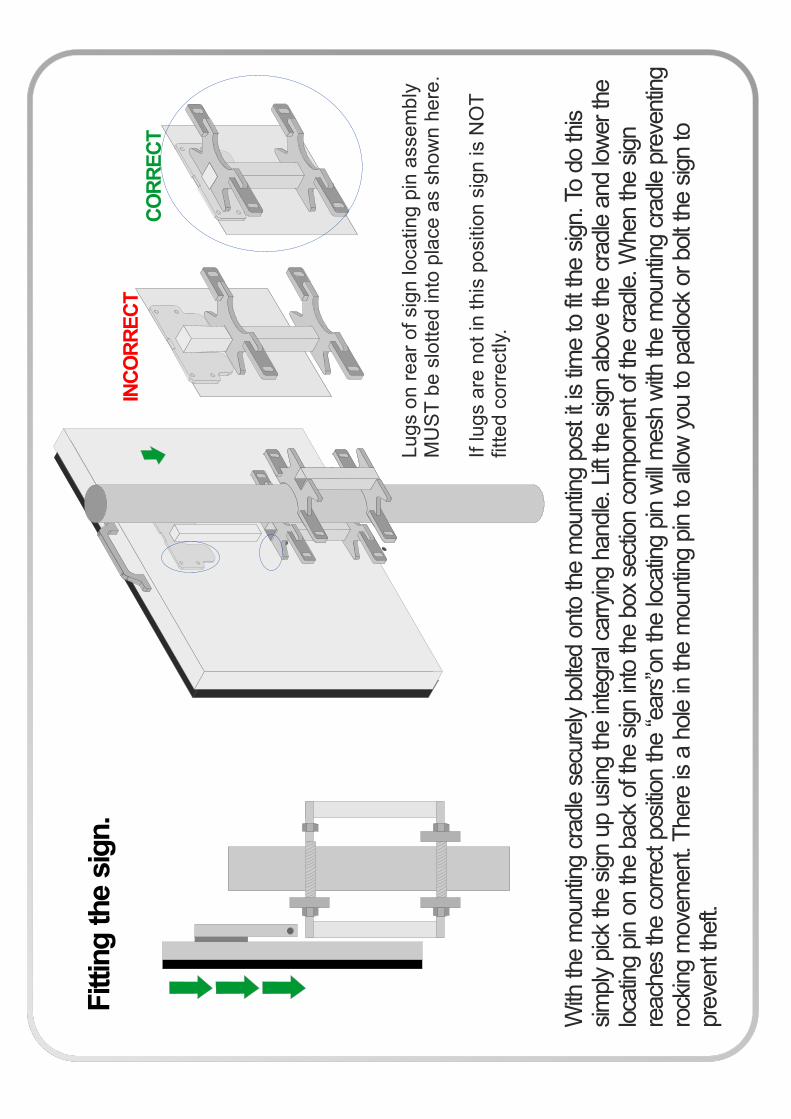
Fitt
ing
the s
ign.
With
the
mou
ntin
g c
radl
e s
ecur
ely b
olte
d o
nto
the
mou
ntin
g p
ost i
t is
time
to fi
t the
sig
n. T
o d
o th
is
sim
ply p
ick
the
sig
n u
p u
sing
the
inte
gral
car
ryin
g h
andl
e. L
ift th
e s
ign
abo
ve th
e c
radl
e a
nd lo
wer
the
loca
ting
pin
on
the
bac
k of
the
sig
n in
to th
e b
ox s
ectio
n c
ompo
nent
of t
he c
radl
e. W
hen
the
sig
nre
ache
s th
e c
orre
ct p
osition
the
“ear
s”on
the
loca
ting
pin
will m
esh
with
the
mou
ntin
g c
radl
e p
reve
ntin
gro
ckin
g m
ovem
ent.
The
re is
a h
ole
in th
e m
ount
ing
pin
to a
llow
you
to p
adlo
ck o
r bo
lt th
e s
ign
topr
even
t the
ft.
Lugs
on r
ear
of si
gn lo
catin
g p
in a
ssem
bly
MU
ST
be s
lotted in
to p
lace
as
show
n h
ere
.
If lu
gs
are
not in
this
posi
tion s
ign is
NO
Tfit
ted c
orr
ect
ly.
INC
OR
RE
CT
CO
RR
EC
T
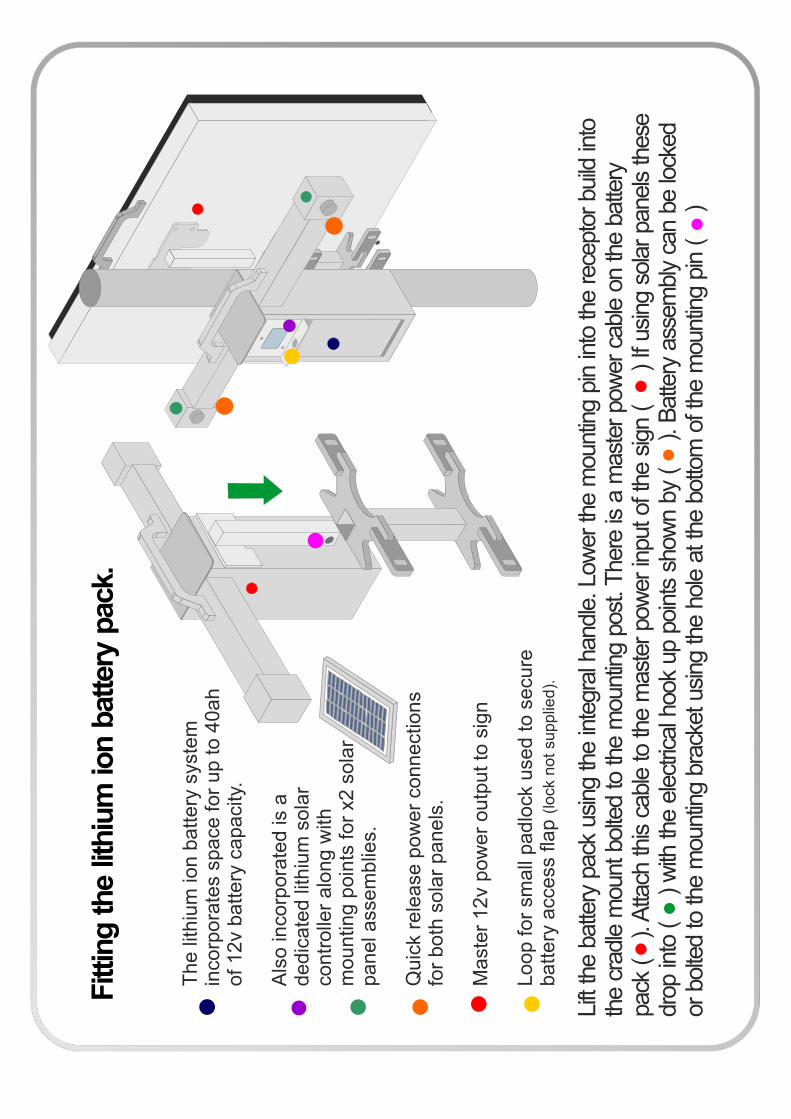
Fitt
ing
the
lith
ium
ion
bat
tery
pac
k.
Lift
the b
atte
ry p
ack
usin
g th
e in
tegr
al h
andl
e. L
ower
the m
ount
ing p
in in
to th
e re
cept
or b
uild
into
the c
radl
e m
ount
bol
ted to
the m
ount
ing p
ost.
The
re is
a m
aste
r po
wer
cab
le o
n th
e b
atte
rypa
ck ( ).
Atta
ch th
is c
able
to th
e m
aste
r po
wer
inpu
t of t
he s
ign ( ) If
usi
ng s
olar
pan
els
thes
e
drop
into
( )
with
the e
lect
rical
hoo
k up
poi
nts
show
n b
y (
).
Bat
tery
ass
embl
y ca
n b
e lo
cked
or b
olte
d to
the m
ount
ing b
rack
et u
sing
the h
ole a
t the
bot
tom
of t
he m
ount
ing p
in ( )
Th
e li
thiu
m io
n b
att
ery
syst
em
in
corp
ora
tes
sp
ace
fo
r u
p t
o 4
0a
ho
f 1
2v b
att
ery
ca
pa
city
.
Als
o in
co
rpo
rate
d is
ad
ed
ica
ted
lith
ium
so
lar
con
tro
ller
alo
ng
with
mo
un
ting
po
ints
fo
r x2
so
lar
pa
ne
l a
sse
mb
lies.
Qu
ick
rele
ase
po
we
r co
nn
ect
ion
sfo
r b
oth
so
lar
pa
ne
ls.
Ma
ste
r 1
2v
po
we
r o
utp
ut to
sig
n
Lo
op
fo
r sm
all
pa
dlo
ck u
se
d t
o s
ecu
reb
att
ery
acc
ess
fla
p (
lock
no
t su
pp
lied
).
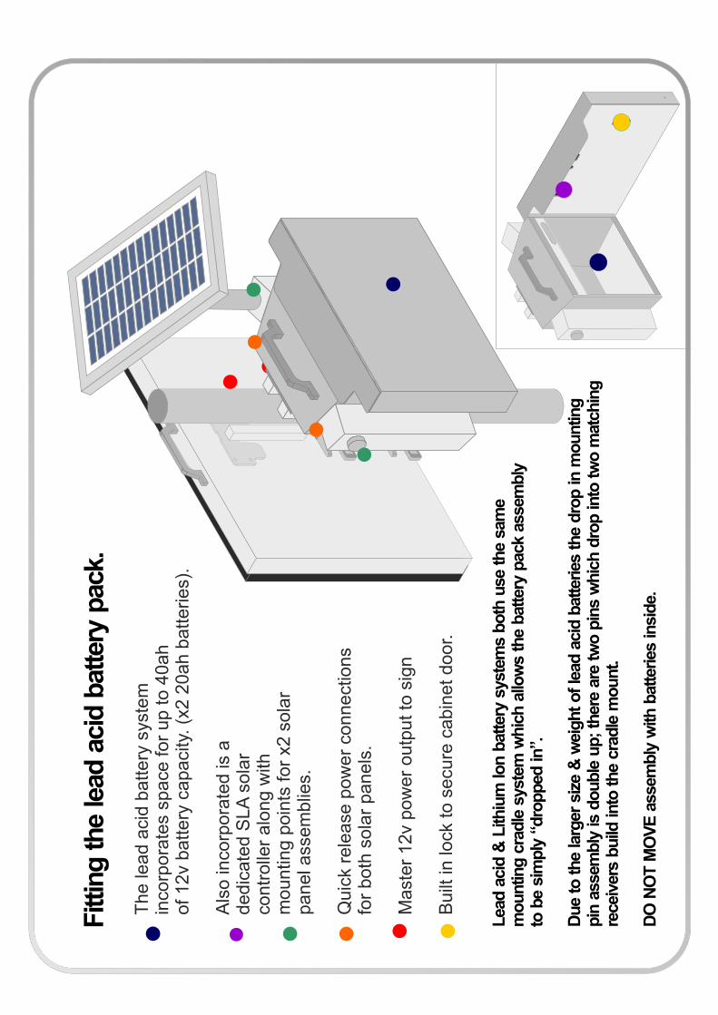
Fitt
ing
the
lead
aci
d b
atte
ry p
ack.
Lea
d a
cid
& L
ithiu
m Io
n b
atte
ry s
yste
ms b
oth
use
the s
ame
mountin
g c
radle
sys
tem
whic
h a
llow
s th
e b
atte
ry p
ack a
ssem
bly
to b
e s
imply
“dro
pped
in”.
Due to
the la
rger
siz
e &
wei
ght of le
ad a
cid
bat
teries
the d
rop
in m
ountin
gpin
ass
embly
is d
ouble
up; th
ere a
re tw
o p
ins w
hic
h d
rop
into
two
mat
chin
gre
ceiv
ers b
uild
into
the c
radle
mount.
DO
NO
T M
OV
E a
ssem
bly
with
bat
teries
insi
de.
Th
e le
ad
aci
d b
att
ery
sys
tem
in
corp
ora
tes
spa
ce f
or
up
to
40
ah
of
12
v b
att
ery
ca
pa
city
. (x
2 2
0a
h b
atte
rie
s).
Als
o in
corp
ora
ted
is
ad
ed
ica
ted
SL
A s
ola
rco
ntr
olle
r a
lon
g w
ithm
ou
ntin
g p
oin
ts f
or
x2 s
ola
rp
an
el a
sse
mb
lies.
Qu
ick
rele
ase
po
we
r co
nn
ect
ion
sfo
r b
oth
so
lar
pa
ne
ls.
Ma
ste
r 1
2v
po
we
r o
utp
ut
to s
ign
Bu
ilt in
lock
to
se
cu
re c
ab
ine
t d
oo
r.
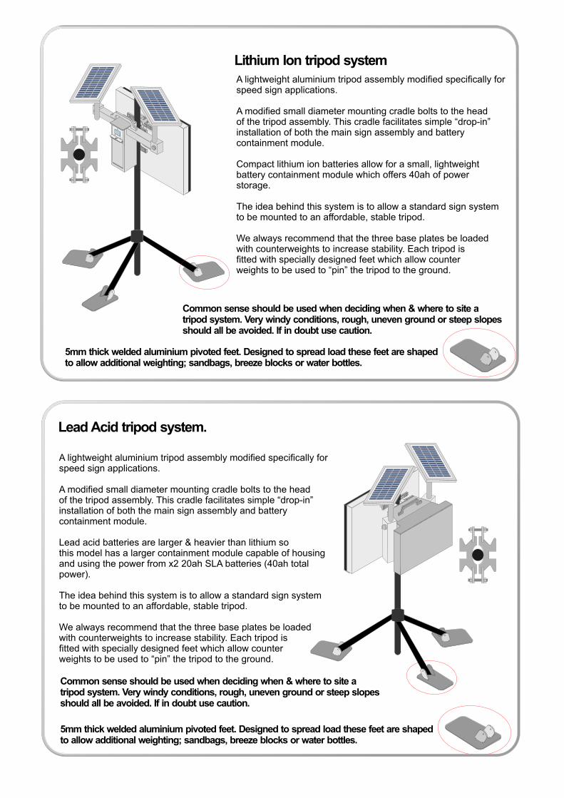
Lead Acid tripod system.
5mm thick welded aluminium pivoted feet. Designed to spread load these feet are shapedto allow additional weighting; sandbags, breeze blocks or water bottles.
5mm thick welded aluminium pivoted feet. Designed to spread load these feet are shapedto allow additional weighting; sandbags, breeze blocks or water bottles.
Common sense should be used when deciding when & where to site a tripod system. Very windy conditions, rough, uneven ground or steep slopesshould all be avoided. If in doubt use caution.
Common sense should be used when deciding when & where to site a tripod system. Very windy conditions, rough, uneven ground or steep slopesshould all be avoided. If in doubt use caution.
Lithium Ion tripod system
A lightweight aluminium tripod assembly modified specifically forspeed sign applications.
A modified small diameter mounting cradle bolts to the headof the tripod assembly. This cradle facilitates simple “drop-in”installation of both the main sign assembly and batterycontainment module.
Lead acid batteries are larger & heavier than lithium sothis model has a larger containment module capable of housingand using the power from x2 20ah SLA batteries (40ah totalpower).
The idea behind this system is to allow a standard sign systemto be mounted to an affordable, stable tripod.
We always recommend that the three base plates be loadedwith counterweights to increase stability. Each tripod isfitted with specially designed feet which allow counterweights to be used to “pin” the tripod to the ground.
A lightweight aluminium tripod assembly modified specifically forspeed sign applications.
A modified small diameter mounting cradle bolts to the headof the tripod assembly. This cradle facilitates simple “drop-in”installation of both the main sign assembly and batterycontainment module.
Compact lithium ion batteries allow for a small, lightweightbattery containment module which offers 40ah of powerstorage.
The idea behind this system is to allow a standard sign systemto be mounted to an affordable, stable tripod.
We always recommend that the three base plates be loadedwith counterweights to increase stability. Each tripod isfitted with specially designed feet which allow counterweights to be used to “pin” the tripod to the ground.
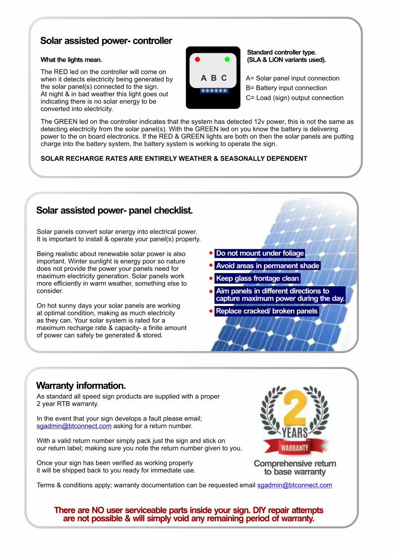
Solar assisted power- controller
Solar assisted power- panel checklist.
Standard controller type. (SLA & LiON variants used).What the lights mean.
The RED led on the controller will come on when it detects electricity being generated by the solar panel(s) connected to the sign.At night & in bad weather this light goes out indicating there is no solar energy to be converted into electricity.
Solar panels convert solar energy into electrical power.It is important to install & operate your panel(s) properly.
Being realistic about renewable solar power is alsoimportant. Winter sunlight is energy poor so naturedoes not provide the power your panels need formaximum electricity generation. Solar panels workmore efficiently in warm weather, something else toconsider.
On hot sunny days your solar panels are workingat optimal condition, making as much electricityas they can. Your solar system is rated for amaximum recharge rate & capacity- a finite amountof power can safely be generated & stored.
The GREEN led on the controller indicates that the system has detected 12v power, this is not the same asdetecting electricity from the solar panel(s). With the GREEN led on you know the battery is deliveringpower to the on board electronics. If the RED & GREEN lights are both on then the solar panels are puttingcharge into the battery system, the battery system is working to operate the sign.
SOLAR RECHARGE RATES ARE ENTIRELY WEATHER & SEASONALLY DEPENDENT
A= Solar panel input connection
B= Battery input connection
C= Load (sign) output connection
A B C
Do not mount under foliage
Avoid areas in permanent shade
Keep glass frontage clean
Aim panels in different directions tocapture maximum power during the day.
Replace cracked/ broken panels
Warranty information.
Comprehensive return to base warranty
There are NO user serviceable parts inside your sign. DIY repair attemptsare not possible & will simply void any remaining period of warranty.
As standard all speed sign products are supplied with a proper2 year RTB warranty.
In the event that your sign develops a fault please email; asking for a return [email protected]
With a valid return number simply pack just the sign and stick onour return label; making sure you note the return number given to you.
Once your sign has been verified as working properly it will be shipped back to you ready for immediate use.
Terms & conditions apply; warranty documentation can be requested email [email protected]
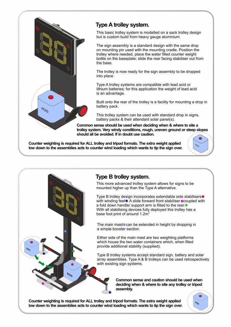
Counter weighting is required for ALL trolley and tripod formats. The extra weight appliedlow down to the assemblies acts to counter wind loading which wants to tip the sign over.
Counter weighting is required for ALL trolley and tripod formats. The extra weight appliedlow down to the assemblies acts to counter wind loading which wants to tip the sign over.
Common sense should be used when deciding when & where to site a trolley system. Very windy conditions, rough, uneven ground or steep slopesshould all be avoided. If in doubt use caution.
Common sense and caution should be used whendeciding when & where to site any trolley or tripodassembly.
Type A trolley system.
Type B trolley system.
This basic trolley system is modelled on a sack trolley design but is custom build from heavy gauge aluminium.
The sign assembly is a standard design with the same drop on mounting pin used with the mounting cradle. Position thetrolley where needed, place the water filled counter weightbottle on the baseplate; slide the rear facing stabiliser out fromthe base.
The trolley is now ready for the sign assembly to be droppedinto place.
Type A trolley systems are compatible with lead acid orlithium batteries; for this application the weight of lead acidis an advantage.
Built onto the rear of the trolley is a facility for mounting a drop inbattery pack.
This trolley system can be used with standard drop in signs,battery packs & their attendant solar panel(s).
The main mast can be extended in height by dropping ina simple booster section.
Either side of the main mast are two weighting platformswhich house the two water containers which, when filledprovide additional stability (supplied).
Type B trolley systems accept standard sign, battery and solararray assemblies. Type A & B trolleys can be used retrospectivelywith existing sign systems.
This more advanced trolley system allows for signs to bemounted higher up than the Type A alternative.
Type B trolley design incorporates extendable side stabiliserswith winding feet . A slide forward front stabiliser coupled with a fold down handle/ support arm is fitted to the rear.With all stabilising devices fully deployed this trolley has a
2base foot print of around 1.2m
LiONL I T H I U M I O N
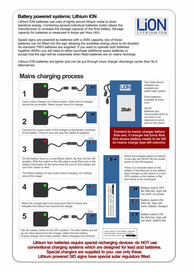
Battery powered systems; Lithium ION
Lithium Ion batteries require special recharging devices- do NOT use conventional charging systems which are designed for lead acid batteries.
Special chargers are supplied to you- use only these.Lithium powered SID signs have special solar regulators fitted.
Lithium ION batteries use coils of tightly wound lithium metal to store electrical energy. Combining several individual batteries (cells) allows themanufacturer to increase the storage capacity of the final battery. Storagecapacity for batteries is measured in Amps per Hour (Ah).
Speed signs are powered by batteries with a 20Ah capacity, two of thesebatteries can be fitted into the sign allowing the available energy store to be doubled. As standard TWO batteries are supplied. If you want to operate both batteries together (40Ah) you will need to either purchase additional spare batteries oraccept that the sign will be inoperable when fitted batteries are on mains recharge.
Lithium ION batteries are lighter and can be put through more charge/ discharge cycles than SLAalternatives.
0 I
0 I
0 I
0 I
0 I
0 I
0 I
0 I
0 I
Insert mains charger into mains socket; Green led on charger should be illuminated. Mains power found for charger.
Flip the battery switch to the OFF position. The Red battery led will go out. Now disconnect the charger cable from the battery.Unplug charger from mains socket. Mains charging now finished.
Connect the output cable of the charger to the female connector of the battery. There is only one way the cables fit together.
On the battery there is a small Black switch; flip this into the ONposition. With the switch in the ON state a small Red Led on thebattery illuminates. At the same time the Led on the charger willturn from Green to Red.
The lithium battery is now under mains charging. Do nothingelse at this stage.
When the charged battery is placed in the sign you MUST flip the power switch to the ON position.
There is a reminder label on thebattery. If the Red led on the battery does not light up the switch is in the OFF position or the battery is flat and needs to be recharged.
Two 20ah lithiumbatteries aresupplied perspeed sign system.
Extra batteries available at extracost.
NOTE.Batteries areconsumable items &will need to bereplaced at somepoint in the future.
When the charger light turns back from Red to Green this indicates the battery has reached full charge.
1
2
3
4
5
Mains charging process
Battery switch OFF.No Red led. Sign willnot work, no power.
Battery switch ON.No Red led. Sign willnot work, battery flat.
Battery switch ON.Red led. Sign willwork, battery charged.
LiONL I T H I U M I O N
20ah
Connect to mains charger before first use; if charger led turns Red
this shows battery needs to be lefton mains charge (see left column).
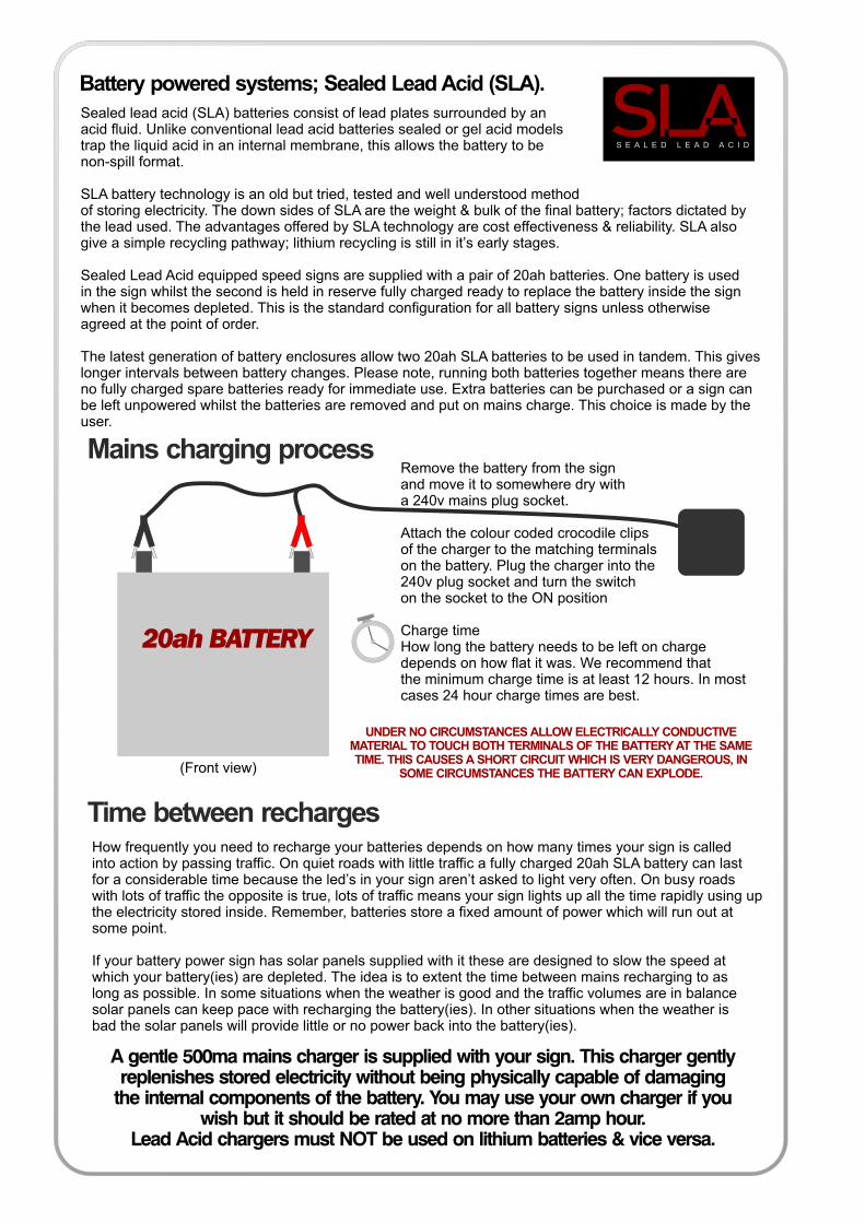
SLAS E A L E D L E A D A C I D
Battery powered systems; Sealed Lead Acid (SLA).
A gentle 500ma mains charger is supplied with your sign. This charger gentlyreplenishes stored electricity without being physically capable of damaging
the internal components of the battery. You may use your own charger if youwish but it should be rated at no more than 2amp hour.
Lead Acid chargers must NOT be used on lithium batteries & vice versa.
Sealed lead acid (SLA) batteries consist of lead plates surrounded by anacid fluid. Unlike conventional lead acid batteries sealed or gel acid modelstrap the liquid acid in an internal membrane, this allows the battery to benon-spill format.
SLA battery technology is an old but tried, tested and well understood methodof storing electricity. The down sides of SLA are the weight & bulk of the final battery; factors dictated bythe lead used. The advantages offered by SLA technology are cost effectiveness & reliability. SLA alsogive a simple recycling pathway; lithium recycling is still in it’s early stages.
Sealed Lead Acid equipped speed signs are supplied with a pair of 20ah batteries. One battery is usedin the sign whilst the second is held in reserve fully charged ready to replace the battery inside the signwhen it becomes depleted. This is the standard configuration for all battery signs unless otherwise agreed at the point of order.
The latest generation of battery enclosures allow two 20ah SLA batteries to be used in tandem. This giveslonger intervals between battery changes. Please note, running both batteries together means there areno fully charged spare batteries ready for immediate use. Extra batteries can be purchased or a sign canbe left unpowered whilst the batteries are removed and put on mains charge. This choice is made by theuser.
How frequently you need to recharge your batteries depends on how many times your sign is calledinto action by passing traffic. On quiet roads with little traffic a fully charged 20ah SLA battery can lastfor a considerable time because the led’s in your sign aren’t asked to light very often. On busy roadswith lots of traffic the opposite is true, lots of traffic means your sign lights up all the time rapidly using upthe electricity stored inside. Remember, batteries store a fixed amount of power which will run out atsome point.
If your battery power sign has solar panels supplied with it these are designed to slow the speed atwhich your battery(ies) are depleted. The idea is to extent the time between mains recharging to aslong as possible. In some situations when the weather is good and the traffic volumes are in balancesolar panels can keep pace with recharging the battery(ies). In other situations when the weather is bad the solar panels will provide little or no power back into the battery(ies).
Mains charging process
Time between recharges
UNDER NO CIRCUMSTANCES ALLOW ELECTRICALLY CONDUCTIVE MATERIAL TO TOUCH BOTH TERMINALS OF THE BATTERY AT THE SAMETIME. THIS CAUSES A SHORT CIRCUIT WHICH IS VERY DANGEROUS, IN
SOME CIRCUMSTANCES THE BATTERY CAN EXPLODE.(Front view)
Remove the battery from the sign and move it to somewhere dry with a 240v mains plug socket.
Attach the colour coded crocodile clipsof the charger to the matching terminalson the battery. Plug the charger into the240v plug socket and turn the switchon the socket to the ON position
Charge timeHow long the battery needs to be left on chargedepends on how flat it was. We recommend that the minimum charge time is at least 12 hours. In mostcases 24 hour charge times are best.
20ah BATTERY
Advice to users....
Ask before returning....
Never attempt DIY repair....
Check this manual first.....
Consider your location.....
In most cases the prime cause of a sign “not working” is simply a lack of power. Every battery powered signis shipped with brand new batteries which the user is asked to monitor, maintain and mains rechargeas and when required. If a proper battery maintenance regime is not in place your sign will run out ofpower at random intervals. This is NOT a fault or defect with the product; it is operator error. This is NOTcovered under warranty. Signs collected under warranty which are found to be suffering from nothingmore than a lack of 12v power will be subject to charges to cover the time and courier expense we haveincurred trying to track a “fault” which does not exist.
Options for upgraded battery use include bigger batteries, more solar panels or the addition of windturbines. These are all options which can be provided at extra cost as part of an upgrade package.Upgrades can be tailored to your exact requirements & budgets.
If you do not want to change & recharge batteries the obvious solution is to switch to mains operation.Newer models of our signs have mains convertors built in allowing you to run from either mains orbattery power. Older models can be converted to mains use quickly and cheaply. Once connected tomains power a sign can be left to quietly do it’s job without any user input aside from a clean nowand then.
We have a proper returns procedure which needs to be followed. Any item shipped to us without theappropriate returns authorisation number cannot be accepted into our factory. If you need to return something please call 01425 656 143 and talk to us.
If there is something wrong with your sign we will fix it for you. Please do not bother trying totake your sign apart; there is nothing inside you can repair or replace yourself.
Not taking your sign apart is a condition of your warranty; if you ignore this your warranty willbe null and void. We are friendly, reasonable people so there is no need to worry about returningyour signs, we will always try to fix any problem as quickly & cost effectively as possible.
If you experience a problem with your sign please check this manual before doing anything else. A lot of effort has gone into describing how the signs work, 99% of issues are solved by simplyreading the instructions contained in this document.
Have you positioned your solar panels in the most effective directions? Are your batteries beingchecked & charged on a routine basis? Are your solar panels under tree foliage or in permanentshade cast by buildings nearby? These basic considerations have a big impact on the way in whichyour sign will be maintained or operated.
Is the roadway very busy?If you place a battery powered speed sign on a busy road it will use more power than a sign ona quite country backwater. This needs to be considered by the operator; only you know how oftenyou are prepared to change batteries. Some people are happy to change batteries every few dayssome people expect to change batteries every few weeks.
All signs work from 12v DC power, as long as this is available they will work. Working with youto make sure your sign has 12v power for an acceptable period using battery storage is somethingwe can help you with. As standard signs are configured for use as a temporary, portable device; the standard battery/ solar package is matched to this usage.
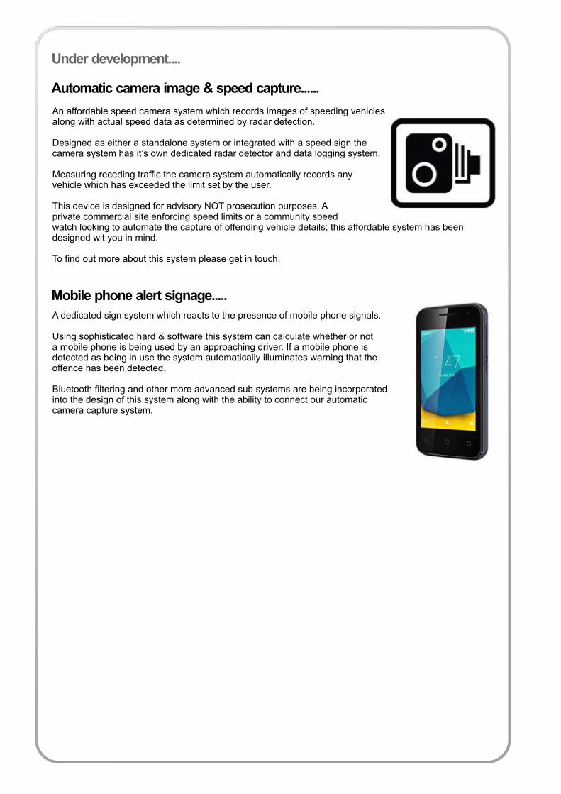
Under development....
Automatic camera image & speed capture......
Mobile phone alert signage.....
An affordable speed camera system which records images of speeding vehiclesalong with actual speed data as determined by radar detection.
Designed as either a standalone system or integrated with a speed sign the camera system has it’s own dedicated radar detector and data logging system.
Measuring receding traffic the camera system automatically records any vehicle which has exceeded the limit set by the user.
This device is designed for advisory NOT prosecution purposes. A private commercial site enforcing speed limits or a community speed watch looking to automate the capture of offending vehicle details; this affordable system has beendesigned wit you in mind.
To find out more about this system please get in touch.
A dedicated sign system which reacts to the presence of mobile phone signals.
Using sophisticated hard & software this system can calculate whether or nota mobile phone is being used by an approaching driver. If a mobile phone isdetected as being in use the system automatically illuminates warning that theoffence has been detected.
Bluetooth filtering and other more advanced sub systems are being incorporatedinto the design of this system along with the ability to connect our automaticcamera capture system.

SmartGr upSmartGr upM A N U F A C T U R I N G
CNC Waterjet profiling
CNC Laser cutting
CNC Routing
MiG & TiG Welding
Powder Coating
Wet Spraying
Plastic forming & moulding
PCB design
PCB assembly
Software development
13 The Glenmore Centre, Old Brickyard Road, Sandleheath, Fordingbridge,Hampshire. SP6 1TE.
01425 656 143 0800 413 892 [email protected]
General terms & conditions and speed sign warranty terms & conditions available on request.Copyright Sg Manufacturing 2019
Copyright SG Manufacturing 2019
Accredited to ISO 9001Qua l i t y AssuranceS T A N D A R D S
On site engineeringsupport available....
Always ready to help!
Proud suppliers to some of the biggest companies in Britain
Installation
Servicing
Training
0800 413 892