Embed Size (px)
Citation preview
Layer 3 12-Port 10G SFP+ + 8-Port 10/100/1000T
Managed Switch with Dual 100~240V AC Redundant Power
XGS-6350-12X8TR
Quick Installation Guide
Table of Contents
1. Package Contents ....................................................................................... 3
2. Switch Management .................................................................................... 4
3. Requirements ............................................................................................. 5
4. Terminal Setup ........................................................................................... 6
4.1 Logon to the Console ........................................................................... 7
4.2 ConfiguringIPAddress ......................................................................... 7
4.3 Setting100BASE-TXforGigabitEthernetPort ........................................ 9
4.4 Setting1000BASE-XforSFP+Port ........................................................ 9
4.5 ChangingPassword .............................................................................10
4.6 SavingtheConfiguration .....................................................................10
5. StartingWebManagement .........................................................................11
5.1 LoggingintotheManagedSwitch .......................................................12
5.2 SavingConfigurationviatheWeb ........................................................13
6. RecoveringBacktoDefaultConfiguration .....................................................14
7. Customer Support .....................................................................................15
3
1. Package ContentsThank you for purchasing PLANET Layer 3 12-Port 10G SFP+ + 8-Port10/100/1000TManagedSwitch,XGS-6350-12X8TR.
Unless specified, “Managed Switch” mentioned in this Quick Installation GuidereferstotheXGS-6350-12X8TR.
Open the box of theManaged Switch and carefully unpack it. The box shouldcontainthefollowingitems:
z TheManagedSwitchx1
z QuickInstallationGuidex1
z RJ45-to-DB9ConsoleCablex1
z PowerCordx2
z RubberFeetx4
z TwoRack-mountingBracketswithAttachmentScrewsx6
z SFPDustCapx12(installedonthemachine)
If any item is found missing or damaged, please contact your local reseller forreplacement.
4
2. Switch ManagementTo set up the Managed Switch, the user needs to configure the Managed Switchfornetworkmanagement.TheManagedSwitchprovidestwomanagementoptions:Out-of-Band ManagementandIn-Band Management.
Out-of-Band ManagementOut-of-band management is the management through console interface.Generally, the user will use out-of-band management for the initial switch configuration,orwhenin-bandmanagementisnotavailable.
Important
TheManaged Switch is shippedwith IP address 192.168.0.254/24assigned by default. User can assign another IP address to theManaged Switch via the console interface to be able to remotelyaccesstheManagedSwitchthroughTelnetorHTTP.
In-Band ManagementIn-band management refers to the management by logging in to the ManagedSwitchusingTelnetorHTTP,orusingSNMPmanagementsoftwaretoconfiguretheManaged Switch. In-bandmanagement enables themanagement of theManagedSwitchtoattachsomedevicestotheSwitch.Thefollowingproceduresarerequiredtoenablein-bandmanagement:
1. Logon to console
2.Assign/ConfigureIPaddress
3. Create a remote login account
4.EnableHTTPorTelnetserverontheManagedSwitch
In case in-bandmanagement fails due to Managed Switch configuration changes,out-of-bandmanagement canbeused for configuringandmanaging theManagedSwitch.
5
3. Requirements z Workstations runningWindows XP/2003/Vista/2008/7/8/10, MAC OS X or later,Linux,UNIX,orotherplatformsarecompatiblewithTCP/IPprotocols.
z WorkstationsareinstalledwithEthernetNIC(NetworkInterfaceCard)
z SerialPortConnection(Terminal)
The above Workstations come with COM Port (DB9) or USB-to-RS232converter.
The aboveWorkstations have been installed with terminal emulator, such asTera Term or PuTTY.
Serial cable -- one end is attached to theRS232 serial port,while the otherendtotheconsoleportoftheManagedSwitch.
z EthernetPortConnection
Networkcables--Usestandardnetwork(UTP)cableswithRJ45connectors.
The above PC is installed with Web browser and JAVA runtime environmentplug-in.
Note
It isrecommendedtouseInternetExplorer8.0orabovetoaccessthe Managed Switch. If theWeb interface of the Managed Switchis not accessible, please turn off the anti-virus software or firewallandthentryitagain.
6
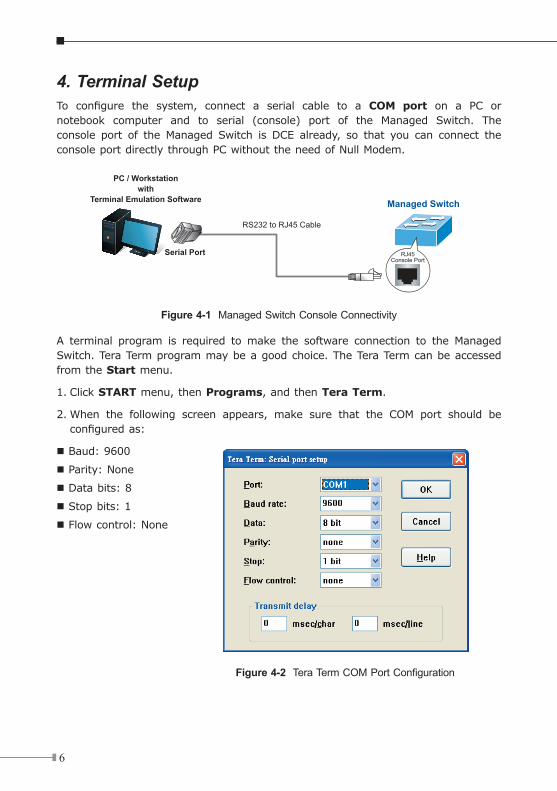
4. Terminal SetupTo configure the system, connect a serial cable to a COM port on a PC or notebook computer and to serial (console) port of the Managed Switch. Theconsole port of theManaged Switch is DCE already, so that you can connect theconsoleportdirectlythroughPCwithouttheneedofNullModem.
Managed Switch
PC / Workstationwith
Terminal Emulation Software
Serial Port
RS232 to RJ45 Cable
Console PortRJ45
Figure 4-1 Managed Switch Console Connectivity
A terminal program is required tomake the software connection to the ManagedSwitch.TeraTermprogrammaybeagoodchoice.TheTeraTermcanbeaccessedfromtheStart menu.
1. Click STARTmenu,thenPrograms,andthenTera Term.
2.When the following screen appears, make sure that the COM port should beconfiguredas:
Baud:9600
Parity:None
Databits:8
Stopbits:1
Flowcontrol:None
Figure 4-2 Tera Term COM Port Configuration
7
4.1 Logon to the ConsoleOnce the terminal is connected to thedevice,poweron theManagedSwitch,andtheterminalwilldisplay“running testing procedures”.
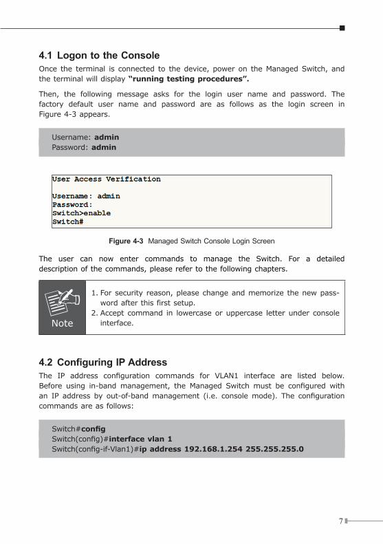
Then, the following message asks for the login user name and password. Thefactory default user name and password are as follows as the login screen inFigure4-3appears.
Username:adminPassword:admin
Figure 4-3 Managed Switch Console Login Screen
The user can now enter commands to manage the Switch. For a detaileddescriptionofthecommands,pleaserefertothefollowingchapters.
Note
1.Forsecurity reason,pleasechangeandmemorize thenewpass-wordafterthisfirstsetup.
2.Accept command in lowercaseoruppercase letterunder consoleinterface.
4.2 ConfiguringIPAddressThe IP address configuration commands for VLAN1 interface are listed below.Before using in-bandmanagement, the Managed Switchmust be configured withan IP address by out-of-bandmanagement (i.e. consolemode). The configurationcommandsareasfollows:
Switch#configSwitch(config)#interface vlan 1Switch(config-if-Vlan1)#ip address 192.168.1.254 255.255.255.0
8
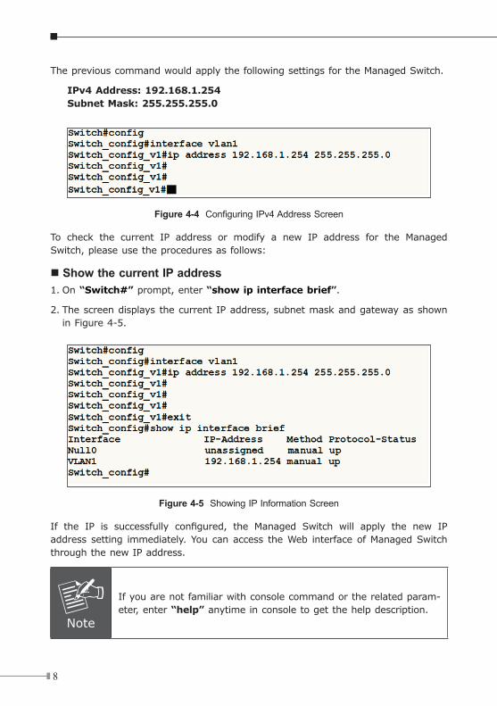
ThepreviouscommandwouldapplythefollowingsettingsfortheManagedSwitch.
IPv4 Address: 192.168.1.254Subnet Mask: 255.255.255.0
Figure 4-4 Configuring IPv4 Address Screen
To check the current IP address or modify a new IP address for the ManagedSwitch,pleaseusetheproceduresasfollows:
Show the current IP address1. On “Switch#”prompt,enter“show ip interface brief”.
2.ThescreendisplaysthecurrentIPaddress,subnetmaskandgatewayasshowninFigure4-5.
Figure 4-5 Showing IP Information Screen
If the IP is successfully configured, the Managed Switch will apply the new IPaddresssetting immediately.Youcanaccess theWeb interfaceofManagedSwitchthroughthenewIPaddress.
Note
Ifyouarenotfamiliarwithconsolecommandortherelatedparam-eter,enter“help”anytimeinconsoletogetthehelpdescription.
9
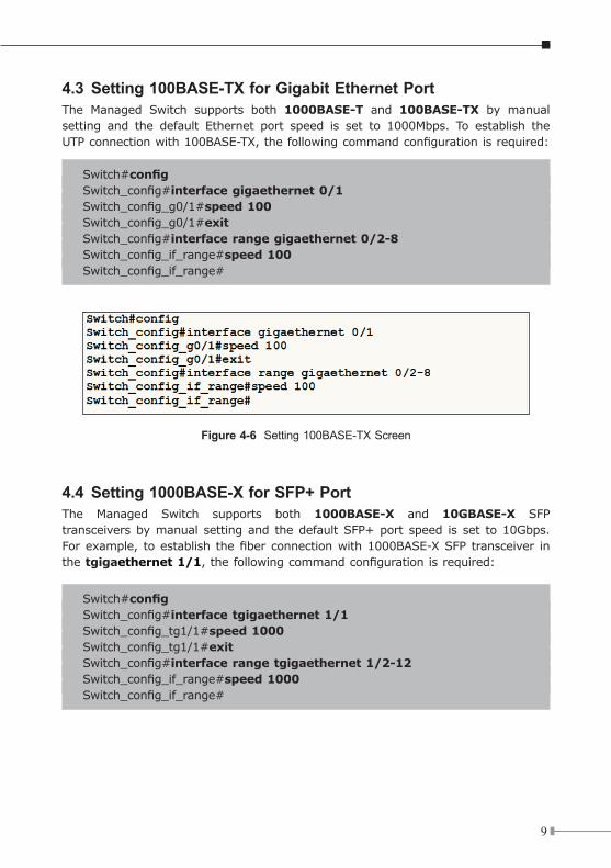
4.3 Setting 100BASE-TX for Gigabit Ethernet PortThe Managed Switch supports both 1000BASE-T and 100BASE-TX by manualsetting and the default Ethernet port speed is set to 1000Mbps. To establish theUTPconnectionwith100BASE-TX,thefollowingcommandconfigurationisrequired:
Switch#configSwitch_config#interface gigaethernet 0/1Switch_config_g0/1#speed 100Switch_config_g0/1#exitSwitch_config#interface range gigaethernet 0/2-8Switch_config_if_range#speed 100Switch_config_if_range#
Figure 4-6 Setting 100BASE-TX Screen
4.4 Setting 1000BASE-X for SFP+ PortThe Managed Switch supports both 1000BASE-X and 10GBASE-X SFPtransceiversbymanual settingand thedefaultSFP+port speed is set to10Gbps.Forexample, toestablish thefiberconnectionwith1000BASE-XSFPtransceiver inthe tgigaethernet 1/1,thefollowingcommandconfigurationisrequired:
Switch#configSwitch_config#interface tgigaethernet 1/1Switch_config_tg1/1#speed 1000Switch_config_tg1/1#exitSwitch_config#interface range tgigaethernet 1/2-12Switch_config_if_range#speed 1000Switch_config_if_range#
10
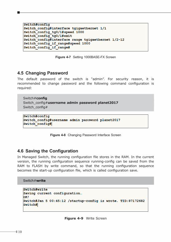
Figure 4-7 Setting 1000BASE-FX Screen
4.5 Changing PasswordThe default password of the switch is “admin”. For security reason, it isrecommended to change password and the following command configuration isrequired:
Switch#configSwitch_config#username admin password planet2017Switch_config#
Figure 4-8 Changing Password Interface Screen
4.6 SavingtheConfigurationInManagedSwitch,therunningconfigurationfilestoresintheRAM.Inthecurrentversion, the running configuration sequence running-config canbe saved from theRAM to FLASH by write command, so that the running configuration sequencebecomesthestart-upconfigurationfile,whichiscalledconfigurationsave.
Switch#write
Figure 4-9 Write Screen
11
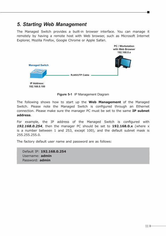
5. Starting Web ManagementThe Managed Switch provides a built-in browser interface. You can manage itremotely by having a remote host with Web browser, such as Microsoft InternetExplorer,MozillaFirefox,GoogleChromeorAppleSafari.
PC / Workstationwith Web Browser
192.168.0.x
Managed Switch
RJ45/UTP Cable
IP Address:192.168.0.100
Figure 5-1 IP Management Diagram
The following shows how to start up the Web Management of the ManagedSwitch. Please note the Managed Switch is configured through an Ethernetconnection.PleasemakesurethemanagerPCmustbesettothesameIP subnet address.
For example, the IP address of the Managed Switch is configured with192.168.0.254, then the manager PC should be set to 192.168.0.x (where xis a number between 1 and 253, except 100), and the default subnet mask is255.255.255.0.
Thefactorydefaultusernameandpasswordareasfollows:
DefaultIP:192.168.0.254Username:adminPassword:admin
12
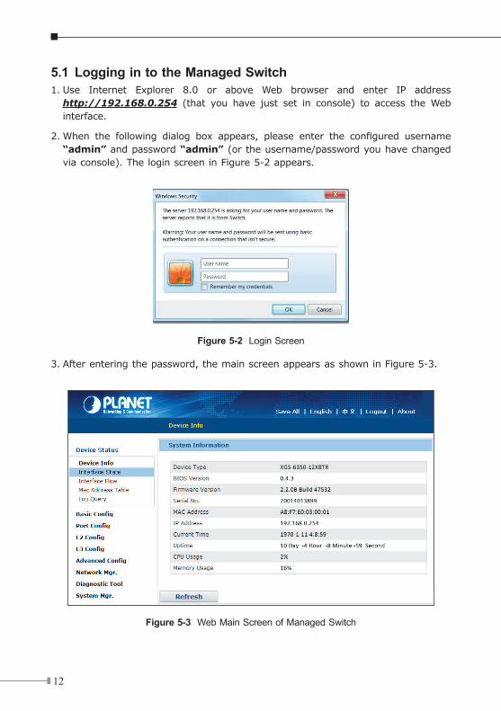
5.1 Logging in to the Managed Switch1.Use Internet Explorer 8.0 or above Web browser and enter IP address
http://192.168.0.254 (that you have just set in console) to access theWebinterface.
2.When the following dialog box appears, please enter the configured username“admin” andpassword“admin”(ortheusername/passwordyouhavechangedviaconsole).TheloginscreeninFigure5-2appears.
Figure 5-2 Login Screen
3.Afterenteringthepassword,themainscreenappearsasshowninFigure5-3.
Figure 5-3 Web Main Screen of Managed Switch
13
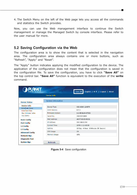
4.TheSwitchMenuonthe leftoftheWebpage letsyouaccessall thecommandsandstatisticstheSwitchprovides.
Now, you can use the Web management interface to continue the Switchmanagementormanage theManagedSwitchby console interface.Please refer totheusermanualformore.
5.2 SavingConfigurationviatheWebThe configuration area is to show the content that is selected in the navigationarea. The configuration area always contains one or more buttons, such as“Refresh”,“Apply”and“Reset”.
The“Apply”buttonindicatesapplyingthemodifiedconfigurationtothedevice.Theapplication of the configuration does not mean that the configuration is saved inthe configuration file. To save the configuration, you have to click “Save All” on thetopcontrolbar.“Save All”functionisequivalenttotheexecutionofthewrite command.
Figure 5-4 Save configuration

14
6.RecoveringBacktoDefaultConfiguration IP address has been changed or admin password has been forgottenTo reset the IP address to the default IP address “192.168.0.254” or reset the login password to default value, press the hardware reset button on the frontpanel for about 5 seconds. After the device is rebooted, you can login themanagementWebinterfacewithinthesamesubnetof192.168.0.xx.
G4G2
G1 G3XGS-6350-12X8TR
ResetSYS
9600, N, 8, 1
Console
PWR
G4
G3
G2
G1
G8
G7
G6
G5
TE4
TE3
TE2
TE1
TE8
TE7
TE6
TE5
TE12
TE11
TE10
TE9
ACTLNK
10G
Figure 6-1 XGS-6350-12X8TR Reset Button
15
7. Customer SupportThank you for purchasing PLANET products. You can browse our online FAQresourceat thePLANETWeb sitefirst to check if it could solveyour issue. If youneedmoresupportinformation,pleasecontactPLANETswitchsupportteam.
PLANETonlineFAQs:http://www.planet.com.tw/en/support/faq.php?type=1
Switchsupportteammailaddress:[email protected]
XGS-6350-12X8TRUser’sManualhttp://www.planet.com.tw/en/support/download.php?view=3&key=XGS-6350-12X8TR#list
Copyright © PLANET Technology Corp. 2017.Contents are subject to revision without prior notice.PLANET is a registered trademark of PLANET Technology Corp. All other trademarks belong to their respective owners.