Embed Size (px)
Citation preview
Quick Reference Guide for the Smart Distributed System Bus
and Troubleshooting Procedures
Quick R
eference Guide for the S
mart D
istributed System
Bus

Reference Guide
2 Honeywell l MICRO SWITCH Sensing and Control
Information in this manual is subject to change without notice and does not represent a commit-ment on the part of Honeywell MICRO SWITCH. No part of this manual may be reproduced or transmitted in any form or by any means, elec-tronic, mechanical, photocopying, recording, or otherwise, without prior written permission of Honeywell MICRO SWITCH.
TRADEMARKS
Commercial names of products from partner man-ufacturers or developers that appear in this manual are registered or unregistered trademarks of those respective manufacturers or developers, which have expressed neither approval or disapproval of Honeywell products.
Document Number PK 80062 Issue 1
Copyright Honeywell, Inc. 1998. All rights reserved. Simultaneously published in the U.S. and Canada. Printed in the United States of America.
ý :$51,1*PERSONAL INJURY
DO NOT USE these products as safety or emergency stop devices, or in any other application where failure of the product could result in personal injury.
Failure to comply with these instructions could result in death or serious injury.
Issue 1 PK 80062
For application help: Call 1-800-537-6945 3
Tabl
e of
Con
tent
sChapter 1 IntroductionWhy Should You Read This? . . . . . . . . . . . . 1
Installation Guide Objectives . . . . . . . . . . . . 1Where This Guide Fits . . . . . . . . . . . . . . . . . . . 2
Conventions . . . . . . . . . . . . . . . . . . . . . . . . . . . 3
What is Smart Distributed System? . . . . . . . . . 5
Related Publications . . . . . . . . . . . . . . . . . . . 6
Warranty/Remedy . . . . . . . . . . . . . . . . . . . . . 6
Sales and Service . . . . . . . . . . . . . . . . . . . . . 7
Chapter 2 InstallationChapter Objectives . . . . . . . . . . . . . . . . . . . . 9The Installation Process . . . . . . . . . . . . . . . . . 11
Installation Planning . . . . . . . . . . . . . . . . . . . 12
Pre-Installation Check List. . . . . . . . . . . . . . . 13
Phase 1 — Install Components . . . . . . . . . . . 15
Three Cabling Schemes: . . . . . . . . . . . . . . . 22Phase 2 — Configure System . . . . . . . . . . . . 35
Phase 3 — Commission System . . . . . . . . . . 41
Commissioning Checklist Summary . . . . . . . 52
Chapter 3 Troubleshooting GuideChapter Objectives . . . . . . . . . . . . . . . . . . . 55Network Troubleshooting . . . . . . . . . . . . . . . 56
To isolate a problem on the network: . . . . . 56
Case Histories . . . . . . . . . . . . . . . . . . . . . . . 75
Chapter 4 ReferenceChapter Objectives . . . . . . . . . . . . . . . . . . . 77
Commonly Used Terms . . . . . . . . . . . . . . . 77Topology . . . . . . . . . . . . . . . . . . . . . . . . . . . . 82
Cables. . . . . . . . . . . . . . . . . . . . . . . . . . . . . . . 83
Physical Specifications . . . . . . . . . . . . . . . . . 84
Plan Your Application . . . . . . . . . . . . . . . . . . 85

Reference Guide
4 Honeywell l MICRO SWITCH Sensing and Control
Table of C
ontents
Cable Catalog Listings . . . . . . . . . . . . . . . . 89
Sales and Service . . . . . . . . . . . . . . . . . . . 125

Issue 1 PK 80062
For application help: Call 1-800-537-69451
Intr
oduc
tion
Chapter 1Introduction
Why Should You Read This?
This Reference Guide provides information that will help you install, verify, and troubleshoot your Smart Distributed System network. Use steps out-lined in this guide to safeguard your system and equipment from problems that may hinder its operation or even damage components.
Installation Guide Objectives
This publication illustrates and explains how to install a Smart Distributed System network. It covers:
What you need to successfully complete the installation.
How to install your physical media and devices. How to configure your system. How to check and document your system. How to troubleshoot after installation.

Reference Guide
2 Honeywell l MICRO SWITCH Sensing and Control
Introduction
Where This Guide Fits
The structure of this guide is as follows. In gen-eral, you’ll find graphics, illustrations, and quick reference steps on left-hand pages while textual descriptions appear on the right.
This chapter, Introduction, provides general infor-mation about this guide plus a brief introduction to the Smart Distributed System architecture.
We assume that you or someone in your organiza-tion has completed a thorough planning phase including needs analysis and system design.
If you don’t have a complete system design, refer to Plan Your Application on page 85 for a sum-mary of steps you should take before installing your network.
Chapter 2, Installation, begins with a summary of the pre-installation planning requirements that go into a complete system design. The remainder of that chapter describes steps required to success-fully install the network and all its connected devices. The chapter provides a checklist to get your system working the first time.
Chapter 3, Troubleshooting Guide, gives you a process to use to track down the cause of problems.
Chapter 4, Reference, brings together key refer-ence material from various documents.
Issue 1 PK 80062
For application help: Call 1-800-537-69453
Intr
oduc
tion
Conventions
This guide includes symbols to identify important information.
The Notice symbol indicates essential information of special interest or importance that will aid in, or simplify job performance.
Tips identify helpful information about a process, situation, or concept. A tip may also include shortcuts or alternative methods.
ý :$51,1*PERSONAL INJURY
Warnings identify critical information about a process or situation that has the potential to cause component or system damage, economic loss, personal injury, or even death.
Failure to comply with these instructions could result in death or serious injury.
Reference Guide
4 Honeywell l MICRO SWITCH Sensing and Control
Introduction
PowerSupply
ControllersDevices
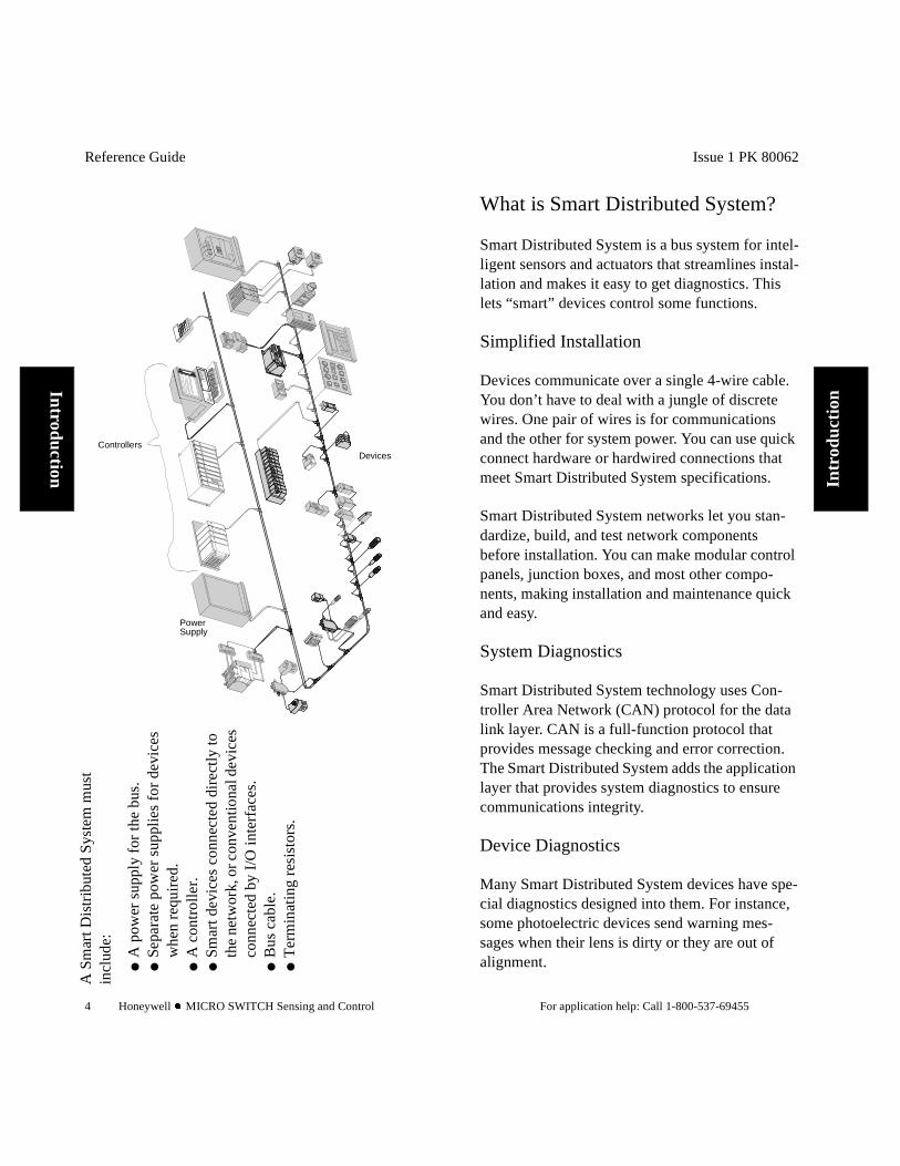
A S
mar
t Dis
trib
uted
Sys
tem
mus
t in
clud
e:
A
pow
er s
uppl
y fo
r th
e bu
s.
Sepa
rate
pow
er s
uppl
ies
for
devi
ces
whe
n re
quir
ed.
A
con
trol
ler.
Sm
art d
evic
es c
onne
cted
dir
ectl
y to
th
e ne
twor
k, o
r con
vent
iona
l dev
ices
co
nnec
ted
by I
/O in
terf
aces
.
Bus
cab
le.
T
erm
inat
ing
resi
stor
s.
Issue 1 PK 80062
For application help: Call 1-800-537-69455
Intr
oduc
tion
What is Smart Distributed System?
Smart Distributed System is a bus system for intel-ligent sensors and actuators that streamlines instal-lation and makes it easy to get diagnostics. This lets “smart” devices control some functions.
Simplified Installation
Devices communicate over a single 4-wire cable. You don’t have to deal with a jungle of discrete wires. One pair of wires is for communications and the other for system power. You can use quick connect hardware or hardwired connections that meet Smart Distributed System specifications.
Smart Distributed System networks let you stan-dardize, build, and test network components before installation. You can make modular control panels, junction boxes, and most other compo-nents, making installation and maintenance quick and easy.
System Diagnostics
Smart Distributed System technology uses Con-troller Area Network (CAN) protocol for the data link layer. CAN is a full-function protocol that provides message checking and error correction. The Smart Distributed System adds the application layer that provides system diagnostics to ensure communications integrity.
Device Diagnostics
Many Smart Distributed System devices have spe-cial diagnostics designed into them. For instance, some photoelectric devices send warning mes-sages when their lens is dirty or they are out of alignment.

Reference Guide
6 Honeywell l MICRO SWITCH Sensing and Control
Introduction
Related Publications
Warranty/Remedy
Honeywell warrants goods of its manufacture as being free of defective materials and faulty work-manship. Commencing with date of shipment, Honeywell’s warranty runs for 18 months. If war-ranted goods are returned to Honeywell during that period of coverage, Honeywell will repair or replace without charge those items it finds defec-tive. The foregoing is Buyer’s sole remedy and is in lieu of all other warranties, express or implied, including those of merchantability and fitness for particular purpose.
Table 1:
For Information About See Publication
CAN Bosch V2.0 CANISO Standard 11898
Smart Distributed System Physical Layer Specification
GS 052 104
Issue 1 PK 80062
For application help: Call 1-800-537-69457
Intr
oduc
tion
Sales and Service
Honeywell serves its customers through a world-wide network of sales offices and distributors. Contact a nearby sales office for application assis-tance, current specifications, pricing, or the name of the nearest authorized distributor.
Or contact:
MICRO SWITCH
Honeywell, Inc.11 W. Spring StreetFreeport, Illinois 61032For application assistance:1-800-537-6945 USA1-800-737-3360 Canada1-815-235-6847 International
INTERNET E-MAIL [email protected]
INTERNET WORLD WIDE WEB ADDRESSEShttp://www.honeywell.com/sensing/http://www.honeywell.com/sensing/sds
While we provide application assistance for Honeywell products, personally and through our literature, it is up to the customer to determine the suitability of the product in the application.

Reference Guide
8 Honeywell l MICRO SWITCH Sensing and Control
Introduction

Issue 1 PK 80062
For application help: Call 1-800-537-6945 9
Inst
alla
tion
Chapter 2Installation
Chapter Objectives
This chapter:
Shows the three phases of installation and provides detailed steps for each phase.
Lists tools and supplies you need to install a Smart Distributed System network.
Explains the steps you must follow to properly and safely install a system.
Reference Guide
10 Honeywell l MICRO SWITCH Sensing and Control
Installation
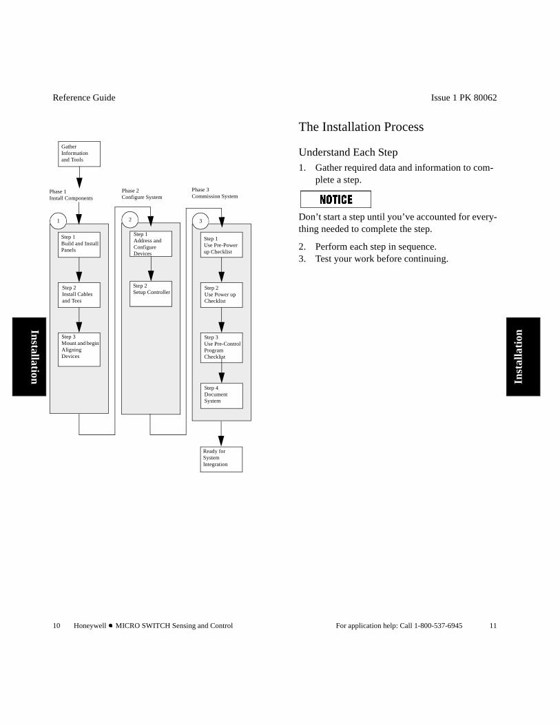
Gather Information and Tools
Phase 1Install Components
Phase 2Configure System
Phase 3Commission System
Step 2Use Power up Checklist
Step 3Use Pre-Control Program Checklist
Step 1Use Pre-Power up Checklist
Ready for System Integration
3
Step 4Document System
Step 1Build and Install Panels
Step 2Install Cables and Tees
Step 1Address and Configure Devices
Step 2Setup Controller
1 2
Step 3Mount and begin Aligning Devices
Issue 1 PK 80062
For application help: Call 1-800-537-6945 11
Inst
alla
tion
The Installation Process
Understand Each Step1. Gather required data and information to com-
plete a step.
Don’t start a step until you’ve accounted for every-thing needed to complete the step.
2. Perform each step in sequence.3. Test your work before continuing.
Reference Guide
12 Honeywell l MICRO SWITCH Sensing and Control
Installation
Installation Planning Be familiar with Smart Distributed System
technology (see Commonly Used Terms on page 77).
Be familiar with your application. Gather pre-installation system documentation
from the system designer. Gather manufacturer documentation for all
devices.
Issue 1 PK 80062
For application help: Call 1-800-537-6945 13
Inst
alla
tion
Pre-Installation Check List
Before you attempt installation, someone in your organization should have completed a thorough plan, needs analysis, and system design. This doc-ument assumes that you, or another team of engi-neers, have completed these pre-installation steps. For reference, your pre-installation plan should include:
Detailed system and machine layout. Detailed bus layout including routing, cable
lengths, and device and branch locations. Manufacturer’s documentation for each device
on the bus. Detailed list of device power requirements. Control panel (power supply) layout and wiring
diagram.
If you don’t have a complete system design, refer to Plan Your Application on page 85 for a sum-mary of steps you should take before installing your network.
Reference Guide
14 Honeywell l MICRO SWITCH Sensing and Control
Installation
Step 1Build and Install Panels
Step 2Install Cables and Tees
Step 3Mount and begin Aligning Devices
1
Phase 1Install Components
Issue 1 PK 80062
For application help: Call 1-800-537-6945 15
Inst
alla
tion
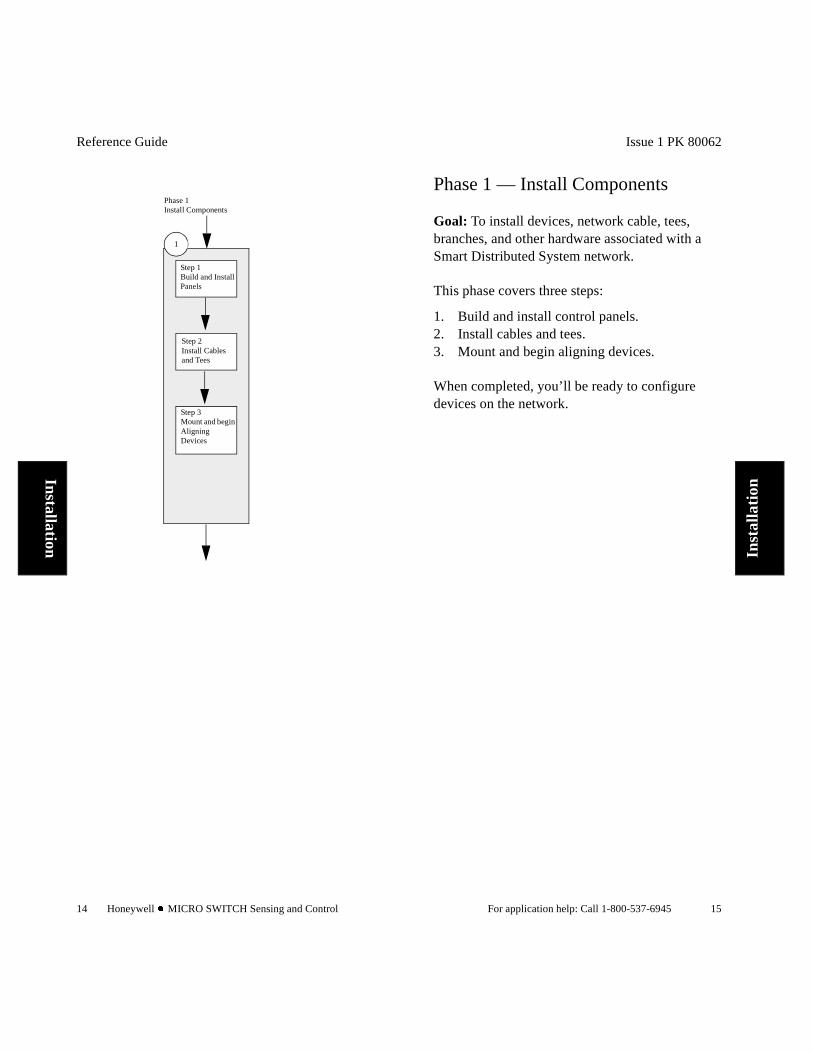
Phase 1 — Install Components
Goal: To install devices, network cable, tees, branches, and other hardware associated with a Smart Distributed System network.
This phase covers three steps:
1. Build and install control panels.2. Install cables and tees.3. Mount and begin aligning devices.
When completed, you’ll be ready to configure devices on the network.
Reference Guide
16 Honeywell l MICRO SWITCH Sensing and Control
Installation
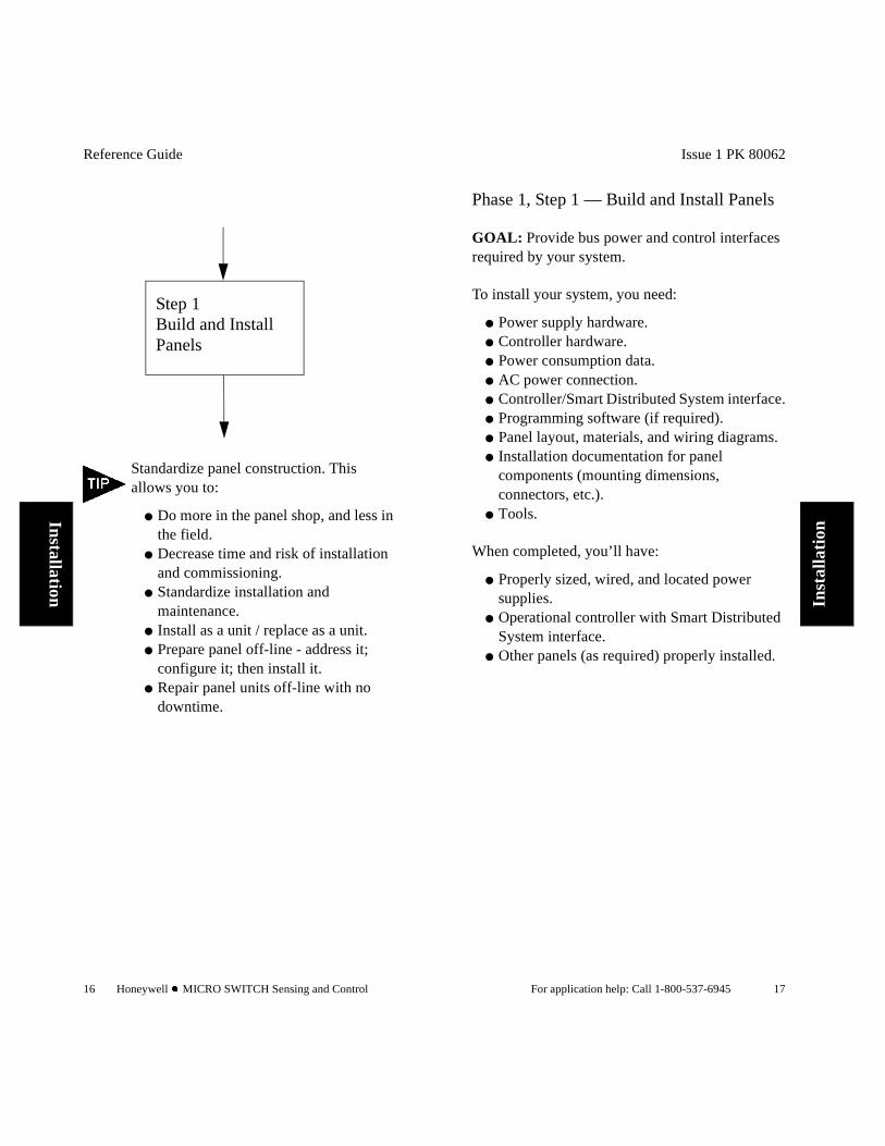
Step 1Build and Install Panels
Standardize panel construction. This allows you to:
Do more in the panel shop, and less in the field.
Decrease time and risk of installation and commissioning.
Standardize installation and maintenance.
Install as a unit / replace as a unit. Prepare panel off-line - address it;
configure it; then install it. Repair panel units off-line with no
downtime.
Issue 1 PK 80062
For application help: Call 1-800-537-6945 17
Inst
alla
tion
Phase 1, Step 1 — Build and Install Panels
GOAL: Provide bus power and control interfaces required by your system.
To install your system, you need:
Power supply hardware. Controller hardware. Power consumption data. AC power connection. Controller/Smart Distributed System interface. Programming software (if required). Panel layout, materials, and wiring diagrams. Installation documentation for panel
components (mounting dimensions, connectors, etc.).
Tools.
When completed, you’ll have:
Properly sized, wired, and located power supplies.
Operational controller with Smart Distributed System interface.
Other panels (as required) properly installed.
Reference Guide
18 Honeywell l MICRO SWITCH Sensing and Control
Installation
To 1
20 V
AC
Circ
uit
Bre
aker
120
V 1
A
Inpu
t
+24
VD
C (
Blu
e)
-24
VD
C (
Bro
wn)
Hon
eyw
ell B
ulkh
ead
Cab
le (
SD
S-B
KH
D)
3" s
epar
atio
n be
twee
nA
C a
nd D
C p
ower
wiri
ng
FU
SE
Typ.
6A
32
VD
CTy
pe A
GC
-6
Shi
eld
PO
WE
RS
UP
PLY
24 V
DC
6A
(Typ
ical
)
The
fus
e pr
otec
ts c
abli
ng u
nder
nor
mal
ope
rati
ng
cond
itio
ns, a
nd h
elps
avo
id in
term
itte
nt p
robl
ems.
It
wil
l blo
w w
hen
dete
ctin
g a
“har
d sh
ort
,” w
hic
h
can
ha
ppen
if d
evi
ce w
ires
are
acc
ide
ntly
cu
t.
Att
ach
the
shi
eld
wir
e t
o ea
rth
grou
nd in
the
pow
er
supp
ly c
abin
et.
Clip
Exp
ose
d sh
ield
wir
e ba
ck t
o t
he s
heat
hin
g a
t ea
ch d
evi
ce.
ý:$5
1,1*
P
ER
SO
NA
L IN
JUR
Y
Sel
ect t
he p
owe
r su
pply
, AC
wir
ing
, and
cir
cuit
brea
ker
in a
cco
rdan
ce a
ll a
pplic
abl
e c
ode
s an
d p
ract
ice
s.F
ailu
re t
o co
mpl
y w
ith
thes
e in
stru
ctio
ns c
ould
res
ult
in d
eath
or
seri
ous
inju
ry.
Issue 1 PK 80062
For application help: Call 1-800-537-6945 19
Inst
alla
tion
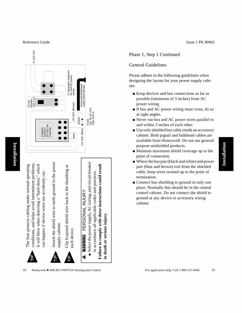
Phase 1, Step 1 Continued
General Guidelines
Please adhere to the following guidelines when designing the layout for your power supply cabi-net:
Keep devices and bus connections as far as possible (minimum of 3 inches) from AC power wiring.
If bus and AC power wiring must cross, do so at right angles.
Never run bus and AC power wires parallel to and within 3 inches of each other.
Use only shielded bus cable inside an accessory cabinet. Both pigtail and bulkhead cables are available from Honeywell. Do not use general purpose unshielded products.
Maintain maximum shield coverage up to the point of connection.
Where the bus pair (black and white) and power pair (blue and brown) exit from the shielded cable, keep wires twisted up to the point of termination.
Connect bus shielding to ground in only one place. Normally this should be in the central control cabinet. Do not connect the shield to ground at any device or accessory wiring cabinet.
Reference Guide
20 Honeywell l MICRO SWITCH Sensing and Control
Installation
24 v
olt
Line
ar B
usP
ower
Sup
ply
(Typ
ical
)
Fus
e:
Typ.
6A
32
VD
CTy
pe: A
GC
-6
To s
yste
mTo
PC
Bus
+
Bus
-
V +
V +
V -
V -
Shi
eld
Bla
ck
Whi
te
Bro
wn
Blu
e
Shi
eld
PC
Cab
le o
r
PC
- P
igta
il C
able
Bul
khea
dC
able
toS
yste
m
Con
trol
Cab
inetIssue 1 PK 80062
For application help: Call 1-800-537-6945 21
Inst
alla
tion
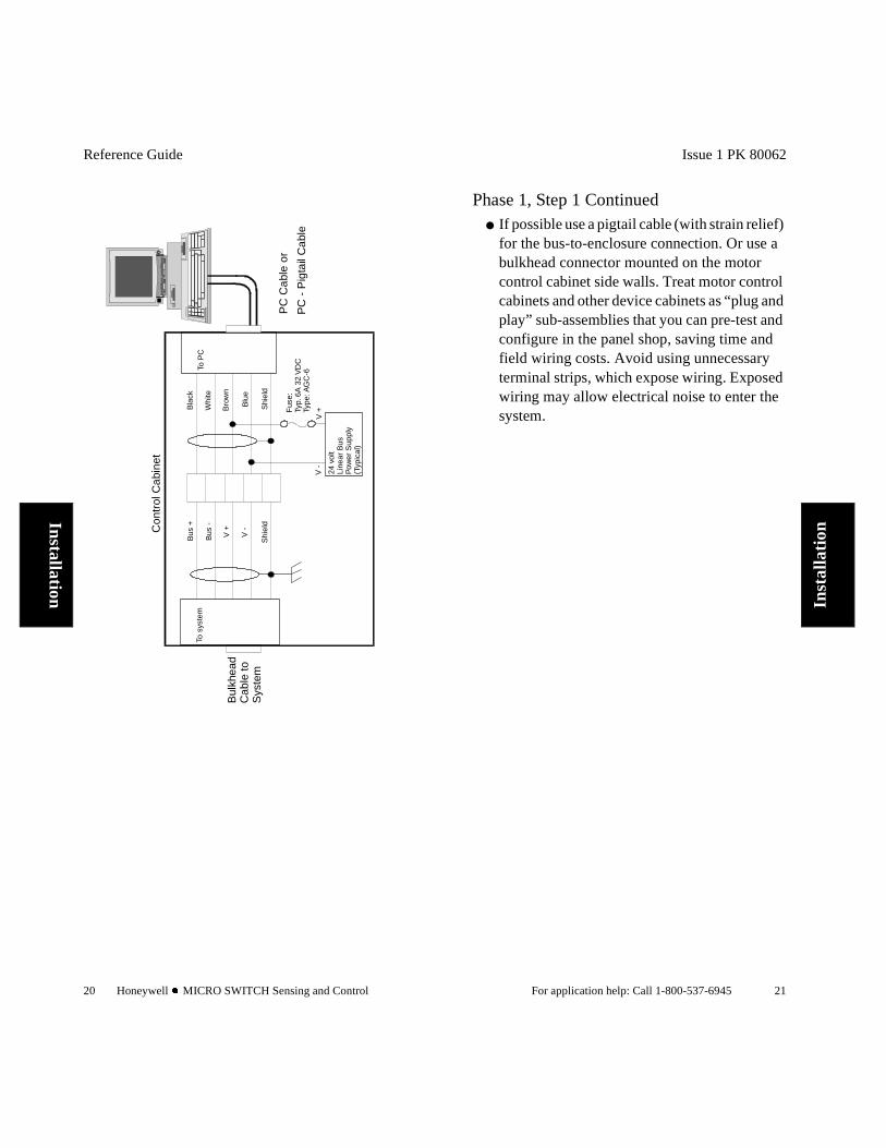
Phase 1, Step 1 Continued If possible use a pigtail cable (with strain relief)
for the bus-to-enclosure connection. Or use a bulkhead connector mounted on the motor control cabinet side walls. Treat motor control cabinets and other device cabinets as “plug and play” sub-assemblies that you can pre-test and configure in the panel shop, saving time and field wiring costs. Avoid using unnecessary terminal strips, which expose wiring. Exposed wiring may allow electrical noise to enter the system.
Reference Guide
22 Honeywell l MICRO SWITCH Sensing and Control
Installation
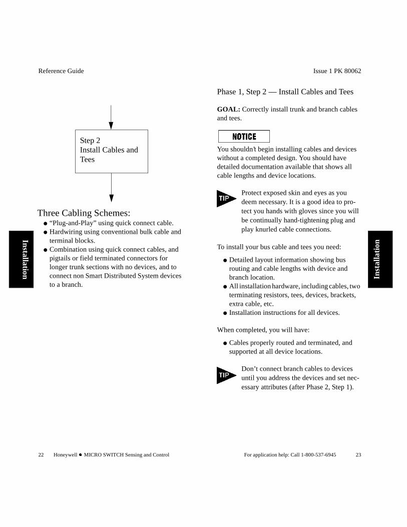
Step 2Install Cables and Tees
Three Cabling Schemes: “Plug-and-Play” using quick connect cable. Hardwiring using conventional bulk cable and
terminal blocks. Combination using quick connect cables, and
pigtails or field terminated connectors for longer trunk sections with no devices, and to connect non Smart Distributed System devices to a branch.
Issue 1 PK 80062
For application help: Call 1-800-537-6945 23
Inst
alla
tion
Phase 1, Step 2 — Install Cables and Tees
GOAL: Correctly install trunk and branch cables and tees.
You shouldn’t begin installing cables and devices without a completed design. You should have detailed documentation available that shows all cable lengths and device locations.
Protect exposed skin and eyes as you deem necessary. It is a good idea to pro-tect you hands with gloves since you will be continually hand-tightening plug and play knurled cable connections.
To install your bus cable and tees you need:
Detailed layout information showing bus routing and cable lengths with device and branch location.
All installation hardware, including cables, two terminating resistors, tees, devices, brackets, extra cable, etc.
Installation instructions for all devices.
When completed, you will have:
Cables properly routed and terminated, and supported at all device locations.
Don’t connect branch cables to devices until you address the devices and set nec-essary attributes (after Phase 2, Step 1).
Reference Guide
24 Honeywell l MICRO SWITCH Sensing and Control
Installation
POW
ER
SUPP
LY
CO
NT
RO
LL
ERTe
rmin
ator
(on
cont
rol
inte
rfac
e)
Pow
er S
uppl
y at
mid
poin
t of
elec
tric
allo
ad, P
C a
t end
. In
stal
l ter
min
atio
nju
mpe
r on
con
trol
inte
rfac
e.
Term
inat
or
POW
ER
SUPP
LYC
ON
TR
OL
LE
R
Term
inat
orTe
rmin
ator
Term
inat
or(o
n co
ntro
l int
erfa
ceha
s be
en d
isab
led)
Con
trol
ler
and
Pow
erSu
pply
loca
ted
sep-
arat
ely.
Ins
tall
term
-in
ator
s on
eac
h en
dof
bus
trun
k.
Issue 1 PK 80062
For application help: Call 1-800-537-6945 25
Inst
alla
tion
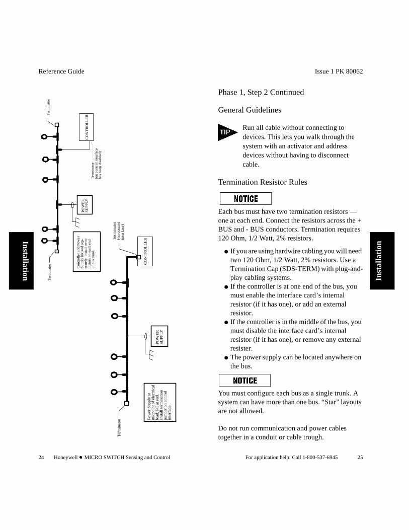
Phase 1, Step 2 Continued
General Guidelines
Run all cable without connecting to devices. This lets you walk through the system with an activator and address devices without having to disconnect cable.
Termination Resistor Rules
Each bus must have two termination resistors — one at each end. Connect the resistors across the + BUS and - BUS conductors. Termination requires 120 Ohm, 1/2 Watt, 2% resistors.
If you are using hardwire cabling you will need two 120 Ohm, 1/2 Watt, 2% resistors. Use a Termination Cap (SDS-TERM) with plug-and-play cabling systems.
If the controller is at one end of the bus, you must enable the interface card’s internal resistor (if it has one), or add an external resistor.
If the controller is in the middle of the bus, you must disable the interface card’s internal resistor (if it has one), or remove any external resister.
The power supply can be located anywhere on the bus.
You must configure each bus as a single trunk. A system can have more than one bus. “Star” layouts are not allowed.
Do not run communication and power cables together in a conduit or cable trough.
Reference Guide
26 Honeywell l MICRO SWITCH Sensing and Control
Installation
PO
WE
RSU
PPLY
CO
NT
RO
LL
ER
Term
inat
orTe
rmin
ator
Pow
er S
uppl
y an
dC
ontr
olle
r lo
cate
d in
cent
ral c
ontr
ol c
abin
et.
Kee
p po
wer
and
sig
nal
wir
es tw
iste
d an
d se
para
tefr
om A
C w
irin
g.
Term
inal
str
ip
Issue 1 PK 80062
For application help: Call 1-800-537-6945 27
Inst
alla
tion
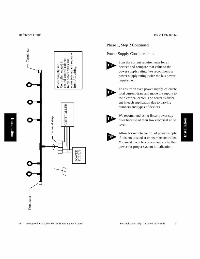
Phase 1, Step 2 Continued
Power Supply Considerations
Sum the current requirements for all devices and compare that value to the power supply rating. We recommend a power supply rating twice the bus power requirement.
To ensure an even power supply, calculate total current draw and move the supply to the electrical center. The center is differ-ent in each application due to varying numbers and types of devices.
We recommend using linear power sup-plies because of their low electrical noise level.
Allow for remote control of power supply if it is not located at or near the controller. You must cycle bus power and controller power for proper system initialization.
Reference Guide
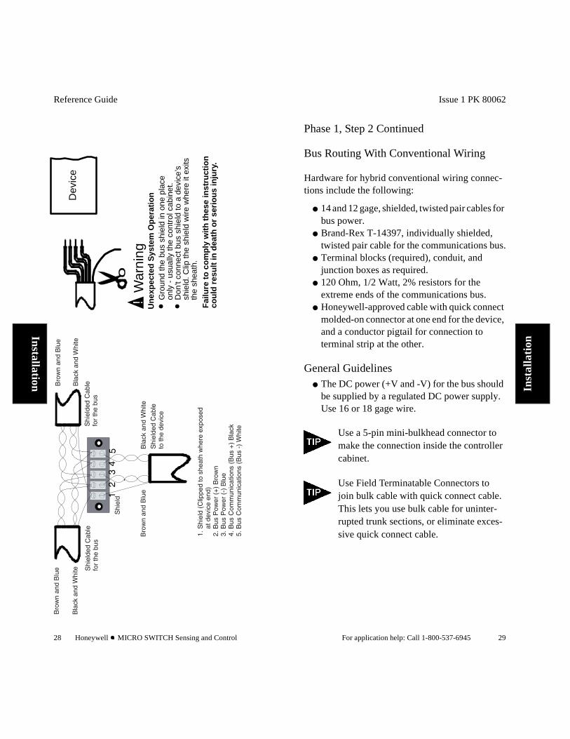
28 Honeywell l MICRO SWITCH Sensing and Control
Installation
Dev
ice
Gro
und
the
bus
shie
ld in
one
pla
ceon
ly -
usu
ally
the
cont
rol c
abin
et.
Don
’t co
nnec
t bus
shi
eld
to a
dev
ice’
ssh
ield
. Clip
the
shie
ld w
ire w
here
it e
xits
the
shea
th.
!W
arni
ngU
nex
pec
ted
Sys
tem
Op
erat
ion
Fai
lure
to
co
mp
ly w
ith
th
ese
inst
ruct
ion
cou
ld r
esu
lt in
dea
th o
r se
rio
us
inju
ry.
Issue 1 PK 80062
For application help: Call 1-800-537-6945 29
Inst
alla
tion
Phase 1, Step 2 Continued
Bus Routing With Conventional Wiring
Hardware for hybrid conventional wiring connec-tions include the following:
14 and 12 gage, shielded, twisted pair cables for bus power.
Brand-Rex T-14397, individually shielded, twisted pair cable for the communications bus.
Terminal blocks (required), conduit, and junction boxes as required.
120 Ohm, 1/2 Watt, 2% resistors for the extreme ends of the communications bus.
Honeywell-approved cable with quick connect molded-on connector at one end for the device, and a conductor pigtail for connection to terminal strip at the other.
General Guidelines The DC power (+V and -V) for the bus should
be supplied by a regulated DC power supply. Use 16 or 18 gage wire.
Use a 5-pin mini-bulkhead connector to make the connection inside the controller cabinet.
Use Field Terminatable Connectors to join bulk cable with quick connect cable. This lets you use bulk cable for uninter-rupted trunk sections, or eliminate exces-sive quick connect cable.
Reference Guide
30 Honeywell l MICRO SWITCH Sensing and Control
Installation
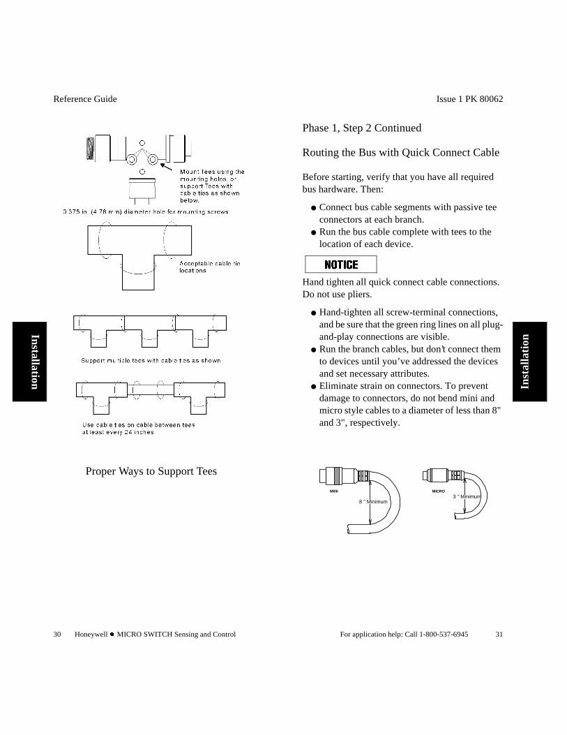
Proper Ways to Support Tees
Issue 1 PK 80062
For application help: Call 1-800-537-6945 31
Inst
alla
tion
Phase 1, Step 2 Continued
Routing the Bus with Quick Connect Cable
Before starting, verify that you have all required bus hardware. Then:
Connect bus cable segments with passive tee connectors at each branch.
Run the bus cable complete with tees to the location of each device.
Hand tighten all quick connect cable connections. Do not use pliers.
Hand-tighten all screw-terminal connections, and be sure that the green ring lines on all plug-and-play connections are visible.
Run the branch cables, but don’t connect them to devices until you’ve addressed the devices and set necessary attributes.
Eliminate strain on connectors. To prevent damage to connectors, do not bend mini and micro style cables to a diameter of less than 8" and 3", respectively.
3 " Minimum8 " Minimum
MINI MICRO
Reference Guide
32 Honeywell l MICRO SWITCH Sensing and Control
Installation
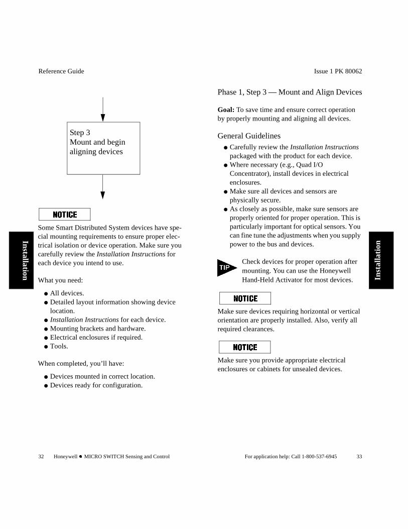
Step 3Mount and begin aligning devices
Some Smart Distributed System devices have spe-cial mounting requirements to ensure proper elec-trical isolation or device operation. Make sure you carefully review the Installation Instructions for each device you intend to use.
What you need:
All devices. Detailed layout information showing device
location. Installation Instructions for each device. Mounting brackets and hardware. Electrical enclosures if required. Tools.
When completed, you’ll have:
Devices mounted in correct location. Devices ready for configuration.
Issue 1 PK 80062
For application help: Call 1-800-537-6945 33
Inst
alla
tion
Phase 1, Step 3 — Mount and Align Devices
Goal: To save time and ensure correct operation by properly mounting and aligning all devices.
General Guidelines Carefully review the Installation Instructions
packaged with the product for each device. Where necessary (e.g., Quad I/O
Concentrator), install devices in electrical enclosures.
Make sure all devices and sensors are physically secure.
As closely as possible, make sure sensors are properly oriented for proper operation. This is particularly important for optical sensors. You can fine tune the adjustments when you supply power to the bus and devices.
Check devices for proper operation after mounting. You can use the Honeywell Hand-Held Activator for most devices.
Make sure devices requiring horizontal or vertical orientation are properly installed. Also, verify all required clearances.
Make sure you provide appropriate electrical enclosures or cabinets for unsealed devices.
Reference Guide
34 Honeywell l MICRO SWITCH Sensing and Control
Installation
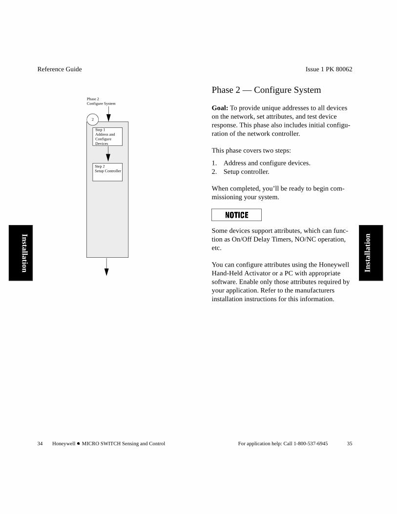
Phase 2Configure System
Step 1Address and Configure Devices
Step 2Setup Controller
2
Issue 1 PK 80062
For application help: Call 1-800-537-6945 35
Inst
alla
tion
Phase 2 — Configure System
Goal: To provide unique addresses to all devices on the network, set attributes, and test device response. This phase also includes initial configu-ration of the network controller.
This phase covers two steps:
1. Address and configure devices.2. Setup controller.
When completed, you’ll be ready to begin com-missioning your system.
Some devices support attributes, which can func-tion as On/Off Delay Timers, NO/NC operation, etc.
You can configure attributes using the Honeywell Hand-Held Activator or a PC with appropriate software. Enable only those attributes required by your application. Refer to the manufacturers installation instructions for this information.
Reference Guide
36 Honeywell l MICRO SWITCH Sensing and Control
Installation
Step 1Address and Configure Devices
To address and configure your devices, you need:
Address information for each device. Configuration required for each device. Hand-Held Activator (or PC and software). Installation Instructions for each device to
obtain device attribute defaults and determine appropriate settings.
Address labels.
When completed, you’ll have:
Devices correctly addressed. Device attributes set. Each device labeled for maintenance.
Issue 1 PK 80062
For application help: Call 1-800-537-6945 37
Inst
alla
tion
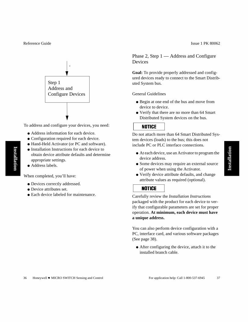
Phase 2, Step 1 — Address and Configure Devices
Goal: To provide properly addressed and config-ured devices ready to connect to the Smart Distrib-uted System bus.
General Guidelines
Begin at one end of the bus and move from device to device.
Verify that there are no more than 64 Smart Distributed System devices on the bus.
Do not attach more than 64 Smart Distributed Sys-tem devices (loads) to the bus; this does not include PC or PLC interface connections.
At each device, use an Activator to program the device address.
Some devices may require an external source of power when using the Activator.
Verify device attribute defaults, and change attribute values as required (optional).
Carefully review the Installation Instructions packaged with the product for each device to ver-ify that configurable parameters are set for proper operation. At minimum, each device must have a unique address.
You can also perform device configuration with a PC, interface card, and various software packages (See page 38).
After configuring the device, attach it to the installed branch cable.
Reference Guide
38 Honeywell l MICRO SWITCH Sensing and Control
Installation
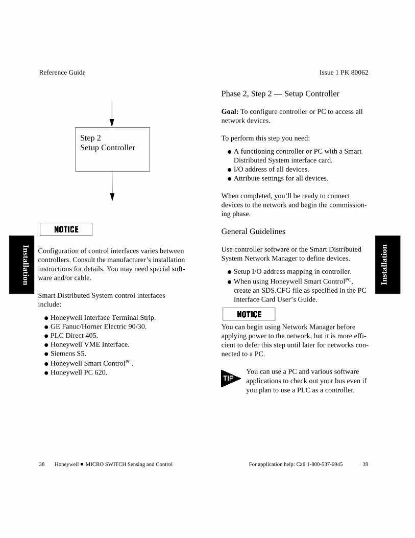
Step 2Setup Controller
Configuration of control interfaces varies between controllers. Consult the manufacturer’s installation instructions for details. You may need special soft-ware and/or cable.
Smart Distributed System control interfaces include:
Honeywell Interface Terminal Strip. GE Fanuc/Horner Electric 90/30. PLC Direct 405. Honeywell VME Interface. Siemens S5. Honeywell Smart ControlPC. Honeywell PC 620.
Issue 1 PK 80062
For application help: Call 1-800-537-6945 39
Inst
alla
tion
Phase 2, Step 2 — Setup Controller
Goal: To configure controller or PC to access all network devices.
To perform this step you need:
A functioning controller or PC with a Smart Distributed System interface card.
I/O address of all devices. Attribute settings for all devices.
When completed, you’ll be ready to connect devices to the network and begin the commission-ing phase.
General Guidelines
Use controller software or the Smart Distributed System Network Manager to define devices.
Setup I/O address mapping in controller. When using Honeywell Smart ControlPC,
create an SDS.CFG file as specified in the PC Interface Card User’s Guide.
You can begin using Network Manager before applying power to the network, but it is more effi-cient to defer this step until later for networks con-nected to a PC.
You can use a PC and various software applications to check out your bus even if you plan to use a PLC as a controller.
Reference Guide
40 Honeywell l MICRO SWITCH Sensing and Control
Installation
Step 1Pre-Power Up Checklist
Phase 3Commission System
Step 2Use Power up Checklist
Step 3Use Pre-Control Program Execu-tion Checklist
Step 1Use Pre-Power up Checklist
Ready for System Integration
3
Step 4Document System
Issue 1 PK 80062
For application help: Call 1-800-537-6945 41
Inst
alla
tion
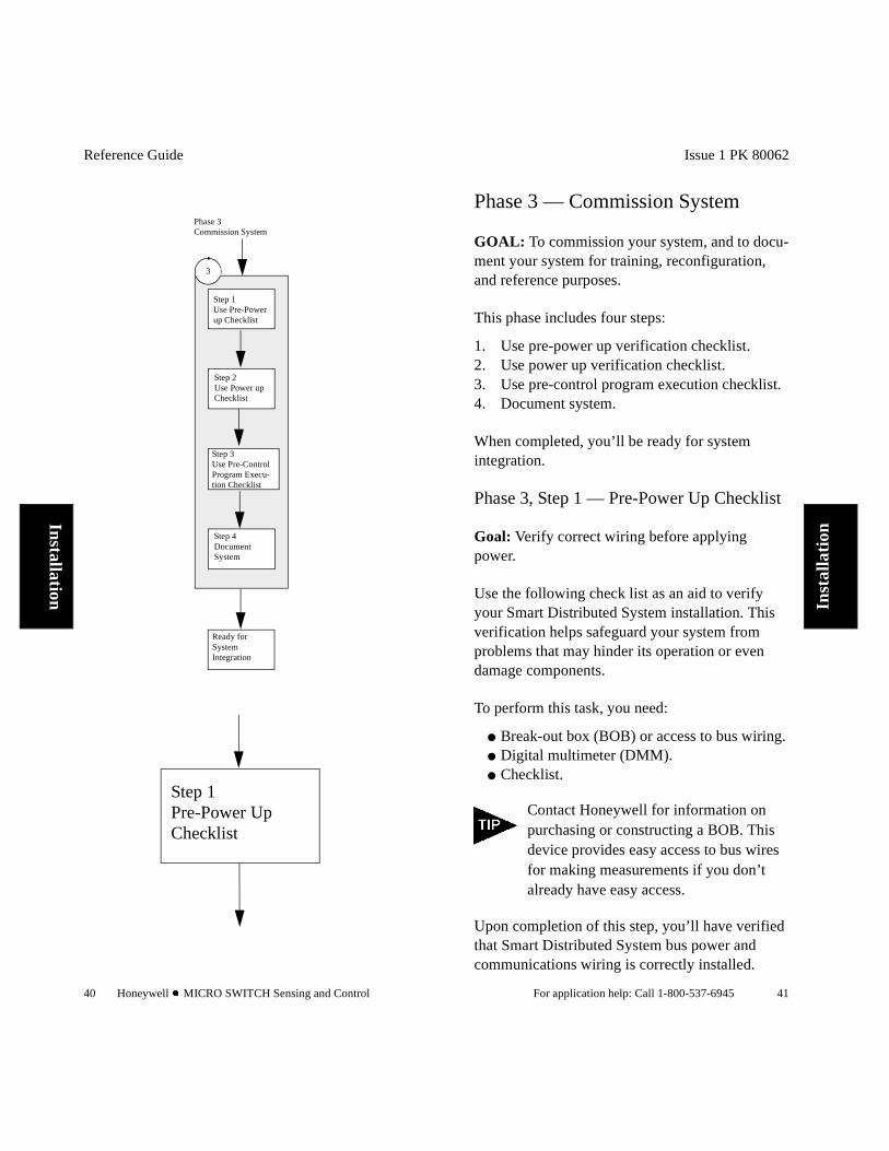
Phase 3 — Commission System
GOAL: To commission your system, and to docu-ment your system for training, reconfiguration, and reference purposes.
This phase includes four steps:
1. Use pre-power up verification checklist.2. Use power up verification checklist.3. Use pre-control program execution checklist.4. Document system.
When completed, you’ll be ready for system integration.
Phase 3, Step 1 — Pre-Power Up Checklist
Goal: Verify correct wiring before applying power.
Use the following check list as an aid to verify your Smart Distributed System installation. This verification helps safeguard your system from problems that may hinder its operation or even damage components.
To perform this task, you need:
Break-out box (BOB) or access to bus wiring. Digital multimeter (DMM). Checklist.
Contact Honeywell for information on purchasing or constructing a BOB. This device provides easy access to bus wires for making measurements if you don’t already have easy access.
Upon completion of this step, you’ll have verified that Smart Distributed System bus power and communications wiring is correctly installed.

Reference Guide
42 Honeywell l MICRO SWITCH Sensing and Control
Installation
Pre-Power Up Checklist
Before Powering You Bus
o Make sure there are no short circuits or reversed wiring in the communication and power lines.
o Use two 120 ohm terminating resistors on the extreme ends of each bus.
o Verify that the resistance across bus positive and negative, while power is off, falls between 50 and 70 ohms.
o Ensure that the bend radius is greater than 8” for mini-sized cables and greater than 3” for micro-sized cables.
o Check the number of loads on the bus (only 64 “smart” devices permitted).
o Hand-tighten all screw-terminal connections and be sure that the green ring lines on all plug-and-play connections are showing.
o Do not install your bus wiring closer than 3 inches to other wiring. Do not place your bus wiring in parallel with power or other system wiring.
o Verify that the:
Shield drain-wire is intact. Shield drain-wire measures less than 1 ohm to
earth-ground. Shield drain-wire is attached at a single point
to control earth-ground start-point. Shield drain-wire is clipped flush with cable at
all devices. Black-white and brown-white pairs remain
twisted and as short as possible.
ý :$51,1*UNEXPECTED SYSTEM OPERATION
Follow all checklist steps completely to aid proper system operation.
Failure to comply with these instructions could result in death or serious injury.
Issue 1 PK 80062
For application help: Call 1-800-537-6945 43
Inst
alla
tion
Phase 3, Step 1 Continued1. Verify that the:
Shield drain-wire measures less than 1 ohm to earth-ground.
Shield drain-wire is attached at a single point to control earth-ground start-point.
Terminating resistors (120 Ohm, 1/2 Watt, 2%) are in place at extreme ends of each bus.
2. For pigtail, bulkhead, or hardwired connec-tions, verify that the: Shield drain-wire is clipped flush where it exits
the cable at devices and control panels unless it is the single earth ground point.
Black-white and brown-white pairs remain twisted and as short as possible.
Pre-Power Up Checklist by the Numbers
Before powering the bus, we recommend that you:
1. Use a Break-out box and a DMM to look for short circuits and reversed wiring in the com-munication and power lines.
2. Measure resistance across bus positive and negative while the power is off. The value should fall between 50 and 70 ohms.
If the resistance is greater than 60Ω, make sure there is a terminating resistor at each end of the bus. If resistance is less than 60Ω, look for and remove extra terminating resistors. Typical culprits are additional PCs added to the network for debugging.
3. Ensure that all cable and tee supports elimi-nate stress on cable connections.
4. Verify that the bend radius is greater than 8" for mini-sized cables and 3" for micro-sized cables.
Reference Guide
44 Honeywell l MICRO SWITCH Sensing and Control
Installation
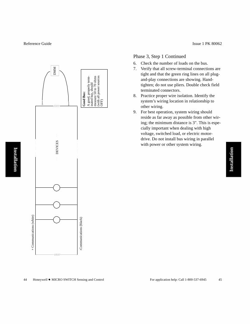
Goo
d B
us:
A g
ood,
pro
perl
y te
rm-
inat
ed b
us, s
houl
dm
easu
re 5
0 to
70
ohm
s(w
ith a
ll po
wer
sou
rces
OFF
)
DM
MD
EV
ICE
S
+ C
omm
unic
atio
ns (
whi
te)
-Com
mun
icat
ions
(bl
ack)
Issue 1 PK 80062
For application help: Call 1-800-537-6945 45
Inst
alla
tion
Phase 3, Step 1 Continued6. Check the number of loads on the bus. 7. Verify that all screw-terminal connections are
tight and that the green ring lines on all plug-and-play connections are showing. Hand-tighten; do not use pliers. Double check field terminated connectors.
8. Practice proper wire isolation. Identify the system’s wiring location in relationship to other wiring.
9. For best operation, system wiring should reside as far away as possible from other wir-ing; the minimum distance is 3". This is espe-cially important when dealing with high voltage, switched load, or electric motor-drive. Do not install bus wiring in parallel with power or other system wiring.
Reference Guide
46 Honeywell l MICRO SWITCH Sensing and Control
Installation
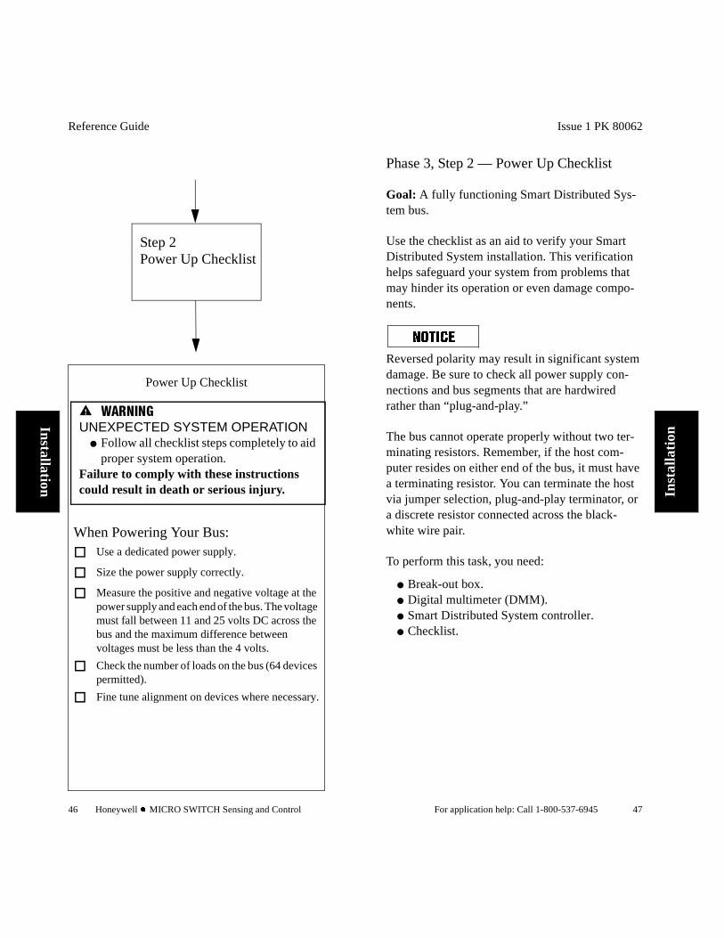
Power Up Checklist
When Powering Your Bus:
o Use a dedicated power supply.
o Size the power supply correctly.
o Measure the positive and negative voltage at the power supply and each end of the bus. The voltage must fall between 11 and 25 volts DC across the bus and the maximum difference between voltages must be less than the 4 volts.
o Check the number of loads on the bus (64 devices permitted).
o Fine tune alignment on devices where necessary.
Step 2Power Up Checklist
ý :$51,1*UNEXPECTED SYSTEM OPERATION
Follow all checklist steps completely to aid proper system operation.
Failure to comply with these instructions could result in death or serious injury.
Issue 1 PK 80062
For application help: Call 1-800-537-6945 47
Inst
alla
tion
Phase 3, Step 2 — Power Up Checklist
Goal: A fully functioning Smart Distributed Sys-tem bus.
Use the checklist as an aid to verify your Smart Distributed System installation. This verification helps safeguard your system from problems that may hinder its operation or even damage compo-nents.
Reversed polarity may result in significant system damage. Be sure to check all power supply con-nections and bus segments that are hardwired rather than “plug-and-play.”
The bus cannot operate properly without two ter-minating resistors. Remember, if the host com-puter resides on either end of the bus, it must have a terminating resistor. You can terminate the host via jumper selection, plug-and-play terminator, or a discrete resistor connected across the black-white wire pair.
To perform this task, you need:
Break-out box. Digital multimeter (DMM). Smart Distributed System controller. Checklist.
Reference Guide
48 Honeywell l MICRO SWITCH Sensing and Control
Installation
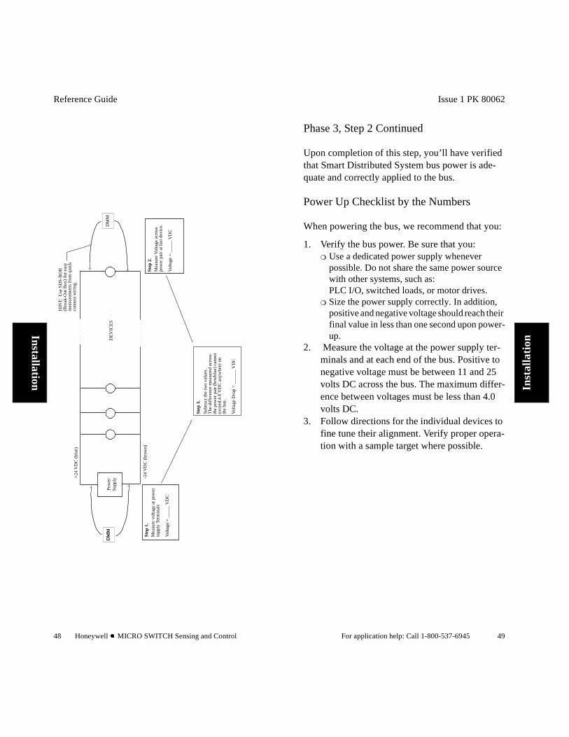
Pow
erS
uppl
y
Mea
sure
vol
tage
at p
ower
supp
ly T
erm
inal
s
Vol
tage
= _
____
VD
C
Step
2.
Mea
sure
Vol
tage
acr
oss
pow
er p
air
at la
st d
evic
e.
Vol
tage
= _
____
VD
C
Step
3.
Step
1.
Subt
ract
the
two
valu
es.
The
dif
fere
nce
mea
sure
d ac
ross
th
e po
wer
pai
r (b
rn/b
lue)
can
not
exce
ed 4
.0 V
DC
any
whe
re o
nth
e bu
s.
Vol
tage
Dro
p =
____
__ V
DC
DM
MD
MM
DM
M
HIN
T:
Use
SD
S-B
OB
(Bre
ak-O
ut B
ox)
for
easy
mea
sure
men
ts f
rom
qui
ckco
nnec
t wir
ing.
DE
VIC
ES
+24
VD
C (
blue
)
-24
VD
C (
brow
n)
Issue 1 PK 80062
For application help: Call 1-800-537-6945 49
Inst
alla
tion
Phase 3, Step 2 Continued
Upon completion of this step, you’ll have verified that Smart Distributed System bus power is ade-quate and correctly applied to the bus.
Power Up Checklist by the Numbers
When powering the bus, we recommend that you:
1. Verify the bus power. Be sure that you: Use a dedicated power supply whenever
possible. Do not share the same power source with other systems, such as: PLC I/O, switched loads, or motor drives.
Size the power supply correctly. In addition, positive and negative voltage should reach their final value in less than one second upon power-up.
2. Measure the voltage at the power supply ter-minals and at each end of the bus. Positive to negative voltage must be between 11 and 25 volts DC across the bus. The maximum differ-ence between voltages must be less than 4.0 volts DC.
3. Follow directions for the individual devices to fine tune their alignment. Verify proper opera-tion with a sample target where possible.
Reference Guide
50 Honeywell l MICRO SWITCH Sensing and Control
Installation
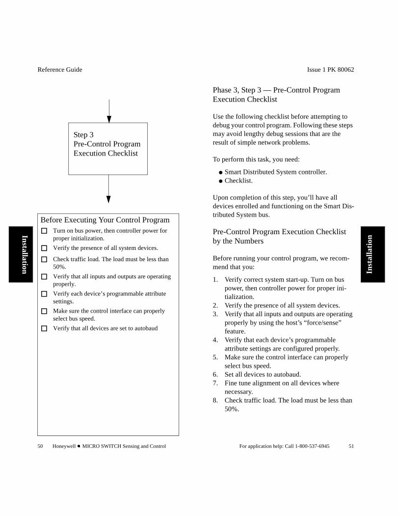
Before Executing Your Control Program
o Turn on bus power, then controller power for proper initialization.
o Verify the presence of all system devices.
o Check traffic load. The load must be less than 50%.
o Verify that all inputs and outputs are operating properly.
o Verify each device’s programmable attribute settings.
o Make sure the control interface can properly select bus speed.
o Verify that all devices are set to autobaud
Step 3Pre-Control Program Execution Checklist
Issue 1 PK 80062
For application help: Call 1-800-537-6945 51
Inst
alla
tion
Phase 3, Step 3 — Pre-Control Program Execution Checklist
Use the following checklist before attempting to debug your control program. Following these steps may avoid lengthy debug sessions that are the result of simple network problems.
To perform this task, you need:
Smart Distributed System controller. Checklist.
Upon completion of this step, you’ll have all devices enrolled and functioning on the Smart Dis-tributed System bus.
Pre-Control Program Execution Checklist by the Numbers
Before running your control program, we recom-mend that you:
1. Verify correct system start-up. Turn on bus power, then controller power for proper ini-tialization.
2. Verify the presence of all system devices. 3. Verify that all inputs and outputs are operating
properly by using the host’s “force/sense” feature.
4. Verify that each device’s programmable attribute settings are configured properly.
5. Make sure the control interface can properly select bus speed.
6. Set all devices to autobaud.7. Fine tune alignment on all devices where
necessary.8. Check traffic load. The load must be less than
50%.

Reference Guide
52 Honeywell l MICRO SWITCH Sensing and Control
Installation
Commissioning Checklist Summary
Use this check list as you install your Smart Dis-tributed System bus.
Before Powering Your Bus: Make sure there are no short circuits or reversed
wiring in the communication and power lines. Use two 120 Ohm,1/2 Watt, 2% terminating
resistors on the extreme ends of each bus. Verify that the resistance across bus positive
and negative, while the power is off, falls between 50 and 70 ohms.
Ensure that the bend radius is greater than 8" for mini-sized cables and greater than 3" for micro-sized cables.
Verify: Bus speed is correct. Host baud rate is set to the appropriate value. Bus length (overall and branch length) is within
guidelines. Devices are correctly addressed.
Check the number of loads on the bus (only 64 “smart” devices permitted).
Hand-tighten all screw-terminal connections and be sure that the green ring lines on all plug-and-play connections are showing.
Do not install your bus wiring closer than 3" to other wiring. Do not place your bus wiring in parallel with power or other system wiring.
Verify that the: Shield drain-wire is intact. Shield drain-wire measures less than 1 ohm to
earth-ground. Shield drain-wire is attached at a single point to
control earth-ground start-point. Shield drain-wire is clipped flush with cable at
devices. Black-white and brown-white pairs remain
twisted and as short as possible.
Issue 1 PK 80062
For application help: Call 1-800-537-6945 53
Inst
alla
tion
Phase 3, Step 4 — Document System
Goal: Fully document system to facilitate system integration and future troubleshooting and system enhancement.
To perform this task, you may need the following:
Handheld activator. Layout with as-installed markups. Control software documentation. Network Manager software for PC-based
applications.
A load of more than 20% on an idle bus may indi-cate incorrectly configured devices.
Attributes which can impact bus load include (but are not limited to):
Normally open/normally closed (NO/NC). On Delay/Off Delay. Batch Count. Motion/Jam. SPDT Mode. Cyclical Timer. Unsolicited/Solicited Mode.
An incorrect Unsolicited/Solicited mode setting results in approximately a six second delay in device reaction time.
Some devices are preset to a fixed baud rate. Activating the autobaud feature on your devices helps ensure that they are set to the correct baud rate at bus initializa-tion.

Reference Guide
54 Honeywell l MICRO SWITCH Sensing and Control
Installation
Upon completion of this step, you’ll be ready to begin system integration.
General Guidelines
Final system documentation should include as-installed:
Layout showing network cabling, tees, and branches.
Device location and power requirements. Device address and attribute settings. Control panel, power supply, and ground
location. Complete collection of device specification
and installation sheets. Design documents for custom enclosures or
mounting. Design documents showing special mounting
considerations.

Issue 1 PK 80062
For application help: Call 1-800-537-6945 55
Tro
uble
shoo
ting
Chapter 3Troubleshooting Guide
Chapter Objectives
This chapter identifies some common problems and provides steps you can take to isolate and cor-rect the situation.
Reference Guide
56 Honeywell l MICRO SWITCH Sensing and Control
Troubleshooting
Network Troubleshooting
The two major causes of I/O network problems are:
Physical wiring problems. Communications errors.
The following symptoms may result:
Bus fails to initialize properly (“Error 40” with PC Control).
“Dead Bus.” Devices fail to respond to force/sense actions. Device operation is erratic, intermittent. Network errors are reported (“Missing Node”,
“Bus-Off”, “Duplicate Node”). Problems are not isolated to specific devices. A large number of errors are reported
simultaneously. System operation is unpredictable, erratic.
To isolate a problem on the network:
Step 1. Visually Inspect Physical Layer
The physical layer includes wiring, cables, tees, connectors, terminators, terminal strips, junction boxes, field-terminated connectors, etc. Look for:
Physical damage, such as smashed or pinched cables.
Loose connections. Intermittent shorts or open circuits (check
FTCs and terminal strips). Excessive stress on cable bends, especially
where connectors join tees. Over-tightened connectors (green line should
just be visible).
Issue 1 PK 80062
For application help: Call 1-800-537-6945 57
Tro
uble
shoo
ting
Tees not properly mounted or subject to vibration or stress.
Excessive flexing or vibration of cable during operation.
Proximity of cable to electrical noise sources, AC power wiring, etc.
Experience has shown that you can find many bus-related problems by careful visual observation of the physical wiring. Be especially suspicious of physical problems if a problem begins immediately following other maintenance work, equipment relocation, or other actions that may have disturbed the wiring.
None of the devices are operating properly.
Step 2 - Make Basic Resistance Measurements
Use a DMM connected to a Smart Distributed Sys-tem Break-out Box (BOB) or where you have direct access to the wires (assume you can use direct wire access anywhere the BOB is mentioned in this document) to measure the following:
1. Remove power to all system components, including the bus, all devices, and controller.
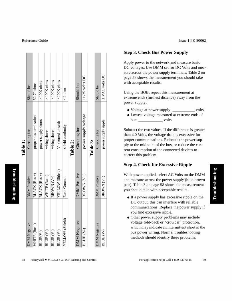
2. Attach the BOB to the network and select “Ohms” range on the DMM. Make the mea-surements suggested in Table 1 on page 58.
You may need to repeat some of these measure-ments at various points along the bus as not all problems (such as open circuits) show up every-where. For example, a loose connection on a screw terminal in a panel may only affect devices that are connected to that panel, even though the rest of the system checks OK.
Reference Guide
58 Honeywell l MICRO SWITCH Sensing and Control
Troubleshooting
Tab
le 1
:
Tab
le 2
:
Tab
le 3
:
DM
M N
egat
ive
DM
M P
osit
ive
Che
ckin
g fo
r:S
houl
d be
:
WH
ITE
(B
us -
)B
LA
CK
(B
us +
)pr
oper
bus
term
inat
ion
50-7
0 oh
ms
BL
UE
(V-)
BL
AC
K (
Bus
+)
pow
er s
uppl
y sh
orts
> 1
000
ohm
s
BL
UE
(V
-)W
HIT
E (
Bus
-)
wir
ing
shor
ts>
100
K o
hms
BL
UE
(V
-)B
RO
WN
(V
+)
wir
ing
shor
ts>
100
K o
hms
BL
UE
(V
-)Y
EL
LO
W (
Shi
eld)
V-
shor
ted
to e
arth
> 1
00K
ohm
s
YE
LL
OW
(S
hiel
d)E
arth
Gro
und
shie
ld c
onti
nuit
y<
1 o
hm
DM
M N
egat
ive
DM
M P
osit
ive
Che
ckin
g fo
r:S
houl
d be
:
BL
UE
(V
-)B
RO
WN
(V
+)
pow
er s
uppl
y vo
ltag
e11
-25
volt
s D
C
DM
M N
egat
ive
DM
M P
osit
ive
Che
ckin
g fo
r:S
houl
d be
:
BL
UE
(V
-)B
RO
WN
(V
+)
pow
er s
uppl
y ri
pple
.1 V
AC
vol
ts D
C
Issue 1 PK 80062
For application help: Call 1-800-537-6945 59
Tro
uble
shoo
ting
Step 3. Check Bus Power Supply
Apply power to the network and measure basic DC voltages. Use DMM set for DC Volts and mea-sure across the power supply terminals. Table 2 on page 58 shows the measurement you should take with acceptable results.
Using the BOB, repeat this measurement at extreme ends (furthest distance) away from the power supply:
Voltage at power supply: ___________ volts. Lowest voltage measured at extreme ends of
bus: ____________ volts.
Subtract the two values. If the difference is greater than 4.0 Volts, the voltage drop is excessive for proper communications. Relocate the power sup-ply to the midpoint of the bus, or reduce the cur-rent consumption of the connected devices to correct this problem.
Step 4. Check for Excessive Ripple
With power applied, select AC Volts on the DMM and measure across the power supply (blue-brown pair). Table 3 on page 58 shows the measurement you should take with acceptable results.
If a power supply has excessive ripple on the DC output, this can interfere with reliable communications. Replace the power supply if you find excessive ripple.
Other power supply problems may include voltage fold-back or “crowbar” protection, which may indicate an intermittent short in the bus power wiring. Normal troubleshooting methods should identify these problems.
Reference Guide
60 Honeywell l MICRO SWITCH Sensing and Control
Troubleshooting
Step 5. Check Auxiliary Power Supply(s)
Some Smart Distributed System devices such as Honeywell “smart” sensors, operate exclusively from the bus power supply. Others, including any device that consumes more than 20-50 ma., require an auxiliary power supply. Problems with auxiliary power supplies may interfere with nor-mal network operation.
Use the DMM to verify proper DC output (and lack of excess ripple) from auxiliary power sup-plies. Consult your system documentation for cor-rect voltage values.
The above checks should isolate most physical wiring problems to the point where you can iden-tify the defect. It is possible that intermittent or hidden, more obscure network communications problems can remain hidden, but perform these simple checks to “eliminate the obvious” before going on.
If devices are powered from an auxiliary power supply, you must cycle BOTH bus power and Auxiliary power for proper bus initialization. You can accomplish this with a dedicated control line, or by slaving one supply to the other. To ensure correct system start up, apply power to the bus and any auxiliary power supply(s), then apply power to the controller. Since devices wait for the host, timing of power supplies is not critical.
Step 6. Check for Network Communica-tions Problems
Communications may be disrupted by intermittent electrical problems — the kind that are always the most difficult to fix! Because Smart Distributed
Issue 1 PK 80062
For application help: Call 1-800-537-6945 61
Tro
uble
shoo
ting
System is a very robust communications network designed to work in factory environments, you need to understand how the protocol operates under adverse conditions, and what can cause it to go wrong.
There are three basic types of communications errors commonly reported:
Bus-off Error — when a device experiences difficulty in communicating and leaves the bus.
Missing Node Error — when the host does not receive a reply from a device when expected.
Duplicate Node Error — when two or more devices have incorrectly been given the same network address.
Smart Distributed System Communications Basics:
Smart Distributed System uses the CAN (control-ler area network) protocol, and sends data over two wires using differential voltages similar to RS 485 in the +/- 2.5 volt range. Due to the high speed involved, a meter or oscilloscope is useless in visualizing what is going on over the network. You need a specialized monitoring tool, along with a basic understanding of how Smart Distributed System works:
Input devices send messages to the host when an event occurs. The host sends messages to output devices when required by the controller. Messages are only sent when necessary, i.e. only one message will be sent to turn an output on, rather than one message every scan.
Recipients send an acknowledgment to every message, except initial autobaud test messages and multicast commands.
Only one device can communicate at any given time. The device’s address determines its
Reference Guide
62 Honeywell l MICRO SWITCH Sensing and Control
Troubleshooting
priority in using the network — lower addresses have priority over higher addresses.
Each message follows strict formatting rules. Any violation of these rules results in an error.
A normally-operating bus will have very few or zero error frames. Smart Distributed System works with occasional error frames, but when an error frame happens, the message must be re-sent.
It’s impossible to say how many error frames are too many. But a change in the number of error frames is a warning that something has changed.
Error frames are invisible to control programs. Telltale signs of excessive error frames include sluggish response, missing devices, or bus-off conditions.
What causes error frames?
Each device listens for its own messages. Any interference will cause the device to generate an error frame. For example, if a noise spike over-rides the expected voltage during a message, it may cause an error. This is why the proper routing and shielding of bus wiring is so important.
Intermittent electrical connections are another cause of error frames. Unlike conventional wiring, even a very brief open circuit in a bus communica-tions wire will disrupt the message in process and cause an error frame. On a positive note, this means that the presence of error frames is an indi-cation that a hard-to-find electrical intermittent problem is present!
What happens to a device when an error frame occurs?
Because each device listens for its own messages,
Issue 1 PK 80062
For application help: Call 1-800-537-6945 63
Tro
uble
shoo
ting
it knows if it may have been the cause of the error. The designers of CAN built features into the sys-tem to quickly remove any malfunctioning devices from the network, and this is probably what is hap-pening if devices seem to disappear or drop off the bus.
Here’s what happens inside a device: When a mes-sage is sent, an internal counter advances, and if no errors occur, the counter decrements back to zero. But if an error occurs, the counter is advanced, and if problems continue, the counter eventually reaches a value of 255 — at which point the device goes bus-off and stops trying to communicate. Although all devices see the error frame, only the device that is sending at the time removes itself from the network.
When a device goes bus-off, it seldom means the device is bad, but rather that there is some interfer-ence when it is trying to send messages. It may be that some outside interference was persistent enough to interfere with successive messages from the device, forcing it to go bus-off. Another expla-nation is that electrical noise may be occurring at random times, creating bus-off conditions in ran-dom devices. Of course, it is also possible that there is a defect in a device, and by going bus-off, it allows the rest of the network to communicate as designed.
When a bus-off condition occurs, the device first sends a diagnostic message to the host to signal that it is leaving the network. Then the internal microprocessor in the device is reset and tries to re-join the network. If a problem is really persis-tent, it may do so, only to be forced off the bus again. This can create the symptom of erratic oper-ation of a system which works while the device is present, and fails to work when it is off-bus.

Reference Guide
64 Honeywell l MICRO SWITCH Sensing and Control
Troubleshooting
Remember: Bus-off is an indication that the device had difficulty communicating.
What causes Missing Node errors?
When a device is reported as missing, this means the host was unable to communicate with it as expected.
Each host polls each device on the network at a pre-defined interval to make sure all devices are present. For the Honeywell PC Interface Card, this rate is set at 2.5 seconds. If no communication has occurred with a device, the Honeywell PC Inter-face Card sends a heartbeat message approxi-mately every 2.5 seconds, and if the device fails to respond, it reports a missing node error.
Missing node generally is a clear signal that the device is not electrically present on the bus. How-ever, under extremely heavy bus traffic conditions, it’s possible for a missing node error to occur because other devices (with higher priority) pre-vent the response from being sent. While not com-mon, missing node is sometimes an indication of excessively-high bus traffic, which may be the result of a device with cyclical timer (Attribute 10) enabled, a device that is chattering, or a program-ming error in the control software which is gener-ating excessive traffic. It will be difficult to detect this condition without some type of bus analyzer.
How to diagnose communications prob-lems:1. Look for signs of communications errors.
Each controller is different, for example, in the Honeywell PC Interface Card, the bus-off error is bit 0 of byte 2 in the Device Diagnos-
Issue 1 PK 80062
For application help: Call 1-800-537-6945 65
Tro
uble
shoo
ting
tic Register. By examining the diagnostic reg-ister, you can tell which device is experiencing the error. Examine the device and its bus con-nections carefully. You may wish to try substi-tuting a new device (properly addressed) to determine if the problem is in the network or device. Other tools, such as SDSTOOLS and the Honeywell Network Manager let you see errors on the network.
2. Examine the environment for possible causes of communications errors:
EMI or electrical noise from generators, motors, welders, high voltage arcing, battery chargers, hand-held radios, etc. Check the list of case histories on page 75 for suggestions.
Electrostatic discharge is a problem unique to some conveyor applications. One technique is to run the conveyor with lights out so you can more readily see arcing ESD. Grounding may be necessary to eliminate ESD.
Do problems happen at certain times of day when specific equipment may be in use?
Try keeping a log of all communications problems — a trend may emerge over time.
3. Look for signs of excessive bus traffic. The Handheld Activator provides a function for measuring bus activity — typical values should be under 50%. Examine the control software and device attributes for potential causes of excessive bus traffic.
Attribute 6 should be 0 for unsolicited (event-driven) operation.
Some photoelectric sensors can false-trigger on florescent lights, light-curtains, and other sensors, creating excessive traffic.
Avoid traffic-generating control software techniques such as reading or clearing diagnostics in every scan.
Reference Guide
66 Honeywell l MICRO SWITCH Sensing and Control
Troubleshooting
Try stopping the control program (but leave the bus running) to see if this reduces bus traffic.
Try removing suspect devices (see also What is Divide and Conquer page 67).
4. Make sure there are no duplicate addresses. If two devices exist with the same address, they will both respond at the same time result-ing in error frames. Because both devices have the same priority, this will continue until both devices go bus-off. This process will continue until you resolve the duplicate address prob-lem. (To guard against this, Honeywell’s PC control software checks for duplicate node addresses at start-up.) You will have to re-check addresses or remove devices from the bus to determine if duplicate addresses are present.
Step 7. Using Advanced Troubleshooting Techniques
If problems continue, at this point you have three options:
1. Call Honeywell’s Customer Response Center at 800-537-6945 in the U.S., (815) 235-6847 elsewhere. An application engineer may be able to provide further assistance or arrange for an appropriate service response.
2. Continue troubleshooting on your own with-out specialized tools.
3. Continue troubleshooting on your own, but with special bus test equipment.
Option 1:
Unless you are experienced in troubleshooting CAN-based networks, arranging for Honeywell service may be the best option, especially if time is of the essence.
Issue 1 PK 80062
For application help: Call 1-800-537-6945 67
Tro
uble
shoo
ting
Option 2 or 3:
If you are willing and able to invest more time and effort, you can isolate many problems without spe-cial test equipment or outside help. But the most efficient method involves using special purpose tools that will help pinpoint network communica-tions problems. In either case, use a divide and conquer approach to isolate the problem.
What is divide and conquer? Because all devices are connected in parallel, it is necessary to discon-nect some devices to isolate the problem to a phys-ical location. Follow these rules during this process:
1. Whenever a bus is broken into segments, install a terminator on the segment that is still operational.
2. Depending on the power supply location, you may need to provide power to the bus during troubleshooting work.
3. Remember to put everything back when fin-ished!
ý :$51,1*PERSONAL INJURY
Be sure that troubleshooting activities, which will render parts of the bus inoperative, do not result in unsafe conditions.
Failure to comply with these instructions could result in death or serious injury.

Reference Guide
68 Honeywell l MICRO SWITCH Sensing and Control
Troubleshooting
Divide and conquer without specialized tools:
1. Remove all power from the network and con-troller.
2. Break the bus at the midpoint, and install a ter-minator on the end that is connected to the controller. (If the power supply has been dis-connected, you must supply power in some other way).
3. Re-start the controller and observe the results. If the problem is gone, then it must be some-where in the half that is now disconnected. If the problem persists, it must be in the half that is still connected. Either way, you’ve just eliminated half of the bus wiring as the possi-ble source of the problem.
4. Remove power again, and restore the original connection.
5. Move halfway from the midpoint (i.e. on the results of step #3) and again break the bus and attach the terminator.
6. Again re-start the controller and observe the results.
7. Continue, successively moving halfway closer each step until the problem is isolated. When the direction of the problem reverses, you know exactly where the problem is located.
8. Continue with normal troubleshooting if needed, or fix the problem by replacing the defective component or device.
This process is the fastest method to isolate a prob-lem. It is also the least disruptive to the system. The biggest weakness is the need to continuously re-start the control system to observe the effect of each change. Another shortcoming of this approach is that it may take a long time to see the effect of each step, especially if the problem is intermittent in nature.
Issue 1 PK 80062
For application help: Call 1-800-537-6945 69
Tro
uble
shoo
ting
Divide and conquer — with specialized tools: The process is the same, except specialized equip-ment makes it easy to see the effect of each step in the troubleshooting process.
In addition to error frames, most communications problems, including duplicate addresses and elec-trical interference causing bus-off errors, are an indication that there is a problem in the physical wiring. Thus, a tool that can detect error frames greatly simplifies the troubleshooting process.
What specialized tools are available?
The number of tools capable of detecting error frames is relatively small, but includes:
Honeywell CAN Error Monitor. This is a small, bus-powered portable device which provides an indication of error frames.
Honeywell SDSMON. This is a PC-based tool, which is meant to run on a laptop computer having a PCMCIA card slot to accept the interface adapter. Software provides for data capture and logging as well as error detection.
Vector CANalyzer. This is a PC-based high-end CAN network analyzer, which has been customized to display messages. It offers very extensive features and is meant for use by experts.
It is important to note that the Hand-Held Activa-tor, Honeywell PC Interface Card, and all other PC/PLC controller interfaces today do not have the ability to detect error frames.
The best way to select the proper tool for your needs is to consult with an application engineer in the Honeywell Customer Response Center.

Reference Guide
70 Honeywell l MICRO SWITCH Sensing and Control
Troubleshooting
How are specialized tools used?
Error Monitor: You can attach the portable Error Monitor to a
network anywhere that is convenient (just don’t exceed topology limits!), so you can easily see the effect of changes.
If a hidden problem exists — such as a loose connection in a plug-and-play tee — you may need to shake, wiggle, or bend a connector while observing the effect on the Error Monitor.
The audible alarm of the Error Monitor may be coupled over a radio link.
PC-based Tools: You can configure the PC-based tools to log
data for off-line analysis. These tools time-stamp each event in the PC so
you can see trends. You can leave PC-based tools connected for
long-term, unattended monitoring. The PC provides more data, including number
and type of various messages, and timing of messages. You can set it to monitor all, or specific groups of addresses.
Specialized tools will speed the troubleshooting process by identifying error frames that occur as a result of communications problems on the net-work. It’s important to remember that error frames are different than other errors, such as a device error (low gain on a photoeye, for example), or a network error (such as Missing Node). Error frames are an indication of problems at the CAN communications level, and are most often the result of intermittent electrical connections or external electrical noise that is entering the system and interfering with network communications. Review the Installation Guide section on ground-ing, shielding, and proper wiring practices.
Issue 1 PK 80062
For application help: Call 1-800-537-6945 71
Tro
uble
shoo
ting
Step 8. Network Management Problems
As an evolving network and standard, some aspects of network behavior are not completely documented, and are implemented differently by different manufacturers.
One example of this is how the host manages a network during start-up or after a power failure. For purpose of illustration, the next section describes how the widely-used Honeywell PC Interface Card behaves.
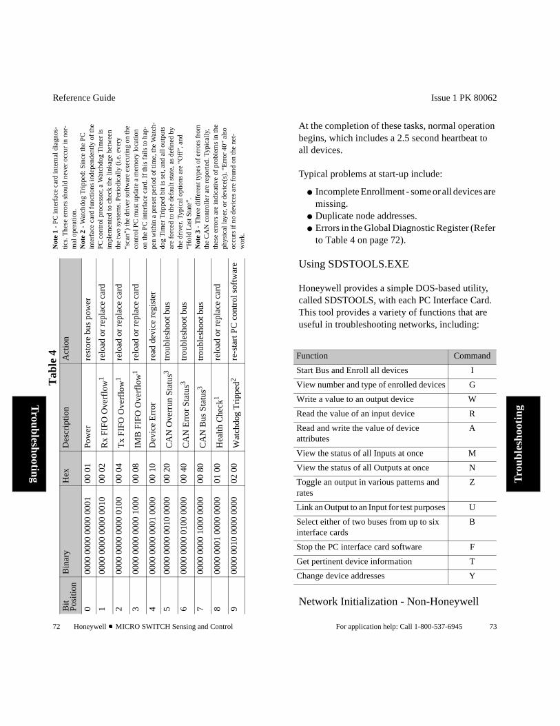
Network Initialization — Honeywell PC Interface Card
When the network is powered-on, all devices are inhibited from sending messages, awaiting instruc-tions from the host.
The Honeywell PC Interface Card is a self-con-tained co-processor which supports two buses. The software which runs the card is stored on the PC hard drive and downloaded by a routine called SDSBEGIN. (Consult the PC Interface Users Guide for complete details). Honeywell recom-mends creation of a configuration file, which will determine that all devices are present and properly configured at start-up, and helps automatic detec-tion of certain types of network errors.
From a network viewpoint, the PC interface card performs two important functions at start-up:
Autobaud - the host allows each device to select the proper network data communications rate.
Enrollment - the host determines the type of device at each address and prepares to communicate with each device.
Reference Guide
72 Honeywell l MICRO SWITCH Sensing and Control
Troubleshooting
Tab
le 4
Bit
Pos
itio
nB
inar
yH
exD
escr
ipti
onA
ctio
n
000
00 0
000
0000
000
100
01
Pow
erre
stor
e bu
s po
wer
100
00 0
000
0000
001
000
02
Rx
FIF
O O
verf
low
1re
load
or
repl
ace
card
200
00 0
000
0000
010
000
04
Tx
FIF
O O
verf
low
1re
load
or
repl
ace
card
300
00 0
000
0000
100
000
08
IMB
FIF
O O
verf
low
1re
load
or
repl
ace
card
400
00 0
000
0001
000
000
10
Dev
ice
Err
orre
ad d
evic
e re
gist
er
500
00 0
000
0010
000
000
20
CA
N O
verr
un S
tatu
s3tr
oubl
esho
ot b
us
600
00 0
000
0100
000
000
40
CA
N E
rror
Sta
tus3
trou
bles
hoot
bus
700
00 0
000
1000
000
000
80
CA
N B
us S
tatu
s3tr
oubl
esho
ot b
us
800
00 0
001
0000
000
001
00
Hea
lth
Che
ck1
relo
ad o
r re
plac
e ca
rd
900
00 0
010
0000
000
002
00
Wat
chdo
g T
ripp
ed2
re-s
tart
PC
con
trol
sof
twar
e
Not
e 1
- P
C in
terf
ace
card
inte
rnal
dia
gnos
-
tics.
The
se e
rror
s sh
ould
nev
er o
ccur
in n
or-
mal
ope
ratio
n.N
ote
2 -
Wat
chdo
g T
ripp
ed: S
ince
the
PC
in
terf
ace
card
fun
ctio
ns in
depe
nden
tly o
f th
e PC
con
trol
pro
cess
or, a
Wat
chdo
g T
imer
is
impl
emen
ted
to c
heck
the
linka
ge b
etw
een
the
two
syst
ems.
Per
iodi
cally
(i.e
. eve
ry
“sca
n”)
the
dri
ver
soft
war
e ex
ecu
ting
on
the
co
ntro
l PC
mu
st u
pda
te a
mem
ory
loca
tion
on
the
PC
inte
rfa
ce c
ard
. If
this
fai
ls to
hap
-pe
n w
ithin
a p
rese
t per
iod
of t
ime,
the
Wat
ch-
dog
Tim
er T
rip
ped
bit
is s
et, a
nd a
ll o
utp
uts
ar
e fo
rced
to
the
defa
ult
stat
e, a
s de
fined
by
the
dri
ver.
Typ
ical
op
tions
are
“O
ff”, a
nd
“Hol
d L
ast
Sta
te”.
Not
e 3
- T
hre
e d
iffe
ren
t typ
es o
f er
rors
fro
m
the
CA
N c
on
tro
ller
are
rep
ort
ed.
Typ
ical
ly,
thes
e er
rors
are
indi
cativ
e o
f p
robl
ems
in th
e ph
ysic
al l
ayer
, o
r d
evic
e(s
). “
Err
or
40
” al
so
occu
rs if
no
dev
ices
are
fo
und
on
the
net
-w
ork
.
Issue 1 PK 80062
For application help: Call 1-800-537-6945 73
Tro
uble
shoo
ting
At the completion of these tasks, normal operation begins, which includes a 2.5 second heartbeat to all devices.
Typical problems at start-up include:
Incomplete Enrollment - some or all devices are missing.
Duplicate node addresses. Errors in the Global Diagnostic Register (Refer
to Table 4 on page 72).
Using SDSTOOLS.EXE
Honeywell provides a simple DOS-based utility, called SDSTOOLS, with each PC Interface Card. This tool provides a variety of functions that are useful in troubleshooting networks, including:
Network Initialization - Non-Honeywell
Function Command
Start Bus and Enroll all devices I
View number and type of enrolled devices G
Write a value to an output device W
Read the value of an input device R
Read and write the value of device attributes
A
View the status of all Inputs at once M
View the status of all Outputs at once N
Toggle an output in various patterns and rates
Z
Link an Output to an Input for test purposes U
Select either of two buses from up to six interface cards
B
Stop the PC interface card software F
Get pertinent device information T
Change device addresses Y

Reference Guide
74 Honeywell l MICRO SWITCH Sensing and Control
Troubleshooting
Controllers
Different PC and PLC controllers and the ITS all have various means of initialization and start-up of the bus. All must accomplish Autobaud — although some may look to a configuration file rather than poll the network to enroll devices. Refer to manufacturers data sheets and supporting software for details.
Each controller and programming software pack-age provides basic capabilities to view, force, and sense I/O, and this should provide the basic tools for network troubleshooting.
Problems with the Host:
The Host is subject to hardware failure, like any other electronic assembly. For the Honeywell PC interface card, “Error 100” indicates a major hard-ware fault and the card must be replaced. “Error 40” will occur if the CAN interface circuitry on the card is defective, preventing the Host from communicating with the rest of the network. “Error 80” and “Error 20” are indications of Error Frames or other communications problems at the Host. Use the Divide and Conquer method (see page 67).
Problems with Power Sequencing:
When power is applied, all devices begin looking for a Host, and after initialization, both Host and Devices transition into normal operating mode. Under some conditions, such as momentary power disruptions, electrical storms, etc., the Host and Devices may be in different operating modes. Devices should recover properly, but if problems persist, it may be necessary to cycle power to the network. It should not be necessary to cycle power
Issue 1 PK 80062
For application help: Call 1-800-537-6945 75
Tro
uble
shoo
ting
or re-boot the Host.
Since Devices will wait for the Host, the timing of power supplies is not critical.
Case Histories
This is a list of some causes of problems that occurred in Smart Distributed Systems bus imple-mentations:
Terminator with open resistor. Break in shield to a device, allowing noise to
enter. Tees where female contacts had been
deformed, creating intermittent connection. Excessive power supply ripple and noise from
switching power supply. Static discharge from conveyor rollers in
epoxy-paint insulated frame. Be aware of Attribute-6 Solicited/Unsolicited
mode. A 2.5 second delay in response time from devices results when Attribute-6 is set to OFF (solicited mode).
Unexpected operation from devices with “smart” attributes inadvertently enabled.
“Chattering” photoelectric sensors from florescent lights.
Excessive bus traffic caused by reading/clearing diagnostics in every scan.
Errors during Autobaud caused by non-conforming devices.
Excessive Error Frames due to vibration of loose connections.
Ground loops caused by multiple-point grounding of the shield wire.
Noise causing Error Frames due to proximity of Smart Distributed System cables to 440 VAC.

Reference Guide
76 Honeywell l MICRO SWITCH Sensing and Control
Troubleshooting
Erratic operation of network caused by connecting V- (blue) to earth ground.
Excessive Error Frames due to use of unshielded non-approved cable in motor panels.
Shield not connected to earth ground. Damage to devices caused by reversing polarity
of 24 volt power supply. No output from Output device due to incorrect
configuration of Mask register. No bus operation because Bus + and - leads
were reversed in a panel. Excessive voltage drop under worst-case
conditions disrupted communications. Broken internal connection in device. Erratic operation caused by connecting
diagnostic tool without disabling terminator. Damage to devices caused by “Hot Swapping”
- breaking the bus trunk with power on. Bus power short caused by defective screw-on
cap on diagnostic tee. Excessive Error Frames after fork-lift ran over
bus cable. Use of wire-nuts or other poor connecting
methods. Damage to cables by use as foot-rest, hand-
hold, etc. Failure of connector as a result of using pliers
to over-tighten. Communications problems caused by use of
unshielded bulkhead cables inside power cabinets.
Errors when using RS-232 type cable for the Smart Distributed System bus.
Inability to cycle power to auxiliary power supplies.
Incorrect Attribute Settings.

Issue 1 PK 80062
For application help: Call 1-800-537-6945 77
Ref
eren
ce
Chapter 4Reference
Chapter Objectives
This chapter:
Defines commonly used terms that you may encounter in this and other Smart Distributed System documentation.
Defines Smart Distributed System physical specifications.
Summarizes correct design methodology to assure successful implementation of a Smart Distributed System.
Commonly Used Terms
This term: Is defined as:
Attribute A device value that you can read and/or write.
Branch The physical cable that connects a device to the trunk, sometimes known as “drop cable.”
Bus The logical medium within the trunk and branches, connecting network devices and the controller, over which communication takes place.
CAN(Controller Area Network)
A serial data bus for real-time applications. The device network protocol used by Smart Distributed System
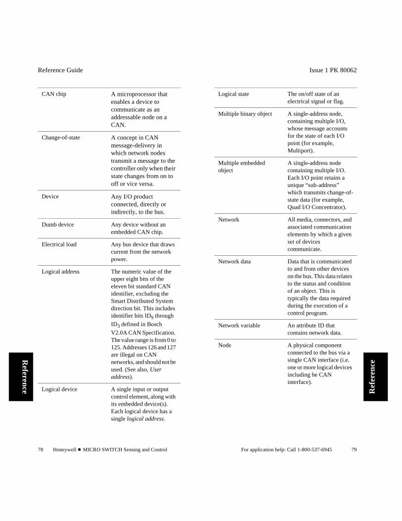
Reference Guide
78 Honeywell l MICRO SWITCH Sensing and Control
Reference
CAN chip A microprocessor that enables a device to communicate as an addressable node on a CAN.
Change-of-state A concept in CAN message-delivery in which network nodes transmit a message to the controller only when their state changes from on to off or vice versa.
Device Any I/O product connected, directly or indirectly, to the bus.
Dumb device Any device without an embedded CAN chip.
Electrical load Any bus device that draws current from the network power.
Logical address The numeric value of the upper eight bits of the eleven bit standard CAN identifier, excluding the Smart Distributed System direction bit. This includes identifier bits ID9 through
ID3 defined in Bosch
V2.0A CAN Specification. The value range is from 0 to 125. Addresses 126 and 127 are illegal on CAN networks, and should not be used. (See also, User address).
Logical device A single input or output control element, along with its embedded device(s). Each logical device has a single logical address.
Issue 1 PK 80062
For application help: Call 1-800-537-6945 79
Ref
eren
ce
Logical state The on/off state of an electrical signal or flag.
Multiple binary object A single-address node, containing multiple I/O, whose message accounts for the state of each I/O point (for example, Multiport).
Multiple embedded object
A single-address node containing multiple I/O. Each I/O point retains a unique “sub-address” which transmits change-of-state data (for example, Quad I/O Concentrator).
Network All media, connectors, and associated communication elements by which a given set of devices communicate.
Network data Data that is communicated to and from other devices on the bus. This data relates to the status and condition of an object. This is typically the data required during the execution of a control program.
Network variable An attribute ID that contains network data.
Node A physical component connected to the bus via a single CAN interface (i.e. one or more logical devices including he CAN interface).
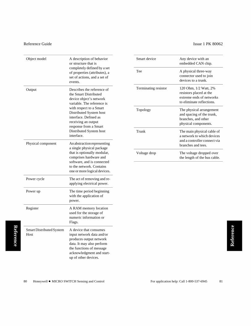
Reference Guide
80 Honeywell l MICRO SWITCH Sensing and Control
Reference
Object model A description of behavior or structure that is completely defined by a set of properties (attributes), a set of actions, and a set of events.
Output Describes the reference of the Smart Distributed device object’s network variable. The reference is with respect to a Smart Distributed System host interface. Defined as receiving an output response from a Smart Distributed System host interface.
Physical component An abstraction representing a single physical package that is optionally modular, comprises hardware and software, and is connected to the network. Contains one or more logical devices.
Power cycle The act of removing and re-applying electrical power.
Power up The time period beginning with the application of power.
Register A RAM memory location used for the storage of numeric information or Flags.
Smart Distributed System Host
A device that consumes input network data and/or produces output network data. It may also perform the functions of message acknowledgment and start-up of other devices.
Issue 1 PK 80062
For application help: Call 1-800-537-6945 81
Ref
eren
ce
Smart device Any device with an embedded CAN chip.
Tee A physical three-way connector used to join devices to a trunk.
Terminating resistor 120 Ohm, 1/2 Watt, 2% resistors placed at the extreme ends of networks to eliminate reflections.
Topology The physical arrangement and spacing of the trunk, branches, and other physical components.
Trunk The main physical cable of a network to which devices and a controller connect via branches and tees.
Voltage drop The voltage dropped over the length of the bus cable.

Reference Guide
82 Honeywell l MICRO SWITCH Sensing and Control
Reference
Topology
Topology is the physical arrangement and spacing of the trunk, branches and nodes. A standard topology is a single trunk with short branches. For information on minimum node separation, see the table on page 84.
Factors affecting bus length and physical layout include:
Voltage drop on the power pair of the bus cable. See page 59 for additional information.
Resistance of conductors and connectors. Current required by each node.
The table on page 84 gives maximum system trunk lengths for various data rates, independent of bus voltage drop.
Issue 1 PK 80062
For application help: Call 1-800-537-6945 83
Ref
eren
ce
Cables
The two cable categories (standard quick connect cables and conventional point-to-point wiring cables) relate to the two general connection schemes used to implement a system.
Standard (quick connect) Cables: 4-wire, shielded cable with 5-pin mini
connectors. 4-wire, shielded cable with 4-pin micro
connectors. 4-wire, shielded cable with 4-pin micro and
5-pin mini connector combinations. 4-wire, shielded cable with 4-pin micro and
5-pin mini connector pigtails. Tee connectors for bus cable. Terminators that are placed at the ends of the
bus cable. Others not listed.
These cables consist of two twisted shielded pair cables within a single sheath. One twisted pair pro-vides power to devices, the other handles device communications.
Conventional Point-to-Point Wiring
Specifications for and diagrams showing these connectors and cables begin on page 89.
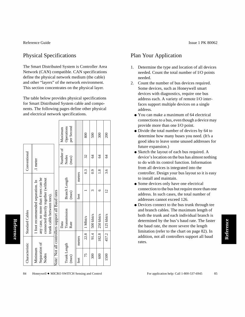
Reference Guide
84 Honeywell l MICRO SWITCH Sensing and Control
Reference
Physical Specifications
The Smart Distributed System is Controller Area Network (CAN) compatible. CAN specifications define the physical network medium (the cable) and other “layers” of the network environment. This section concentrates on the physical layer.
The table below provides physical specifications for Smart Distributed System cable and compo-nents. The following pages define other physical and electrical network specifications.
Cha
ract
eris
ticSt
anda
rd C
able
sC
onve
ntio
nal
Min
imum
Se
para
tion
of
Nod
es
1 fo
ot r
ecom
men
ded
sepa
ratio
n. I
n an
y ca
se, n
o m
ore
than
4 te
es c
an b
e co
nnec
ted
dire
ctly
toge
ther
(w
itho
ut
trun
k ca
ble
betw
een
tees
).
.1 m
eter
Tru
nk L
engt
h(m
ax)
Dat
a T
rans
mis
sion
R
ate
Bra
nch
Len
gth
(max
)
Num
ber
of
Nod
es
(max
)
Max
imum
O
pera
tions
pe
r S
econ
d
feet
met
ers
feet
met
ers
7522
.81
Mbi
t/s1
0.3
3280
0
300
91.4
500
kbit
/s3
0.9
6450
0
600
182.
825
0 kb
it/s
61.
864
300
1500
457.
212
5 kb
it/s
123.
664
200
Not
e: N
ot a
ll c
ontr
olle
rs s
uppo
rt a
ll B
aud
rate
s
Issue 1 PK 80062
For application help: Call 1-800-537-6945 85
Ref
eren
ce
Plan Your Application
1. Determine the type and location of all devices needed. Count the total number of I/O points needed.
2. Count the number of bus devices required. Some devices, such as Honeywell smart devices with diagnostics, require one bus address each. A variety of remote I/O inter-faces support multiple devices on a single address.
You can make a maximum of 64 electrical connections to a bus, even though a device may provide more than one I/O point.
Divide the total number of devices by 64 to determine how many buses you need. (It’s a good idea to leave some unused addresses for future expansion.)
Sketch the layout of each bus required. A device’s location on the bus has almost nothing to do with its control function. Information from all devices is integrated into the controller. Design your bus layout so it is easy to install and maintain.
Some devices only have one electrical connection to the bus but require more than one address. In such cases, the total number of addresses cannot exceed 126.
Devices connect to the bus trunk through tee and branch cables. The maximum length of both the trunk and each individual branch is determined by the bus’s baud rate. The faster the baud rate, the more severe the length limitation (refer to the chart on page 82). In addition, not all controllers support all baud rates.

Reference Guide
86 Honeywell l MICRO SWITCH Sensing and Control
Reference
Issue 1 PK 80062
For application help: Call 1-800-537-6945 87
Ref
eren
ce
Select 125K baud if at all possible. This gives you the greatest flexibility, cable length, and controller selection. (If you need higher baud rates, consult an appli-cation engineer before proceeding.)
3. Once you have a preliminary bus layout, the make sure it meets the following topology rules:
No more than 64 electrical bus connections. No more than 4 tees connected directly
together. Total trunk length less than the maximum
shown on page 84. No branch cable longer than maximum shown
on page 84. Less than 2.0 volts through the V- wire to any
device.
In addition, make sure selected devices do not cre-ate an excessive voltage drop along the bus. A complete analysis requires extensive Ohm’s Law calculations. A simple Excel spreadsheet program (Bus Builder), available from Honeywell, can assist with this calculation.
Place the power supply near the midpoint of the electrical load to minimize voltage drop across the bus. The maximum volt-age drop, as referenced to the power sup-ply terminals, is 2.0 volts in either V- wire, or 4.0 volts from V- to V+.
4. For each bus, prepare an installation drawing that shows:
Location and type of each device. Length and routing of each trunk cable section. Length and routing of each branch cable. Bus power supply location and wiring. Controller wiring. Termination resistor locations (see page 25).

Reference Guide
88 Honeywell l MICRO SWITCH Sensing and Control
Reference
Wire and Cable Alternatives
A variety of cable and wiring schemes can meet your requirements. For example, you can use bulk cable and field-terminated cables for long runs, and bulkhead cables to simplify connections between the bus and control panels. You could purchase new communications cable only, and run the bus power over conventional wiring. New cable options continue to evolve. Contact Honeywell for the latest information.
Topology Alternatives
Some new wiring systems reduce installation time and cost at the expense of reducing overall bus trunk length. Also, CAN-level repeaters and bridges extend cable lengths past the limits by cre-ating star topologies. Contact a Honeywell appli-cation engineer if you feel these alternatives might suit your application.
Plug-and-Play Cabling
Quick connection, ease of installation, and reliable operation make plug-and-play cables a good choice for most applications. While there are a number of suppliers of similar cables, these cables and connectors are not built to a common standard and may not be fully interchangeable. Consult the following pages for available Honeywell cables and wiring accessories.
Issue 1 PK 80062
For application help: Call 1-800-537-6945 89
Ref
eren
ce
Connector PIN Assignments
Cable Catalog Listings
The first letter after the SDS- refers to construction material: A for Regular-Duty, B for Harsh-Duty. The second letter refers to the female end, the third letter to the male end.
Connector Letter Assignment
A - Straight end mini connector.B - Straight end micro connector.C - Pigtail (no connector).D - Right angle mini connector.E - Right angle micro connector.
The last three digits of the part number refer to the cable length (for example, 003 is 3 feet).
5-pin Connector
4-pin Connector
Wire Color
Bus Function
1 — — Cable Shielding
2 1 Brown Power + V
3 2 Blue Power - V
4 3 BlackBus Commu-nications (+)
5 4 WhiteBus Commu-nications (–)

Reference Guide
90 Honeywell l MICRO SWITCH Sensing and Control
Reference
Trunk Cables
If a device has a mini connector, use a trunk cable.
STRAIGHT FEMALE MINI TO STRAIGHT MALE MINI CONNECTOR CABLE
RIGHT-ANGLE FEMALE MINI TO STRAIGHT MALE MINI CONNECTOR TRUNK CABLE
Catalog Listing DescriptionRegular Harsh-DutySDS-AAA-001 SDS-BAA-001 1 ft. (0,3 m)
SDS-AAA-002 SDS-BAA-002 2 ft (0,61 m)
SDS-AAA-003 SDS-BAA-003 3 ft. (0,91 m)
SDS-AAA-006 SDS-BAA-006 6 ft. (1,83 m)
SDS-AAA-010 SDS-BAA-010 10 ft. (3,05 m)
SDS-AAA-012 SDS-BAA-012 12 ft. (3,66 m)
SDS-AAA-025 SDS-BAA-025 25 ft. (7,62 m)
SDS-AAA-050 SDS-BAA-050 50 ft. (15,25 m)
SDS-AAA-080 SDS-BAA-080 80 ft. (24,38 m)
Catalog Listing DescriptionRegular-Duty Harsh-DutySDS-ADA-001 SDS-BDA-001 1 ft. (0,3 m)
SDS-ADA-003 SDS-BDA-003 3 ft. (0,91 m)
SDS-ADA-006 SDS-BDA-006 6 ft. (1,83 m)
SDS-ADA-010 SDS-BDA-010 10 ft. (3,05 m)
SDS-ADA-012 SDS-BDA-012 12 ft. (3,66 m)
SDS-ADA-025 SDS-BDA-025 25 ft. (7,62 m)
SDS-ADA-050 SDS-BDA-050 50 ft. (15,25 m)
Issue 1 PK 80062
For application help: Call 1-800-537-6945 91
Ref
eren
ce
Branch Cables
Use branch cables between the tee or junction box and device.
STRAIGHT FEMALE MICRO TO STRAIGHT MALE MINI CONNECTOR CABLE
STRAIGHT FEMALE MINI CONNECTOR TO PIGTAIL BRANCH CABLE
Catalog Listing DescriptionRegular Duty Harsh-DutySDS-ABA-001 SDS-BBA-001 1 ft. (0,3 m)
SDS-ABA-002 SDS-BBA-002 2 ft. (0,61 m)
SDS-ABA-003 SDS-BBA-003 3 ft. (0,91 m)
SDS-ABA-006 SDS-BBA-006 6 ft. (1,83 m)
SDS-ABA-010 SDS-BBA-010 10 ft. (3,05 m)
SDS-ABA-012 SDS-BBA-012 12 ft. (3,66 m)
SDS-ABA-015 SDS-BBA-015 15 ft. (4,57 m)
Catalog Listing DescriptionRegular Duty Harsh-DutySDS-AAC-003 SDS-BAC-003 3 ft. (0,91 m)
SDS-AAC-006 SDS-BAC-006 6 ft. (1,83 m)
SDS-AAC-012 SDS-BAC-012 12 ft. (3,66 m)
SDS-AAC-150 SDS-BAC-150 150 ft. (45,72 m)

Reference Guide
92 Honeywell l MICRO SWITCH Sensing and Control
Reference
STRAIGHT FEMALE MICRO CONNECTOR TO PIGTAIL CABLE
RIGHT-ANGLE FEMALE MICRO TO STRAIGHT MALE MINI CONNECTOR BRANCH CABLE
RIGHT-ANGLE FEMALE MINI CONNECTOR TO PIGTAIL BRANCH CABLE
RIGHT-ANGLE FEMALE MICRO CONNEC-TOR TO PIGTAIL CABLE
Catalog Listing DescriptionRegular Duty Harsh-DutySDS-ABC-003 SDS-BBC-003 3 ft. (0,91 m)
SDS-ABC-006 SDS-BBC-006 6 ft. (1,83 m)
SDS-ABC-012 SDS-BBC-012 12 ft. (3,66 m)
Catalog Listing DescriptionRegular Duty Harsh-DutySDS-AEA-001 SDS-BEA-001 1 ft. (0,3 m)
SDS-AEA-003 SDS-BEA-003 3 ft. (0,91 m)
SDS-AEA-006 SDS-BEA-006 6 ft. (1,83 m)
SDS-AEA-010 SDS-BEA-010 10 ft. (3,05 m)
SDS-AEA-012 SDS-BEA-012 12 ft. (3,66 m)
Catalog Listing DescriptionRegular Duty Harsh-DutySDS-ADC-003 SDS-BDC-003 3 ft. (0,91 m)
SDS-ADC-006 SDS-BDC-006 6 ft. (1,83 m)
SDS-ADC-012 SDS-BDC-012 12 ft. (3,66 m)
Issue 1 PK 80062
For application help: Call 1-800-537-6945 93
Ref
eren
ce
STRAIGHT MALE MINI CONNECTOR TO PIG-TAIL BRANCH CABLE
Catalog Listing DescriptionRegular Duty Harsh-DutySDS-AEC-003 SDS-BEC-003 3 ft. (0,91 m)
SDS-AEC-006 SDS-BEC-006 6 ft. (1,83 m)
SDS-AEC-012 SDS-BEC-012 12 ft. (3,66 m)
Catalog Listing DescriptionRegular Duty Harsh-DutySDS-ACA-003 SDS-BCA-003 3 ft. (0,91 m)
SDS-ACA-006 SDS-BCA-006 6 ft. (1,83 m)
SDS-ACA-012 SDS-BCA-012 12 ft. (3,66 m)
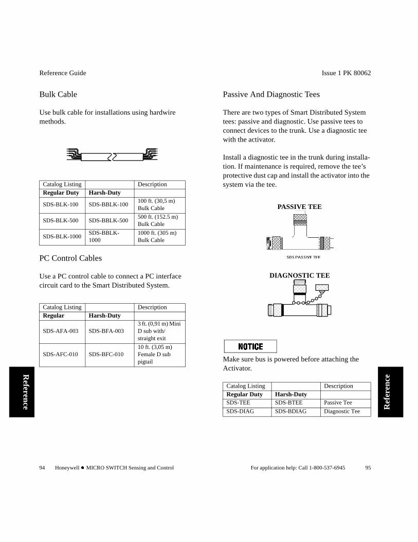
Reference Guide
94 Honeywell l MICRO SWITCH Sensing and Control
Reference
Bulk Cable
Use bulk cable for installations using hardwire methods.
PC Control Cables
Use a PC control cable to connect a PC interface circuit card to the Smart Distributed System.
Catalog Listing DescriptionRegular Duty Harsh-Duty
SDS-BLK-100 SDS-BBLK-100100 ft. (30,5 m) Bulk Cable
SDS-BLK-500 SDS-BBLK-500500 ft. (152.5 m) Bulk Cable
SDS-BLK-1000SDS-BBLK-1000
1000 ft. (305 m) Bulk Cable
Catalog Listing DescriptionRegular Harsh-Duty
SDS-AFA-003 SDS-BFA-0033 ft. (0,91 m) Mini D sub with/straight exit
SDS-AFC-010 SDS-BFC-01010 ft. (3,05 m) Female D sub pigtail
Issue 1 PK 80062
For application help: Call 1-800-537-6945 95
Ref
eren
ce
Passive And Diagnostic Tees
There are two types of Smart Distributed System tees: passive and diagnostic. Use passive tees to connect devices to the trunk. Use a diagnostic tee with the activator.
Install a diagnostic tee in the trunk during installa-tion. If maintenance is required, remove the tee’s protective dust cap and install the activator into the system via the tee.
Make sure bus is powered before attaching the Activator.
PASSIVE TEE
DIAGNOSTIC TEE
Catalog Listing DescriptionRegular Duty Harsh-DutySDS-TEE SDS-BTEE Passive Tee
SDS-DIAG SDS-BDIAG Diagnostic Tee

Reference Guide
96 Honeywell l MICRO SWITCH Sensing and Control
Reference
Male And Female Terminators
Use a termination cap to match the impedance of the signal communication lines on the bus, pre-venting signal reflection. A cap consists of a 120Ω resistor between the Bus+ and Bus– contacts inside a molded connector body.
The Smart Distributed System bus must be termi-nated at each end with a 120 ohm resistor between the BUS+ and BUS- connectors. When the bus ends at a tee, use a termination cap.
FEMALE TERMINATION CAP
MALE TERMINATION CAP
Catalog Listing DescriptionRegular Duty Harsh-Duty
SDS-TERM SDS-BTERMMale Termination Cap
SDS-TERM-F SDS-BTERM-FFemale Termination Cap
Female
Male Pin
Contacts
Issue 1 PK 80062
For application help: Call 1-800-537-6945 97
Ref
eren
ce
Mini And Micro Dust Caps
Mini and micro dust caps prevent dirt from enter-ing unused tee and multiport connectors. The caps also help prevent system short circuits.
Catalog Listing Description
SDS-CAP-MEXT Mini dust cap with external threads
SDS-CAP-MINT Mini dust cap with internal threads
SDS-CAP-MCROMicro dust cap with external threads

Reference Guide
98 Honeywell l MICRO SWITCH Sensing and Control
Reference
Bulkhead Connectors
Use bulkhead connectors to connect the Smart Distributed System bus through walls or electrical enclosure bulkheads.
Catalog Listing DescriptionRegular Duty Harsh-Duty
SDS-BKHD -001SDS-BBKHD-001
0.5 ft. (0,15 m) female Bulkhead Cable
SDS-BKHD-003SDS-BBKHD-003
3 ft. (0,91 m) female Bulkhead Cable
SDS-BKHD-006SDS-BBKHD-006
6 ft. (1,83 m) female Bulkhead Cable
SDS-BKHD-010SDS-BBKHD-010
10 ft. (3,05 m) female Bulkhead Cable
SDS-BKHD-M-001-003-006-010
N/A Male Bulkheads
Issue 1 PK 80062
For application help: Call 1-800-537-6945 99
Ref
eren
ce
Activator Cables
The activator comes with a mini-connector cable, micro-connector cable, Quad I/O Concentrator cable, and a diagnostic tee. If needed, you can order extra cables.
See passive and diagnostic tee catalog listings to order a diagnostic tee. We recommend that you mount a diagnostic tee permanently into each Smart Distributed System bus for easy activator installation.
Catalog Listing Description
Regular Duty
SDS-ACTAMini connector cable6 ft. (1,83 m)
SDS-ACTB Micro connector cable 3 ft. (0,91 m)
SDS-ACTS5-Pin European cable connector, 3ft. (0.91m)

Reference Guide
100 Honeywell l MICRO SWITCH Sensing and Control
Reference
Field Terminatable Plug And Receptacle Connectors
The field terminatable plug and receptacle connec-tors allow you to cut cable to a specified length. These products provide you with the ability to cus-tomize your cabling requirements and install con-nectors where convenient.
Accessory (Multiport) Cables
Accessory cables come in two types: actuator and sensor multiport. Use these cables to connect non-Smart Distributed System devices to actuator or sensor multiports. Use these yellow cables with non-bus products.
Catalog Listing Description
SDS-FTCFMini female field terminatable plug connector
SDS-FTCMMini male field terminatable receptacle connector
Issue 1 PK 80062
For application help: Call 1-800-537-6945 101
Ref
eren
ce
Actuator Multiport Cables
Use actuator multiport cables to connect non-Smart Distributed System devices to actuator mul-tiports. All are 3-pin.
MINI-MINI ACTUATOR MULTIPORT POWER/OUTPUT CABLE
FEMALE END=STRAIGHT PLUGMALE END=STRAIGHT PLUG
MINI MALE PIGTAIL ACTUATOR MULTIPORT POWER/OUTPUT CABLE
MALE END=STRAIGHT PLUG
Catalog Listing Description
84914-0070 3 ft. (0,91 m)
84914-0071 6 ft. (1,83 m)
84914-0072 9 ft. (2,74 m)
84914-0073 12 ft. (3,66 m)
84914-0074 20 ft. (6,10 m)
84914-0085 25 ft. (7,62 m)
84914-0086 50 ft. (15,24 m)
Catalog Listing Description
14341M11 3 ft. (0,91 m)
14342M12 6 ft. (1,83 m)
14343M11 9 ft. (2,74 m)
14344M11 12 ft. (3,66 m)
14345M11 20 ft. (6,10 m)
14346M11 25 ft. (7,62 m)
14347M11 50 ft. (15,24 m)

Reference Guide
102 Honeywell l MICRO SWITCH Sensing and Control
Reference
MINI MALE PIGTAIL ACTUATOR MULTIPORT POWER/OUTPUT CABLE
MALE END=RIGHT ANGLE PLUG
MINI FEMALE PIGTAIL ACTUATOR MULTI-PORT POWER/OUTPUT CABLE
FEMALE END=STRAIGHT PLUG
Catalog Listing Description
14341K11 3 ft. (0,91 m)
14342K11 6 ft. (1,83 m)
14343K11 9 ft. (2,74 m)
14344K11 12 ft. (3,66 m)
14345K11 20 ft. (6,10 m)
14346K11 25 ft. (7,62 m)
14347K11 50 ft. (15,24 m)
Catalog Listing Description
14341M01 3 ft. (0,91 m)
14342M01 6 ft. (1,83 m)
14343M01 9 ft. (2,74 m)
14344M01 12 ft. (3,66 m)
14345M01 20 ft. (6,10 m)
14346M01 25 ft. (7,62 m)
14347M01 50 ft. (15,24 m)
Issue 1 PK 80062
For application help: Call 1-800-537-6945 103
Ref
eren
ce
MINI FEMALE PIGTAIL ACTUATOR MULTI-PORT POWER/OUTPUT CABLE
FEMALE END=RIGHT ANGLE PLUG
Catalog Listing Description
14341K01 3 ft. (0,91 m)
14342K01 6 ft. (1,83 m)
14343K01 9 ft. (2,74 m)
14344K01 12 ft. (3,66 m)
14345K01 20 ft. (6,10 m)
14346K01 25 ft. (7,62 m)
14347K01 50 ft. (15,24 m)

Reference Guide
104 Honeywell l MICRO SWITCH Sensing and Control
Reference
Sensor Multiport Cables
Use sensor multiport cables to connect non-Smart Distributed System devices to sensor multiports. All are 4-pin.
MINI-MINI SENSOR MULTIPORT INPUT CABLE
FEMALE END=STRAIGHT PLUGMALE END=STRAIGHT PLUG
MINI MALE PIGTAIL SENSOR MULTIPORT INPUT CABLE
MALE END=STRAIGHT PLUG
Catalog Listing Description
84914-0075 3 ft. (0,91 m)
84914-0076 6 ft. (1,83 m)
84914-0077 9 ft. (2,74 m)
84914-0078 12 ft. (3,66 m)
84914-0079 20 ft. (6,10 m)
84914-0080 25 ft. (7,62 m)
84914-0081 50 ft. (15,24 m)
Catalog Listing Description
14441M11 3 ft. (0,91 m)
14442M11 6 ft. (1,83 m)
14443M11 9 ft. (2,74 m)
14444M11 12 ft. (3,66 m)
14445M11 20 ft. (6,10 m)
14446M11 25 ft. (7,62 m)
14447M11 50 ft. (15,24 m)
Issue 1 PK 80062
For application help: Call 1-800-537-6945 105
Ref
eren
ce
MINI MALE PIGTAIL SENSOR MULTIPORT INPUT CABLE
MALE END=RIGHT ANGLE PLUG
MICRO-MICRO SENSOR MULTIPORT INPUT CABLE
FEMALE END=STRAIGHT PLUGMALE END=STRAIGHT RECEPTACLE
Catalog Listing Description
14441K11 3 ft. (0,91 m)
14442K11 6 ft. (1,83 m)
14443K11 9 ft. (2,74 m)
14444K11 12 ft. (3,66 m)
14445K11 20 ft. (6,10 m)
14446K11 25 ft. (7,62 m)
14447K11 50 ft. (15,24 m)
Catalog Listing Description
84908-0165 3 ft. (0,91 m)
84908-0166 6 ft. (1,83 m)
84908-0167 9 ft. (2,74 m)
84908-0168 12 ft. (3,66 m)
84908-0169 20 ft. (6,10 m)
84908-0200 25 ft. (7,62 m)
84908-0201 50 ft. (15,24 m)
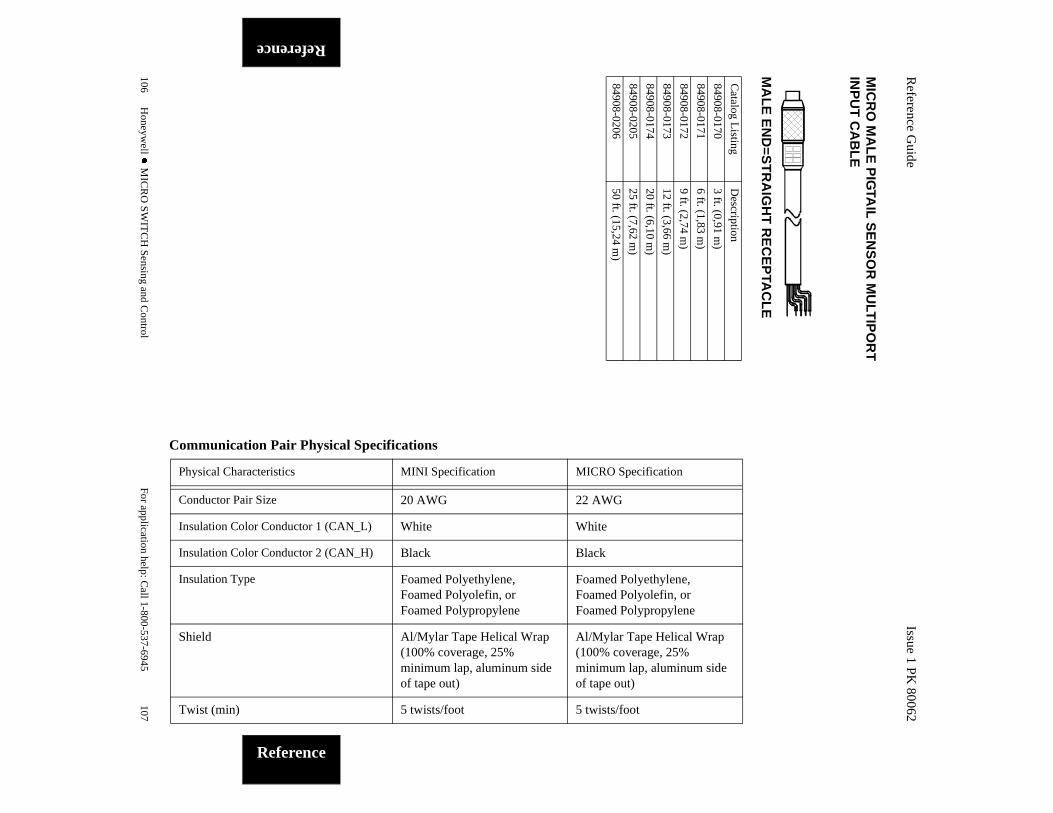
Reference G
uide
106H
oneywell l M
ICR
O S
WIT
CH
Sensing and C
ontrol
Reference
MIC
RO
MA
LE
PIG
TAIL
SE
NS
OR
MU
LTIP
OR
T
INP
UT
CA
BL
E
MA
LE
EN
D=S
TR
AIG
HT
RE
CE
PTA
CL
E
Catalog L
istingD
escription
84908-01703 ft. (0,91 m
)
84908-01716 ft. (1,83 m
)
84908-01729 ft. (2,74 m
)
84908-017312 ft. (3,66 m
)
84908-017420 ft. (6,10 m
)
84908-020525 ft. (7,62 m
)
84908-020650 ft. (15,24 m
)
Issue 1 PK
80062
For application help: C
all 1-800-537-6945107
Reference
Physical Characteristics MINI Specification MICRO Specification
Conductor Pair Size 20 AWG 22 AWG
Insulation Color Conductor 1 (CAN_L) White White
Insulation Color Conductor 2 (CAN_H) Black Black
Insulation Type Foamed Polyethylene, Foamed Polyolefin, or Foamed Polypropylene
Foamed Polyethylene, Foamed Polyolefin, or Foamed Polypropylene
Shield Al/Mylar Tape Helical Wrap (100% coverage, 25% minimum lap, aluminum side of tape out)
Al/Mylar Tape Helical Wrap (100% coverage, 25% minimum lap, aluminum side of tape out)
Twist (min) 5 twists/foot 5 twists/foot
Communication Pair Physical Specifications
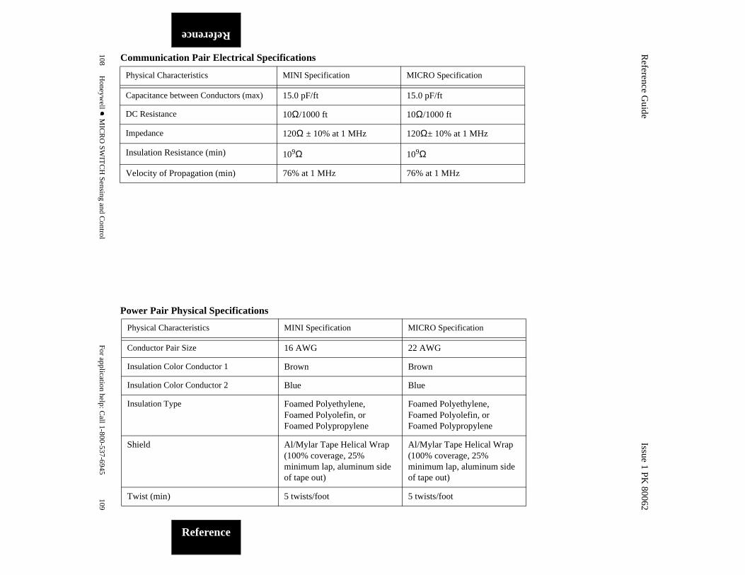
Reference G
uide
108H
oneywell l M
ICR
O S
WIT
CH
Sensing and C
ontrol
Reference
Physical Characteristics MINI Specification MICRO Specification
Capacitance between Conductors (max) 15.0 pF/ft 15.0 pF/ft
DC Resistance 10Ω/1000 ft 10Ω/1000 ft
Impedance 120Ω ± 10% at 1 MHz 120Ω± 10% at 1 MHz
Insulation Resistance (min) 109Ω 109Ω
Velocity of Propagation (min) 76% at 1 MHz 76% at 1 MHz
Communication Pair Electrical Specifications
Issue 1 PK
80062
For application help: C
all 1-800-537-6945109
Reference
Physical Characteristics MINI Specification MICRO Specification
Conductor Pair Size 16 AWG 22 AWG
Insulation Color Conductor 1 Brown Brown
Insulation Color Conductor 2 Blue Blue
Insulation Type Foamed Polyethylene, Foamed Polyolefin, or Foamed Polypropylene
Foamed Polyethylene, Foamed Polyolefin, or Foamed Polypropylene
Shield Al/Mylar Tape Helical Wrap (100% coverage, 25% minimum lap, aluminum side of tape out)
Al/Mylar Tape Helical Wrap (100% coverage, 25% minimum lap, aluminum side of tape out)
Twist (min) 5 twists/foot 5 twists/foot
Power Pair Physical Specifications

Reference G
uide
110H
oneywell l M
ICR
O S
WIT
CH
Sensing and C
ontrol
Reference
Power Pair Electrical Specifications
Physical Characteristics MINI Specification MICRO Specification
Resistance (max) 4.3Ω/1000 ft 4.3Ω/1000 ft
Physical Characteristics MINI Specification MICRO Specification
Conductor Size 20 AWG stranded, tinned copper
22 AWG stranded, tinned copper
Resistance (max) 10Ω/1000 ft 17Ω/1000 ft
Power Pair Physical Specifications (continued)
Issue 1 PK
80062
For application help: C
all 1-800-537-6945111
Reference
Notes:

Reference Guide
112 Honeywell l MICRO SWITCH Sensing and Control
Reference
Notes:
Issue 1 PK 80062
For application help: Call 1-800-537-6945 113
Ref
eren
ce
Notes:

Reference Guide
114 Honeywell l MICRO SWITCH Sensing and Control
Reference
Notes:
Issue 1 PK 80062
For application help: Call 1-800-537-6945 115
Ref
eren
ce
Notes:

Reference Guide
116 Honeywell l MICRO SWITCH Sensing and Control
Reference
Notes:
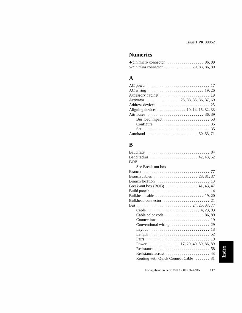
Issue 1 PK 80062
For application help: Call 1-800-537-6945 117
Inde
x
Numerics4-pin micro connector . . . . . . . . . . . . . . . . . . 86, 895-pin mini connector . . . . . . . . . . . . . 29, 83, 86, 89
AAC power . . . . . . . . . . . . . . . . . . . . . . . . . . . . . . . 17AC wiring . . . . . . . . . . . . . . . . . . . . . . . . . . . . 19, 26Accessory cabinet . . . . . . . . . . . . . . . . . . . . . . . . . 19Activator . . . . . . . . . . . . . . . . . 25, 33, 35, 36, 37, 69Address devices . . . . . . . . . . . . . . . . . . . . . . . . . . 25Aligning devices . . . . . . . . . . . . . . 10, 14, 15, 32, 33Attributes . . . . . . . . . . . . . . . . . . . . . . . . . . . . 36, 39
Bus load impact . . . . . . . . . . . . . . . . . . . . . . . 53Configure . . . . . . . . . . . . . . . . . . . . . . . . . . . 35Set . . . . . . . . . . . . . . . . . . . . . . . . . . . . . . . . . 35
Autobaud . . . . . . . . . . . . . . . . . . . . . . . . . 50, 53, 71
BBaud rate . . . . . . . . . . . . . . . . . . . . . . . . . . . . . . . 84Bend radius . . . . . . . . . . . . . . . . . . . . . . . . 42, 43, 52BOB
See Break-out boxBranch . . . . . . . . . . . . . . . . . . . . . . . . . . . . . . . . . 77Branch cables . . . . . . . . . . . . . . . . . . . . . . 23, 31, 37Branch location . . . . . . . . . . . . . . . . . . . . . . . . . . 13Break-out box (BOB) . . . . . . . . . . . . . . . . 41, 43, 47Build panels . . . . . . . . . . . . . . . . . . . . . . . . . . . . . 14Bulkhead cable . . . . . . . . . . . . . . . . . . . . . . . . 19, 20Bulkhead connector . . . . . . . . . . . . . . . . . . . . . . . 21Bus . . . . . . . . . . . . . . . . . . . . . . . . . . . 24, 25, 37, 77
Cable . . . . . . . . . . . . . . . . . . . . . . . . . . 4, 23, 83Cable color code . . . . . . . . . . . . . . . . . . . 86, 89Connections . . . . . . . . . . . . . . . . . . . . . . . . . . 19Conventional wiring . . . . . . . . . . . . . . . . . . . 29Layout . . . . . . . . . . . . . . . . . . . . . . . . . . . . . . 13Length . . . . . . . . . . . . . . . . . . . . . . . . . . . . . . 52Pairs . . . . . . . . . . . . . . . . . . . . . . . . . . . . . . . . 19Power . . . . . . . . . . . . . . . 17, 29, 49, 50, 86, 89Resistance . . . . . . . . . . . . . . . . . . . . . . . . . . . 58Resistance across . . . . . . . . . . . . . . . . . . . . . . 43Routing with Quick Connect Cable . . . . . . . 31

Reference Guide
118 Honeywell l MICRO SWITCH Sensing and Control
Index
Shielding . . . . . . . . . . . . . . . . . . . . . . . . . .86, 89Connection to ground . . . . . . . . . . . . . . .19
Speed . . . . . . . . . . . . . . . . . . . . . . . . . .50, 52, 84Traffic . . . . . . . . . . . . . . . . . . . . . . . . . . . . . . .65
Bus-Off . . . . . . . . . . . . . . . . . . . . . . . . . . . . . . . . .56
CCable . . . . . . . . . . . . . . . . . . . . . . . . . . .5, 10, 18, 83
Accessory . . . . . . . . . . . . . . . . . . . . . . . . . . .100Activator . . . . . . . . . . . . . . . . . . . . . . . . . . . . .99Actuator multiport . . . . . . . . . . . . . . . . . . . .101Branch . . . . . . . . . . . . . . . . . . . . . .31, 37, 84, 91Bulk . . . . . . . . . . . . . . . . . . . . . . . . . . . . . . . . .94Bus communications . . . . . . . . . . . . . . . . . . . .89Bus power . . . . . . . . . . . . . . . . . . . . . . . . . . . .89Color code . . . . . . . . . . . . . . . . . . . . . . . . .86, 89Connections
Quick connect . . . . . . . . . . . . . . . . . . . . .31Hardwire . . . . . . . . . . . . . . . . . . . . . . . . . . . . .25Length . . . . . . . . . . . . . . . . . . . . . . . . .13, 23, 84Micro . . . . . . . . . . . . . . . . . . . . . . . . . . . . . . . .31Micro male pigtail sensor multiport . . . . . . .106Micro-micro sensor multiport input . . . . . . .105Mini . . . . . . . . . . . . . . . . . . . . . . . . . . . . . . . . .31Mini female pigtail actuator multiport power/
output . . . . . . . . . . . . . . . . . . .102, 103Mini male pigtail actuator multiport power/
output . . . . . . . . . . . . . . . . . . .101, 102Mini male pigtail sensor multiport input . . 104,
105Mini-min actuator multiport power/output . .101Mini-mini sensor multiport input . . . . . . . . .104PC Control . . . . . . . . . . . . . . . . . . . . . . . . . . .94Pigtail . . . . . . . . . . . . . . . . . . . . . . . . . . . .92, 93Pigtail branch . . . . . . . . . . . . . . . . . . . . . . . . .91Plug-and-Play . . . . . . . . . . . . . . . . . . . . . .22, 88Quick connect . . . . . . . . . . . . . . . . . . . . . .22, 83Right-angle female micro connector . . . . . . .92Right-angle female mini connector . . . . .90, 92Sensor multiport . . . . . . . . . . . . . . . . . . . . . .104Shielding . . . . . . . . . . . . . . . . . . . . . . . . . .83, 89Straight female micro . . . . . . . . . . . . . . . . . . .91
Issue 1 PK 80062
For application help: Call 1-800-537-6945 119
Inde
x
Straight female mini connector . . . . . . . . 90, 91Straight male mini connector . . . 90, 91, 92, 93Trunk . . . . . . . . . . . . . . . . . . . . . . . . . . . . . . . 90
CAN . . . . . . . . . . . . . . . . . . . . . . 5, 6, 61, 77, 84, 88Commission system . . . . . . . . . . . . . . . . . 10, 40, 41Commissioning Checklist . . . . . . . . . . . . . . . . . . 52Communications . . . . . . . . . . . . . . . . . . . . . . . . . . . 5Communications problems . . . . . . . . . . . . . . . . . . 64Configure system . . . . . . . . . . . . . . . . . . . . . . 10, 35Connections
Bulkhead . . . . . . . . . . . . . . . . . . . . . . . . . . . . 43Hardwired . . . . . . . . . . . . . . . . . . . . . . . . . . . 43Pigtail . . . . . . . . . . . . . . . . . . . . . . . . . . . . . . 43Plug-and-play . . . . . . . . . . . . . . . . . . . . . 31, 42
ConnectorsBulkheak . . . . . . . . . . . . . . . . . . . . . . . . . . . . 98Dust caps . . . . . . . . . . . . . . . . . . . . . . . . . . . . 97Field terminated . . . . . . . . . . . . . . . . . . . . . . 22Strain relief . . . . . . . . . . . . . . . . . . . . . . . . . . 31
Control cabinet . . . . . . . . . . . . . . . . . . . . . . . . . . . 20Control panels
Build and install . . . . . . . . . . . . . . . . 15, 16, 17Layout . . . . . . . . . . . . . . . . . . . . . . . . . . . . . . 13
Controller . . . . . . . . . . . . . . . . . . . . 4, 17, 24, 25, 26Setup . . . . . . . . . . . . . . . . . . . . . . . . . 35, 38, 39
Controller Area Network (CAN) protocolSee CAN
ControllersNon-Honeywell . . . . . . . . . . . . . . . . . . . . . . . 73
DDC power . . . . . . . . . . . . . . . . . . . . . . . . . . . . . . . 29Device . . . . . . . . . . . . . . . . . . . . . . . . . . . . . . . . . . 78
Address . . . . . . . . . . . . . . . . . . . . . . . . . . . . . 37Align . . . . . . . . . . . . . . . . . . . . . . . . . . . . . . . 46Attributes . . . . . . . . . . . . . . . . . . . 36, 39, 51, 53Cabinet . . . . . . . . . . . . . . . . . . . . . . . . . . . . . 21Configure . . . . . . . . . . . . . . . . . . . . . 35, 36, 37Diagnostics . . . . . . . . . . . . . . . . . . . . . . . . . . . 5Fails to respond . . . . . . . . . . . . . . . . . . . . . . . 56Location . . . . . . . . . . . . . . . . . . . . . . . . . . . . 13Mount and align . . . . . . . . . . . . . . . . . . . . . . 33

Reference Guide
120 Honeywell l MICRO SWITCH Sensing and Control
Index
Operation erratic, intermittent . . . . . . . . . . . .56Power requirements . . . . . . . . . . . . . . . . . . . .13Reaction time . . . . . . . . . . . . . . . . . . . . . . . . .53
Digital multimeter (DMM) . . . . . . . . . . . .41, 43, 47DMM
See Digital multimeterDocument system . . . . . . . . . . . . . . . . . . . . . . . . . .10Duplicate Node . . . . . . . . . . . . . . . . . . . . . . . . . . .56Dust cap
Micro . . . . . . . . . . . . . . . . . . . . . . . . . . . . . . . .97Mini . . . . . . . . . . . . . . . . . . . . . . . . . . . . . . . . .97
EEarth ground . . . . . . . . . . . . . . . . . . . . . . . . . . . . .18Electrical load
See LoadE-mail address . . . . . . . . . . . . . . . . . . . . . . . . . . . . .7EMI . . . . . . . . . . . . . . . . . . . . . . . . . . . . . . . . . . . .65Enrollment . . . . . . . . . . . . . . . . . . . . . . . . . . . . . . .71Error 100 . . . . . . . . . . . . . . . . . . . . . . . . . . . . .72, 74Error 20 . . . . . . . . . . . . . . . . . . . . . . . . . . . . . .72, 74Error 40 . . . . . . . . . . . . . . . . . . . . . . . . . . .56, 72, 74Error 80 . . . . . . . . . . . . . . . . . . . . . . . . . . . . . .72, 74Error frames . . . . . . . . . . . . . . . . . . . . . . . . . . . . . .62
FField Terminatable Connectors . . . . . . . .22, 29, 100Fuse . . . . . . . . . . . . . . . . . . . . . . . . . . . . . . . . . . . .18
GGE Fanuc/Horner Electric 90/30 . . . . . . . . . . . . . .38Global Diagnostic Register . . . . . . . . . . . . . . .72, 73
HHand-Held Activator . . . . . . . . . . .33, 35, 36, 37, 69Hardwire cable . . . . . . . . . . . . . . . . . . . . . . . . . . . .25Hardwired connections . . . . . . . . . . . . . . . . . . . . . .5Hardwiring . . . . . . . . . . . . . . . . . . . . . . . . . . . . . . .22Honeywell
CAN Error Monitor . . . . . . . . . . . . . . . . . . . .69
Issue 1 PK 80062
For application help: Call 1-800-537-6945 121
Inde
x
Customer Response Center . . . . . . . . . . . . . . 66Hand-Held Activator . . . . . . . 33, 35, 36, 37, 69Interface Terminal Strip . . . . . . . . . . . . . . . . 38Network Manager . . . . . . . . . . . . . . . . . . . . . 65PC 620 . . . . . . . . . . . . . . . . . . . . . . . . . . . . . . 38PC Interface Card . . . . . . . . . . . . . . . . . . 69, 71SDSMON . . . . . . . . . . . . . . . . . . . . . . . . . . . 69Smart ControlPC . . . . . . . . . . . . . . . . . . . . . . 38
Honeywell VME Interface . . . . . . . . . . . . . . . . . . 38Host baud rate . . . . . . . . . . . . . . . . . . . . . . . . . . . . 52
II/O interfaces . . . . . . . . . . . . . . . . . . . . . . . . . . . . . 4Install
Cable . . . . . . . . . . . . . . . . . . . . . . 14, 15, 22, 23Components . . . . . . . . . . . . . . . . . . . . . . 10, 14Panels . . . . . . . . . . . . . . . . . . . . . . . . . . . 10, 14Tees . . . . . . . . . . . . . . . . . . . . . . . 14, 15, 22, 23
Interface cardInternal resistor . . . . . . . . . . . . . . . . . . . . . . . 25
Internet e-mail address . . . . . . . . . . . . . . . . . . . . . . 7
LLoads . . . . . . . . . . . . . . . . . . . 37, 42, 45, 46, 52, 78Logical address . . . . . . . . . . . . . . . . . . . . . . . . . . . 78Logical device . . . . . . . . . . . . . . . . . . . . . . . . . . . 78Logical state . . . . . . . . . . . . . . . . . . . . . . . . . . . . . 79
MMachine layout . . . . . . . . . . . . . . . . . . . . . . . . . . . 13Micro cable
Bend radius . . . . . . . . . . . . . . . . . . . . 42, 43, 52Micro cables . . . . . . . . . . . . . . . . . . . . . . . . . . . . . 31Mini Cable . . . . . . . . . . . . . . . . . . . . . . . . . . . . . . 31Mini cable
Bend radius . . . . . . . . . . . . . . . . . . . . 42, 43, 52Missing Node errors . . . . . . . . . . . . . . . . . . . . 56, 64Motor control cabinet . . . . . . . . . . . . . . . . . . . . . . 21Mount devices . . . . . . . . . . . . . . . . . . . . . . . . . . . 33Multiple binary object . . . . . . . . . . . . . . . . . . . . . 79Multiple embedded object . . . . . . . . . . . . . . . . . . 79

Reference Guide
122 Honeywell l MICRO SWITCH Sensing and Control
Index
NNeeds analysis . . . . . . . . . . . . . . . . . . . . . . . . . .2, 13Network . . . . . . . . . . . . . . . . . . . . . . . . . . . . . . . . .79Network data . . . . . . . . . . . . . . . . . . . . . . . . . . . . .79Network errors . . . . . . . . . . . . . . . . . . . . . . . . . . . .56Network Manager . . . . . . . . . . . . . . . . . . .39, 53, 65Network variable . . . . . . . . . . . . . . . . . . . . . . . . . .79Node . . . . . . . . . . . . . . . . . . . . . . . . . . . . . . . . . . . .79Notice . . . . . . . . . . . . . . . . . . . . . . . . . . . . . . . . . . . .3
OObject model . . . . . . . . . . . . . . . . . . . . . . . . . . . . .80Output . . . . . . . . . . . . . . . . . . . . . . . . . . . . . . . . . .80
PPanel layout . . . . . . . . . . . . . . . . . . . . . . . . . . . . . .17PC cable . . . . . . . . . . . . . . . . . . . . . . . . . . . . . . . . .20Physical component . . . . . . . . . . . . . . . . . . . . . . . .80Physical Layer specification . . . . . . . . . . . . . . . . . .6Pigtail cable . . . . . . . . . . . . . . . . . .19, 20, 21, 22, 29PLC . . . . . . . . . . . . . . . . . . . . . . . . . . . . . . . . .37, 39PLC Direct 405 . . . . . . . . . . . . . . . . . . . . . . . . . . .38Plug-and-play
Connections . . . . . . . . . . . . . . . . . . . . . . . . . .45Polarity . . . . . . . . . . . . . . . . . . . . . . . . . . . . . . . . . .47Power
Consumption . . . . . . . . . . . . . . . . . . . . . . . . . .17Pair . . . . . . . . . . . . . . . . . . . . . . . . . . . . . . . . .19Sequencing . . . . . . . . . . . . . . . . . . . . . . . . . . .74
Power cycle . . . . . . . . . . . . . . . . . . . . . . . . . . . . . .80Power supply . . . . . . . . . . . .4, 13, 17, 24, 25, 26, 46
Bus . . . . . . . . . . . . . . . . . . . . . . . . . . . . . . . . .20Cabinet . . . . . . . . . . . . . . . . . . . . . . . . . . .18, 19Considerations . . . . . . . . . . . . . . . . . . . . . . . .27Sizing . . . . . . . . . . . . . . . . . . . . . . . . . . . . . . .49Voltages . . . . . . . . . . . . . . . . . . . . . . .46, 49, 58
Power up . . . . . . . . . . . . . . . . . . . . . . . . . . . . . . . .80Power Up Checklist . . . . . . . . . . . . . . .10, 40, 46, 47Pre-Control Program Execution Checklist 10, 40, 50,
. . . . . . . . . . . . . . . . . . . . . . . . . . . . . .51Pre-installation planning . . . . . . . . . . . . . . . . . . . . .2
Issue 1 PK 80062
For application help: Call 1-800-537-6945 123
Inde
x
Pre-Power Up Checklist . . . . . . . . 10, 40, 41, 42, 43
QQuick connect cable connections . . . . . . . . . . . . . 31Quick connect hardware . . . . . . . . . . . . . . . . . . . . . 5
RRegister . . . . . . . . . . . . . . . . . . . . . . . . . . . . . . . . . 80
SScrew-terminal connections . . . . . . . . . . . . . . . . . 42SDSTOOLS . . . . . . . . . . . . . . . . . . . . . . . . . . 65, 73Service . . . . . . . . . . . . . . . . . . . . . . . . . . . . . . . . . . 7Set attributes . . . . . . . . . . . . . . . . . . . . . . . . . . . . . 35Setup Controller . . . . . . . . . . . . . . . . . . . . . . . 38, 39Shield
Drain-wire . . . . . . . . . . . . . . . . . . 18, 42, 43, 52Power supply cabinet . . . . . . . . . . . . . . . . . . 28
Siemens S5 . . . . . . . . . . . . . . . . . . . . . . . . . . . . . . 38Smart devices . . . . . . . . . . . . . . . . . . . . . . . . . . . 4, 5Smart Distributed System
Controller . . . . . . . . . . . . . . . . . . . . . . . . . . . 47Host . . . . . . . . . . . . . . . . . . . . . . . . . . . . . . . . 80Interface card . . . . . . . . . . . . . . . . . . . . . . . . . 39Network Manager . . . . . . . . . . . . . . . . . . 39, 53
Strain relief . . . . . . . . . . . . . . . . . . . . . . . . . . . . . . 21System design . . . . . . . . . . . . . . . . . . . . . . . . . . 2, 13System Integration . . . . . . . . . . . . . . . . . . . . . 10, 40System power . . . . . . . . . . . . . . . . . . . . . . . . . . . . . 5
TTechnical Support . . . . . . . . . . . . . . . . . . . . . . . . . 7Tees . . . . . . . . . . . . . . . . . . . . . . . 10, 23, 31, 81, 83
Diagnostic . . . . . . . . . . . . . . . . . . . . . . . . . . . 95Mounting . . . . . . . . . . . . . . . . . . . . . . . . . . . . 30Passive . . . . . . . . . . . . . . . . . . . . . . . . . . . . . . 95
Terminal blocks . . . . . . . . . . . . . . . . . . . . . . . 22, 29Terminal strip . . . . . . . . . . . . . . . . . . . . . . . . . 21, 26Terminating resistors 4, 23, 24, 25, 26, 42, 43, 47, 52,
. . . . . . . . . . . . . . . . . . . . . . . . . . . . . 81

Reference Guide
124 Honeywell l MICRO SWITCH Sensing and Control
Index
Termination caps . . . . . . . . . . . . . . . . . . . . . .96Termination cap . . . . . . . . . . . . . . . . . . . . . . . .25, 96Tips . . . . . . . . . . . . . . . . . . . . . . . . . . . . . . . . . . . . .3Topology . . . . . . . . . . . . . . . . . . . . . . . . . . . . .81, 88Traffic load . . . . . . . . . . . . . . . . . . . . . . . . . . . .50, 51Transmission rate . . . . . . . . . . . . . . . . . . . . . . . . . .84Trunk . . . . . . . . . . . . . . . . . . . . . . . . . . . . . . . . . . .81
VVector CANalyzer . . . . . . . . . . . . . . . . . . . . . . . . .69Voltage drop . . . . . . . . . . . . . . . . . . . . . . . . . . . . .81
WWiring diagram . . . . . . . . . . . . . . . . . . . . . . . .13, 17World Wide Web address . . . . . . . . . . . . . . . . . . . .7WWW address . . . . . . . . . . . . . . . . . . . . . . . . . . . . .7

Issue 1 PK 80062
For application help: Call 1-800-537-6945 125
Sales and Service
Honeywell serves its customers through a world-wide network of sales offices and distributors. Contact a nearby sales office for application assis-tance, current specifications, pricing, or the name of the nearest authorized distributor.
Or contact:
MICRO SWITCHHoneywell, Inc.11 W. Spring StreetFreeport, Illinois 61032
For application assistance:1-800-537-6945 USA1-800-737-3360 Canada1-815-235-6847 International
INTERNET E-MAIL [email protected]
INTERNET WORLD WIDE WEB ADDRESSEShttp://www.honeywell.com/sensing/http://www.honeywell.com/sensing/prodinfo/sds/
While we provide application assistance for Honeywell products, personally and through our literature, it is up to the customer to determine the suitability of the product in the application.

Issue 1 PK 80062
For application help: Call 1-800-537-6945 126
MICRO SWITCHHoneywell Inc.11 West Spring St.Freeport, IL 61032U.S. 800-537-6945Canada 800-737-3360International 815-235-6847