Embed Size (px)
Citation preview
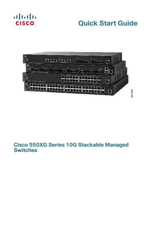
Quick Start Guide
Cisco 550XG Series 10G Stackable Managed Switches
40
13
32
Welcome
Thank you for choosing the Cisco 550XG Series 10G Stackable Managed Switch, a Cisco network communications device. This device is designed to be operational right out-of-the-box as a standard layer 2 and 3 switch. In the default configuration, it will forward packets between connecting devices after power up.
This guide familiarizes you with the layout of the switch and describes how to deploy the switch in your network. For additional information, see www.cisco.com/go/550switches.
Package Contents
• Cisco 550XG�10G Stackable Managed Switch
• Power Cord
• Rack-Mount Kit and Rubber Feet
• DB-9 to RJ45 Serial Cable
• This Quick Start Guide
• Pointer Card with China RoHS
• Technical Support Contacts
• EU Directives 1999/5/EC Compliance Information (for EU SKU only)
Before You Begin
Before you begin the installation, make sure that you have the following:
• RJ-45 Ethernet cables (Category 6A or higher) for connecting network devices.
• Console cable for using the console port to manage your switch.
• Tools for installing the hardware. The rack-mount kit packed with the switch contains four rubber feet for desktop placement, and two brackets and twelve screws for rack-mounting.
• PC with Internet Explorer (version 8.0, 9.0, 10.0, or higher) or Firefox (version 16.0, 17.0, or higher) for using the web-based interface or the console port to manage your switch.
1
2 Cisco 550XG Series 10G Stackable Switches Quick Start Guide
Mounting the Cisco 550XG Switches
There are two ways to physically install the switch:
• Place the switch on a flat surface. To place the switch on a desktop, install the four rubber feet (included) on the bottom of the switch.
• Mount the switch in a standard rack (1 rack unit high).
Placement Tips
Do not deploy the switch in a location where any of the following conditions exist:
• Ambient Temperature—To prevent the switch from overheating, do not operate it in an area that exceeds an ambient temperature of 122°F (50°C).
• Air Flow—Be sure that there is adequate air flow around the switch.
• Mechanical Loading—Be sure that the switch is level and stable to avoid any hazardous conditions.
• Circuit Overloading—Adding the switch to the power outlet must not overload that circuit.
Rack Mounting
You can mount the switch in any standard size, 19-inch (about 48 cm) wide rack. The switch requires 1 rack unit (RU) of space, which is 1.75 inches (44.45 mm) high.
CAUTION For stability, load the rack from the bottom to the top, with the heaviest devices on the bottom. A top-heavy rack is likely to be unstable and might tip over.
2
Cisco 550XG Series 10G Stackable Switches Quick Start Guide 3
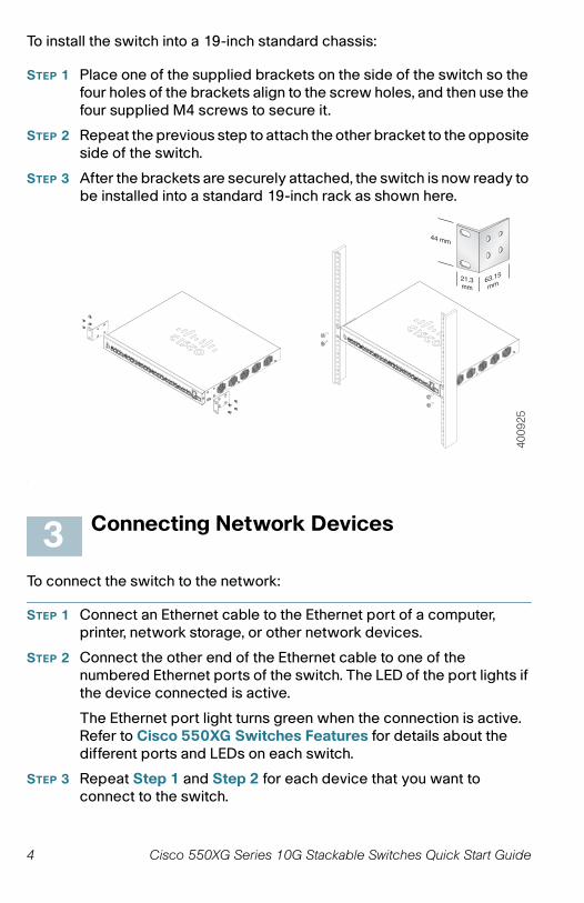
To install the switch into a 19-inch standard chassis:
STEP 1 Place one of the supplied brackets on the side of the switch so the four holes of the brackets align to the screw holes, and then use the four supplied M4 screws to secure it.
STEP 2 Repeat the previous step to attach the other bracket to the opposite side of the switch.
STEP 3 After the brackets are securely attached, the switch is now ready to be installed into a standard 19-inch rack as shown here.
Connecting Network Devices
To connect the switch to the network:
STEP 1 Connect an Ethernet cable to the Ethernet port of a computer, printer, network storage, or other network devices.
STEP 2 Connect the other end of the Ethernet cable to one of the numbered Ethernet ports of the switch. The LED of the port lights if the device connected is active.
The Ethernet port light turns green when the connection is active. Refer to Cisco 550XG Switches Features for details about the different ports and LEDs on each switch.
STEP 3 Repeat Step 1 and Step 2 for each device that you want to connect to the switch.
4009
25
3
4 Cisco 550XG Series 10G Stackable Switches Quick Start Guide
NOTE We strongly recommend using Cat6A or better cable to connect network devices. When you connect your network devices, do not exceed the maximum cabling distance of 100 meters (328 feet). It can take up to one minute for attached devices or the LAN to be operational after it is connected. This is normal behavior.
Configuring the Cisco 550XG Switches
Before You Begin
The switch can be accessed and managed by two different methods; over your IP network using the web-based interface, or by using the switch’s command-line interface through the console port. Using the console port requires advanced user skills.
These are the default settings used when configuring your switch for the first time.
Configuring Your Switch Using the Web-based Interface
To access the switch with a web-based interface, you must know the IP address that the switch is using. The default configuration of the switch is to use its factory default IP address of 192.168.1.254 by default.
When the switch is using the factory default IP address, the System LED flashes continuously. When the switch is using a DHCP server-assigned IP address or an administrator has configured a static IP address, the System LED is on solid (DHCP is enabled by default).
NOTE If you are managing the switch through a network connection and the switch IP address is changed, either by a DHCP server or manually, your access to the switch will be lost. You must enter the new IP address that the switch is using into your browser to use the web-based interface. If you are managing the switch through a console port connection, the link is retained.
Parameter Default Value
Username cisco
Password cisco
LAN IP 192.168.1.254
124
Cisco 550XG Series 10G Stackable Switches Quick Start Guide 5
To configure the switch using the web-based interface:
STEP 1 Power on the computer and your switch.
STEP 2 Connect the computer to the OOB port on the front panel of the switch.
STEP 3 Set up the IP configuration on your computer.
a. If the switch is using the default static IP address of 192.168.1.254, you must choose an IP address in the range of 192.168.1.2 to 192.168.1.253 that is not already in use.
b. If the IP addresses will be assigned by DHCP, make sure that your DHCP server is running and can be reached from the switch and the computer. You may need to disconnect and reconnect the devices for them to discover their new IP addresses from the DHCP server.
NOTE Details on how to change the IP address on your computer depend upon the type of architecture and operating system that you are using. Use your computers local Help and Support functionality and search for “IP Addressing.”
STEP 4 Open a web browser window. If you are prompted to install an Active-X plug-in when connecting to the device, follow the prompts to accept the plug-in.
STEP 5 Enter the switch IP address in the address bar and press Enter. For example, http://192.168.1.254.
STEP 6 When the login page appears, choose the language that you prefer to use in the web-based interface and enter the username and password.
The default username is cisco. The default password is cisco. Usernames and passwords are both case sensitive.
STEP 7 Click Log In.
If this is the first time that you have logged on with the default username and password, the Change Password page opens. The rules for constructing a new password are displayed on the page.
STEP 8 Enter a new password and confirm the password.
NOTE Password complexity is enabled by default. The password must comply with the default complexity rules or it can be disabled temporarily by checking Disable next to the Password Strength Enforcement option.
STEP 9 Click Apply.
6 Cisco 550XG Series 10G Stackable Switches Quick Start Guide

CAUTION Make sure that any configuration changes made are saved before exiting from the web-based interface by clicking on the Save icon. Exiting before you save your configuration will result in all changes being lost.
The Getting Started page opens. You are now ready to configure the switch. Refer to the Cisco 550XG Series 10G Stackable Managed Switches Administration Guide or see the help pages for further information.
Configuring Your Switch Using the Console Port
To configure the switch using the console port:
STEP 1 Connect a computer to the switch console port using the supplied console cable.
STEP 2 Start a console port utility such as HyperTerminal on the computer.
STEP 3 Configure the utility with the following parameters:
• 115200 bits per second
• 8 data bits
• no parity
• 1 stop bit
• no flow control
STEP 4 Enter a username and password. The default username is cisco, and the default password is cisco. Usernames and passwords are both case sensitive.
If this is the first time that you have logged on with the default username and password, the following message appears:
Please change your password from the default settings. Please change the password for better protection of your network. Do you want to change the password (Y/N) [Y]?
STEP 5 Enter Y, and set a new administrator password.
NOTE Password complexity is enabled by default. The password must comply with the default complexity rules.
Cisco 550XG Series 10G Stackable Switches Quick Start Guide 7
CAUTION Make sure that any configuration changes made are saved before exiting.
You are now ready to configure the switch. Refer to the Cisco 550XG Series 10G Stackable Managed Switches Command Line Interface Reference Guide for further information.
NOTE If you are not using DHCP on your network, set the IP address type on the switch to Static and change the static IP address and subnet mask to match your network topology. Failure to do so may result in multiple switches using the same factory default IP address of 192.168.1.254.
Stacking the Cisco 550XG Switches
Before configuring the switches as a stack, refer to the Cisco 550XG Series 10G Stackable Managed Switches Administration Guide for additional details. Refer to the front panel graphics in Cisco 550XG Switches Features to help with the stack port descriptions and supported modules.
By default the ports on a switch function as regular Ethernet ports except if you configure them to do stacking. You cannot mix the stack speeds between the switches or ports.
WARNING Stack ports must be either configured with the same port speed or have the same speed capability on the module or cable plug in. If the port speed is configured as auto, then the module plugged into these two ports will need to have the same speed capability, otherwise the switch will not be able to form as a stack with multiple units.
A stack can have up to eight 550XG series switches in it. Any port of the switch can be used for stacking. The switch can only be stacked with the Cisco 550 series switches without Mesh topology.
The switches in the same stack are connected together through their stack ports. Depending on the type of stack ports and the desired speed, you may need regular Cat6A or better Ethernet cables and/or Cisco approved modules or cables for the Cisco 550XG series switches.
8 Cisco 550XG Series 10G Stackable Switches Quick Start Guide
Cisco 550XG Switches Features
This section describes the available product models and the exterior of the switch to help familiarize you with your switch.
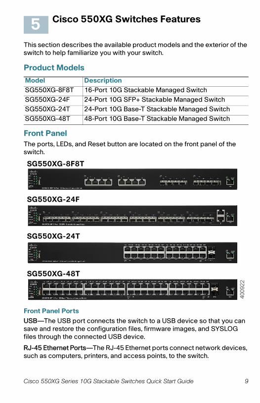
Product Models
Front Panel
The ports, LEDs, and Reset button are located on the front panel of the switch.
Front Panel Ports
USB—The USB port connects the switch to a USB device so that you can save and restore the configuration files, firmware images, and SYSLOG files through the connected USB device.
RJ-45 Ethernet Ports—The RJ-45 Ethernet ports connect network devices, such as computers, printers, and access points, to the switch.
Model Description
SG550XG-8F8T 16-Port 10G Stackable Managed Switch
SG550XG-24F 24-Port 10G SFP+ Stackable Managed Switch
SG550XG-24T 24-Port 10G Base-T Stackable Managed Switch
SG550XG-48T 48-Port 10G Base-T Stackable Managed Switch
5
SG550XG-8F8T
SG550XG-24F
SG550XG-24T
SG550XG-48T
4009
22
Cisco 550XG Series 10G Stackable Switches Quick Start Guide 9
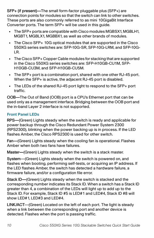
SFP+ (if present)—The small form-factor pluggable plus (SFP+) are connection points for modules so that the switch can link to other switches. These ports are also commonly referred to as mini 10GigaBit Interface Converter ports. The term SFP+ will be used in this guide.
• The SFP+ ports are compatible with Cisco modules MGBSX1, MGBLH1,�MGBT1, MGBLX1, MGBBX1, as well as other brands of modules.
• The Cisco SFP+ 10G optical modules that are supported in the Cisco 550XG series switches are: SFP-10G-SR, SFP-10G-LRM, and SFP-10G-LR.
• The Cisco SFP+ Copper Cable modules for stacking that are supported in the Cisco 550XG series switches are: SFP-H10GB-CU1M, SFP-H10GB-CU3M, and SFP-H10GB-CU5M.
• The SFP+ port is a combination port, shared with one other RJ-45 port. When the SFP+ is active, the adjacent RJ-45 port is disabled.
• The LEDs of the shared RJ-45 port light to respond to the SFP+ port traffic.
OOB—The Out of Band (OOB) port is a CPU's Ethernet port that can be used only as a management interface. Bridging between the OOB port and the in-band Layer 2 interface is not supported.
Front Panel LEDs
RPS—(Green) Lights steady when the switch is ready and applicable for power backup through the Cisco Redundant Power System 2300 (RPS2300), blinking when the power backing up is in process. If the LED flashes Amber, the Cisco RPS2300 is used for other switch.
Fan—(Green) Lights steady when the cooling fan is operational. Flashes Amber when both two fans have failures.
Master—(Green) Lights steady when the switch is a stack master.
System—(Green) Lights steady when the switch is powered on, and flashes when booting, performing self-tests, or acquiring an IP address. If the LED flashes Amber, the switch has detected a hardware failure, a firmware failure, and/or a configuration file error.
Stack ID—(Green) Lights steady when the switch is stacked and the corresponding number indicates its Stack ID. When a switch has a Stack ID greater than 4, a combination of the LEDs will light up to add up to the Stack ID. For example, Stack ID #5 is LED#1 and LED#4, Stack ID #8 will show LED#1, LED#3 and LED#4.
LINK/ACT—(Green) Located on the left of each port. The light is steady when a link between the corresponding port and another device is detected. Flashes when the port is passing traffic.
10 Cisco 550XG Series 10G Stackable Switches Quick Start Guide
XG—(Green) Located on the right of a 10G port. Lights steady when another device is connected to the port, is powered on, and a 10 Gbps link is established between the devices. When the LED is off, the connection speed is under 10 Gbps or nothing is cabled to the port.
Gigabit—(Green) Located on the right of the OOB port. Lights steady when another device is connected to the port, is powered on, and a1000 Mbps link is established between the devices. When the LED is off, the connection speed is under 1000 Mbps or nothing is cabled to the port.
SFP+ (if present)—(Green) Located on the right of a 10G port. Lights steady when a connection is made through the shared port. Flashes when the port is passing traffic.
Reset Button
The switch can be reset by inserting a pin or paper clip into the Reset button opening on the front panel of the switch. See Returning the Cisco 550XG Switches to the Factory Default Settings for details.
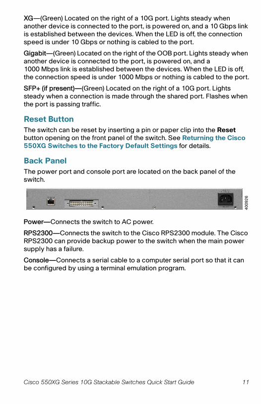
Back Panel
The power port and console port are located on the back panel of the switch.
Power—Connects the switch to AC power.
RPS2300—Connects the switch to the Cisco RPS2300 module. The Cisco RPS2300 can provide backup power to the switch when the main power supply has a failure.
Console—Connects a serial cable to a computer serial port so that it can be configured by using a terminal emulation program.
40
09
26
Cisco 550XG Series 10G Stackable Switches Quick Start Guide 11
Returning the Cisco 550XG Switches to the Factory Default Settings
To use the Reset button to reboot or reset the switch, do the following:
• To reboot the switch, press and hold the Reset button for less than ten seconds.
• To restore the switch to its factory default settings:
– Disconnect the switch from the network or disable all DHCP servers on your network.
– With the power on, press and hold the Reset button for more than ten seconds.
Troubleshoot Your Connection
If you cannot access your switch from the web-based interface, the switch may not be reachable from your computer. You can test network connections by using ping on a computer running Windows:
STEP 1 Open a command window by selecting Start > Run and enter cmd.
STEP 2 At the Command window prompt, enter ping and the switch IP address. For example, ping 192.168.1.254 (the default static IP address of the switch).
If you can reach the switch, you should get a reply similar to the following:
Pinging 192.168.1.254 with 32 bytes of data:Reply from 192.168.1.254:bytes=32 time<1ms TTL=128
If you cannot reach the switch, you should get a reply similar to the following:
Pinging 192.168.1.254 with 32 bytes of data:Request timed out.
Possible Causes and Resolutions
No Power:
Power up the switch and your computer if they are turned off.
Bad Ethernet connection:
Check the LEDs for proper indications. Check the connectors of the Ethernet cable to ensure that they are firmly plugged into the switch and your computer.
6
12 Cisco 550XG Series 10G Stackable Switches Quick Start Guide
Bad Console port connection:
Check the console cable connectors to make sure that they are firmly plugged into the switch and your computer. Make sure that the console port utility is configured with the correct parameters.
Wrong IP address:
Make sure that you are using the correct IP address of the switch. You can determine the current IP address of the switch from the CLI through the console port, or from your network administrator. The System LED provides an indication of where the switch received the IP address (See Front Panel for details.) Make sure that no other device is using the same IP address as the switch.
No IP route:
If the switch and your computer are in different IP subnets, you need one or more routers to route the packets between the two subnets.
Unusually long access time:
Due to the standard spanning tree loop detection logic, adding new connections may take 30 to 60 seconds for the affected interfaces and/or LAN to become operational.
Cisco 550XG Series 10G Stackable Switches Quick Start Guide 13
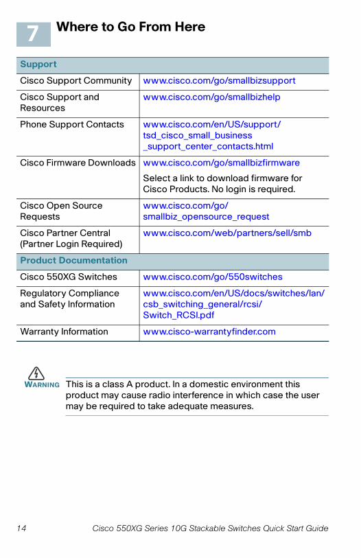
Where to Go From Here
WARNING This is a class A product. In a domestic environment this product may cause radio interference in which case the user may be required to take adequate measures.
Support
Cisco Support Community www.cisco.com/go/smallbizsupport
Cisco Support and Resources
www.cisco.com/go/smallbizhelp
Phone Support Contacts www.cisco.com/en/US/support/tsd_cisco_small_business _support_center_contacts.html
Cisco Firmware Downloads www.cisco.com/go/smallbizfirmware
Select a link to download firmware for Cisco Products. No login is required.
Cisco Open Source Requests
www.cisco.com/go/smallbiz_opensource_request
Cisco Partner Central (Partner Login Required)
www.cisco.com/web/partners/sell/smb
Product Documentation
Cisco 550XG Switches www.cisco.com/go/550switches
Regulatory Compliance and Safety Information
www.cisco.com/en/US/docs/switches/lan/csb_switching_general/rcsi/Switch_RCSI.pdf
Warranty Information www.cisco-warrantyfinder.com
7
14 Cisco 550XG Series 10G Stackable Switches Quick Start Guide
Cisco 550XG Series 10G Stackable Switches Quick Start Guide 15
Americas Headquarters
Cisco Systems, Inc.www.cisco.com
Cisco has more than 200 offices worldwide. Addresses, phone numbers, and fax numbersare listed on the Cisco website atwww.cisco.com/go/offices.
Cisco and the Cisco logo are trademarks or registered trademarks of Cisco and/or its affiliates
in the U.S. and other countries. To view a list of Cisco trademarks, go to this URL:www.cisco.com/go/trademarks. Third-party trademarks mentioned are the property of their
respective owners. The use of the word partner does not imply a partnership relationship
between Cisco and any other company. (1110R)
© 2015 Cisco Systems, Inc. All rights reserved.
78-100649-01