Embed Size (px)
Citation preview

Quick Start Guide
MP1590BNetwork Performance Tester EoS Measurement
EoS測定クイックスタートガイド

CONFIDE
NTIAL 1
Copyright � 2005 by ANRITSU CORPORATION The contents of this manual shall not be disclosed in any way or reproduced in any media without the express written permission of Anritsu Corporation.

1 / 45
MP1590B Network Performance TesterMP1590B Network Performance TesterEoS Measurement Quick Start GuideEoS Measurement Quick Start Guide
Anritsu CorporationIP Network Div.
First edition
MBP-1SG050233-00
2 / 45
Before using MP1590BBefore using MP1590B
Requisite task before measuringPut in “Key” and “Remote interlock” at the following circle.And turn on the key.In the case of “OFF”, MP1590B cannot transmitted an optical signal.
1

3 / 45
EoS Measurement FlowEoS Measurement Flow
EoS Measurement Flow1. Setup2. Port Setting (Mapping, Type, Bitrate and so on.)3. Connecting4. Setting concatenation5. Measurement
LCAS TestSDH/SONET TestVCAT test with Differential DelayEoS Frame test
6. Other functionsSave/LoadPrinting and Screen CopySwitching between SDH and SONET
4 / 45
Put MP1590B on a safe and stable place where MP1590B is not fallen down on.
A cooling fan is situated on the rear panel of the MP1590B. Place the MP1590B 10 cm or more apart from obstructions such as walls.
Supply power within voltage range of 100 to 115 Vac or 220 to 240 Vac and frequency range of 47.5 to 63 Hz. Power consumption is 500 Vac or less.
> 10cm
1. 1. Setup Setup -- setupsetup
2

5 / 45
MP1590B has two power switches,“Main power switch” and “Power switch for stand-by condition”.
The case of turning on the power(1) Connect a power code after ensuring that main power switch is Off.(2) Turn On the main power switch.(2’) From the Standby condition to power ON, press the power switch for
stand-by condition.The case of turning off the power
(1) Press the power switch for stand-by condition.(2) Turn off the main power switch.
Power Switch for Stand-by conditionMain Power Switch
1. 1. Setup Setup -- PowerPower--On/Off proceduresOn/Off procedures
6 / 45
1. 1. Setup Setup -- Selection of Measuring modeSelection of Measuring mode
Select the mode of application before measuring.SDH/SONET/OTN mode is chosen here.
SDH/SONET/OTN mode:For measuring SDH/SONET/OTN, Jitter.This mode does not support “VCAT” and “LCAS”
EoS mode:For measuring EoS, VCAT, LCAS.
SDH/SONET/OTN mode EoS mode
Button of changing mode
3

7 / 45
(2) Choose bit rate, encapsulation (mapping), and concatenation type
Choose the following parameters in pull down menue:
• Bit rate• Encapsulation (Mapping)• Concatenation
2. 2. Port setting (1)Port setting (1)
Choose bit rate, encapsulation (mapping), and concatenation type
(1) Open Port Setting screen Right-click the port icon and choose “Port Setting…” command.
To use the LCAS functions, check this box.
8 / 45
(4)GFP Initial settingWhen GFP setting is required, set
• Scramble ON/OFF• Ethernet Address of this port• Extension Header parameters• GFP FCS parameter of Rx side
according to the DUT conditions.This field changes according to the selected encapsulation (mapping).
This field is used when it connects to a DUT requires IP address like router, switch and so on.
(3) Choose measurement mode and clock modes(Measurement modes)Normal mode -- Supports transmitting / receiving data. Select for two-way connection.Through mode -- Transparent, OH Overwrite and Differential delay are also supported.Monitor mode -- Not usually used
2. 2. Port setting (2)Port setting (2)
4
9 / 45
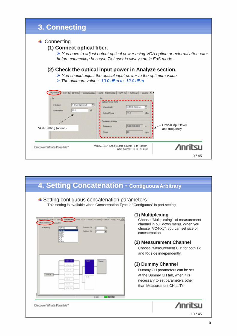
VOA Setting (option)Optical input leveland frequency
3. 3. ConnectingConnecting
Connecting(1) Connect optical fiber.
You have to adjust output optical power using VOA option or external attenuator before connecting because Tx Laser is always on in EoS mode.
(2) Check the optical input power in Analyze section.You should adjust the optical input power to the optimum value.The optimum value : -10.0 dBm to -12.0 dBm
MU150101A Spec. output power: -1 to +3dBminput power: -8 to -29 dBm
10 / 45
4. 4. Setting Concatenation Setting Concatenation -- Contiguous/ArbitraryContiguous/Arbitrary
Setting contiguous concatenation parametersThis setting is available when Concatenation Type is “Contiguous” in port setting.
(1) MultiplexingChoose “Multiplexing” of measurement channel in pull down menu. When you choose “VC4-Xc”, you can set size of concatenation.
(2) Measurement ChannelChoose “Measurement CH” for both Tx and Rx side independently.
(3) Dummy ChannelDummy CH parameters can be set at the Dummy CH tab, when it is necessary to set parameters other than Measurement CH at Tx.
5

11 / 45
Setting virtual concatenation parametersThis setting is available when Concatenation Type is “Virtual” in port setting.
(1) Setting Rx-side VCAT groupAt first, it has to match a concatenation and VCAT group with DUT’s one.Click “Edit…” button, to set VCG at Rx side.
4. 4. Setting Concatenation Setting Concatenation -- Virtual (1)Virtual (1)
(2) Setting MultiplexingNext, it has to choose “Multiplexing”. It also has to choose “Route” when it use Low Order Concatenation.
HO-VCAT LO-VCAT
12 / 45
(3) Detect VCG setting of DUT automaticallyClick the “Detect VCG…” button in the Rx VCAT Group Setting screen to show the detectedVCAT group in the Detect VCG screen.After analyzing, the result screen is appeared. Choose measurement VCG from list window.And click “OK” button for both Detect VCG and Rx Multiplexing screen.
4. 4. Setting Concatenation Setting Concatenation -- Virtual (2)Virtual (2)
If Rx signal includes some VCG, all VCG list up in this window.
6

13 / 45
(4-1) Copy Rx setting to Tx sideClick the “Copy from Rx Setting” button to copy Rx setting into Tx side.
4. 4. Setting Concatenation Setting Concatenation -- Virtual (3)Virtual (3)
If a VCG setting in Tx is the same as Rx’s one, see the (4-1);If a VCG setting is independent between Tx and Rx, see the (4-2);
Finish to set concatenation, see (5);Finish to set concatenation, see (5);
14 / 45
Multiplexing:At first, choose “multiplexing” from pull down menu. If it set VC3, VC12 or VC11, it also choose “Route” from AU4 or AU3.
Choose VCG size and Provisioned size automatically:VCG members and Provisioned channels can be picked up automatically when it set in this area. When it chooses manually, set VCG size to 0 and use the “VCG members”area.
(4-2) Tx-side VCG setting manuallyClick the “Edit…” button to open Tx Multiplexing screen.
4. 4. Setting Concatenation Setting Concatenation -- Virtual (4)Virtual (4)
HO-VCAT LO-VCAT
7

15 / 45
Choose VCG members and Provisioned channels manually:
Click “Add/Remove mode”. And choose channel from this area. A channel becomes VCG member by “Single Click”and becomes Provisioned channel by “Double Click”.
4. 4. Setting Concatenation Setting Concatenation -- Virtual (5)Virtual (5)
HO-VCAT LO-VCAT
Finish to set concatenation, see (5);Finish to set concatenation, see (5);
It is possible to change SQ for each channel in “SQ Setting mode”.
It is possible to choose channel across any AUG by this TAB in LO-VCAT.
16 / 45
(5) Check LinkupWhen it completes to set concatenation for both Tx and Rx side, the port icon becomes green from red. And any alarm/error have gone.
4. 4. Setting Concatenation Setting Concatenation -- Virtual (6)Virtual (6)
Linkup
If an error/alarm occurs, please check counter to get detail information,see 5-(4-1);
8

17 / 45
Choose VCG members and Provisioned channels manually:
Click “Add/Remove mode”. And choose channel from this area. A channel becomes VCG member by “Single Click”and becomes Provisioned channel by “Double Click”.
4. 4. Setting Concatenation Setting Concatenation -- Virtual (5)Virtual (5)
HO-VCAT LO-VCAT
Finish to set concatenation, see section 5 Measurement;Finish to set concatenation, see section 5 Measurement;
It is possible to change SQ for each channel in “SQ Setting mode”.
It is possible to choose channel across any AUG by this TAB in LO-VCAT.
18 / 45
(1) Setting LCASBefore starting LCAS negotiation, it has to set some conditions of LCAS measurement . Click “LCAS setting” button to open LCAS setting screen.
5.5. Measurement Measurement -- LCAS test (1)LCAS test (1)
(2) Set measurement scopeNext, choose a measurement scope.It recommends “VCG” because you get information of all VCG member in this setting.
Setting LCAS
9

19 / 45
(3) Set Tx CTRL ValueChoose a Tx CTRL Value.It recommends “---> DNU” because LCAS equipment also become “DNU” when it receive MST-Fail.
5.5. Measurement Measurement -- LCAS test (2)LCAS test (2)
(4) Negotiation ONCheck this box to start LCAS negotiation.
20 / 45
(5) Check a current LCAS statusIt is possible to check a summary of LCAS condition for both Source and Sink side like channel, SQ, MST, CTRL and so on in real time. Before change add/remove channel, you should confirm a current status of LCAS. You can also get a status of each channel as graphic in Status mode.
5.5. Measurement Measurement -- LCAS test (3)LCAS test (3)
If you need GID, Rs-Ack and Invert information, use monitor screen.
10
21 / 45
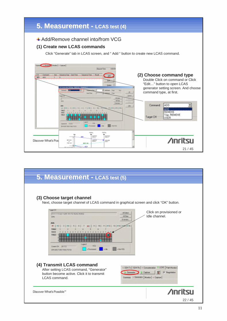
(1) Create new LCAS commandsClick “Generate” tab in LCAS screen, and “ Add “ button to create new LCAS command.
Add/Remove channel into/from VCG
(2) Choose command typeDouble Click on command or Click “Edit…” button to open LCAS generator setting screen. And choose command type, at first.
5.5. Measurement Measurement -- LCAS test (4)LCAS test (4)
22 / 45
(3) Choose target channelNext, choose target channel of LCAS command in graphical screen and click “OK” button.
5.5. Measurement Measurement -- LCAS test (5)LCAS test (5)
Click on provisioned or Idle channel.
(4) Transmit LCAS commandAfter setting LCAS command, “Generator”button become active. Click it to transmit LCAS command.
11

23 / 45
(5) Check a result of LCAS commandThe result of LCAS command is shown in result field with “Sequence Time”. After LCAS command complete, also check the result in “Summary” screen or DUT side.
Check or clear the checkbox for each command. Various pattern tests can be executed simply by changing the combination of checked checkboxes.
Application - Sending multiple LCAS send commandsUp to 64 LCAS send commands can be registered at the Generator tab.
5.5. Measurement Measurement -- LCAS test (6)LCAS test (6)
24 / 45
Capture LCAS command(1) Create LCAS send command
Before capture, set the capture parameters. The following is recommend parameters.
Set captured channel
Select trigger parameter
Set triggered channel
Set the position of triggered sequence. For example, when 3 is set, the triggered sequence is displayed third row and the condition before triggering is displayed in first and second row.
5.5. Measurement Measurement -- LCAS test (7)LCAS test (7)
Capture CH: Added or Removed channelTrigger
Change:CTRLTrigger Added or Removed channelTrigger Position:3
12

25 / 45
(2) Starting captureClick the “Capture” button to start capture.
After LCAS sequence complete, click“Capture” button again to stop capture. The captured sequences are displayed like this picture.
(3) Checking capture result
5.5. Measurement Measurement -- LCAS test (8)LCAS test (8)
26 / 45
Part 2 - VCAT counter functionThe VCAT counter counts B3 errors of each
VCG member.
(1) Checking SDH/SONET frame statusMP1590B has 3 way to check status of SDH/SONET. Click “Counter” button, then 2 counters are started. One is “counter”, other is VCAT counter. And the other way is Path Monitor, it always works.
5.5. Measurement Measurement -- SDH/SONET test (1)SDH/SONET test (1)
Checking SDH/SONET frame status of VCG
Part 1 - Counter functionThe counter function counts a lot of item from
SDH/SONET(1.5) layer to TCP/UDP(4) layer. It count total number of all VCG members.
13

27 / 45
5.5. Measurement Measurement -- SDH/SONET test (2)SDH/SONET test (2)
Part 3 - Path MonitorThe Path Monitor is able to count the detail status of each VCG members.
This field displays SDH/SONET, VCAT and LCAS status of the selected channel.This field displays VCAT, EoS and
Ethernet/IP status of VCG.
This field is Quick View. It is possible to display a history of status when it check “History” box.
28 / 45
(1) Inserting errors/alarmsWhen it inserts an error/alarm in SDH/SONET layer, Click “SDH Tx” Tab and “Alarm Error” tab. It is possible to choose error/alarm in pull down menu. Moreover, it is also possible to choose some inserting channels freely.
5.5. Measurement Measurement -- SDH/SONET test (3)SDH/SONET test (3)
Insert an error/alarm in SDH/SONET layer
Click on target channel
14
29 / 45
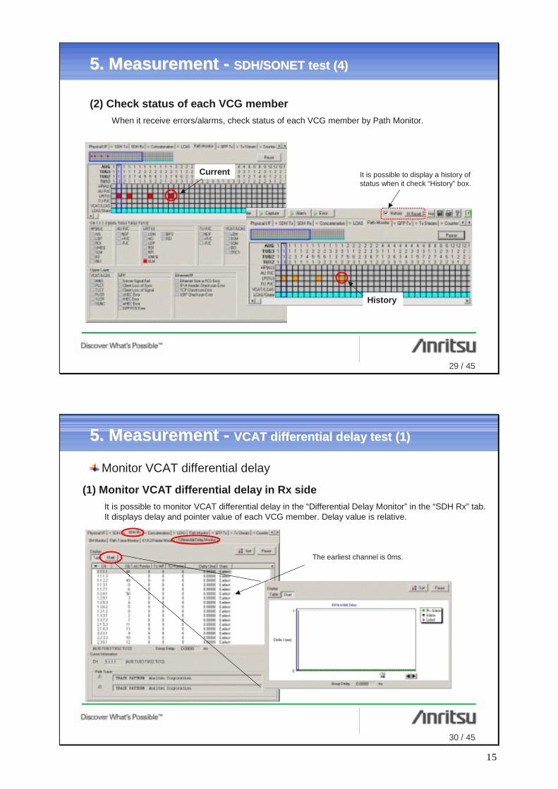
(2) Check status of each VCG memberWhen it receive errors/alarms, check status of each VCG member by Path Monitor.
5.5. Measurement Measurement -- SDH/SONET test (4)SDH/SONET test (4)
It is possible to display a history of status when it check “History” box.
History
Current
30 / 45
(1) Monitor VCAT differential delay in Rx sideIt is possible to monitor VCAT differential delay in the “Differential Delay Monitor” in the “SDH Rx” tab. It displays delay and pointer value of each VCG member. Delay value is relative.
5.5. Measurement Measurement -- VCAT differential delay test (1)VCAT differential delay test (1)
Monitor VCAT differential delay
The earliest channel is 0ms.
15
31 / 45
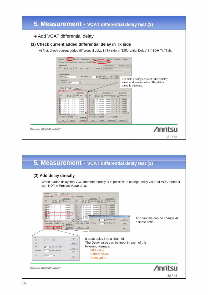
(1) Check current added differential delay in Tx sideAt first, check current added differential delay in Tx side in “Differential Delay” in “SDH Tx” Tab.
5.5. Measurement Measurement -- VCAT differential delay test (2)VCAT differential delay test (2)
Add VCAT differential delay
The field displays current added delay value and pointer value. This delay value is absolute.
32 / 45
(2) Add delay directlyWhen it adds delay into VCG member directly, it is possible to change delay value of VCG member with NDF in Present Value area.
5.5. Measurement Measurement -- VCAT differential delay test (3)VCAT differential delay test (3)
It adds delay into a channel. The Delay value can be input in each of the following formats.
MFI valuePointer valueDelta value
All channels can be change at a same time.
16

33 / 45
(3) Set a way of adding differential delay for Sweep modeIt is possible to add delay gradually by Sweep mode. Set a way of adding differential delay as Pointer Justification by “Order” and “Transition”.
5.5. Measurement Measurement -- VCAT differential delay test (4)VCAT differential delay test (4)
Step: Changes each Channel in turnSimultaneous: Changes each Channel simultaneously
Present0 ms
Target A256 ms
Target B0 ms
Repetition
(1)(2)
(3)
- Example -
34 / 45
5.5. Measurement Measurement -- VCAT differential delay test (5)VCAT differential delay test (5)
Check on target channels
(4) Set delay valueSet target channels and target value for Sweep mode.
(5) Add differential delay in Sweep modeClick “Sweep” button to add delay gradually.
Target A Target B
17

35 / 45
5.5. Measurement Measurement -- VCAT differential delay test (6)VCAT differential delay test (6)
(6) Monitor VCAT differential delay in Rx side againMeasurement example
(7) differential delay with Through modeWhen it adds delay in Through mode, it set through mode in “Port Setting” and check “differential delay”.
36 / 45
(1) Create Tx streamSelect the Tx Stream tab and fetch the Tx Data Setting screen. Click the Add button to register a new Tx stream. The transmitted data contents MAC/IP address, transmitted load, transmitted data repetition pattern are defined in the Tx stream. Up to 256 streams can be registered.
Setting GFP frame as EoS transmitting data-This setup is enabled when the port mapping setting is Frame mapped GFP.
Tx stream
The GFP Tx tab contains settings required for the ARP and Ping auto-reply function. When using neither the ARP nor Ping functions, these settings are not required.
5.5. Measurement Measurement -- EoS test (1)EoS test (1)
18

37 / 45
(2) Setting Tx stream transmission methodDouble-click the Tx stream or click the “Edit…” button to set the Tx stream control and Tx stream repetition pattern at the Stream Control tab of the Tx Stream Edit screen.
When sending with a fixed load, select Continuous at the Distribution menu (transmits set frame continuously).
When Continuous is set, the load setting is set at Frame Gap. The various units for the Inter Frame Gap are set at the Unit menu.
Select % and input the value as 100% . (100% is Full wire rate of total bandwidth of provisioned channel.)
5.5. Measurement Measurement -- EoS test (2)EoS test (2)
38 / 45
(3) Setting frame dataThe Tx data contents (protocol, MAC/IP address, etc.) are set at the Frame Setting tab at the Tx Stream Edit screen.
First, select the protocol. Select None when using only GFP frames, or Ethernet when using GFP+Ethernet frames. Ethernet is selected in this example. The contents of higher-level tabs change according to the selected protocol..
GFP-related data (FCS, Extension Header, etc) is set at the GFP tab.
Ethernet-related data (MAC Address, Ethernet Type, etc.) is set at the Ethernet tab.
5.5. Measurement Measurement -- EoS test (3)EoS test (3)
GFP FCS parameter of Tx side
19

39 / 45
(5) Starting Tx stream transmissionAfter completing the settings, click the “OK” buttonandclick the “Transmit” button to transmit the Tx stream. During sending, a small arrow icon (->) is displayed on the Port icon. In the example on the right, receiving is also being checked simultaneously, so a double-ended arrow (<->) is displayed.
(4) Inserting error framesWhen it is necessary to set error frames, select the Error Insertion tab. Error frames can be set independently for each GFP, Ethernet, IP, TCP/UDP layer.
5.5. Measurement Measurement -- EoS test (4)EoS test (4)
40 / 45
Checking received stream after setting Tx stream
(1) Starting countingMove to the Counter tab and click the “Counter” (ON/OFF) button to start counting items such as:
Transmitted frame countReceived frame countError countetc.
Various information can be checked in real time.
Counter items become green (errors are red)
The counter items and their order can be set freely.
Filter condition button
5.5. Measurement Measurement -- EoS test (5)EoS test (5)
20

41 / 45
Capture function for checking actual EoS frame traffic
(1) Starting captureMove to the Capture tab and click the “Capture” (ON/OFF) button to start capture.Click the button again to stop capture.
(2) Displaying captured dataAfter capture, select the captured frames to be displayed on the screen.Click the Retrieve Capture Data button to display the Capture View screen and select the frame to be displayed.In this example, frames 1 to 1000 will be displayed.
It indicate number of captured EoS frames.
Trigger/Filter condition button
5.5. Measurement Measurement -- EoS test (6)EoS test (6)
42 / 45
(3) Analyzing EoS frameDisplayed frame are listed at the top of the screen. When a frame is selected, the details of the frame contents are displayed at the bottom part of the screen.When the Decode tab is clicked, it is possible to perform analysis of the displayed EoS frame (GFP in this example).
5.5. Measurement Measurement -- EoS test (7)EoS test (7)
21
43 / 45
6. 6. Others Others -- Save/LoadSave/Load
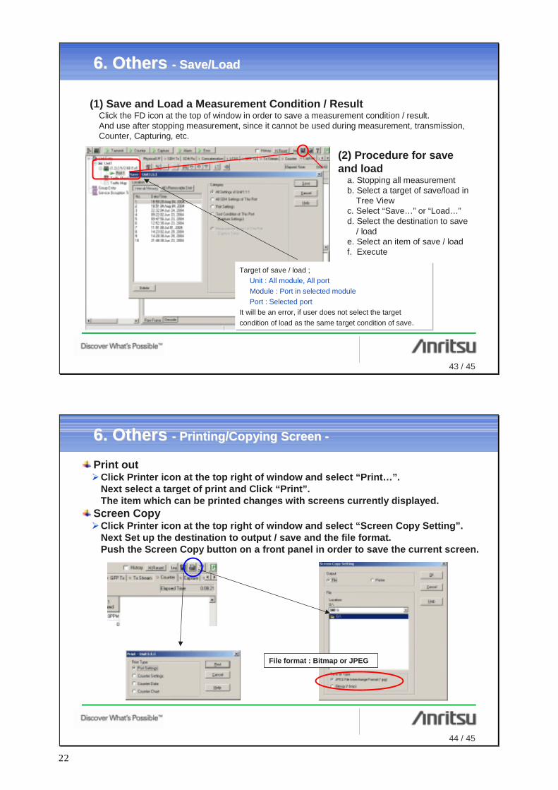
(1) Save and Load a Measurement Condition / ResultClick the FD icon at the top of window in order to save a measurement condition / result. And use after stopping measurement, since it cannot be used during measurement, transmission, Counter, Capturing, etc.
(2) Procedure for save and load
a. Stopping all measurementb. Select a target of save/load in
Tree Viewc. Select “Save…” or “Load…”d. Select the destination to save
/ loade. Select an item of save / loadf. Execute
Target of save / load ;Unit : All module, All portModule : Port in selected modulePort : Selected port
It will be an error, if user does not select the target condition of load as the same target condition of save.
Target of save / load ;Unit : All module, All portModule : Port in selected modulePort : Selected port
It will be an error, if user does not select the target condition of load as the same target condition of save.
44 / 45
6. 6. Others Others -- Printing/Copying Screen Printing/Copying Screen --
Print outClick Printer icon at the top right of window and select “Print…”. Next select a target of print and Click “Print”.The item which can be printed changes with screens currently displayed.
Screen CopyClick Printer icon at the top right of window and select “Screen Copy Setting”. Next Set up the destination to output / save and the file format.Push the Screen Copy button on a front panel in order to save the current screen.
File format : Bitmap or JPEG
22

45 / 45
6. 6. Others Others -- Changing SDH/SONETChanging SDH/SONET
• It is possible to change SDH/SONET in GUI Setting window.Click “Unit” in Tree view by the right button, and select “GUI Setting…”in dropped menu.Select SDH view / SONET view at “Standard” in pop-up window,and click “OK”.
Right clickRight click
Changing SDH/SONET
Changing Linear/Ring
23

Confidential
No.MP1590B_EoS-E-F-1-(2.00) Printed in Japan 2005-9 AKD
MP
1590
B E
oS M
easu
rem
ent Q
uick
Sta
rt G
uide
AP
PLI
CA
TIO
N N
OT
E
ANRITSU CORPORATION1800 Onna, Atsugi-shi, Kanagawa, 243-8555 JapanPhone: +81-46-223-1111Fax: +81-46-296-1264
• U.S.A.ANRITSU COMPANYTX OFFICE SALES AND SERVICE1155 East Collins Blvd., Richardson, TX 75081, U.S.A.Toll Free: 1-800-ANRITSU (267-4878)Phone: +1-972-644-1777Fax: +1-972-644-3416
• CanadaANRITSU ELECTRONICS LTD.700 Silver Seven Road, Suite 120, Kanata, ON K2V 1C3, CanadaPhone: +1-613-591-2003 Fax: +1-613-591-1006
• Brasil ANRITSU ELETRÔNICA LTDA.Praca Amadeu Amaral, 27 - 1 andar01327-010 - Paraiso, Sao Paulo, BrazilPhone: +55-11-3283-2511Fax: +55-11-3886940
• U.K.ANRITSU LTD.200 Capability Green, Luton, Bedfordshire LU1 3LU, U.K.Phone: +44-1582-433280 Fax: +44-1582-731303
• GermanyANRITSU GmbHNemetschek Haus Konrad-Zuse-Platz 1 81829München, Germany Phone: +49 (0) 89 442308-0 Fax: +49 (0) 89 442308-55
• FranceANRITSU S.A.9, Avenue du Québec Z.A. de Courtabœuf 91951 LesUlis Cedex, France Phone: +33-1-60-92-15-50Fax: +33-1-64-46-10-65
• ItalyANRITSU S.p.A.Via Elio Vittorini, 129, 00144 Roma EUR, ItalyPhone: +39-06-509-9711 Fax: +39-06-502-2425
• SwedenANRITSU ABBorgafjordsgatan 13 164 40 Kista, SwedenPhone: +46-853470700 Fax: +46-853470730
• FinlandANRITSU ABTeknobulevardi 3-5, FI-01530 Vantaa, FinlandPhone: +358-9-4355-220Fax: +358-9-4355-2250
• DenmarkAnritsu AB DanmarkKorskildelund 6 DK - 2670 Greve, DenmarkPhone: +45-36915035Fax: +45-43909371
• SingaporeANRITSU PTE LTD.10, Hoe Chiang Road #07-01/02, Keppel Towers,Singapore 089315 Phone: +65-6282-2400 Fax: +65-6282-2533
• Hong Kong ANRITSU COMPANY LTD.Suite 923, 9/F., Chinachem Golden Plaza, 77 ModyRoad, Tsimshatsui East, Kowloon, Hong Kong, ChinaPhone: +852-2301-4980Fax: +852-2301-3545
• P. R. ChinaANRITSU COMPANY LTD.Beijing Representative OfficeRoom 1515, Beijing Fortune Building, No. 5 NorthRoad, the East 3rd Ring Road, Chao-Yang DistrictBeijing 100004, P.R. ChinaPhone: +86-10-6590-9230
• KoreaANRITSU CORPORATION8F Hyun Juk Bldg. 832-41, Yeoksam-dong, Kangnam-ku, Seoul, 135-080, KoreaPhone: +82-2-553-6603Fax: +82-2-553-6604
• AustraliaANRITSU PTY LTD.Unit 3/170 Forster Road Mt. Waverley, Victoria, 3149,AustraliaPhone: +61-3-9558-8177Fax: +61-3-9558-8255
• TaiwanANRITSU COMPANY INC.7F, No. 316, Sec. 1, NeiHu Rd., Taipei, TaiwanPhone: +886-2-8751-1816Fax: +886-2-8751-1817
Specifications are subject to change without notice.
050912
Printed on 100% Recycled Paper


![Cesmac Pos Graduacao to Open Source Parte II [Vcg]](https://img.pdfslide.net/doc/110x75/577d2a051a28ab4e1ea87ef2/cesmac-pos-graduacao-to-open-source-parte-ii-vcg.jpg)