Embed Size (px)
Citation preview

Quick Start Motion Application Software - QS_AIS_1
SHEFFIELD AUTOMATION QUICK START MOTION APPLICATION SOFTWARE 1
Quick Start Motion Application Software – QS_AIS_1Quick Start Motion Application Software allows commissioning of 1 to 32 axes motionapplications in a matter of hours. Basic motion control is transformed from aprogramming effort to an application exercise.
The foundation of the Quick Start package is the basic motion control applicationspecific function block (ASFB). Two ASFB’s address basic motion control, these are:
• QS_AIS_1 – Basic servo motion control ASFB
• QS_DIG_1 – Master axis feedback interface ASFB
One ASFB provides fault control and fault history, this is:• QS_FLT_1 – Fault control and fault history ASFB
One ASFB provides integration with a Cimrex Operator Interface, this is:• QS_C69_1 – Integration with Cimrex C69 HMI operating in portrait mode
These functions may be used with PiC, MMC or MMC for PC controls.
This document covers the functionality provided by QS_AIS_1.
QS_AIS_1 Overview
QS_AIS_1 provides a single-network solution to basic servo motion providing DriveControl, Manual Operation and Homing. Functions provide by QS_AIS_1 include:
Drive Control, including:• Machine Start Logic
• Drive Enable and Reset Control
• Drive Ready Monitor
• Fault Detection and Status Reporting
Manual servo operation, including:• Velocity Jog – jog at a rate
• Incremental Jog – jog a distance at a rate
• Handwheel Jog – follow a handwheel (feedback device) at a ratio
Home cycle, including:• Home Reference Cycle
• Move to Park Position after Home Complete

Quick Start Motion Application Software - QS_AIS_1
2 QUICK START MOTION APPLICATION SOFTWARE SHEFFIELD AUTOMATION
Using QS_AIS_1 each axis is controlled by a single network in the main applicationprogram. Interface between your application and QS_AIS_1 using the Control DataStructures. Status Messages provide English-language status messages for all ofthe QS_AIS_1 operations. The Status outputs of QS_AIS_1 provide an overview ofaxis fault status. The Axis I/O Interface logic provides the interface between ControlData Structures and the I/O used for basic drive and motion control.
Control of the servo axis can be performed by additional application logic or operatorinterface manipulation of variables in the Control Data Structures.
The Control Data Structures include:
Structure Description FunctionSTAT Status Present Status InformationCTRL Control Control Drive OperationJOG Jog Jog, Incremental Jog and Handwheel Jog OperationHOME Home Home Cycle OperationFLNK Fault Link Coordinate fault control in multiple axis applications
The Status Messages provide:
Variable Description FunctionSMSG Status Description of operating status or fault if fault presentMMSG Motion Description of currently active move instructionJMSG Jog Description of Jog Operation stateHMSG Home Description of Home Cycle Operation state
Status MessagesAxis I/O Interface
Control Data Structures
Status
Quick Start Motion Application Software - QS_AIS_1
SHEFFIELD AUTOMATION QUICK START MOTION APPLICATION SOFTWARE 3
AXIS – Servo Axis Number
Axis specifies the servo axis number that this instance of QS_AIS_1 controls. Axisranges from 1 to 32 and is converted to the servo setup axis number, 1 to 16 for axis1 to 16 and 101 to 117 for axis 17 to 32, by QS_AIS_1. If Axis is out of range ERR,programming error will be 1007.
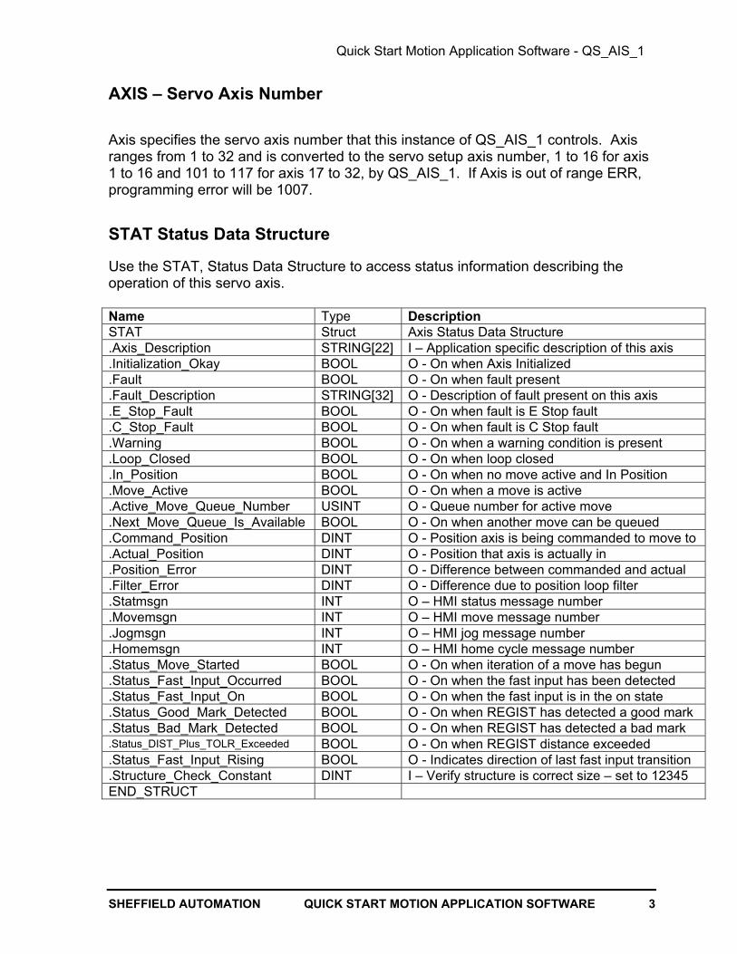
STAT Status Data Structure
Use the STAT, Status Data Structure to access status information describing theoperation of this servo axis.
Name Type DescriptionSTAT Struct Axis Status Data Structure.Axis_Description STRING[22] I – Application specific description of this axis .Initialization_Okay BOOL O - On when Axis Initialized.Fault BOOL O - On when fault present.Fault_Description STRING[32] O - Description of fault present on this axis.E_Stop_Fault BOOL O - On when fault is E Stop fault.C_Stop_Fault BOOL O - On when fault is C Stop fault.Warning BOOL O - On when a warning condition is present.Loop_Closed BOOL O - On when loop closed.In_Position BOOL O - On when no move active and In Position.Move_Active BOOL O - On when a move is active.Active_Move_Queue_Number USINT O - Queue number for active move.Next_Move_Queue_Is_Available BOOL O - On when another move can be queued.Command_Position DINT O - Position axis is being commanded to move to.Actual_Position DINT O - Position that axis is actually in.Position_Error DINT O - Difference between commanded and actual.Filter_Error DINT O - Difference due to position loop filter.Statmsgn INT O – HMI status message number.Movemsgn INT O – HMI move message number.Jogmsgn INT O – HMI jog message number.Homemsgn INT O – HMI home cycle message number.Status_Move_Started BOOL O - On when iteration of a move has begun.Status_Fast_Input_Occurred BOOL O - On when the fast input has been detected.Status_Fast_Input_On BOOL O - On when the fast input is in the on state.Status_Good_Mark_Detected BOOL O - On when REGIST has detected a good mark.Status_Bad_Mark_Detected BOOL O - On when REGIST has detected a bad mark.Status_DIST_Plus_TOLR_Exceeded BOOL O - On when REGIST distance exceeded.Status_Fast_Input_Rising BOOL O - Indicates direction of last fast input transition.Structure_Check_Constant DINT I – Verify structure is correct size – set to 12345END_STRUCT
Quick Start Motion Application Software - QS_AIS_1
4 QUICK START MOTION APPLICATION SOFTWARE SHEFFIELD AUTOMATION
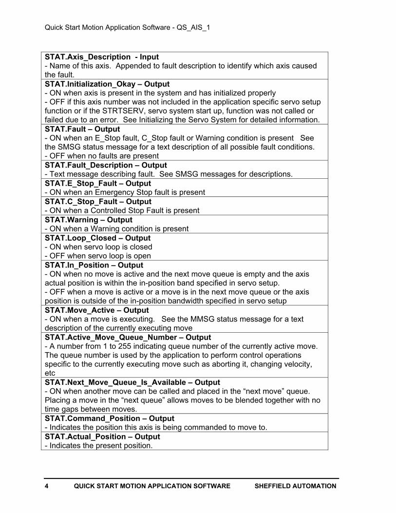
STAT.Axis_Description - Input- Name of this axis. Appended to fault description to identify which axis causedthe fault.STAT.Initialization_Okay – Output- ON when axis is present in the system and has initialized properly- OFF if this axis number was not included in the application specific servo setupfunction or if the STRTSERV, servo system start up, function was not called orfailed due to an error. See Initializing the Servo System for detailed information.STAT.Fault – Output- ON when an E_Stop fault, C_Stop fault or Warning condition is present Seethe SMSG status message for a text description of all possible fault conditions.- OFF when no faults are presentSTAT.Fault_Description – Output- Text message describing fault. See SMSG messages for descriptions.STAT.E_Stop_Fault – Output- ON when an Emergency Stop fault is presentSTAT.C_Stop_Fault – Output- ON when a Controlled Stop Fault is presentSTAT.Warning – Output- ON when a Warning condition is presentSTAT.Loop_Closed – Output- ON when servo loop is closed- OFF when servo loop is openSTAT.In_Position – Output- ON when no move is active and the next move queue is empty and the axisactual position is within the in-position band specified in servo setup.- OFF when a move is active or a move is in the next move queue or the axisposition is outside of the in-position bandwidth specified in servo setupSTAT.Move_Active – Output- ON when a move is executing. See the MMSG status message for a textdescription of the currently executing moveSTAT.Active_Move_Queue_Number – Output- A number from 1 to 255 indicating queue number of the currently active move.The queue number is used by the application to perform control operationsspecific to the currently executing move such as aborting it, changing velocity,etcSTAT.Next_Move_Queue_Is_Available – Output- ON when another move can be called and placed in the “next move” queue.Placing a move in the “next queue” allows moves to be blended together with notime gaps between moves.STAT.Command_Position – Output- Indicates the position this axis is being commanded to move to.STAT.Actual_Position – Output- Indicates the present position.

Quick Start Motion Application Software - QS_AIS_1
SHEFFIELD AUTOMATION QUICK START MOTION APPLICATION SOFTWARE 5
STAT.Position_Error – Output- Indicates the difference between the commanded position and the actualposition.STAT.Filter_Error – Output- Indicates the lag between the commanded position and the actual position dueto the slow velocity filterSTAT.Statmsgn – Output- Indicates the message number for HMI status message display. See the SMSG tablelater in this document for a list of all Status messages.STAT.Movemsgn – Output- Indicates the message number for HMI move message display. See the MMSG tablelater in this document for a list of all Status messages.STAT.Jogmsgn – Output- Indicates the message number for HMI jog operation message display. See the JMSGtable later in this document for a list of all Status messages.STAT.Homemsgn – Output- Indicates the message number for HMI home cycle message display. See the HMSGtable later in this document for a list of all Status messages.STAT.Status_Move_Started – Output- Indicates that the queued move has begun iterating. Use to see that move queuedwith FAST_QUE has been triggered and is executing. See STATUSSV function formore informationSTAT.Status_Fast_Input_Occurred – Output- Indicates that the Fast Input is in the ON state. See STATUSSV function for moreinformationSTAT.Status_Fast_Input_On – Output- Indicates that the Fast Input is in the ON state. See STATUSSV function for moreinformation.STAT.Status_Good_Mark_Detected – Output- Indicates that REGIST has detected a valid registration mark. See STATUSSV andREGIST functions for more informationSTAT.Status_Bad_Mark_Detected – Output- Indicates that REGIST has detected an invalid registration mark. See STATUSSV andREGIST functions for more informationSTAT.Status_DIST_Plus_TOLR_Exceeded – Output- Indicates that REGIST has seen the axis travel a distance in excess of DIST + TOLRsince the last good mark. See STATUSSV and REGIST functions for more informationSTAT.Status_Fast_Input_Rising – Output- Indicates the direction of the last fast input transition. See STATUSSV function formore information. See STATUSSV and REGIST functions for more informationSTAT.Structure_Check_Constant – Input- Must be set to an initial value of 12345. Checked by QS_AIS_1 on first scan, if not12345 then ERR will be set to 1001, ESTP will be energized, and QS_AIS_1 will exitwithout executing.
Quick Start Motion Application Software - QS_AIS_1
6 QUICK START MOTION APPLICATION SOFTWARE SHEFFIELD AUTOMATION
CTRL Control Data Stucture
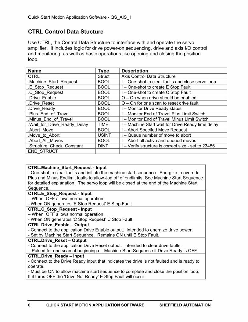
Use CTRL, the Control Data Structure to interface with and operate the servoamplifier. It includes logic for drive power-on sequencing, drive and axis I/O controland monitoring, as well as basic operations like opening and closing the positionloop.
Name Type DescriptionCTRL Struct Axis Control Data Structure.Machine_Start_Request BOOL I – One-shot to clear faults and close servo loop.E_Stop_Request BOOL I – One-shot to create E Stop Fault.C_Stop_Request BOOL I – One-shot to create C Stop Fault.Drive_Enable BOOL O – On when drive should be enabled.Drive_Reset BOOL O – On for one scan to reset drive fault.Drive_Ready BOOL I – Monitor Drive Ready status.Plus_End_of_Travel BOOL I – Monitor End of Travel Plus Limit Switch.Minus_End_of_Travel BOOL I – Monitor End of Travel Minus Limit Switch.Wait_for_Drive_Ready_Delay TIME I – Machine Start wait for Drive Ready time delay.Abort_Move BOOL I – Abort Specifed Move Request.Move_to_Abort USINT I – Queue number of move to abort.Abort_All_Moves BOOL I – Abort all active and queued moves.Structure_Check_Constant DINT I – Verify structure is correct size - set to 23456END_STRUCT
CTRL.Machine_Start_Request - Input- One-shot to clear faults and initiate the machine start sequence. Energize to overridePlus and Minus Endlimit faults to allow Jog off of endlimits. See Machine Start Sequencefor detailed explanation. The servo loop will be closed at the end of the Machine StartSequence.CTRL.E_Stop_Request - Input– When OFF allows normal operation- When ON generates ‘E Stop Request’ E Stop FaultCTRL.C_Stop_Request - Input– When OFF allows normal operation- When ON generates ‘C Stop Request’ C Stop FaultCTRL.Drive_Enable – Output- Connect to the application Drive Enable output. Intended to energize drive power.- Set by Machine Start Sequence. Remains ON until E Stop Fault. CTRL.Drive_Reset – Output- Connect to the application Drive Reset output. Intended to clear drive faults.– Pulsed for one scan at beginning of Machine Start Sequence if Drive Ready is OFF.CTRL.Drive_Ready – Input- Connect to the Drive Ready input that indicates the drive is not faulted and is ready tooperate.- Must be ON to allow machine start sequence to complete and close the position loop.If it turns OFF the ‘Drive Not Ready’ E Stop Fault will occur.
Quick Start Motion Application Software - QS_AIS_1
SHEFFIELD AUTOMATION QUICK START MOTION APPLICATION SOFTWARE 7
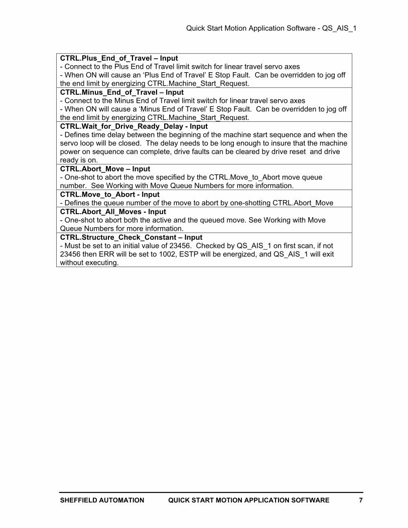
CTRL.Plus_End_of_Travel – Input- Connect to the Plus End of Travel limit switch for linear travel servo axes- When ON will cause an ‘Plus End of Travel’ E Stop Fault. Can be overridden to jog offthe end limit by energizing CTRL.Machine_Start_Request.CTRL.Minus_End_of_Travel – Input- Connect to the Minus End of Travel limit switch for linear travel servo axes- When ON will cause a ‘Minus End of Travel’ E Stop Fault. Can be overridden to jog offthe end limit by energizing CTRL.Machine_Start_Request.CTRL.Wait_for_Drive_Ready_Delay - Input- Defines time delay between the beginning of the machine start sequence and when theservo loop will be closed. The delay needs to be long enough to insure that the machinepower on sequence can complete, drive faults can be cleared by drive reset and driveready is on.CTRL.Abort_Move – Input- One-shot to abort the move specified by the CTRL.Move_to_Abort move queuenumber. See Working with Move Queue Numbers for more information. CTRL.Move_to_Abort - Input- Defines the queue number of the move to abort by one-shotting CTRL.Abort_MoveCTRL.Abort_All_Moves - Input- One-shot to abort both the active and the queued move. See Working with MoveQueue Numbers for more information.CTRL.Structure_Check_Constant – Input- Must be set to an initial value of 23456. Checked by QS_AIS_1 on first scan, if not23456 then ERR will be set to 1002, ESTP will be energized, and QS_AIS_1 will exitwithout executing.

Quick Start Motion Application Software - QS_AIS_1
8 QUICK START MOTION APPLICATION SOFTWARE SHEFFIELD AUTOMATION
JOG Data Structure
Use the JOG Data Structure to control of three modes of manual axis operation. JogPlus and Jog Minus provide manual jogging at an application specified rate, JogIncremental provides incremental distance moves using an application specified rateand distance and Handwheel Jog allows following a master axis (typically connectedto a Handwheel) at an application specified ratio.
Name Type DescriptionJOG Struct Axis Jog Control Data Structure.Plus BOOL I - Energize to Jog Plus.Minus BOOL I - Energize to Jog Minus.Rate UDINT I - Specify Jog Rate.Jog_Active BOOL O - On when Jog active.Incremental_Plus BOOL I - One-shot to start Incremental Jog Plus.Incremental_Minus BOOL I - One-shot to start Incremental Jog Minus.Incremental_Abort BOOL I - One-shot to abort Incremental Jog .Incremental_Rate DINT I - Specify Incremental Jog Move Rate.Incremental_Distance DINT I - Specify Incremental Jog Distance.Incremental_Jog_Active BOOL O - On when Incremental Jog active.Handwheel_Mode BOOL I - Energize to Enable Handwheel Jog Mode.Handwheel_Axis_Number USINT I - Specify Handwheel Jog Master Axis.Handwheel_Master_Distance DINT I - Specify Handwheel Jog Master Distance.Handwheel_Slave_Distance DINT I - Specify Handwheel Jog Slave Distance.Handwheel_Mode_Active BOOL O - On when Handwheel Jog Active.Structure_Check_Constant DINT I - Used to check structure size - set to 34567END_STRUCT
Jog.Plus – Input- Energize to move axis in plus direction at rate specified by JOG.Jog_Rate. IfCTRL.Plus_End_of_Travel is ON motion will not occur.- De-energize to stopJog.Minus – Input- Energize to move axis in minus direction at rate specified by JOG.Jog_Rate. IfCTRL.Minus_End_of_Travel is ON motion will not occur.- De-energize to stopJog.Rate – Input- Specify rate for Jog.Plus or Jog.MinusJog.Jog_Active – Output- ON when JOG.Plus or JOG.Minus operation is activeJog.Incremental_Plus – Input- One-shot to initiate incremental distance move in plus direction with distance specifiedby JOG.Incremental_Distance at the rate specified by JOG.Incremental_RateJog.Incremental_Minus – Input- One-shot to initiate incremental distance move in minus direction with distancespecified by JOG.Incremental_Distance at the rate specified by JOG.Incremental_RateJog. Incremental_Abort – Input- One-shot to abort a Jog Incremental Plus or Minus move before it completes.

Quick Start Motion Application Software - QS_AIS_1
SHEFFIELD AUTOMATION QUICK START MOTION APPLICATION SOFTWARE 9
Jog.Incremental_Rate – Input- Specifies the rate the Jog Incremental Plus or Minus move will be made at.Jog.Incremental_Distance – Input- Specifies the distance to be moved by Jog Incremental Plus or Minus movesJog.Incremental_Jog_Active – Output- ON when Jog Incremental Plus or Minus move is activeJog.Handwheel_Mode – Input- Energize to.select Handwheel Mode, De-energize to exit Handwheel ModeJog.Handwheel_Axis_Number – Input- Specify the digitized axis number that the Handwheel is interfaced to.Jog.Handwheel_Master_Distance – Input- Use with JOG.Handwheel_Slave_Distance to specify the ratio of handwheelmotion to axis motion. For example:
Handwheel to AxisJOG.Handwheel_Master_Distance JOG.Handwheel_Slave_Distance Ratio 1 1 1:1 10 1 10:1 100 500 1:5Jog.Handwheel_Slave_Distance – Input- Use with JOG.Handwheel_Master_Distance to specify the ratio of handwheel motion toaxis motion. See JOG.Handwheel_Master_Distance for explanation.Jog.Handwheel_Mode_Active – Output- ON when Jog Handwheel Mode is ActiveJog.Structure_Check_Constant – Input- Must be set to an initial value of 34567. Checked by QS_AIS_1 on first scan, if not34567 then ERR will be set to 1003, ESTP will be energized, and QS_AIS_1 will exitwithout executing.
Quick Start Motion Application Software - QS_AIS_1
10 QUICK START MOTION APPLICATION SOFTWARE SHEFFIELD AUTOMATION
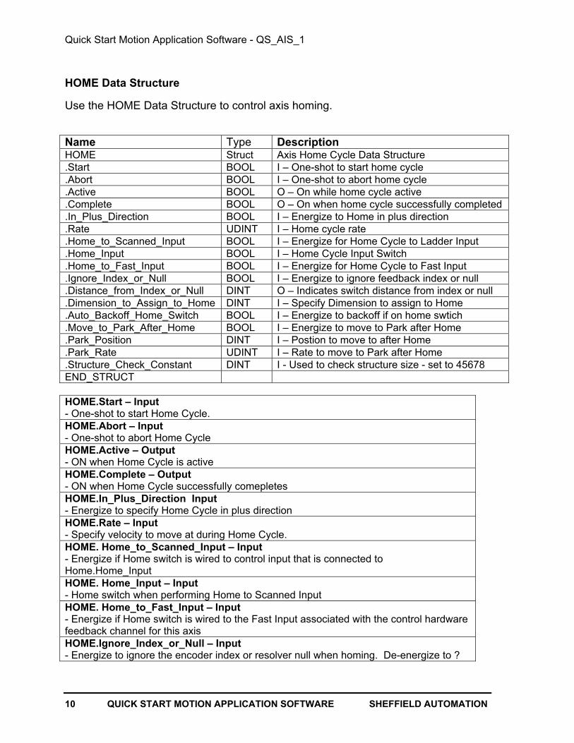
HOME Data Structure
Use the HOME Data Structure to control axis homing.
Name Type DescriptionHOME Struct Axis Home Cycle Data Structure.Start BOOL I – One-shot to start home cycle.Abort BOOL I – One-shot to abort home cycle.Active BOOL O – On while home cycle active.Complete BOOL O – On when home cycle successfully completed.In_Plus_Direction BOOL I – Energize to Home in plus direction.Rate UDINT I – Home cycle rate.Home_to_Scanned_Input BOOL I – Energize for Home Cycle to Ladder Input.Home_Input BOOL I – Home Cycle Input Switch.Home_to_Fast_Input BOOL I – Energize for Home Cycle to Fast Input.Ignore_Index_or_Null BOOL I – Energize to ignore feedback index or null.Distance_from_Index_or_Null DINT O – Indicates switch distance from index or null.Dimension_to_Assign_to_Home DINT I – Specify Dimension to assign to Home.Auto_Backoff_Home_Switch BOOL I – Energize to backoff if on home swtich.Move_to_Park_After_Home BOOL I – Energize to move to Park after Home.Park_Position DINT I – Postion to move to after Home.Park_Rate UDINT I – Rate to move to Park after Home.Structure_Check_Constant DINT I - Used to check structure size - set to 45678END_STRUCT
HOME.Start – Input- One-shot to start Home Cycle.HOME.Abort – Input- One-shot to abort Home CycleHOME.Active – Output- ON when Home Cycle is activeHOME.Complete – Output- ON when Home Cycle successfully comepletesHOME.In_Plus_Direction Input- Energize to specify Home Cycle in plus directionHOME.Rate – Input- Specify velocity to move at during Home Cycle.HOME. Home_to_Scanned_Input – Input- Energize if Home switch is wired to control input that is connected toHome.Home_Input HOME. Home_Input – Input- Home switch when performing Home to Scanned Input HOME. Home_to_Fast_Input – Input- Energize if Home switch is wired to the Fast Input associated with the control hardwarefeedback channel for this axisHOME.Ignore_Index_or_Null – Input- Energize to ignore the encoder index or resolver null when homing. De-energize to ?

Quick Start Motion Application Software - QS_AIS_1
SHEFFIELD AUTOMATION QUICK START MOTION APPLICATION SOFTWARE 11
HOME.Distance_from_Index_or_Null – Output- Indicates the distance away from the encoder index or resolver null the feedbackdevice was when the Home switch tripped. For repeatable Homing using encoderfeedback this value should be ?HOME.Dimension_to_Assign_Home – Input- Specify the position value to assign to Home when the Home Cycle completessuccessfully.HOME.Auto_Backoff_Home_Switch – Input- Energize to allow automatic motion in the direction opposite of that specified byHome.In_Plus_Direction if when the Home Cycle is started the Home Switch is ON.HOME.Move_to_Park_After_Home – Input- Energize to initiate a move to the position specified by HOME.Park_Position at the ratespecified by the home park rate after the Home Cycle completes successfully.HOME.Park_Position – Input- Specify Position to move to after successful Home Cycle ifHOME.Move_to_Park_After_Home is ONHOME.Park_Rate – Input- Specify velocity to move to park position after successful Home Cycle ifHOME.Move_to_Park_After_Home is ONHOME.Structure_Check_Constant – Input- Must be set to an initial value of 45678. Checked by QS_AIS_1 on first scan, if not45678 then ERR will be set to 1004, ESTP will be energized and QS_AIS_1 will exitwithout executing.

Quick Start Motion Application Software - QS_AIS_1
12 QUICK START MOTION APPLICATION SOFTWARE SHEFFIELD AUTOMATION
FAULT LINK Data Structure
The Fault Link Data Structure is used in multi-axis applications to automatically linkthe fault status of a group of axes together. No user programming of any variables inthe FLNK structure is required. Simply place the same structure, e.g. FLNK_GA, atthe input to every axis’ QS_AIS_1 ASFB and also into the FLNK input of theQS_FLT_1, fault manager ASFB.
When linked, if any axis in the group enters a C_Stop condition then all axes in thegroup will be placed in a C_Stop condition. Likewise, if any axis in the group entersan E_Stop condition then all axes in the group will be placed in an E_Stop condition. QS_FLT_1, the fault manager, will time stamp and log the first fault that occurred soit can be reported and corrected.
Multiple groups of axes can be programmed with independent fault control by using aseparate fault link data structure. For example, create a new fault link structure,FLNK_GB, and use a separate instance of the fault control manager, QS_FLT_1.See the documentation for QS_FLT_1 for more information.
Name Type DescriptionFLNK Struct Coordinate fault control in multiple axis applications.Axis USINT I/O – Axis number of first axis to fault.E_Stop BOOL I/O – E Stop Fault present.C_Stop BOOL I/O – C Stop Fault present.Warning BOOL I/O – Warning condition present.AMSG STRING[22] O – fault axis for first fault.FMSG STRING[32] O – fault message for first fault.FMSGn INT O – fault message number for first fault.Structure_Check_Constant DINT I – Verify structure is correct size - set to 67891END_STRUCT
FLNK.variables- Used by QS_AIS_1, QS_DIG_1 and QS_FLT_1 to coordinate faults. Must not be usedby the application.FLNK.Structure_Check_Constant – Input- Must be set to an initial value of 67891. Checked by QS_AIS_1 on first scan, ifnot 67891 then ERR will be set to 1006, ESTP will be energized, and QS_AIS_1will exit without executing.

Quick Start Motion Application Software - QS_AIS_1
SHEFFIELD AUTOMATION QUICK START MOTION APPLICATION SOFTWARE 13
QS_AIS_1 Status Message Outputs
QS_AIS_1 provides four English-language status message outputs to provide an indicationof the state of the servo system at a glance. The English-language text can be viewed usingPiCPro's animation and view list. The same messages are presented on the Cimrex C69 butare drawn from the Cimrex message library. The Cimrex C69 can be configured withmultiple libraries to support languages other than English. The status messages are:
Variable Description FunctionSMSG Status Description of operating status or fault if fault presentMMSG Motion Description of currently active motion instructionJMSG Jog Description of Jog Operation stateHMSG Home Description of Home Cycle Operation state
A detailed list of all of the possible messages for each status message variablefollows.
SMSG - Description of operating status or fault if fault present
SMSG during Normal Operation
Machine Start In Process NormalOperation Stat.Statmsgn = 350
Indicates that CTRL.Machine_Start_Request has been one-shot or is beingenergized starting the Machine Start Sequence. See Machine Start Sequencefor more information.
Loop Closed - No Fault NormalOperation Stat.Statmsgn = 351
Indicates that the Machine Start Sequence has completed, the position loop isclosed and no fault is present.
Loop Open - No Fault NormalOperation Stat.Statmsgn = 352
Indicates that the position loop has been opened by one-shottingCTRL.Open_Loop_Request.SMSG when E Stop Fault is presentFirst Scan E Stop E Stop Fault Stat.Statmsgn = 360Indicates that the control scan has been stopped and restarted (typically after apower cycle)Axis Not Initialized E Stop Fault Stat.Statmsgn = 361Indicates an application programming error causing an E Stop Fault. Caused bythis axis not being included in the servo setup function or an error occurringduring servo system initialization. See Initializing the Servo System for detailedinformation.Programming Error E Stop Fault Stat.Statmsgn = 362Indicates an application programming error. The last variable in each of the DataStructures input to QS_AIS_1 has a constant which is checked. If it is incorrectQS_AIS_1 cannot function and this error will be reported. The ERR output willindicate which structure is incorrect.

Quick Start Motion Application Software - QS_AIS_1
14 QUICK START MOTION APPLICATION SOFTWARE SHEFFIELD AUTOMATION
Drive Not Ready E Stop Fault Stat.Statmsgn = 363Indicates that the CTRL.Drive_Ready signal is not energized causing an E StopFault.E Stop Request E Stop Fault Stat.Statmsgn = 364Indicates that the CTRL.E_Stop_Request input was energized causing an E StopFault.Loss of Feedback E Stop Fault Stat.Statmsgn = 365Indicates that the control system detected a loss of the feedback signal for thisaxis causing an E Stop Fault.Excess Following Error E Stop Fault Stat.Statmsgn = 366Indicates that the difference between the commanded position and the actualposition exceeded the excess error limit specified in servo setup.Math Overflow Error E Stop Fault Stat.Statmsgn = 367Indicates that the distance travelled in one servo update created a math overflowcausing an E Stop Fault.User Set E Stop E Stop Fault Stat.Statmsgn = 368Indicates that the application program generated an E Stop Fault using theE_Stop Function.Plus End of Travel E Stop Fault Stat.Statmsgn = 369Indicates that CTRL.Plus_End_of_Travel was energized causing an E StopFault.Minus End of Travel E Stop Fault Stat.Statmsgn = 370Indicates that CTRL.Minus_End_of_Travel was energized causing an E StopFaultFault Link E Stop Request E Stop Fault Stat.Statmsgn = 371Indicates that the fault link structure, FLNK, indicated that another axis enteredthe E Stop state causing this axis to E Stop. See the QS_FLT_1 documentationto see how the FMSG output of QS_FLT_1 presents a time stamped messageidentifying which axis entered the E Stop state first and the fault that caused it toenter the E Stop state.SMSG when C Stop Fault is presentC Stop Request C Stop Fault Stat.Statmsgn = 399Indicates that the CTRL.C_Stop_Request input was energized causing a C StopFault.Plus Software Limit Exceeded C Stop Fault Stat.Statmsgn = 390Indicates that the commanded position exceeded the plus servo software limitspecified in servo setup causing a C Stop Fault.Minus Sofware Limit Exceeded C Stop Fault Stat.Statmsgn = 391Indicates that the commanded position exceeded the minus servo software limitspecified in servo setup causing a C Stop Fault.User Defined C Stop C Stop Fault Stat.Statmsgn = 392Indicates that the application program generated a C Stop Fault using theC_Stop Function.Machine Reference Dim. Error C Stop Fault Stat.Statmsgn = 393Indicates that dimension specified created a math overflow causing a C StopFault.

Quick Start Motion Application Software - QS_AIS_1
SHEFFIELD AUTOMATION QUICK START MOTION APPLICATION SOFTWARE 15
Feedrate Error C Stop Fault Stat.Statmsgn = 394Indicates that the programmed move feedrate exceeded the velocity limitspecified in servo setup or created a math overflow causing a C Stop Fault.Distance/Position Dim. Error C Stop Fault Stat.Statmsgn = 395Indicates that programmed distance/position created a math overflow causing aC Stop Fault.Part Ref. Dimension Error C Stop Fault Stat.Statmsgn = 396Indicates that the dimension specified created a math overflow causing a C StopFault.Part Ref. While In Motion C Stop Fault Stat.Statmsgn = 397Indicates that a Part_Ref function specifying this axis was executed while thisaxis was in motion causing a C Stop Fault.Fault Link C Stop Request C Stop Fault Stat.Statmsgn = 398Indicates that the fault link structure, FLNK, indicated that another axis enteredthe C Stop state causing this axis to C Stop. See the QS_FLT_1 documentationto see how the FMSG output of QS_FLT_1 presents a time stamped messageidentifying which axis entered the C Stop state first and the fault that caused it toenter the C Stop state.SMSG when Warning is presentM/Slave Master Start Overflow Warning Stat.Statmsgn = 420Indicates that the lock on dimension exceeded 32-bits when converted tofeedback units.Master Axis Not Available Warning Stat.Statmsgn = 421Indicates that the master axis is not initialized or is programmed at a differentinterrupt rate or master and slave axis specified for the move instruction are thesame axis number.Profile Not Found Warning Stat.Statmsgn = 422Indicates that the profile number specified to RATIOPRO does not existFAST Que Axis Out of Range Warning Stat.Statmsgn = 423Indicates that the axis travelled more than 65,535 FU in the opposite direction ofthe value entered in the DIST input of the FAST_QUE function.Servo Timing Error Warning Stat.Statmsgn = 424Indicates that the amount of processor time required to control all of the servoand digitizing axes at the interrupt rates specified in the servo setup function isexcessive.
Quick Start Motion Application Software - QS_AIS_1
16 QUICK START MOTION APPLICATION SOFTWARE SHEFFIELD AUTOMATION
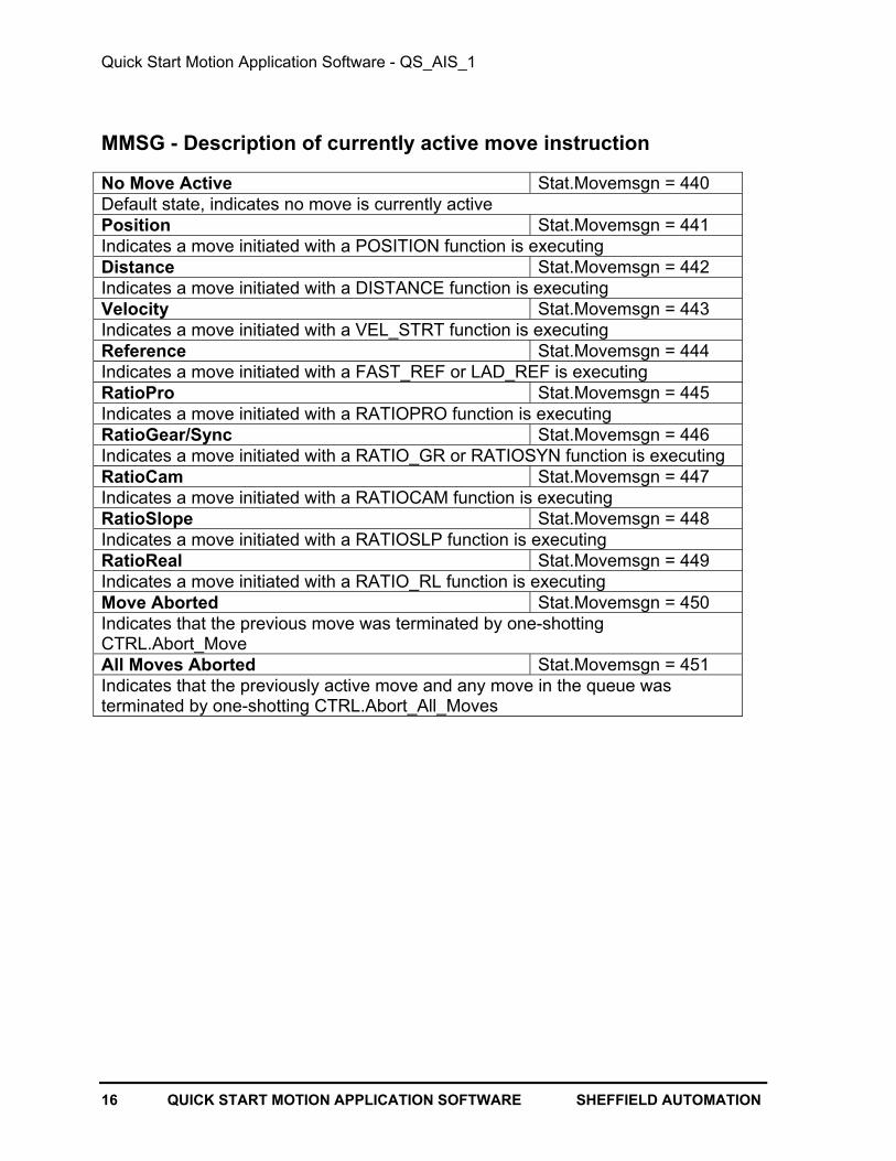
MMSG - Description of currently active move instruction
No Move Active Stat.Movemsgn = 440Default state, indicates no move is currently activePosition Stat.Movemsgn = 441Indicates a move initiated with a POSITION function is executingDistance Stat.Movemsgn = 442Indicates a move initiated with a DISTANCE function is executingVelocity Stat.Movemsgn = 443Indicates a move initiated with a VEL_STRT function is executingReference Stat.Movemsgn = 444Indicates a move initiated with a FAST_REF or LAD_REF is executingRatioPro Stat.Movemsgn = 445Indicates a move initiated with a RATIOPRO function is executingRatioGear/Sync Stat.Movemsgn = 446Indicates a move initiated with a RATIO_GR or RATIOSYN function is executingRatioCam Stat.Movemsgn = 447Indicates a move initiated with a RATIOCAM function is executingRatioSlope Stat.Movemsgn = 448Indicates a move initiated with a RATIOSLP function is executingRatioReal Stat.Movemsgn = 449Indicates a move initiated with a RATIO_RL function is executingMove Aborted Stat.Movemsgn = 450Indicates that the previous move was terminated by one-shottingCTRL.Abort_MoveAll Moves Aborted Stat.Movemsgn = 451Indicates that the previously active move and any move in the queue wasterminated by one-shotting CTRL.Abort_All_Moves

Quick Start Motion Application Software - QS_AIS_1
SHEFFIELD AUTOMATION QUICK START MOTION APPLICATION SOFTWARE 17
JMSG - Description of Jog Operation State
Jog Plus Active Stat.Jogmsgn = 460Indicates that a jog move in the plus direction has been initiated by energizing JOG.PlusJog Minus Active Stat.Jogmsgn = 461Indicates that a jog move in the minus direction has been initiated by energizingJOG.MinusJog Terminated Stat.Jogmsgn = 462Indicates that a jog plus or minus move has been terminated by de-energizing JOG.Plusor JOG.MinusJog Incremental Plus StatJogmsgn = 463Indicates that a distance move in the positive direction has been initiated by energizingJOG.Incremental_PlusJog Incremental Minus Stat.Jogmsgn = 464Indicates that a distance move in the negative direction has beed initiated by energizingJOG.Incremental_MinusJog Incremental Done Stat.Jogmsgn = 465Indicates that the axis has moved the distance specified by JOG.Incremental_DistanceJog Incremental Aborted Stat.Jogmsgn = 466Indicates that a Jog Incremental move was aborted by energizingJOG.Incremental_AbortJog Handwheel Active Stat.Jogmsgn = 467Indicates that the jog handwheel mode has been initiated by energizingJOG.Handwheel_ModeJog Handwheel Done Stat.Jogmsgn = 468Indicates that the jog handwheel mode has been exited by de-energizingJOG.Handwheel_ModeCan’t Jog-Fault Present Stat.Jogmsgn = 469Indicates that a jog operation was requested while a C Stop or E Stop fault was presentCan’t Jog-Rate Zero Stat.Jogmsgn = 470Indicates that a Jog.Plus or Jog.Minus operation with Jog.Rate set to zero wasrequested. Or a Jog.Incremental_Plus or Jog.Incremental_Minus operation wasrequested with Jog.Incremental_Rate set to zero was requested.Can’t Jog-Move Active Stat.Jogmsgn = 471Indicates that any Jog operation was requested while there was a move already in thequeue.Can’t Jog Plus-End of Travel Stat.Jogmsgn = 472Indicates that a Jog.Plus or Jog.Incremental_Plus was requested whileCTRL.Plus_End_of_Travel was energized.Can’t Jog Minus-End of Travel Stat.Jogmsgn = 473Indicates that a Jog.Minus or Jog.Incremental_Minus was requested whileCTRL. Minus_End_of_Travel was energizedCan’t Jog-End of Travel Stat.Jogmsgn = 474Indicates that a Jog.Handwheel_Mode was requested while eitherCTRL.Plus_End_of_Travel or CTRL.Minus_End_of_Travel was energized

Quick Start Motion Application Software - QS_AIS_1
18 QUICK START MOTION APPLICATION SOFTWARE SHEFFIELD AUTOMATION
HMSG - Description of Home Cycle Operation State
Autobackoff Home Switch Stat.Homemsgn = 480Indicates that when Home Cycle was activated the Home Switch was ON andAutobackoff was enabled and the axis is being moved in the opposite of thehome direction at the home rate until the home switch is OFF.Moving to Home Switch Stat.Homemsgn = 481- Indicates that the axis is being moved toward the Home Switch in the homedirection at the home rate.Moving to Park Position Stat.Homemsgn = 482Indicates that homing has completed and the axis is being moved to the parkposition.Home Successful Stat.Homemsgn = 483- Indicates that the home cycle has completed successfully. Is cleared at start ofhome cycle or if a Loss of Feedback fault is detected.Can’t Home-Fault Present Stat.Homemsgn = 484- Indicates that an E Stop or C Stop fault was present when the request to startthe home cycle was made.Can’t Home-Move Active Stat.Homemsgn = 485- Indicates that a servo move was already active when the request to start thehome cycle was made.Can’t Home-End of Travel Stat.Homemsgn = 486- Indicates CTRL.Plus_End_of_Travel or CTRL.Minus_End_of_Travel is ONpreventing the Home cycle from starting.Can’t Home-On Home Switch Stat.Homemsgn = 487- Indicates that when the Home cycle was requested the Home Switch is ON andHome.Auto_Backoff_Home_Switch is OFF preventing the Home cycle fromstarting.Can’t Move to Park-Rate Zero Stat.Homemsgn = 488- Indicates that Home.Move_to_Park_After_Home is ON and Home.Park_Rate iszero preventing the move to park position from being done.Home Aborted Stat.Homemsgn = 489- Indicates that the home cycle was aborted without completing successfully.Can’t Home-Rate Zero Stat.Homemsgn = 490- Indicates that the home cycle could not be executed because the Home Rate iszero.
Quick Start Motion Application Software - QS_AIS_1
SHEFFIELD AUTOMATION QUICK START MOTION APPLICATION SOFTWARE 19
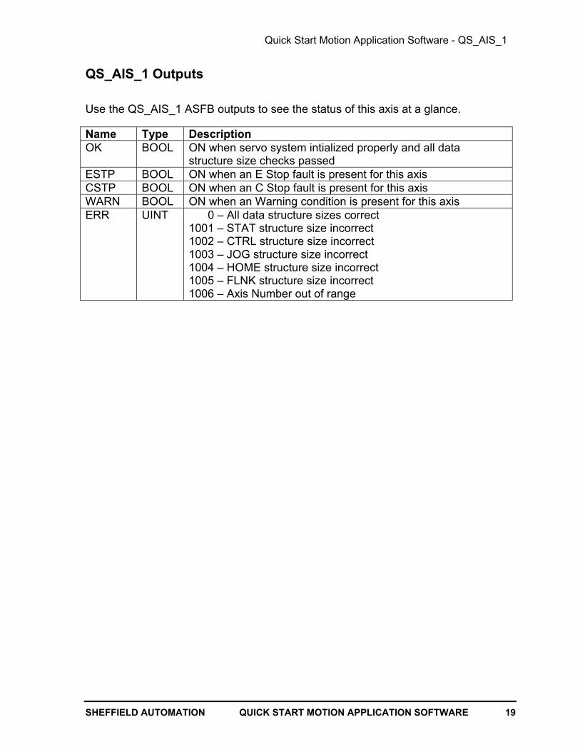
QS_AIS_1 Outputs
Use the QS_AIS_1 ASFB outputs to see the status of this axis at a glance.
Name Type DescriptionOK BOOL ON when servo system intialized properly and all data
structure size checks passedESTP BOOL ON when an E Stop fault is present for this axisCSTP BOOL ON when an C Stop fault is present for this axisWARN BOOL ON when an Warning condition is present for this axisERR UINT 0 – All data structure sizes correct
1001 – STAT structure size incorrect1002 – CTRL structure size incorrect1003 – JOG structure size incorrect1004 – HOME structure size incorrect1005 – FLNK structure size incorrect1006 – Axis Number out of range
Quick Start Motion Application Software - QS_AIS_1
20 QUICK START MOTION APPLICATION SOFTWARE SHEFFIELD AUTOMATION
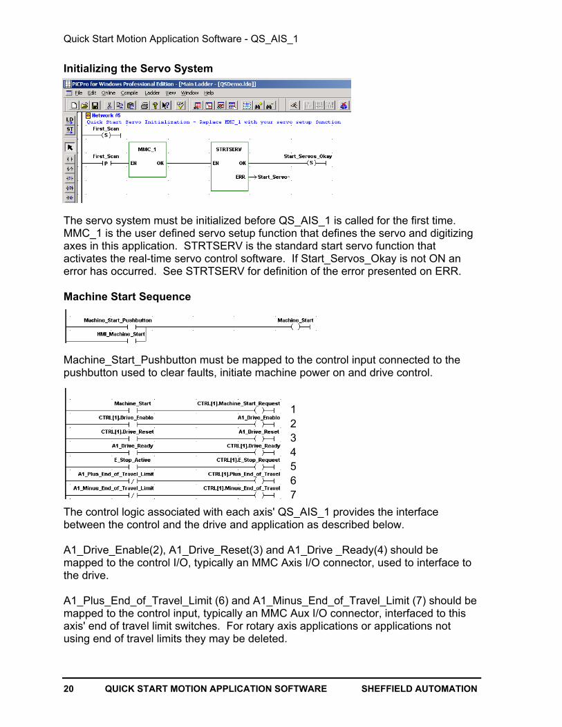
Initializing the Servo System
The servo system must be initialized before QS_AIS_1 is called for the first time.MMC_1 is the user defined servo setup function that defines the servo and digitizingaxes in this application. STRTSERV is the standard start servo function thatactivates the real-time servo control software. If Start_Servos_Okay is not ON anerror has occurred. See STRTSERV for definition of the error presented on ERR.
Machine Start Sequence
Machine_Start_Pushbutton must be mapped to the control input connected to thepushbutton used to clear faults, initiate machine power on and drive control.
The control logic associated with each axis' QS_AIS_1 provides the interfacebetween the control and the drive and application as described below.
A1_Drive_Enable(2), A1_Drive_Reset(3) and A1_Drive _Ready(4) should bemapped to the control I/O, typically an MMC Axis I/O connector, used to interface tothe drive.
A1_Plus_End_of_Travel_Limit (6) and A1_Minus_End_of_Travel_Limit (7) should bemapped to the control input, typically an MMC Aux I/O connector, interfaced to thisaxis' end of travel limit switches. For rotary axis applications or applications notusing end of travel limits they may be deleted.
1234567

Quick Start Motion Application Software - QS_AIS_1
SHEFFIELD AUTOMATION QUICK START MOTION APPLICATION SOFTWARE 21
Pulsing CTRL[1].Machine_Start_Request (1) initiates the machine start sequence.This sequence clears faults specific to the controlled axis, energizesCTRL[1].Drive_Reset (3) for one scan if CTRL[1].Drive_Ready (4) is not on thenwaits the time specified by CTRL[1].Wait_for_Drive_Ready_Delay (default time 2seconds). At the end of the time delay faults will be cleared again andCTRL[1].Drive_Enable will be energized, the servo position loop will be closed andfault monitoring will be activated.
Energize, instead of pulsing, CTRL[1].Machine_Start_Request (1), to forceQS_AIS_1 to not recognize the fault normally generated by the plus (6) and minus(7) end of travel limits. This allows the user to jog off an end limit switch.
E_Stop_Pushbutton (Emergency Stop) must be mapped to a control input asrequired by the machine safety directives being followed for this control application.Power_On_Relay must be mapped to a control output for control of the machinepower on circuit and must be deenergized as required by the machine safetydirectives being followed for this control application. Proper adherence to machinesafety directives is the responsibility of the user applying control.
Fault Control
QS_AIS_1 monitors the CTRL structure inputs, the servo software status and otheraxes fault status to provide fault control for the axis it is controlling.
QS_AIS_1 monitors three types of faults:
E Stop - E Stop faults will cause the servo position loop to open and theCTRL[1].Drive_Enable to turn off and will generate a Fault Link E Stop Request to allother axes integrated using FLNK and the QS_FLT_1 fault manager. If an E Stopcondition is detected after either a Warning or C Stop condition has been detectedthe E Stop will take precedence.
C Stop - C Stop faults will cause the axis to decellerate to zero at the controlled stopdecel rate specified by the applications servo setup function and will generate a FaultLink C Stop Request to all other axes integrated using FLNK and the QS_FLT_1 faultmanager. If a C Stop condition is detected after a Warning condition has beendetected the C Stop will take precedence.
Warning - Warning conditions have no effect on the operation of the servo task butare monitored and logged by the fault manager QS_FLT_1.

Quick Start Motion Application Software - QS_AIS_1
22 QUICK START MOTION APPLICATION SOFTWARE SHEFFIELD AUTOMATION
Faults are cleared by pulsing CTRL[1].Machine_Start_Request. The FLNK input isused to cause this axis to enter a fault condition if another axis' QS_AIS_1 functiondetects a fault. QS_FLT_1 monitors and logs the overall fault status.
See the SMSG section of this document for a comprehensive list of fault conditionsmonitored by QS_AIS_1 and the text messages used to present the fault status.
See the QS_FLT_1 document for information regarding the integration of faults inmulti-axis systems and to learn how to integrate application specific E Stop and CStop faults and Warning conditions.

Quick Start Motion Application Software - QS_AIS_1
SHEFFIELD AUTOMATION QUICK START MOTION APPLICATION SOFTWARE 23
Servo Axis Numbers and Axis Descriptions
The table below shows the relationship between the numbering of the servo axesused by QS_AIS_1, 1 to 32, and the control servo software, 1 to 16, and 101 to 116.It also shows the default text descriptions of the axes used in control text messages(STAT[axis].Description and used by the Cimrex C69 operator interface. The textdescriptions of the axes can be changed to be specific to the application. Startingapplication specific descriptions with "A1 " to "A32 " will aid in troubleshooting. Also,the text descriptions are limited to 22 characters.
Control Cimrex Message Library
QS_AIS_1Axis
Number
ServoSoftware
Axis NumberSTAT[axis].Description Message Number Text
1 1 Axis 1 1 Axis 1 2 2 Axis 2 2 Axis 23 3 Axis 3 3 Axis 34 4 Axis 4 4 Axis 45 5 Axis 5 5 Axis 56 6 Axis 6 6 Axis 67 7 Axis 7 7 Axis 78 8 Axis 8 8 Axis 89 9 Axis 9 9 Axis 9
10 10 Axis 10 10 Axis 1011 11 Axis 11 11 Axis 1112 12 Axis 12 12 Axis 12 13 13 Axis 13 13 Axis 13 14 14 Axis 14 14 Axis 1415 15 Axis 15 15 Axis 1516 16 Axis 16 16 Axis 1617 101 Axis 17 17 Axis 1718 102 Axis 18 18 Axis 1819 103 Axis 19 19 Axis 1920 104 Axis 20 20 Axis 2021 105 Axis 21 21 Axis 2122 106 Axis 22 22 Axis 2223 107 Axis 23 23 Axis 2324 108 Axis 24 24 Axis 2425 109 Axis 25 25 Axis 2526 110 Axis 26 26 Axis 2627 111 Axis 27 27 Axis 2728 112 Axis 28 28 Axis 2829 113 Axis 29 29 Axis 2930 114 Axis 30 30 Axis 3031 115 Axis 31 31 Axis 3132 116 Axis 32 32 Axis 32

Quick Start Motion Application Software - QS_AIS_1
24 QUICK START MOTION APPLICATION SOFTWARE SHEFFIELD AUTOMATION
Digitized (Feedback only) Axis Numbers and Descriptions
The table below shows the relationship between the numbering of the digitized axesused by QS_AIS_1, 1 to 32, and the control servo software, 49 to 80. It also showsthe default text descriptions of the digitized axes used in control text messagesDCTL[axis].Description and used by the Cimrex C69 operator interface. The textdescriptions of digitized axes can be changed to be specific to the application.Starting application specific descriptions with "D1 " to "D32 " will aid introubleshooting. Also, the text descriptions are limited to 22 characters.
Control Cimrex Message Library
QS_AIS_1Digitized
Axis
Servo SoftwareDigitized
Axis NumberDCTL[axis].Description
MessageNumber Text
1 49 Digitized 1 49 Digitized 1 2 50 Digitized 2 50 Digitized 23 51 Digitized 3 51 Digitized 34 52 Digitized 4 52 Digitized 45 53 Digitized 5 53 Digitized 56 54 Digitized 6 54 Digitized 67 55 Digitized 7 55 Digitized 78 56 Digitized 8 56 Digitized 89 57 Digitized 9 57 Digitized 9
10 58 Digitized 10 58 Digitized 1011 59 Digitized 11 59 Digitized 1112 60 Digitized 12 60 Digitized 12 13 61 Digitized 13 61 Digitized 13 14 62 Digitized 14 62 Digitized 1415 63 Digitized 15 63 Digitized 1516 64 Digitized 16 64 Digitized 1617 65 Digitized 17 65 Digitized 1718 66 Digitized 18 66 Digitized 1819 67 Digitized 19 67 Digitized 1920 68 Digitized 20 68 Digitized 2021 69 Digitized 21 69 Digitized 2122 70 Digitized 22 70 Digitized 2223 71 Digitized 23 71 Digitized 2324 72 Digitized 24 72 Digitized 2425 73 Digitized 25 73 Digitized 2526 74 Digitized 26 74 Digitized 2627 75 Digitized 27 75 Digitized 2728 76 Digitized 28 76 Digitized 2829 77 Digitized 29 77 Digitized 2930 78 Digitized 30 78 Digitized 3031 79 Digitized 31 79 Digitized 3132 80 Digitized 32 80 Digitized 32

Quick Start Motion Application Software - QS_AIS_1
SHEFFIELD AUTOMATION QUICK START MOTION APPLICATION SOFTWARE 25
Troubleshooting QS_AIS_1
In case of difficulties use PiCPro's animation and view capability to observe theoperation of QS_AIS_1.
If the OK output of QS_AIS_1 is OFF there is a programming error. Check for:
Problem Servo position loop won't closeQS_AIS_1
OutputConditions
OK = OFFERR <> 0SMSG = Programming Error
1 - Check ERR: ERR = 1001 – STAT structure size incorrect ERR = 1002 – CTRL structure size incorrect ERR = 1003 – JOG structure size incorrect ERR = 1004 – HOME structure size incorrect ERR = 1005 – FLNK structure size incorrectIf an incorrect structure size error occurred make sure that the correct structure isprogrammed as the input to QS_AIS_1, that the structures array index is not greater than itsarray size in software declarations and that a revision changing the number of members inthe structure has not occurred. ERR = 1006 – Axis Number out of rangeQS_AIS_1 supports axis numbers 1 to 32 and translates them to the servo software axisnumbers 1 to 16 for AXIS 1 to 16 and 101 to 117 for AXIS 17 to 32.
Problem Servo position loop won't closeQS_AIS_1
OutputConditions
OK = OFFERR = 0SMSG = Axis Not Initialized
The servo axis specified by the QS_AIS_1 Axis input was not included in the servo setup function or an error occurred when the servo setup function was called. 1 - Check the servo setup function network to see if an error was reported. 2 - Open the servo setup function and make sure the axis is defined. 3 - Check the QS_AIS_1 axis input and make sure the axis number is correct.
If the OK output of QS_AIS_1 is ON but the servo loop won't close. Check for:
Problem Machine Start won't close the servo position loop QS_AIS_1
OutputConditions
OK = ONERR = 0SMSG = First Scan E Stop
This is the normal state of SMSG after control power on or restart of the scan. SMSG neverindicates First Scan E Stop after the first time CTRL.Machine_Start_Request is ON. 1 - To clear faults and start the close loop sequence CTRL.Machine_Start_Request mustmake a transition from OFF to ON. Check to make sure that it is not on all of the time. 2 - Check to make sure CTRL.Machine_Start goes on when the control input used to actuateit goes ON.3 - Check the C69 fault history for First Scan E Stop faults - each one indicates that thecontrol power has been powered on or the control scan has been stopped and restarted.

Quick Start Motion Application Software - QS_AIS_1
26 QUICK START MOTION APPLICATION SOFTWARE SHEFFIELD AUTOMATION
Problem On Machine Start SMSG immediately indicates E Stop RequestQS_AIS_1
OutputConditions
OK = ONERR = 0SMSG = E Stop Request
If CTRL.E_Stop_Request goes ON during the Machine Start sequence the Machine Start inProcess is cancelled and QS_AIS_1 immediately enters the E Stop state.1 - Check the logic driving CTRL.E_Stop_Request to determine why it is energizing.
Problem After Machine Start SMSG indicates Machine Start in Process forever or fora very long time.
QS_AIS_1Output
Conditions
OK = ONERR = 0SMSG = Machine Start in Process
After Machine Start SMSG will indicate Machine Start in Process for the length of timespecified by CTRL.Wait_For_Drive_Ready_Delay. At the end of that time Drive Enable willbe energized and the servo position loop will close. The intent of the time delay is to allowenough time for the machine power on circuit to provide power to the servo amplifier and forthe amplifier to be ready to control the motor.1 - Check the value in CTRL.Wait_For_Drive_Ready_Delay and reduce it if necessary. Thedefault value is two seconds.
Problem After Machine Start the servo position loop won't close
QS_AIS_1Output
Conditions
OK = ONERR = 0ESTP = ONSMSG = Drive Not Ready
This inidicates that CTRL.Drive_Ready was not on at the end of the machine startsequence or has gone off indicating a drive fault.1 - Check that the drive is powered on and that drive faults are cleared.2 - Check the plug-and-play axis interface cable between the control and drive.3 - Check the logic driving CTRL.Drive_Ready.4 - Check to see that the coil CTRL.Drive_Ready is energizing is mapped to an output inSoftware Declarations.
Problem Servo position loop closed but motor does not seem to be in servo lockQS_AIS_1
OutputConditions
OK = ONERR = 0 SMSG = Loop Closed - No Fault
1 - Check to see that the servo amplifier powered on. Check the Power On circuit.2 - CTRL.Drive_Enable should be ON. Check to see that CTRL.Drive_Enable is connectedto the control output used to enable the servo amplifier. Check to see that the coilCTRL.Drive_Ready is energizing is mapped to an output in Software Declarations.3 - Make sure the servo amplifier is receiving the Drive Enable signal.4 - Make sure the servo amplifier is configured for velocity mode operation.5 - Check that the servo amplifier current limits are set to allow current output to the motor.6 - If the servo amplifier is configured to allow external inputs to prevent motion are they ON.7 - Check the plug-and-play axis interface cable between the control and drive.8 - Check that the servo amplifier is receiving the analog velocity command from the control.

Quick Start Motion Application Software - QS_AIS_1
SHEFFIELD AUTOMATION QUICK START MOTION APPLICATION SOFTWARE 27
If the OK output of QS_AIS_1 is ON and the servo loop closes but anE Stop fault occurs. Check for:
Problem Servo position loop closes but fault occurs when motion attempted.
QS_AIS_1Output
Conditions
OK = ONERR = 0ESTP = ONSMSG = Excess Following Error
If the axis was previously operating properly: 1 - Check for mechanical bind up of the servo axis. 2 - Check to see that the servo amplifier powered on. Check the Power On circuit. Check for blown fuses. 3 - Check the plug-and-play axis interface cable between the control and drive. 4 - Check that the servo amplifier is receiving the analog velocity command from the control.If this is a new startup and the axis was not previously operating properly: 1 - Use View Status 5 - Limits to check the Maximum Following Error limit. Is it zero? 2 - Use View Status 4 - Tuning to check Position Loop P Gain. Is it zero? 3 - Make sure the servo amplifier is configured for velocity mode operation. 4 - Check to make sure servo amplifier Velocity Loop gain settings are appropriate. 5 - Check that the servo amplifier current limits are set to allow current output to the motor. 6 - If the servo amplifier is configured to allow external inputs to prevent motion are they ON.
Problem Servo position loop closes but fault occursQS_AIS_1
OutputConditions
OK = ONERR = 0SMSG = E Stop Request
1 - Check the logic driving CTRL.E_Stop_Request to determine why it is energizing.Problem Servo position loop closes but no motion occurs when motion attempted.
QS_AIS_1Output
Conditions
OK = ONERR = 0ESTP = OFFSMSG = Loop Closed - No FaultMMSG = indicates type of move requested
1 - Use Servo Setup to check that the Acceleration and Deceleration Ramp rates are notzero or so small that the axis velocity ramp up will take a very long time.
Problem Servo position loop closes but Loss of Feedback fault occurs.
QS_AIS_1Output
Conditions
OK = ONERR = 0ESTP = ONSMSG = Loss of Feedback
1 - Check the plug-and-play axis interface cable between the control and drive.2 - Check cable routing of plug-and-play axis interface cable to make sure it is not nearmotor power cables or other electrical noise sources.
Problem Servo position loop closes but Math Overflow Error fault occurs.
QS_AIS_1Output
Conditions
OK = ONERR = 0ESTP = ONSMSG = Math Overflow Error
1 - See the E_Errors function description of the Overflow Error for a detailed description ofthe cause of this fault.

Quick Start Motion Application Software - QS_AIS_1
28 QUICK START MOTION APPLICATION SOFTWARE SHEFFIELD AUTOMATION
Problem Servo position loop closes but User Set E Stop fault occurs.
QS_AIS_1Output
Conditions
OK = ONERR = 0ESTP = ONSMSG = User Set E Stop
1 - The application program is executing the E_STOP function. Use the QS_FLT_1application specific E Stop capability instead of E_STOP to generate an E Stop fault with anapplication specific description.
Problem Servo position loop closes but Plus End of Travel fault occurs.
QS_AIS_1Output
Conditions
OK = ONERR = 0ESTP = ONSMSG = Plus End of Travel
1 - Check the logic driving CTRL.Plus_End_of_Travel, it turned on causing this fault. Notethat energizing machine start will ignore the plus end of travel limit and QS_AIS_1 will allowjogging in the minus direction while the plus end of travel is on.
Problem Servo position loop closes but Minus End of Travel fault occurs.
QS_AIS_1Output
Conditions
OK = ONERR = 0ESTP = ONSMSG = Minus End of Travel
1 - Check the logic driving CTRL.Minus_End_of_Travel, it turned on causing this fault. Notethat energizing machine start will ignore the minus end of travel limit and QS_AIS_1 willallow jogging in the plus direction while the minus end of travel is on.
Problem Servo position loop closes but Fault Link E Stop Request fault occurs.
QS_AIS_1Output
Conditions
OK = ONERR = 0ESTP = ONSMSG = Fault Link E Stop Request
1 - Check the FSTR output of QS_FLT_1, it will indicate which servo or digitized axis enteredthe E Stop Fault state first causing this axis to enter E Stop via a Fault Link E Stop Request.
Problem After the first fault occurs Machine Start won't clear faults.QS_AIS_1
OutputConditions
OK = ONERR = 0SMSG = last fault that occurred
1 - To clear faults and start the close loop sequence CTRL.Machine_Start_Request mustmake a transition from OFF to ON. Check to make sure that it is not on all of the time. 2 - Check to make sure CTRL.Machine_Start goes on when the control input used to actuateit goes ON.
If the OK output of QS_AIS_1 is ON and the servo loop closes but aC Stop fault occurs. Check for:
Problem Servo position loop closes but fault occurs.
QS_AIS_1Output
Conditions
OK = ONERR = 0CSTP = ONSMSG = C Stop Request
1 - Check the logic driving CTRL.C_Stop_Request to determine why it is energizing.

Quick Start Motion Application Software - QS_AIS_1
SHEFFIELD AUTOMATION QUICK START MOTION APPLICATION SOFTWARE 29
Problem Servo position loop closes but fault occurs.
QS_AIS_1Output
Conditions
OK = ONERR = 0CSTP = ONSMSG = Plus Software Endlimit Exceeded
1 - Use View Status 5 - Limits to check Ignore Software Limits and the Soft Plus Limit. Inservo setup Ignore Soft Limits till Referenced can be selected.
Problem Servo position loop closes but fault occurs.
QS_AIS_1Output
Conditions
OK = ONERR = 0CSTP = ONSMSG = Minus Software Endlimit Exceeded
1 - Use View Status 5 - Limits to check Ignore Software Limits and the Soft Minus Limit. Inservo setup Ignore Soft Limits till Referenced can be selected.
Problem Servo position loop closes but fault occurs.
QS_AIS_1Output
Conditions
OK = ONERR = 0CSTP = ONSMSG = User Defined C Stop
1 - The application program is executing the C_STOP function. Use the QS_FLT_1application specific C Stop capability instead of C_STOP to generate an C Stop fault with anapplication specific description.
Problem Servo position loop closes but fault occurs.
QS_AIS_1Output
Conditions
OK = ONERR = 0CSTP = ONSMSG = Machine Ref. Dim. Error
1 - A calculation overflow occurred when scaling data, see C_Errors function for detailedexplanation.
Problem Servo position loop closes but fault occurs.
QS_AIS_1Output
Conditions
OK = ONERR = 0CSTP = ONSMSG = Feedrate Error
1 - A calculation overflow occurred when scaling data or the specified feedrate exceeded thelimit specified in the servo setup function, see C_Errors function for detailed explanation.
Problem Servo position loop closes but fault occurs.
QS_AIS_1Output
Conditions
OK = ONERR = 0CSTP = ONSMSG = Distance/Position Dim. Error
1 - A calculation overflow occurred when scaling data, see C_Errors function for detailedexplanation.
Problem Servo position loop closes but fault occurs.
QS_AIS_1Output
Conditions
OK = ONERR = 0CSTP = ONSMSG = Par Ref. Dimension Error
1 - A calculation overflow occurred when scaling data, see C_Errors function for detailedexplanation.

Quick Start Motion Application Software - QS_AIS_1
30 QUICK START MOTION APPLICATION SOFTWARE SHEFFIELD AUTOMATION
Problem Servo position loop closes but fault occurs.
QS_AIS_1Output
Conditions
OK = ONERR = 0CSTP = ONSMSG = Part Ref. While in Motion
1 - The application program called the Part_Ref function while a move was in process.Correct the application program logic so Part_Ref is only called with no move active.
Problem Servo position loop closes but fault occurs.
QS_AIS_1Output
Conditions
OK = ONERR = 0CSTP = ONSMSG = Fault Link C Stop Request
1 - Check the FSTR output of QS_FLT_1, it will indicate which servo or digitized axisentered the C Stop Fault state first causing this axis to enter C Stop via a Fault Link CStop Request.
If the OK output of QS_AIS_1 is ON and the servo loop closes but aWarning condition is reported. Check for:
Problem Servo position loop closes but warning condition is reported.
QS_AIS_1Output
Conditions
OK = ONERR = 0WARN = ONSMSG = M/Slave Master Start Overflow
1 - A calculation overflow occurred when scaling data, see P_Errors function for detailedexplanation.
Problem Servo position loop closes but warning condition is reported.
QS_AIS_1Output
Conditions
OK = ONERR = 0WARN = ONSMSG = Master Axis Not Available
1 - The master axis specified in a ratio move was not initialized in the servo setupfunction or was otherwise unavailable, see P_Errors function for detailed explanation.
Problem Servo position loop closes but warning condition is reported.
QS_AIS_1Output
Conditions
OK = ONERR = 0WARN = ONSMSG = Profile Not Found
1 - The profile number specified in a RatioPro function was not valid.Problem Servo position loop closes but warning condition is reported.
QS_AIS_1Output
Conditions
OK = ONERR = 0WARN = ONSMSG = FAST Que Axis Out of Range
1 - The axis travelled more than 65,535 FU in the opposite direction of the valueentered in the DIST input of the FAST_QUE function.

Quick Start Motion Application Software - QS_AIS_1
SHEFFIELD AUTOMATION QUICK START MOTION APPLICATION SOFTWARE 31
Problem Servo position loop closes but warning condition is reported.
QS_AIS_1Output
Conditions
OK = ONERR = 0WARN = ONSMSG = Servo Timing Error
1 - The amount of processor time required to control all of the servo and digitizingaxes at the interrupt rates specified in the servo setup function is excessive. See theservo update rate specification table for the processor being used.