Embed Size (px)
Citation preview

Quick Start TutorialImperial version

© 1996-2006 Cadsoft Corporation. No part of this guide or the accompanying software may be reproduced or transmitted, electronically or mechanically, without written permission from CADSOFT Corporation. Reproduction and transmission includes, but is not limited to, photocopying, recording, and copying onto any storage and information retrieval system. Windows is either a registered trademark or a trademark of Microsoft Corporation in the United States and/or other countries. All other trademarks are the property of their respective owners.
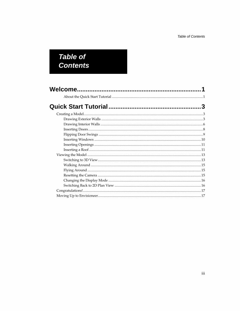
Table of Contents
iii
Table of ContentsWelcome.......................................................................1
About the Quick Start Tutorial .......................................................................................................1
Quick Start Tutorial .....................................................3Creating a Model.......................................................................................................................................3
Drawing Exterior Walls ...................................................................................................................3Drawing Interior Walls ....................................................................................................................6Inserting Doors..................................................................................................................................8Flipping Door Swings ......................................................................................................................9Inserting Windows .........................................................................................................................10Inserting Openings .........................................................................................................................11Inserting a Roof ...............................................................................................................................11
Viewing the Model .................................................................................................................................13Switching to 3D View.....................................................................................................................13Walking Around .............................................................................................................................15Flying Around .................................................................................................................................15Resetting the Camera .....................................................................................................................15Changing the Display Mode .........................................................................................................16Switching Back to 2D Plan View ..................................................................................................16
Congratulations!......................................................................................................................................17Moving Up to Envisioneer.....................................................................................................................17
Table of Contents

1
WelcomeWelcome to Envisioneer Express, a quick and easy modeling tool that helps you create home plans smoothly and efficiently, with the added versatility of 3D viewing and navigation.
Envisioneer Express contains many of the basic design and viewing features found in the full version of Envisioneer. Since most features are automated, it is very easy to learn and use. You can complete most tasks with a few clicks of the mouse. And with the built-in power of Cadsoft’s advanced design technology, you can count on fast, accurate drawings.
About the Quick Start TutorialThis guide is designed to get you up and running as quickly as possible. The step-by-step exercises will help you understand how the program works and give you the foundation you need to start your own design projects.
For more detailed information on each of the tools used, select Program Help from the Help menu.

Quick Start Tutorial 3
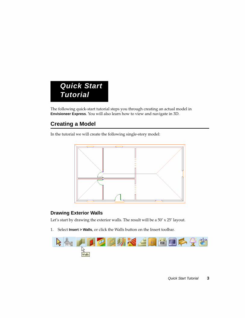
The following quick-start tutorial steps you through creating an actual model in Envisioneer Express. You will also learn how to view and navigate in 3D.
Creating a ModelIn the tutorial we will create the following single-story model:
Drawing Exterior WallsLet’s start by drawing the exterior walls. The result will be a 50’ x 25’ layout.
1. Select Insert > Walls, or click the Walls button on the Insert toolbar.
Quick Start Tutorial
Quick Start Tutorial
4 Envisioneer Express 3
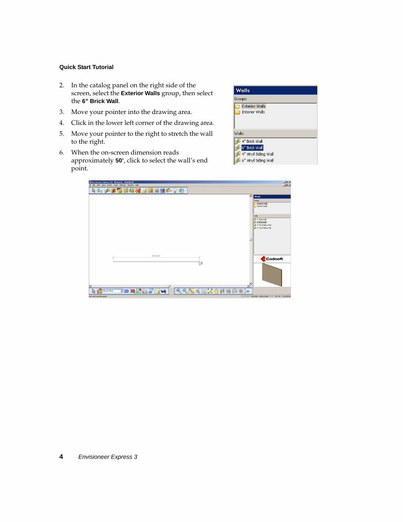
2. In the catalog panel on the right side of the screen, select the Exterior Walls group, then select the 6” Brick Wall.
3. Move your pointer into the drawing area.
4. Click in the lower left corner of the drawing area.
5. Move your pointer to the right to stretch the wall to the right.
6. When the on-screen dimension reads approximately 50’, click to select the wall’s end point.
Quick Start Tutorial 5
Creating a Model
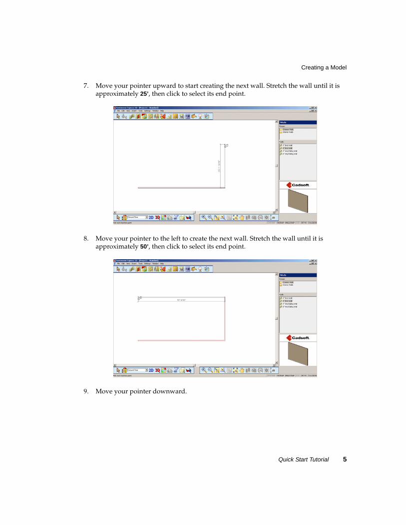
7. Move your pointer upward to start creating the next wall. Stretch the wall until it is approximately 25’, then click to select its end point.
8. Move your pointer to the left to create the next wall. Stretch the wall until it is approximately 50’, then click to select its end point.
9. Move your pointer downward.
Quick Start Tutorial
6 Envisioneer Express 3
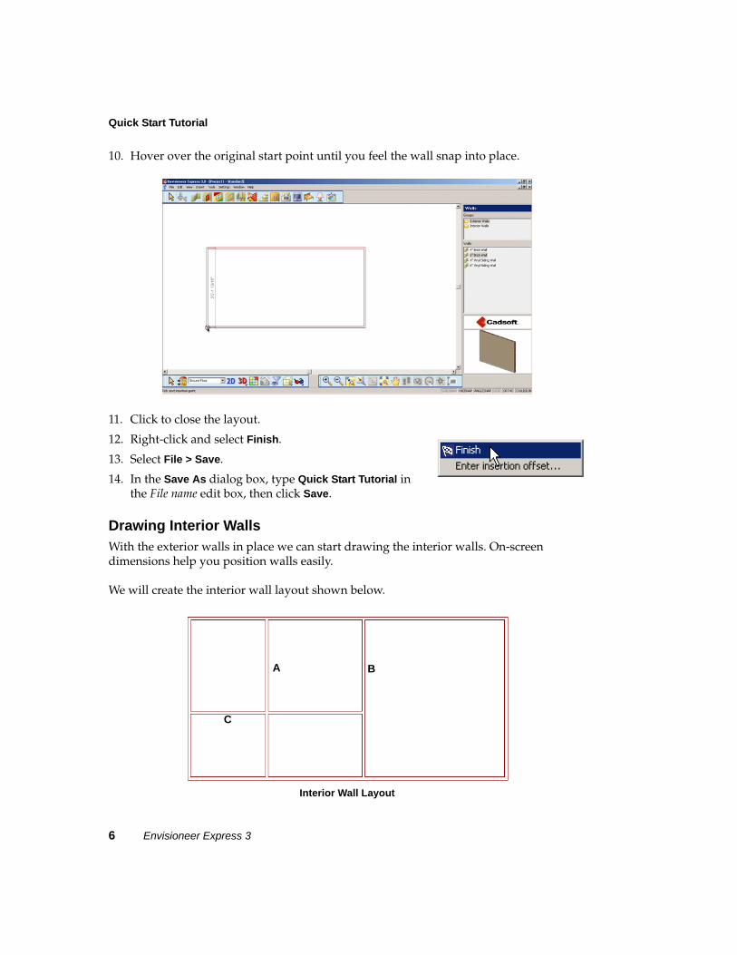
10. Hover over the original start point until you feel the wall snap into place.
11. Click to close the layout.
12. Right-click and select Finish.
13. Select File > Save.
14. In the Save As dialog box, type Quick Start Tutorial in the File name edit box, then click Save.
Drawing Interior WallsWith the exterior walls in place we can start drawing the interior walls. On-screen dimensions help you position walls easily.
We will create the interior wall layout shown below.
Interior Wall Layout
C
A B
Quick Start Tutorial 7
Creating a Model
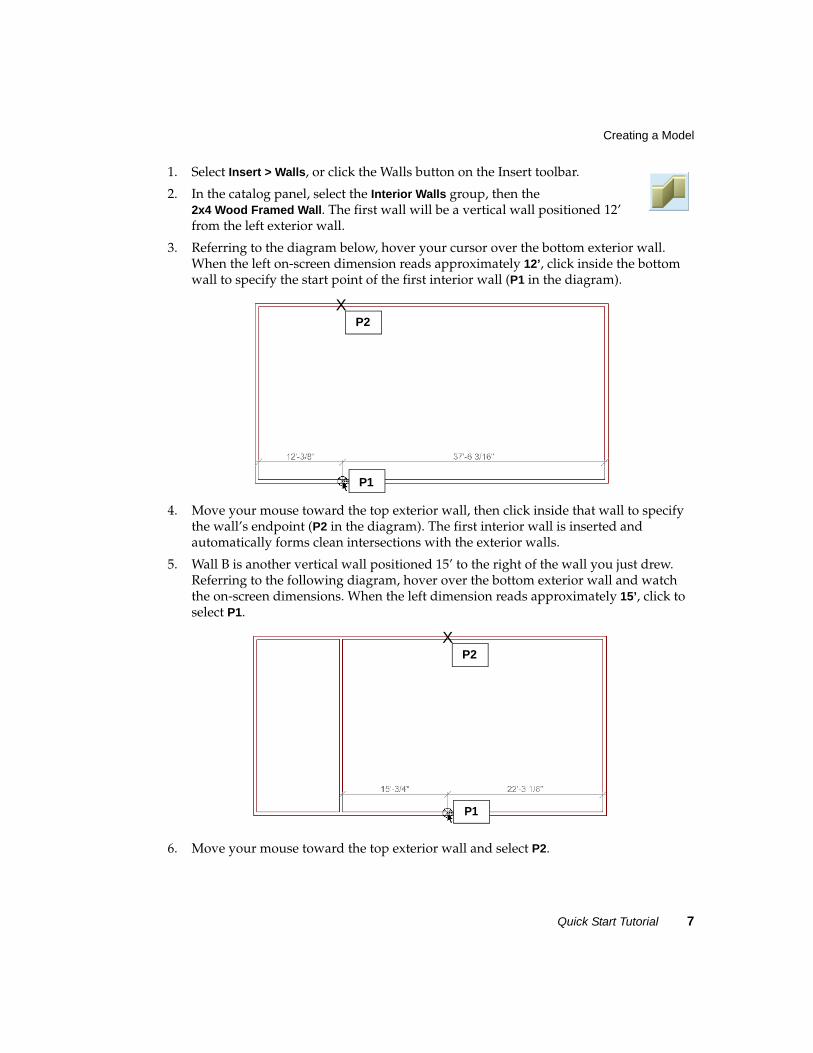
1. Select Insert > Walls, or click the Walls button on the Insert toolbar.
2. In the catalog panel, select the Interior Walls group, then the 2x4 Wood Framed Wall. The first wall will be a vertical wall positioned 12’ from the left exterior wall.
3. Referring to the diagram below, hover your cursor over the bottom exterior wall. When the left on-screen dimension reads approximately 12’, click inside the bottom wall to specify the start point of the first interior wall (P1 in the diagram).
4. Move your mouse toward the top exterior wall, then click inside that wall to specify the wall’s endpoint (P2 in the diagram). The first interior wall is inserted and automatically forms clean intersections with the exterior walls.
5. Wall B is another vertical wall positioned 15’ to the right of the wall you just drew. Referring to the following diagram, hover over the bottom exterior wall and watch the on-screen dimensions. When the left dimension reads approximately 15’, click to select P1.
6. Move your mouse toward the top exterior wall and select P2.
P1
P2X
P1
P2X
Quick Start Tutorial
8 Envisioneer Express 3
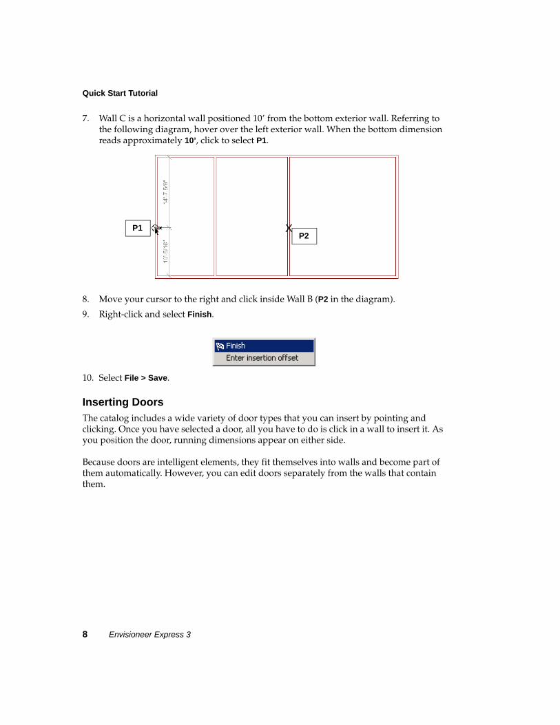
7. Wall C is a horizontal wall positioned 10’ from the bottom exterior wall. Referring to the following diagram, hover over the left exterior wall. When the bottom dimension reads approximately 10’, click to select P1.
8. Move your cursor to the right and click inside Wall B (P2 in the diagram).
9. Right-click and select Finish.
10. Select File > Save.
Inserting DoorsThe catalog includes a wide variety of door types that you can insert by pointing and clicking. Once you have selected a door, all you have to do is click in a wall to insert it. As you position the door, running dimensions appear on either side.
Because doors are intelligent elements, they fit themselves into walls and become part of them automatically. However, you can edit doors separately from the walls that contain them.
P1P2
X
Quick Start Tutorial 9
Creating a Model
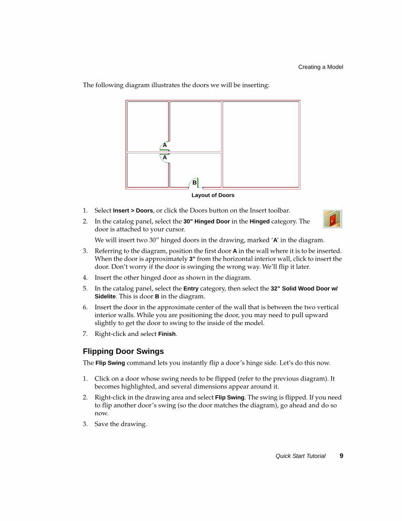
The following diagram illustrates the doors we will be inserting:
Layout of Doors
1. Select Insert > Doors, or click the Doors button on the Insert toolbar.
2. In the catalog panel, select the 30" Hinged Door in the Hinged category. The door is attached to your cursor.
We will insert two 30” hinged doors in the drawing, marked ‘A’ in the diagram.
3. Referring to the diagram, position the first door A in the wall where it is to be inserted. When the door is approximately 3” from the horizontal interior wall, click to insert the door. Don’t worry if the door is swinging the wrong way. We’ll flip it later.
4. Insert the other hinged door as shown in the diagram.
5. In the catalog panel, select the Entry category, then select the 32” Solid Wood Door w/ Sidelite. This is door B in the diagram.
6. Insert the door in the approximate center of the wall that is between the two vertical interior walls. While you are positioning the door, you may need to pull upward slightly to get the door to swing to the inside of the model.
7. Right-click and select Finish.
Flipping Door SwingsThe Flip Swing command lets you instantly flip a door’s hinge side. Let’s do this now.
1. Click on a door whose swing needs to be flipped (refer to the previous diagram). It becomes highlighted, and several dimensions appear around it.
2. Right-click in the drawing area and select Flip Swing. The swing is flipped. If you need to flip another door’s swing (so the door matches the diagram), go ahead and do so now.
3. Save the drawing.
A
B
A
Quick Start Tutorial
10 Envisioneer Express 3
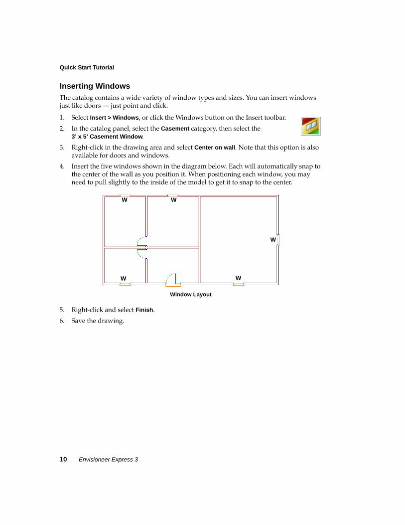
Inserting WindowsThe catalog contains a wide variety of window types and sizes. You can insert windows just like doors — just point and click.
1. Select Insert > Windows, or click the Windows button on the Insert toolbar.
2. In the catalog panel, select the Casement category, then select the 3’ x 5’ Casement Window.
3. Right-click in the drawing area and select Center on wall. Note that this option is also available for doors and windows.
4. Insert the five windows shown in the diagram below. Each will automatically snap to the center of the wall as you position it. When positioning each window, you may need to pull slightly to the inside of the model to get it to snap to the center.
Window Layout
5. Right-click and select Finish.
6. Save the drawing.
W
WW
W W
Quick Start Tutorial 11
Creating a Model
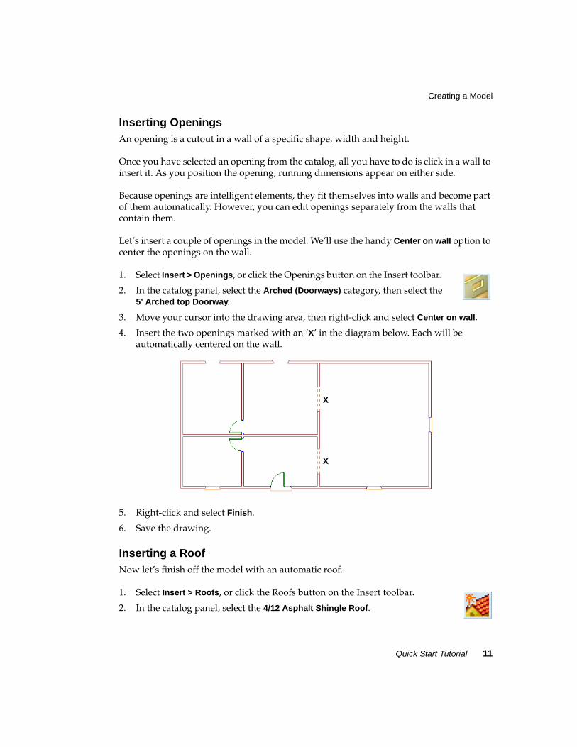
Inserting OpeningsAn opening is a cutout in a wall of a specific shape, width and height.
Once you have selected an opening from the catalog, all you have to do is click in a wall to insert it. As you position the opening, running dimensions appear on either side.
Because openings are intelligent elements, they fit themselves into walls and become part of them automatically. However, you can edit openings separately from the walls that contain them.
Let’s insert a couple of openings in the model. We’ll use the handy Center on wall option to center the openings on the wall.
1. Select Insert > Openings, or click the Openings button on the Insert toolbar.
2. In the catalog panel, select the Arched (Doorways) category, then select the 5’ Arched top Doorway.
3. Move your cursor into the drawing area, then right-click and select Center on wall.
4. Insert the two openings marked with an ‘X’ in the diagram below. Each will be automatically centered on the wall.
5. Right-click and select Finish.
6. Save the drawing.
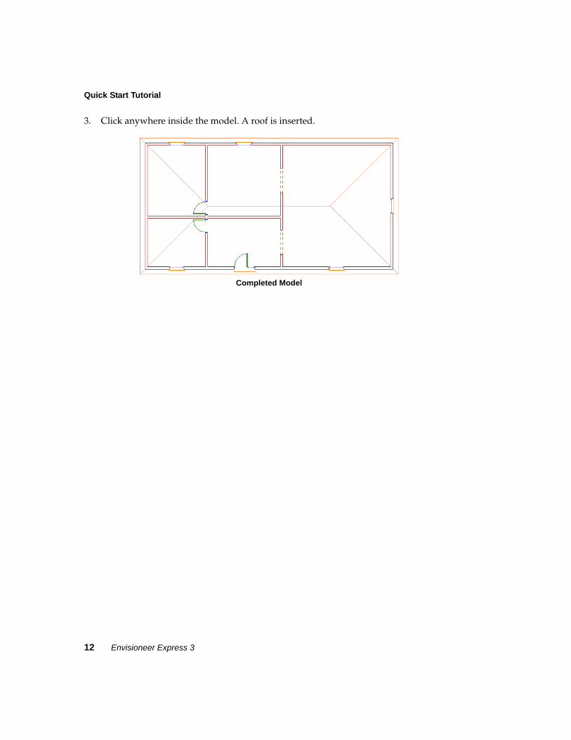
Inserting a RoofNow let’s finish off the model with an automatic roof.
1. Select Insert > Roofs, or click the Roofs button on the Insert toolbar.
2. In the catalog panel, select the 4/12 Asphalt Shingle Roof.
X
X
Quick Start Tutorial
12 Envisioneer Express 3
3. Click anywhere inside the model. A roof is inserted.
Completed Model
Quick Start Tutorial 13
Viewing the Model
Viewing the ModelEnvisioneer Express provides a variety of options for viewing your design. You can easily switch between 2D plan view and 3D view as often as you like while working.
3D views are controlled by a camera which you can move or adjust to change the view. You can also add more cameras for additional 3D views of the model. While in a 3D view you can also use the dynamic navigation commands, such as Walk Around and Slide, to view your model in an animated state.
Let’s switch to 3D view now and learn how to use some navigation commands.
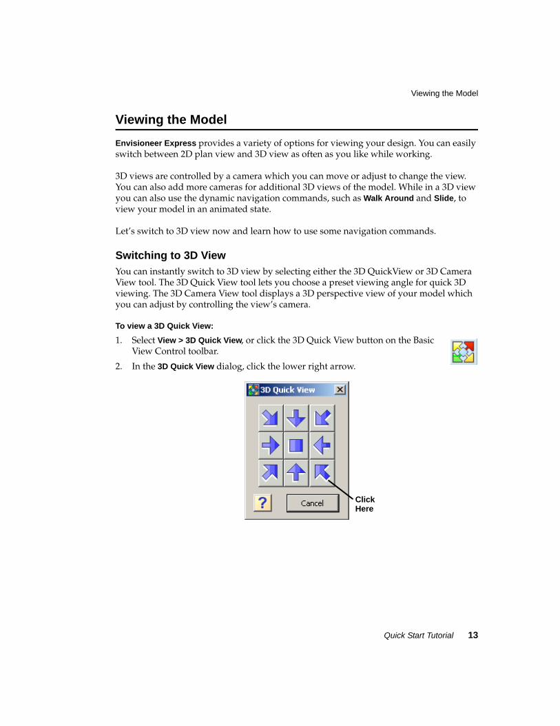
Switching to 3D ViewYou can instantly switch to 3D view by selecting either the 3D QuickView or 3D Camera View tool. The 3D Quick View tool lets you choose a preset viewing angle for quick 3D viewing. The 3D Camera View tool displays a 3D perspective view of your model which you can adjust by controlling the view’s camera.
To view a 3D Quick View:
1. Select View > 3D Quick View, or click the 3D Quick View button on the Basic View Control toolbar.
2. In the 3D Quick View dialog, click the lower right arrow.
ClickHere
Quick Start Tutorial
14 Envisioneer Express 3
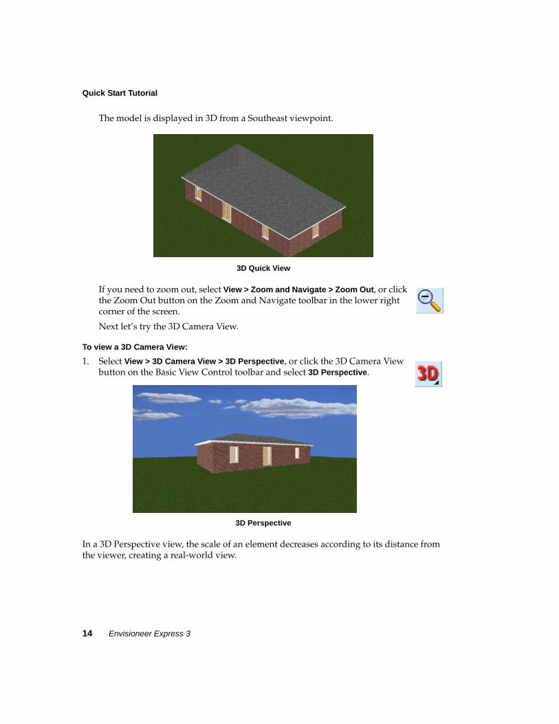
The model is displayed in 3D from a Southeast viewpoint.
3D Quick View
If you need to zoom out, select View > Zoom and Navigate > Zoom Out, or click the Zoom Out button on the Zoom and Navigate toolbar in the lower right corner of the screen.
Next let’s try the 3D Camera View.
To view a 3D Camera View:
1. Select View > 3D Camera View > 3D Perspective, or click the 3D Camera View button on the Basic View Control toolbar and select 3D Perspective.
3D Perspective
In a 3D Perspective view, the scale of an element decreases according to its distance from the viewer, creating a real-world view.
Quick Start Tutorial 15
Viewing the Model
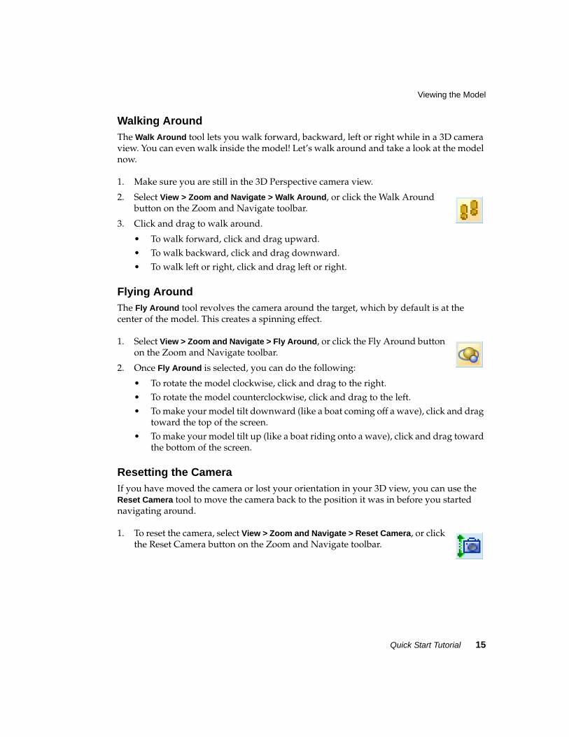
Walking AroundThe Walk Around tool lets you walk forward, backward, left or right while in a 3D camera view. You can even walk inside the model! Let’s walk around and take a look at the model now.
1. Make sure you are still in the 3D Perspective camera view.
2. Select View > Zoom and Navigate > Walk Around, or click the Walk Around button on the Zoom and Navigate toolbar.
3. Click and drag to walk around.
• To walk forward, click and drag upward.• To walk backward, click and drag downward.• To walk left or right, click and drag left or right.
Flying AroundThe Fly Around tool revolves the camera around the target, which by default is at the center of the model. This creates a spinning effect.
1. Select View > Zoom and Navigate > Fly Around, or click the Fly Around button on the Zoom and Navigate toolbar.
2. Once Fly Around is selected, you can do the following:
• To rotate the model clockwise, click and drag to the right.• To rotate the model counterclockwise, click and drag to the left.• To make your model tilt downward (like a boat coming off a wave), click and drag
toward the top of the screen.• To make your model tilt up (like a boat riding onto a wave), click and drag toward
the bottom of the screen.
Resetting the CameraIf you have moved the camera or lost your orientation in your 3D view, you can use the Reset Camera tool to move the camera back to the position it was in before you started navigating around.
1. To reset the camera, select View > Zoom and Navigate > Reset Camera, or click the Reset Camera button on the Zoom and Navigate toolbar.
Quick Start Tutorial
16 Envisioneer Express 3
Changing the Display ModeBy default, your design is displayed in Wireframe mode when you are in 2D plan view. When you switch to a 3D view, the default display mode is Rendered mode, which displays textures and colors. There are four display modes you can choose from.
To change the display mode of the current view:
1. Select View > Display Mode, or click the Display Mode button on the Basic View Control toolbar. Then, make a selection from the flyout.
2. Go ahead and experiment with the display modes now. Each one is described below.
Wireframe. Provides a skeletal representation of elements, creating a “see-through” view.
Hidden Line. Lines that you wouldn't normally see are hidden from view, creating a solid, non-color view.
Rendered. Applies textures and colors to element surfaces, creating a realistic view.
Rendered Outline. Same as the Rendered display mode, except surface edges are also outlined with a single, black line for high definition.
Switching Back to 2D Plan ViewWhen you are in a 3D view, you can switch back to 2D plan view at any time using the 2D Plan View tool. Let’s do this now.
• Click the 2D Plan View button on the Basic View Control toolbar.or
• Select View > 2D Plan View.or
• Right-click in the drawing area and select 2D Plan View.
Quick Start Tutorial 17
Congratulations!
Congratulations!You have successfully completed the Quick Start Tutorial. By completing the tutorial you have learned the basics of:
• Model building• 3D viewing• Navigation
You are ready to start your own projects!
Need help? Select Customer Care from the Help menu to access the Cadsoft support web site, or visit www.cadsoftsupport.com.
Moving Up to EnvisioneerEnvisioneer Express is a quick, compact version of Envisioneer, an award-winning, all-in-one design system for building and design professionals. In addition to modelling and viewing, Envisioneer offers the following features:
• More elements (HVAC, equipment, etc.)• Terrain modelling (slopes, hills, etc.)• Site design (fences, decks, patios, etc.)• Landscaping• Photorealistic rendering• Animations• Budget and materials list• Schedules• Element customization• Import/export tools• Drafting tools• Text and dimensions
To purchase or get more information about Envisioneer, please contact Cadsoft at:
Telephone: 1-888-223-7638
E-mail: [email protected]
Web: www.cadsoft.com