Embed Size (px)
Citation preview

QuickCarrier™ USB-EMT100UCC-EV3 Developer Guide

QUICKCARRIER USB-E MT100UCC-EV3 USER GUIDE
2 QuickCarrier™ USB-E MT100UCC-EV3 Developer Guide
QuickCarrier USB-E MT100UCC-EV3 User GuideModel: MT100UCC-EV3
Part Number: S000580 Version: 1.3
CopyrightThis publication may not be reproduced, in whole or in part, without the specific and express prior written permission signed by an executive officer ofMulti-Tech Systems, Inc. All rights reserved. Copyright © 2014 by Multi-Tech Systems, Inc.
Multi-Tech Systems, Inc. makes no representations or warranties, whether express, implied or by estoppels, with respect to the content, information,material and recommendations herein and specifically disclaims any implied warranties of merchantability, fitness for any particular purpose and non-infringement.
Multi-Tech Systems, Inc. reserves the right to revise this publication and to make changes from time to time in the content hereof without obligation ofMulti-Tech Systems, Inc. to notify any person or organization of such revisions or changes.
Legal NoticesThe MultiTech products are not designed, manufactured or intended for use, and should not be used, or sold or re-sold for use, in connection withapplications requiring fail-safe performance or in applications where the failure of the products would reasonably be expected to result in personal injury ordeath, significant property damage, or serious physical or environmental damage. Examples of such use include life support machines or other lifepreserving medical devices or systems, air traffic control or aircraft navigation or communications systems, control equipment for nuclear facilities, ormissile, nuclear, biological or chemical weapons or other military applications (“Restricted Applications”). Use of the products in such RestrictedApplications is at the user’s sole risk and liability.
MULTITECH DOES NOT WARRANT THAT THE TRANSMISSION OF DATA BY A PRODUCT OVER A CELLULAR COMMUNICATIONS NETWORK WILL BEUNINTERRUPTED, TIMELY, SECURE OR ERROR FREE, NOR DOES MULTITECH WARRANT ANY CONNECTION OR ACCESSIBILITY TO ANY CELLULARCOMMUNICATIONS NETWORK. MULTITECH WILL HAVE NO LIABILITY FOR ANY LOSSES, DAMAGES, OBLIGATIONS, PENALTIES, DEFICIENCIES, LIABILITIES,COSTS OR EXPENSES (INCLUDING WITHOUT LIMITATION REASONABLE ATTORNEYS FEES) RELATED TO TEMPORARY INABILITY TO ACCESS A CELLULARCOMMUNICATIONS NETWORK USING THE PRODUCTS.
The MultiTech products and the final application of the MultiTech products should be thoroughly tested to ensure the functionality of the MultiTechproducts as used in the final application. The designer, manufacturer and reseller has the sole responsibility of ensuring that any end user product intowhich the MultiTech product is integrated operates as intended and meets its requirements or the requirements of its direct or indirect customers.MultiTech has no responsibility whatsoever for the integration, configuration, testing, validation, verification, installation, upgrade, support or maintenanceof such end user product, or for any liabilities, damages, costs or expenses associated therewith, except to the extent agreed upon in a signed writtendocument. To the extent MultiTech provides any comments or suggested changes related to the application of its products, such comments or suggestedchanges is performed only as a courtesy and without any representation or warranty whatsoever.
Contacting MultiTech
Knowledge BaseThe Knowledge Base provides immediate access to support information and resolutions for all MultiTech products. Visit http://www.multitech.com/kb.go.
Support PortalTo create an account and submit a support case directly to our technical support team, visit: https://support.multitech.com.
SupportBusiness Hours: M-F, 8am to 5pm CT
Country By Email By Phone
Europe, Middle East, Africa: [email protected] +(44) 118 959 7774
U.S., Canada, all others: [email protected] (800) 972-2439 or (763) 717-5863
WarrantyTo read the warranty statement for your product, visit www.multitech.com/warranty.go. For other warranty options, visit www.multitech.com/es.go.
World Headquarters
Multi-Tech Systems, Inc.
2205 Woodale Drive, Mounds View, MN 55112
Phone: (800) 328-9717 or (763) 785-3500
Fax (763) 785-9874

CONTENTS
QuickCarrier™ USB-E MT100UCC-EV3 Developer Guide 3
ContentsChapter 1 – Product Overview ................................................................................................................................. 5
About the QuickCarrier USB-E MT100UCC-EV3............................................................................................................ 5Documentation ........................................................................................................................................................... 5
Selecting the Correct Model and Accessories............................................................................................................... 5
Chapter 2 – Design Considerations........................................................................................................................... 6USB Design ................................................................................................................................................................... 6Noise Suppression Design ............................................................................................................................................. 6Electromagnetic Interference ...................................................................................................................................... 6Electrostatic Discharge Control..................................................................................................................................... 7
Chapter 3 – Cellular Information.............................................................................................................................. 8Antenna System Cellular Devices.................................................................................................................................. 8CDMA Antenna Information ......................................................................................................................................... 8
CDMA Antenna Requirements/Specifications ............................................................................................................ 8Coax Cables Specifications ............................................................................................................................................ 8Activating Accounts for Cellular Devices....................................................................................................................... 8Cellular Approvals and Labeling Requirements ........................................................................................................... 9
Modem Label Example................................................................................................................................................ 9
Chapter 4 – OEM Integration ................................................................................................................................. 11FCC Grant Notes.......................................................................................................................................................... 11Grant Limitations ....................................................................................................................................................... 11KDB 447498 Section 8 ................................................................................................................................................ 11FCC Definitions ........................................................................................................................................................... 11Host Labeling............................................................................................................................................................... 12Carrier Specific Information ........................................................................................................................................ 12
Notice for Devices that Use Aeris Radios ................................................................................................................. 12MultiTech Sprint Approved Device Requirements ................................................................................................... 12OMA-DM Commands................................................................................................................................................ 15
Chapter 5 – Safety Warnings.................................................................................................................................. 17Radio Frequency (RF) Safety ....................................................................................................................................... 17Interference with Pacemakers and Other Medical Devices ...................................................................................... 17
Potential interference............................................................................................................................................... 17Precautions for pacemaker wearers ........................................................................................................................ 17
Vehicle Safety.............................................................................................................................................................. 18Device Maintenance ................................................................................................................................................... 18Handling Precautions .................................................................................................................................................. 18User Responsibility...................................................................................................................................................... 18

CONTENTS
4 QuickCarrier™ USB-E MT100UCC-EV3 Developer Guide
Chapter 6 – Regulatory Compliance Statements .................................................................................................... 1947 CFR Part 15 Regulation Class B Devices ................................................................................................................. 19Industry Canada Class B Notice................................................................................................................................... 19Restriction of the Use of Hazardous Substances (RoHS) ............................................................................................ 19
Chapter 7 – MT100UCC-EV3 Model Overview ........................................................................................................ 21Specifications .............................................................................................................................................................. 21Mechanical drawing .................................................................................................................................................... 23Power Draw MT100UCC-EV3-GP ................................................................................................................................ 24Powering Down Your Device ...................................................................................................................................... 24Pinout Specifications................................................................................................................................................... 24
Chapter 8 – Application Notes ............................................................................................................................... 25MT100UCC-EV3 Application Notes ............................................................................................................................. 25
LED Interface............................................................................................................................................................. 25RF Interfaces ............................................................................................................................................................. 25RF Performances ....................................................................................................................................................... 25
Chapter 9 – Configuring and Communicating with Your Device.............................................................................. 27Interacting with Your Device Overview ...................................................................................................................... 27Before Using the Device.............................................................................................................................................. 27Using Command Mode and Online Data Mode.......................................................................................................... 27Verifying Signal Strength............................................................................................................................................. 28
Example .................................................................................................................................................................... 28Sending and Receiving Data........................................................................................................................................ 29
Connecting Device to TCP Server as TCP Client ........................................................................................................ 29Configuring Device as UDP Listener to Accept UDP Client Connections ................................................................. 29Configuring Device as UDP Client to Connect to UDP Server ................................................................................... 30Transferring FTP File to FTP Server ........................................................................................................................... 31Downloading File from FTP Server............................................................................................................................ 32
Reading, Writing and Deleting Messages ................................................................................................................... 33Reading Text Messages............................................................................................................................................. 33Writing Text Messages.............................................................................................................................................. 34Deleting Messages .................................................................................................................................................... 34

PRODUCT OVERVIEW
QuickCarrier™ USB-E MT100UCC-EV3 Developer Guide 5
Chapter 1 – Product OverviewAbout the QuickCarrier USB-E MT100UCC-EV3This guide describes how to use the QuickCarrier USB-E to embed M2M connectivity into your Windows or Linuxdevice. The embedded cellular modem is a complete, ready-to-integrate communications device that offers 3Gcellular connectivity options. The quick-to-market product combines a network approved cellular SocketModem®and a USB carrier card in one compact design. With its 4-pin USB interface the embedded cellular modem cables toan existing device’s internal USB port and can be secured using the four mounting holes located at the corners ofthe printed circuit board.
DocumentationThe following table describes additional documentation for your device.
The guides are available on the Multi-Tech support web site at www.multitech.com/man.go.
Guide Description Part Number
MT100UCC-EV3 Developer Guide This guide (S000580)
AT Commands Reference Guide EV-DO EV3 AT Commands Reference Guide (S000546)
USB Driver Installation USB Driver Installation Guide for EV-3 (S000569)
Selecting the Correct Model and AccessoriesThe following table describes which model and accessory kit to select for your needs.
Model Description
MT100UCC-EV3-N2 EV-DO Rev A Embedded USB Modem (Sprint)
MT100UCC-EV3-N3 EV-DO Rev A Embedded USB Modem (Verizon)
MT100UCC-EV3-N16 EV-DO Rev A Embedded USB Modem (Aeris)
MT100UCC-AK Accessory kit, includes USB cables, antenna cable andantenna

DESIGN CONSIDERATIONS
6 QuickCarrier™ USB-E MT100UCC-EV3 Developer Guide
Chapter 2 – Design ConsiderationsUSB DesignMultiTech recommends that you review Intel's High Speed USB Platform Design Guidelines for information aboutUSB signal routing, impedance, and layer stacking. Also:
Shield USB cables with twisted pairs (especially those containing D+/D-).Use a single 5V power supply for USB devices. See Power Draw for current (ampere) requirements.Route D+/D- together in parallel with the trace spacing needed to achieve 90 ohms differential impedancefor the USB pair and to maintain a 20 mil space from the USB pair and all other signals.If power is provided externally, use a common ground between the carrier board and the device.Your device may not power up on all Host PCs or host USB devices due to the higher current requirementsof the cellular radio. Check your particular USB host port or PC motherboard's electrical specs for details onmax current capabilities of the particular USB port you are trying to use.Depending on your design, you may be able to use a dual USB cable to share the current between two lowpower USB ports or create a custom USB cable that provides external power.
Noise Suppression DesignAdhere to engineering noise-suppression practices when designing a printed circuit board (PCB). Noise suppressionis essential to the proper operation and performance of the modem and surrounding equipment.
Any OEM board design must consider both on-board and off-board generated noise that can affect digital signalprocessing. Both on-board and off-board generated noise that is coupled on-board can affect interface signal levelsand quality. Noise in frequency ranges that affect modem performance is of particular concern.
On-board generated electromagnetic interference (EMI) noise that can be radiated or conducted off-board isequally important. This type of noise can affect the operation of surrounding equipment. Most local governmentagencies have certification requirements that must be met for use in specific environments.
Proper PC board layout (component placement, signal routing, trace thickness and geometry, and so on)component selection (composition, value, and tolerance), interface connections, and shielding are required for theboard design to achieve desired modem performance and to attain EMI certification.
Other aspects of proper noise-suppression engineering practices are beyond the scope of this guide. Consult noisesuppression techniques described in technical publications and journals, electronics and electrical engineering textbooks, and component supplier application notes.
Electromagnetic InterferenceThe following guidelines are offered specifically to help minimize EMI generation. Some of these guidelines are thesame as, or similar to, the general guidelines. To minimize the contribution of device-based design to EMI, youmust understand the major sources of EMI and how to reduce them to acceptable levels.
Keep traces carrying high frequency signals as short as possible.Provide a good ground plane or grid. In some cases, a multilayer board may be required with full layers forground and power distribution.Decouple power from ground with decoupling capacitors as close to the device's power pins as possible.

DESIGN CONSIDERATIONS
QuickCarrier™ USB-E MT100UCC-EV3 Developer Guide 7
Eliminate ground loops, which are unexpected current return paths to the power source and ground.Decouple the telephone line cables at the telephone line jacks. Typically, use a combination of seriesinductors, common mode chokes, and shunt capacitors. Methods to decouple telephone lines are similar todecoupling power lines; however, telephone line decoupling may be more difficult and deserves additionalattention. A commonly used design aid is to place footprints for these components and populate asnecessary during performance/EMI testing and certification.Decouple the power cord at the power cord interface with decoupling capacitors. Methods to decouplepower lines are similar to decoupling telephone lines.Locate high frequency circuits in a separate area to minimize capacitive coupling to other circuits.Locate cables and connectors to avoid coupling from high frequency circuits.Lay out the highest frequency signal traces next to the ground grid.If using a multilayer board design, make no cuts in the ground or power planes and be sure the groundplane covers all traces.Minimize the number of through-hole connections on traces carrying high frequency signals.Avoid right angle turns on high frequency traces. Forty-five degree corners are good; however, radius turnsare better.On 2-layer boards with no ground grid, provide a shadow ground trace on the opposite side of the board totraces carrying high frequency signals. This will be effective as a high frequency ground return if it is threetimes the width of the signal traces.Distribute high frequency signals continuously on a single trace rather than several traces radiating fromone point.
Electrostatic Discharge ControlHandle all electronic devices with precautions to avoid damage due to the static charge accumulation.
See the ANSI/ESD Association Standard (ANSI/ESD S20.20-1999) – a document “for the Development of anElectrostatic Discharge Control for Protection of Electrical and Electronic Parts, Assemblies and Equipment.” Thisdocument covers ESD Control Program Administrative Requirements, ESD Training, ESD Control Program PlanTechnical Requirements (grounding/bonding systems, personnel grooming, protected areas, packaging, marking,equipment, and handling), and Sensitivity Testing.
MultiTech strives to follow these recommendations. Input protection circuitry is incorporated in MultiTech devicesto minimize the effect of static buildup. Take precautions to avoid exposure to electrostatic discharge duringhandling.
MultiTech uses and recommends that others use anti-static boxes that create a faraday cage (packaging designedto exclude electromagnetic fields). MultiTech recommends that you use our packaging when returning a productand when you ship your products to your customers.

CELLULAR INFORMATION
8 QuickCarrier™ USB-E MT100UCC-EV3 Developer Guide
Chapter 3 – Cellular InformationAntenna System Cellular DevicesThe cellular/wireless performance depends on the implementation and antenna design. The integration of theantenna system into the product is a critical part of the design process; therefore, it is essential to consider it earlyso the performance is not compromised. If changes are made to the device's certified antenna system, thenrecertification will be required by specific network carriers.
CDMA Antenna InformationCDMA devices were approved with the following antenna:
Exceltek Electronics, Ltd.
Description: Quad band antenna
Part number: C0081-ANG0002
Multi-Tech part number: 45009713L
CDMA Antenna Requirements/SpecificationsFrequency range 824-894 MHz / 1850-1900 MHz
Impedance 50 ohm
VSWR Make sure VSWR does not exceed 2.0.1 at any pointacross the bands of operation
Typical antenna gain 2 dBi on azimuth plane
Radiation pattern Omni directional
Polarization Vertical
Coax Cables SpecificationsCategory Description
Cable type Coaxial cable
Attenuation <1.0 db
Connector impedance 50 ohm
Maximum cable length 16 inches (40 cm)
Activating Accounts for Cellular DevicesSome Multi-Tech products have been pre-configured to operate on a specific cellular network. However, beforeyou can begin to use the modem, you must set up a cellular data account with your cellular network provider.Refer to Multi-Tech’s Cellular Activation Web site http://www.multitech.com/activation.go for information onactivating your cellular modem.
The cellular carrier asks you for device identification information:
CELLULAR INFORMATION
QuickCarrier™ USB-E MT100UCC-EV3 Developer Guide 9
For EV-DO, the modem’s MEID is printed in hexadecimal format on the label.
Refer to the device labels for the location of the device identification.
IMPORTANT: When the cellular carrier asks you to provide the modem's model identification, give them the Multi-Tech model identification, not the host device model number. The Multi-Tech model identification allows thecarrier to verify the modem as one of its approved models. This information is located on the modem's label.
Cellular Approvals and Labeling RequirementsApprovals and Certification
The Multi-Tech SocketModem used in the product is an industry or Carrier Approved modem. In most cases, whenintegrated and used with an antenna system that was part of the Multi-Tech modem certification, no additionalapprovals or certifications are required (however, EV-DO has a few exceptions) for the device you develop as longas the following are met:
The antenna system cannot be altered.Model Identification The Multi-Tech model identification allows the carrier to verify the modem as one of itsapproved models. This information is located on the modem's label.
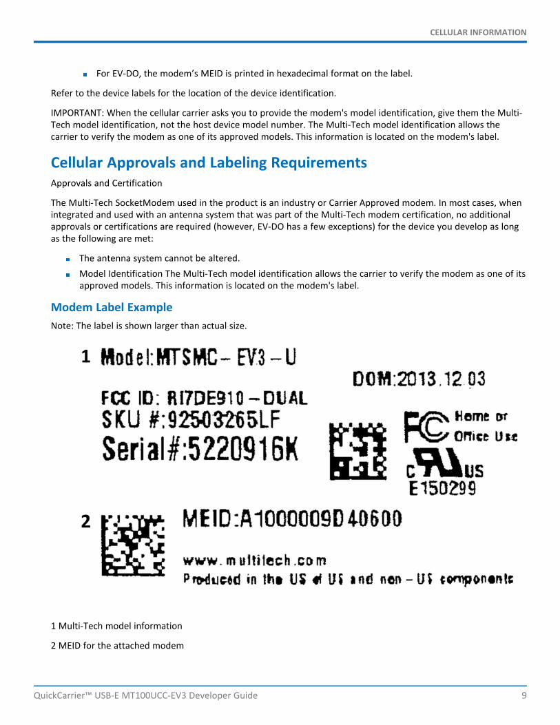
Modem Label ExampleNote: The label is shown larger than actual size.
1 Multi-Tech model information
2 MEID for the attached modem

CELLULAR INFORMATION
10 QuickCarrier™ USB-E MT100UCC-EV3 Developer Guide
1 Multi-Tech model information
2 Multi-Tech ordering part number
3 MEID for the attached modem

OEM INTEGRATION
QuickCarrier™ USB-E MT100UCC-EV3 Developer Guide 11
Chapter 4 – OEM IntegrationFCC Grant NotesThe OEM should follow all the grant notes listed below. Otherwise, further testing and device approvals may benecessary.
The antenna gain, including cable loss, for the radio you are incorporating into your product design must notexceed the requirements at 850 MHz and 1900 MHz as specified by the FCC grant for mobile operations and fixedmounted operations as defined in 2.1091 and 1.1307 of the FCC rules for satisfying RF exposure compliance. Poweroutput listed is conducted.
This device is a mobile device with respect to RF exposure compliance. The antenna(s) used for this transmittermust be installed to provide a separation distance of at least 20 cm from all persons, and must not be collocated oroperate in conjunction with any other antenna or transmitter except in accordance with FCC multi-transmitterproduct guidelines. Installers and end-users must be provided with specific information required to satisfy RFexposure compliance for installations and final host devices. (See note under Grant Limitations.) Compliance of thisdevice in all final host configurations is the responsibility of the Grantee.
Grant LimitationsThis device has been granted modular approval for mobile applications. Portable applications may require furtherRF exposure (SAR) evaluations. Examples of mobile devices include wireless routers, desktop computers, utilitymeters, etc. Examples of portable applications include devices such as a laptop, USB dongle, mobile phone, tabletPC, and any device that can be worn on the body during use.
Your final product with this embedded device may need to pass FCC Part 15B.
This device has not been evaluated or approved for simultaneous transmission. Any simultaneous transmissionconditions should be evaluated per the current FCC KDB 447498 requirements. Simultaneous transmissionrequirements for mobile devices are contained in Section 8.
KDB 447498 Section 8Transmitters and modules certified for mobile or portable exposure conditions and categorically excluded by §2.1091(c) can be incorporated in mobile host devices without further testing or certification when:
The closest separation among all simultaneous transmitting antennas is ≥ 20 cm;orThe antenna separation distance and MPE compliance boundary requirements that enable all simultaneoustransmitting antennas incorporated within the host to comply with MPE limits are specified in the applicationfiling of at least one of the certified transmitters incorporated in the host device. In addition, whentransmitters certified for portable use are incorporated in a mobile host device the antenna(s) must be ≥ 5 cmfrom all other simultaneous transmitting antennas. All antennas in the final product must be at least 20 cmfrom users and nearby persons.
If the host device requires further authorization, consult an accredited FCC laboratory for guidance.
FCC DefinitionsPortable: (§2.1093) — A portable device is defined as a transmitting device designed to be used so that theradiating structure(s) of the device is/are within 20 centimeters of the body of the user.

OEM INTEGRATION
12 QuickCarrier™ USB-E MT100UCC-EV3 Developer Guide
Mobile: (§2.1091) — A mobile device is defined as a transmitting device designed to be used in other than fixedlocations and to generally be used in such a way that a separation distance of at least 20 centimeters is normallymaintained between the transmitter’s radiating structure(s) and the body of the user or nearby persons.
Host LabelingThe following statements are required to be on the host label:
This device contains FCC ID: {Add the FCC ID of the specific device}This device contains equipment certified under IC ID: {Add the IC ID of the specific device}
For labeling examples, see Cellular Approvals and Labeling Requirements.
Carrier Specific InformationNotice for Devices that Use Aeris RadiosOne component of your device is a radio. A radio algorithm prevents your device from repeatedly attempting toconnect to the network when the radio:
Cannot establish a packet data connection orFails to access the application server.
When writing applications for your devices, ensure that your applications do not interfere with the radio'sconnection retry algorithm. If you fail to do so, Aeris might block network access for your devices.
After your devices reach the end of their commercial lifespan, you must remove them from the Aeris network. Todo so, remove power from the devices and remove their antennas. If your devices continue to attempt to registerwith the network after you cancel device subscriptions, Aeris can bill you for any traffic generated by thosedevices.
MultiTech Sprint Approved Device Requirements
Any changes to a Sprint approved MultiTech device circuit board or antenna system requires you to contact Sprintcertifications. Sprint will determine if additional testing is required due to modification of the approved devicecircuit board or antenna system.
All applications interacting with Sprint approved MultiTech devices must be written in a manner where they do notinterfere/ interrupt the Sprint HFA process or OMA-DM processes outlined in section labeled Telit OMA DMNotifications.
If the MultiTech device will be co-located with any other transmitters you will be required to submit your device toan FCC approved lab for additional FCC testing.
If the Sprint approved MultiTech device/circuit board is embedded into another device/circuit board be aware youwill be required to perform EMC and safety testing on your end device.
Sprint OMA DM NotificationsApplications should look for the following unsolicited OMA indications at all times:
#904 HFA Started
#905 PRL - Session started
#906 DC - Session started

OEM INTEGRATION
QuickCarrier™ USB-E MT100UCC-EV3 Developer Guide 13
#907 FUMO -Session started
If application sees one of these indications it should not attempt to issue commands, attempt data connection, orreset device until the OMA process is complete as indicated by additional #9XX OMA success or failure indicationsbelow.
If the device is in a data connection at the time a Network Initiated PRL, DC, or FUMO update alert message isreceived from Sprint, the radio may close the data connection and start OMA-DM process with a #9xx indication.When this occurs the application should not attempt to issue AT commands, attempt to start data connectionagain, or reset device in an attempt to regain control. Application should wait for a #9xx indication the process hascompleted before proceeding.
Be aware after the HFA process is successfully completed the radio will be reset. The radio may also reset afterother OMA functions.
Sprint #9XX OMA Unsolicited Indications
#900 DM Client Ready
Sprint Hands Free Activation HFA Notifications
#901 HFA Attempt #
#902 HFA Countdown Timer (seconds)
#904 HFA Started
#911 HFA Error - credential error
#912 HFA Error - unreachable server
#913 HFA Error - network error
#914 HFA Done - HFA success
#922 HFA Done - No profile received
#923 HFA Error – ETC
#924 HFA Cancelled
#DREL Data session release
Sprint Network Initiated Device Configuration (NIDC) or Client Initiated Device Configuration (CIDC)
#906 DC - Session started
#911 DC - Error - credential error
#912 DC - Error - unreachable server
#913 DC - Error - network error
#915 DC - Error - update fails for other reasons
#918 DC - Done - success
#924 DC - Cancelled - no profile received
#DREL Data session release

OEM INTEGRATION
14 QuickCarrier™ USB-E MT100UCC-EV3 Developer Guide
Sprint Network Initiated or Client Initiated Preferred Roaming List (NIPRL or CIPRL) Download
#905 PRL - Session started
#909 PRL - Done - PRL success
#910 PRL - Done - No PRL update
#911 PRL - Error - credential error
#912 PRL - Error - unreachable server
#913 PRL - Error - network error
#915 PRL - Error - update failed for other reasons
#DREL Data session release
Sprint Network Initiated (NI) or Client Initiated (CI) Firmware Update Management Object (FUMO)Notifications
#907 FUMO - Firmware DM session started or started again until no more updates are available
#911 FUMO - credential error
#912 FUMO - unreachable server
#913 FUMO - network error
#915 FUMO – update fails with other reasons
#916 FUMO - Firmware done, no firmware update
#919 FUMO - Firmware downloaded successfully
#920 FUMO - Firmware download progress (percent)
#921 FUMO - Firmware download start
#921 FUMO - Firmware size get from the OMA-DM server (byte)
#929: 200 FUMO - Firmware Update Success
#929: 402 FUMO - Firmware corrupted , CRC error
#929: 403 FUMO - Firmware package mismatch
#929: 404 FUMO - Firmware signature failed
#929: 406 FUMO - Firmware update authentication failed
#929: 410 FUMO - Firmware update General Error
#930 FUMO - Firmware reporting firmware update result to server
#DREL Data session release
Sprint Additional Network Initiated Alert Indications (NIA Retry)
#926 NIA - NIA retry start
#927 NIA - Notification done with no NIFA information
#928 NIA - NIA digest mismatch error

OEM INTEGRATION
QuickCarrier™ USB-E MT100UCC-EV3 Developer Guide 15
OMA-DM Commands
These commands are available after the unsolicited indication #900 appears, which means DM client is ready.
AT#OMADMSVADDR=<URL> Set OMA-DM server address (defaulthttps://oma.ssprov.sprint.com/oma)
AT#OMADMSVADDR? Read OMA-DM server address
AT#OMADMSVPORT=<port#> Set OMA-DM server (default 443)
AT#OMADMSVPORT? Read OMA-DM server
AT#OMADMPROXY=<port#>,<URL> Set OMA-DM proxy server port/URL (defaulthttp://oma.ssprov.sprint.com:80)
AT#OMADLPROXY=<port#>,<URL> Set OMA-DL Proxy DL Server Port URL (defaulthttp://oma.ssprov.sprint.com:80)
AT#OMADMCEN=<onoff> Set OMA-DM Client feature; Disable=0, Enable=1
Important: Never deploy devices with AT#OMADMCEN=0. ManyOMA commands result in error if OMADMCEN is set to 0.
AT#OMADMCEN? Query the current OMA-DM client status
AT#OMADMCEN=? Query OMA-DM available values
AT+OMADM=(onoff) Set OMA-DM Client Initiated Device Configuration; Disable=0, Enable=1,Initiate=2
AT+OMADM=? Query OMA-DM Client Initiated Device setting
AT+PRL=<onoff> Set OMA-DM CIPRL Session; Disable=0, Enable=1, Initiate=2
AT+PRL=? Query OMA-DM CIPRL Session setting
AT+FUMO= Set OMA-DM FUMO enable parameter; Disable=0, Enable=1, Initiate=2
AT+FUMO=? Query OMA-DM FUMO parameter
AT#HFA Initiate Sprint Hands Free Activation (HFA)
AT#HFACANCEL Cancel Sprint Hands Free Activation (HFA) DM Session
AT$RTN=xxxxxx HFA reset (after device reboot HFA will occur) xxxxxx= SPC or MSL.Note: May not work with all firmware versions.
AT#SPRTN=xxxxxx After device reboot HFA will occur xxxxxx= SPC or MSL
AT#DCCANCEL Cancel Device Configuration (DC) Session
AT#PRLCANCEL Cancel Preferred Roaming List (PRL) Session
AT$PRL? Query Preferred Roaming List (PRL) ID #
AT#FUMOCANCEL Cancel Firmware Update Management Object (FUMO) session.
Sprint Successful Indications
Typical Successful HFA SessionIndications
Alternate Successful HFA SessionIndications
Typical Successful FUMO SessionIndications With firmware update
#900 #900 #907

OEM INTEGRATION
16 QuickCarrier™ USB-E MT100UCC-EV3 Developer Guide
Typical Successful HFA SessionIndications
Alternate Successful HFA SessionIndications
Typical Successful FUMO SessionIndications With firmware update
#904 #904 #921
#919 #914 #921: 572 Bytes
#905 #905 #920:23
#909 #910 #920:100
#907 #900 New firmware installing
#916 #900
#900 #930
#907
#929:200
Typical Successful FUMOSession Indications withoutFirmware Update
Typical Successful PRL SessionsIndications
Typical Successful DC Session Indications
#907 #905 #906
#916 #909 #918
or
#905
#910

SAFETY WARNINGS
QuickCarrier™ USB-E MT100UCC-EV3 Developer Guide 17
Chapter 5 – Safety WarningsRadio Frequency (RF) SafetyDue to the possibility of radio frequency (RF) interference, it is important that you follow any special regulationsregarding the use of radio equipment. Follow the safety advice given below.
Operating your device close to other electronic equipment may cause interference if the equipment isinadequately protected. Observe any warning signs and manufacturers’ recommendations.Different industries and businesses restrict the use of cellular devices. Respect restrictions on the use ofradio equipment in fuel depots, chemical plants, or where blasting operations are in process. Followrestrictions for any environment where you operate the device.Do not place the antenna outdoors.Switch OFF your wireless device when in an aircraft. Using portable electronic devices in an aircraft mayendanger aircraft operation, disrupt the cellular network, and is illegal. Failing to observe this restrictionmay lead to suspension or denial of cellular services to the offender, legal action, or both.Switch OFF your wireless device when around gasoline or diesel-fuel pumps and before filling your vehiclewith fuel.Switch OFF your wireless device in hospitals and any other place where medical equipment may be in use.
Interference with Pacemakers and Other Medical DevicesPotential interferenceRadio frequency energy (RF) from cellular devices can interact with some electronic devices. This iselectromagnetic interference (EMI). The FDA helped develop a detailed test method to measure EMI of implantedcardiac pacemakers and defibrillators from cellular devices. This test method is part of the Association for theAdvancement of Medical Instrumentation (AAMI) standard. This standard allows manufacturers to ensure thatcardiac pacemakers and defibrillators are safe from cellular device EMI.
The FDA continues to monitor cellular devices for interactions with other medical devices. If harmful interferenceoccurs, the FDA will assess the interference and work to resolve the problem.
Precautions for pacemaker wearersIf EMI occurs, it could affect a pacemaker in one of three ways:
Stop the pacemaker from delivering the stimulating pulses that regulate the heart's rhythm.Cause the pacemaker to deliver the pulses irregularly.Cause the pacemaker to ignore the heart's own rhythm and deliver pulses at a fixed rate.
Based on current research, cellular devices do not pose a significant health problem for most pacemaker wearers.However, people with pacemakers may want to take simple precautions to be sure that their device doesn't causea problem.
Keep the device on the opposite side of the body from the pacemaker to add extra distance between thepacemaker and the device.Avoid placing a turned-on device next to the pacemaker (for example, don’t carry the device in a shirt orjacket pocket directly over the pacemaker).

SAFETY WARNINGS
18 QuickCarrier™ USB-E MT100UCC-EV3 Developer Guide
Vehicle SafetyWhen using your device in a vehicle:
Do not use this device while driving.Respect national regulations on the use of cellular devices in vehicles.If incorrectly installed in a vehicle, operating the wireless device could interfere with the vehicle’selectronics. To avoid such problems, use qualified personnel to install the device. The installer should verifythe vehicle electronics are protected from interference.Using an alert device to operate a vehicle’s lights or horn is not permitted on public roads.UL evaluated this device for use in ordinary locations only. UL did NOT evaluate this device for installation ina vehicle or other outdoor locations. UL Certification does not apply or extend to use in vehicles or outdoorapplications.
Device MaintenanceWhen maintaining your device:
Do not attempt to disassemble the device. There are no user serviceable parts inside.Do not misuse the device. Follow instructions on proper operation and only use as intended. Misuse couldmake the device inoperable, damage the device and/or other equipment, or harm users.Do not apply excessive pressure or place unnecessary weight on the device. This could result in damage tothe device or harm to users .Do not use this device in explosive or hazardous environments unless the model is specifically approved forsuch use. The device may cause sparks. Sparks in explosive areas could cause explosion or fire and mayresult in property damage, severe injury, and/or death.Do not expose your device to any extreme environment where the temperature or humidity is high. Suchexposure could result in damage to the device or fire.Do not expose the device to water, rain, or spilled beverages. It is not waterproof. Exposure to liquids couldresult in damage to the device.Do not place the device alongside computer discs, credit or travel cards, or other magnetic media. Theinformation contained on discs or cards may be affected by the device.Using accessories, such as antennas, that MultiTech has not authorized or that are not compliant withMultiTech's accessory specifications may invalidate the warranty.
If the device is not working properly, contact MultiTech Technical Support.
Handling PrecautionsTo avoid damage due to the accumulation of static charge, use proper precautions when handling any cellulardevice. Although input protection circuitry has been incorporated into the devices to minimize the effect of staticbuild-up, use proper precautions to avoid exposure to electronic discharge during handling and mounting thedevice.
User ResponsibilityRespect all local regulations for operating your wireless device. Use the security features to block unauthorized useand theft.

REGULATORY COMPLIANCE STATEMENTS
QuickCarrier™ USB-E MT100UCC-EV3 Developer Guide 19
Chapter 6 – Regulatory Compliance Statements47 CFR Part 15 Regulation Class B DevicesThis equipment has been tested and found to comply with the limits for a Class B digital device, pursuant to part15 of the FCC Rules. These limits are designed to provide reasonable protection against harmful interference in aresidential installation. This equipment generates, uses, and can radiate radio frequency energy and, if not installedand used in accordance with the instructions, may cause harmful interference to radio communications. However,there is no guarantee that interference will not occur in a particular installation. If this equipment does causeharmful interference to radio or television reception, which can be determined by turning the equipment off andon, the user is encouraged to try to correct the interference by one or more of the following measures:
Reorient or relocate the receiving antenna.Increase the separation between the equipment and receiver.Connect the equipment into an outlet on a circuit different from that to which the receiver is connected.Consult the dealer or an experienced radio/TV technician for help.
Warning: Changes or modifications to this unit not expressly approved by the party responsible for compliancecould void the user’s authority to operate the equipment.
Industry Canada Class B NoticeThis Class B digital apparatus meets all requirements of the Canadian Interference-Causing Equipment Regulations.
Cet appareil numérique de la classe B respecte toutes les exigences du Reglement Canadien sur le matérielbrouilleur.
This device complies with Industry Canada license-exempt RSS standard(s). The operation is permitted for thefollowing two conditions:
1. the device may not cause interference, and2. this device must accept any interference, including interference that may cause undesired operation of
the device.
Le présent appareil est conforme aux CNR d'Industrie Canada applicables aux appareils radio exempts de licence.L'exploitation est autorisée aux deux conditions suivantes:
1. l'appareil ne doit pas produire de brouillage, et2. l’appareil doit accepter tout brouillage radioélectrique subi, même si le brouillage est susceptible d’en
compromettre le fonctionnement.
Restriction of the Use of Hazardous Substances (RoHS)
Multi-Tech Systems, Inc.
Certificate of Compliance
2011/65/EU

REGULATORY COMPLIANCE STATEMENTS
20 QuickCarrier™ USB-E MT100UCC-EV3 Developer Guide
Multi-Tech Systems, Inc. confirms that its embedded products comply with the chemical concentration limitationsset forth in the directive 2011/65/EU of the European Parliament (Restriction of the use of certain HazardousSubstances in electrical and electronic equipment - RoHS).
These MultiTech products do not contain the following banned chemicals1:
Lead, [Pb] < 1000 PPMMercury, [Hg] < 1000 PPMHexavalent Chromium, [Cr+6] < 1000 PPMCadmium, [Cd] < 100 PPMPolybrominated Biphenyl, [PBB] < 1000 PPMPolybrominated Diphenyl Ether, [PBDE] < 1000 PPM
Environmental considerations:
Moisture Sensitivity Level (MSL) =1Maximum Soldering temperature = 260C (in SMT reflow oven)
1Lead usage in some components is exempted by the following RoHS annex, therefore higher lead concentrationwould be found in some modules (>1000 PPM);
- Resistors containing lead in a glass or ceramic matrix compound.

MT100UCC-EV3 MODEL OVERVIEW
QuickCarrier™ USB-E MT100UCC-EV3 Developer Guide 21
Chapter 7 – MT100UCC-EV3 Model OverviewSpecificationsMT100UCC-EV3
Category Description
General
Performance 3G EV-DO
FrequencyBands
Dual band 800/1900 MHz
Speed
Data Speed 3.1 Mbps downlink, 1.8 Mbps uplink
Interface
USB USB 2.0 high speed compliant
Driver support
Operatingsystems
Drivers are available for Windows and Linux operating systems. You can downloaddrivers from the Multi-Tech Installation Resources website atwww.multitech.com/setup/product.go
Physical Description
Weight 1.536 oz
43.5 g
Dimensions 3.15 in x 1.375 in
80.010 mm x 34.93 mm
Connectors
Antenna All models have surface mount UFL antenna connectors.
Environment
OperatingTemperature
-40° C to +85° C
StorageTemperature
-40° C to +85° C
Humidity 20% to 90% non-condensing
Power Requirements

MT100UCC-EV3 MODEL OVERVIEW
22 QuickCarrier™ USB-E MT100UCC-EV3 Developer Guide
Category Description
OperatingVoltage
Supply range: 4.75 V to 5.25 V
1.1A nominal current
Device may be damaged if voltage exceeds 5.5 V
Input Power USB bus powered
SMS
Point-to-Point messaging
Mobile-Terminated SMS
Mobile-Originated SMS
Certifications, Compliance, Warranty
EMCCompliance
FCC Part 15 Class B
RadioCompliance
FCC Part 22
FCC Part 24
SafetyCompliance
UL 60950-1 2nd edition
cUL 60950-1 2nd edition
IEC 60950-1 2nd edition
NetworkCompliance
Verizon
Sprint
Aeris
Warranty 2 years
Note: The radio's performance may be affected at the temperature extremes. This is considered normal. The radiois designed to automatically fallback in class and reduces transmitter power to avoid damage to the radio. There isno single cause for this function. Rather, it is the result of an interaction of several factors, such as the ambienttemperature, the operating mode and the transmit power.
You may need to reduce the temperature range if airflow is limited around the cellular radio. Test and verify thetemperature range if the QuickCarrier USB-E is designed into an enclosed chassis.

MT100UCC-EV3 MODEL OVERVIEW
QuickCarrier™ USB-E MT100UCC-EV3 Developer Guide 23
Mechanical drawing

MT100UCC-EV3 MODEL OVERVIEW
24 QuickCarrier™ USB-E MT100UCC-EV3 Developer Guide
Power Draw MT100UCC-EV3-GPCellular call boxconnection no data(amps)
Measured current(amps) at maximumpower
Peak TX (amps) Total inrush chargemeasured inMilliCoulombs (mC)
5 volts
US Cellular 800Mhz 0.319 0.817 0.868 2.60
US PCS 1900MHz 0.326 0.843 0.896 2.60
Note: Multi-Tech Systems, Inc. recommends that you incorporate a 10% buffer into the power source whendetermining product load.
Peak Tx: The peak current during a CDMA connection transmitting data at max power.
Maximum Power: The continuous current during maximum data rate with the radio transmitter at maximumpower.
Inrush Charge: The total inrush charge at power on.
Powering Down Your DeviceCAUTION: Failing to properly power down the device before removing power may corrupt your device's filesystem.
To properly power down your device, use the following sequence :
1. Issue the AT#SHDN command.2. Wait 30 seconds.3. Power off or disconnect power.
Pinout SpecificationsPins Signal Name Logic Level Voltage I/O Description
JP2-1 VCC 5.0 PWR DC input power
JP2-2 USB DN 3.3 I/O USB data
JP2-3 USB DP 3.3 I/O USB data
JP2-4 GND GND GND Ground
APPLICATION NOTES
QuickCarrier™ USB-E MT100UCC-EV3 Developer Guide 25
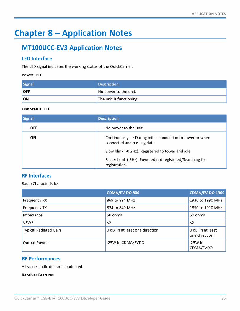
Chapter 8 – Application NotesMT100UCC-EV3 Application NotesLED InterfaceThe LED signal indicates the working status of the QuickCarrier.
Power LED
Signal Description
OFF No power to the unit.
ON The unit is functioning.
Link Status LED
Signal Description
OFF No power to the unit.
ON Continuously lit: During initial connection to tower or whenconnected and passing data.
Slow blink (-0.2Hz): Registered to tower and idle.
Faster blink (-3Hz): Powered not registered/Searching forregistration.
RF InterfacesRadio Characteristics
CDMA/EV-DO 800 CDMA/EV-DO 1900
Frequency RX 869 to 894 MHz 1930 to 1990 MHz
Frequency TX 824 to 849 MHz 1850 to 1910 MHz
Impedance 50 ohms 50 ohms
VSWR <2 <2
Typical Radiated Gain 0 dBi in at least one direction 0 dBi in at leastone direction
Output Power .25W in CDMA/EVDO .25W inCDMA/EVDO
RF PerformancesAll values indicated are conducted.
Receiver Features

APPLICATION NOTES
26 QuickCarrier™ USB-E MT100UCC-EV3 Developer Guide
Category Description
CDMA 1xRTT US Cellular 800 (Verizon)sensitivity
Typical better than < -108 dBm
CDMA 1xRTT US PCS 1900 (Sprint)sensitivity
Typical better than < -108 dBm
EV-DO 1x Rev 0 US Cellular 800 (Verizon)sensitivity
Typical better than < -109 dBm
EV-DO 1x Rev 0 US PCS 1900 (Sprint)sensitivity
Typical better than < -109 dBm
Transmitter Features
Category Description
Maximum output power (CDMA 1x RTT& EV-DO 1x Rev 0/Rev A)
+24 dBm ± 1 dBm
RF Connection and Antenna
The RF connector on the QuickCarrier is a UFL standard type. See Chapter 1 for Antenna details.

CONFIGURING AND COMMUNICATING WITH YOUR DEVICE
QuickCarrier™ USB-E MT100UCC-EV3 Developer Guide 27
Chapter 9 – Configuring and Communicating withYour Device
Interacting with Your Device OverviewThis section describes how to use AT commands to interact with your device. Using terminal software such asKermit, you can issue AT commands to communicate with and configure your modem. The AT commands let youestablish, read and modify device parameters and help you control how the device operates. This sectiondocuments basic interactions with your device, such as verifying signal strength and network registrations, sendingand reading SMS text messages, and sending and receiving data.
Generally, USB modems are used as unintelligent bit pipes. In Windows, this means you create a dial-up networkconnection that uses the Windows IP stack to use the modem to create a PPP connection to the cellular network.The modem is assigned an IP address from the cellular carrier. This connection provides Internet access and is thebasis for TCP/IP communication for sending and receiving email, creating TCP/UDP Sockets, or putting and gettingfiles from an FTP server.
In Linux, PPPD is used to dial the modem and create the connection to the cellular TCP/IP network. This providesInternet access for sending and receiving email, creating TCP/UDP Sockets, or putting and getting files from an FTPserver.
Before Using the DeviceBefore using the device:
Install any drivers. Refer to the separate driver installation guide for your device.Power up your device and ensure it is connected to your computer that issues AT commands.Install terminal software that can communicate with the device, such as HyperTerminal, Tera Term, Kermit,or Putty.
Using Command Mode and Online Data ModeModems have two operation modes, command and online data. After power up, the modem is in command modeand ready to accept AT commands.
Use AT commands to communicate with and configure your modem. These commands establish, read, and modifydevice parameters and control how the modem works. The device also generates responses to AT commands thathelp determine the modem’s current state.
If the modem is in online data mode, it only accepts the Escape command (+++).
To send the modem AT Commands from terminal emulation software, set the software to match the modem’sdefault data format, which is:
Speed: 115,200 bpsData bits: 8Parity: noneStop bit: 1Flow control: hardware

CONFIGURING AND COMMUNICATING WITH YOUR DEVICE
28 QuickCarrier™ USB-E MT100UCC-EV3 Developer Guide
To confirm communication with the device:
Type AT and press Enter.
If the device responds with OK, it is properly communicating.
Verifying Signal StrengthTo verify the device signal strength, enter:
AT+CSQ
The command indicates signal quality, in the form:
+CSQ: <rssi>,<ber>
Where:
<rssi> Received signal strength indication.
0 (-113) dBm or less
1 (-111) dBm
2-30 (-109) dBm - (-53) dBm / 2 dBm per step
31 (-51) dBm or greater
99 Not known or not detectable
<ber> Bit error rate, in percent
0 Less than 0.2%
1 0.2% to 0.4%
2 0.4% to 0.8%
3 0.8% to 1.6%
4 1.6% to 3.2%
5 3.2% to 6.4%
6 6.4% to 12.8%
7 More than 12.8%
99 Not known or not detectable
Note: Signal strength of 10 or higher is needed for successful packet data sessions.
ExampleA example response to AT+CSQ:

CONFIGURING AND COMMUNICATING WITH YOUR DEVICE
QuickCarrier™ USB-E MT100UCC-EV3 Developer Guide 29
+CSQ: 15,1
Sending and Receiving DataConnecting Device to TCP Server as TCP Client
1. Bring up Data Connection Using Internal IP stackEnter:AT#SGACT=1,1The device responds with the IP Address the cellular provider assigned to the device on connection,followed by OK. For example:#SGACT: 25.194.185.116OK
2. Create Client Connection to TCP Server on Port 500Enter:AT#SD=1,0,500,"###.##.###.##"where ###.##.###.## is the TCP server IP Address.The device responds with OK. You can now send or receive data without entering additional commands.
Closing the Socket and the ConnectionTo close the socket:
Enter the escape sequence:+++
To close Socket 1, enter:AT#SH=1
The device responds with OK.
To close the data connection:
Enter:AT#SGACT=1,0
The device responds with OK.
Configuring Device as UDP Listener to Accept UDP Client Connections
To configure the device as a UDP client:
1. Check signal strength.Enter:AT+CSQ
2. Verify device is registered on the cellular network.Enter:AT+CREG?Should return:
3. Configure socket parametersEnter:
CONFIGURING AND COMMUNICATING WITH YOUR DEVICE
30 QuickCarrier™ USB-E MT100UCC-EV3 Developer Guide
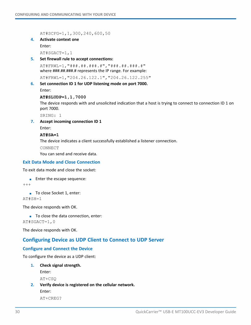
AT#SCFG=1,1,300,240,600,504. Activate context one
Enter:AT#SGACT=1,1
5. Set firewall rule to accept connections:AT#FRWL=1,"###.##.###.#","###.##.###.#"where ###.##.###.# represents the IP range. For example:AT#FRWL=1,"204.26.122.1","204.26.122.255"
6. Set connection ID 1 for UDP listening mode on port 7000.Enter:AT#SLUDP=1,1,7000The device responds with and unsolicited indication that a host is trying to connect to connection ID 1 onport 7000.SRING: 1
7. Accept incoming connection ID 1Enter:AT#SA=1The device indicates a client successfully established a listener connection.CONNECTYou can send and receive data.
Exit Data Mode and Close ConnectionTo exit data mode and close the socket:
Enter the escape sequence:+++
To close Socket 1, enter:AT#SH=1
The device responds with OK.
To close the data connection, enter:AT#SGACT=1,0
The device responds with OK.
Configuring Device as UDP Client to Connect to UDP ServerConfigure and Connect the DeviceTo configure the device as a UDP client:
1. Check signal strength.Enter:AT+CSQ
2. Verify device is registered on the cellular network.Enter:AT+CREG?

CONFIGURING AND COMMUNICATING WITH YOUR DEVICE
QuickCarrier™ USB-E MT100UCC-EV3 Developer Guide 31
Should return:3. Configure socket parameters
Enter:AT#SCFG=1,1,300,240,600,50
4. Activate context oneEnter:AT#SGACT=1,1
5. Create UDP connection to Server portEnter:AT#SD=1,1,####,"###.##.###.##"where #### is the server port and ###.##.###.## is the IP number.
The device responds with OK, which indicates a successful connection. You can send and receive data through thesocket connection.
Exit Data Mode and Close ConnectionTo exit data mode and close the socket:
Enter the escape sequence:+++
To close Socket 1, enter:AT#SH=1
The device responds with OK.
To close the data connection, enter:AT#SGACT=1,0
The device responds with OK.
Transferring FTP File to FTP Server
To connect to FTP server and upload files:
1. Check signal strength.Enter:AT+CSQ
2. Verify device is registered on the cellular network.Enter:AT+CREG?Should return:
3. Activate context oneEnter:AT#SGACT=1,1
4. Set FTP operations timeout to 10 secondsEnter:AT#FTPTO=1000

CONFIGURING AND COMMUNICATING WITH YOUR DEVICE
32 QuickCarrier™ USB-E MT100UCC-EV3 Developer Guide
5. Configure FTP server IP address with username and password.Enter:AT#FTPOPEN="###.##.###.#","username","password",0where ###.##.###.# is the IP address and the username and password for the FTP server.
6. Configure file transfer type.Enter:AT#FTPTYPE=#where # is 0 for binary or 1 for ASCII.
7. Enter the file name to be sent to the FTP server and initiate connection.Enter:AT#FTPPUT="file.txt"The device responds with:CONNECT
8. Send the file through the device.
Closing the FTP Data ConnectionWhen you finish sending the file:
1. Enter the escape sequence.Enter:+++The device responds with:NO CARRIER
2. Close the FTP connection.Enter:AT#FTPCLOSE
3. Close the PPP data connection.Enter:AT#SGACT=1,0The device responds with OK.
Downloading File from FTP Server
To connect to an FTP server and download files:
1. Check signal strength.Enter:AT+CSQ
2. Verify device is registered on the cellular network.Enter:AT+CREG?Should return:
3. Activate context oneEnter:AT#SGACT=1,1

CONFIGURING AND COMMUNICATING WITH YOUR DEVICE
QuickCarrier™ USB-E MT100UCC-EV3 Developer Guide 33
4. Set FTP operations timeout to 10 secondsEnter:AT#FTPTO=1000
5. Configure FTP server IP address with username and password.Enter:AT#FTPOPEN="###.##.###.#","username","password",0where ###.##.###.# is the IP address and the username and password for the FTP server.
6. Configure file transfer type.Enter:AT#FTPTYPE=#where # is 0 for binary or 1 for ASCII.
7. If required, change the working directory to "folder1".Enter:AT#FTPCWD="folder1"
8. Enter the file name.Enter:AT#FTPGET="filename.txt"where filename.txt is the file you want to download.The device responds with:CONNECTThe file is received through the device. The device responds with:NO CARRIERThe data connection closes automatically when the file sending ends.
Closing the FTP Data ConnectionWhen you finish sending the file:
1. Close the FTP connection.Enter:AT#FTPCLOSE
2. Close the PPP data connection.Enter:AT#SGACT=1,0The device responds with OK.
Reading, Writing and Deleting MessagesReading Text Messages
To read a text message in text mode:
1. Put the device in text mode.Enter:AT+CMGF=1
2. Read message.

CONFIGURING AND COMMUNICATING WITH YOUR DEVICE
34 QuickCarrier™ USB-E MT100UCC-EV3 Developer Guide
Enter:AT+CMGR=1
Example response:
+CMGR: "REC UNREAD","+10001112222z`z","","13/09/05,13:39:40-20"How are you?OK
Where 0001112222 is the phone number.
Writing Text MessagesTo send a text message in text mode:
1. Put the device in text mode.Enter:AT+CMGF=1The device responds.OK
2. Enter the recipient's number and your message.Enter:AT+CMGS="##########">Your message here
where ########## is the recipient's number.3. Send the message.
Enter CTRL+Z.The device responds:+CMGS: #OKwhere # is the reference number of the sent message.
For example:
AT+CMGF=1OKAT+CMGS="0001112222"> How are you? <CTRL+Z to send>+CMGS: 255OK
Where 0001112222 is the phone number.
Deleting Messages
To delete one text message, enter:
AT+CMGD=I,#
where I is the index in the select storage and # is the delflag option. Enter:
0 Deletes message in the specified index.

CONFIGURING AND COMMUNICATING WITH YOUR DEVICE
QuickCarrier™ USB-E MT100UCC-EV3 Developer Guide 35
1 Deletes all read messages. Leaves unread messages and stored device-originated messages.
2 Deletes all read and sent device-originated messages. Leaves unread messagesand unsent device-originated messages.
3 Deletes all read messages and sent and unsent device-orginated messages.Leaves unread messages.
4 Deletes all messages.
For example:
AT+CMGD=1 (delete message at index 1)AT+CMGD=2 (delete message at index 2 )AT+CMGD=1,0AT+CMGD=1,1AT+CMGD=1,2AT+CMGD=1,3AT+CMGD=1,4