Embed Size (px)
Citation preview

1

R. C. Tronics Incorporated2573 East Kercher RoadGoshen, Indiana 46528Toll Free 1-866-457-7790
Phone 1-574-642-3857Fax 1-574-642-3858Http://www.rctronics.com
RCT-01414 Plug-In-Play Bus Power Center CenterSame Features as our RCT-00786 Terminal Strip Bus Power Center
All Inputs and Outputs are Monitored with LEDs, makes Trouble-shooting a visual event.
Twenty-Four, Fuse Protected Power Relays Provide +12 VDC @ 20 Ampere For All Loads.
Electric Door Operator with Inputs to Limit Door Travel.
Latching Inputs for ADA and Passenger Stop Request.
ADA, Vehicle Secure System, Provides Output for Chair Lift, Locks Vehicle Shift Lever, Interfaces with Ford & Chevy Chassis.
ADA Information Panel, Displays all Inputs and Outputs.
Rear Door Unlock, Prevents Engine Start-Up if not Unlocked.
Information Indicators, Lift Door, ADA Stop, Passenger Stop, Egress Window, Rear Door and Electric Door Open.
Size 16.5” x 10.5” x 2.5” Deep / Weight 10 lbs.
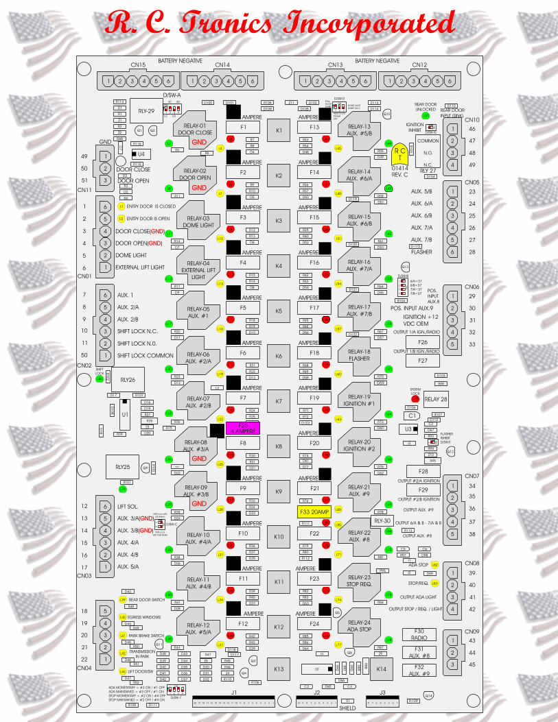
CN11-49 Battery Negative
CN11-50 Command “Door Close”
CN11-51 Command “Door Open”
CN01-01 Limit Switch “Entry Door Is Closed”
CN01-02 Limit Switch “Entry Door Is Open”
CN01-03 Motor Output “Door Close”
CN01-04 Motor Output “Door Open”
CN01-05 12 VDC Output “Dome Light”
CN01-06 12 VDC Output “External Lift Light”
CN02-07 12 VDC Output “Aux. 1”
CN02-08 12 VDC Output “Aux. 2/A”
CN02-09 12 VDC Output “Aux. 2/B”
CN02-10 Dry Contact “Shift Lock”
CN02-11 Dry Contact “Shift Lock”
CN03-12 Output “ADA Lift Enable”
CN03-13 12 VDC Output “Aux. 3/A”
CN03-14 12 VDC Output “Aux. 3/B”
CN03-15 12 VDC Output “Aux. 4/A”
CN03-16 12 VDC Output “Aux. 4/B”
CN03-17 12 VDC Output “Aux. 5/A”
CN04-18 Limit Switch “Rear Door Switch”
CN04-19 Limit Switch “Egress Windows”
CN04-20 Limit Switch “Park Brake Switch”
CN04-21 Limit Switch “Transmission In Park”
CN04-22 Limit Switch “Lift Door Switch”
Normally Open and Normally Close Contacts available, select with Sw2.Green LED shows “Shift Lock Enabled”
Sw1 selects a battery negative orbattery positive at CN03-12. GreenLED shows “ADA Lift Enabled”
Normally Open and Normally Close Contacts available, select with Sw3.Green LED shows “Rear Door Unlocked”
CN10-46 Limit Switch “Rear Door Unlocked” (sink)
CN10-47 Dry Contact “Engine Start”
CN10-48 Dry Contact “Engine Start”
CN05-23 12 VDC Output “Aux. 5/B”
CN05-24 12 VDC Output “Aux. 6/A”
CN05-25 12 VDC Output “Aux. 6/B”
CN05-26 12 VDC Output “Aux. 7/A”
CN05-27 12 VDC Output “Aux. 7/B”
CN05-28 12 VDC Output “Flasher”
CN06-29 Input 12 VDC @ .14 ampere “Aux. 8”
CN06-30 Input 12 VDC @ .14 ampere “Aux. 9”
CN06-31 Input 12 VDC @ .35 ampere “Ignition”
CN06-32 12 VDC Output “Ignition”
CN06-33 12 VDC Output “Ignition”
CN07-34 12 VDC Output “Ignition”
CN07-35 12 VDC Output “Ignition”
CN07-36 12 VDC Output “Aux. 8”
CN07-37 12 VDC Output “6/A, 6/B, 7/A, 7/B”
CN07-38 12 VDC Output “Aux. 9”
CN08-39 Push Button Input “ADA Stop Request” (sink)
CN08-40 Push Button Input “Stop Request” (sink)
CN08-41 12 VDC Output “ADA Light”
CN08-42 12 VDC Output “Stop Request Light”
CN09-43 12 VDC Output “Battery”
CN09-44 12 VDC Output “Battery”
CN09-45 12 VDC Output “Battery”
J1 & J2 to Switch Center. J3 to ADA Display
CN-15, CN14, CN13, CN12 with 6 each, or a total 24 pins to “Battery Negative”


R. C. Tronics, Incorporated 2573 East Kercher Road Goshen, Indiana 46528 Phone 1-574-642-3857 www.rctronics.com Fax 1-574-642-3858 1-866-457-7790 Email; [email protected]
RCT-786 Revision M
Changes From Revision L
Added R106 680 ohm, ¼ watt resistor from “system ignition” to anodes of D9 & D30. This modification “loads” the “REAR DOOR SWITCH”. (Problem, low band RF would cause the alarm buzzer to operate.)
Changed the oscillator U3 to operate continuously. Add D112, R107 and Q12 to operate the
“FLASHER”, relay 18. Installed D/SW. E. When this dip switch is in the “ON” position the switching action of relay #18 is inhibited.
Added D111, R108, Q11, D115 and D/SW.-F this addition will permit the buzzer to operate in
an alternating fashion any time the “ADA Stop Request Switch, (Terminal #39)” is taken to ground. Placing switch #1 (D/SW.F) in the “ON” position and placing switch #3 (D/SW.F) “OFF” will latch the buzzer on and can only be turned off by opening the “Lift Door, (Terminal #22)”. Reversing the switch positions will only permit buzzer alternating operation during the time a ground is placed on “ADA Stop Request Switch, (Terminal #39)”.
The buzzer will operate any time the “Stop Request Switch, (Terminal #40)” is taken to ground. Placing switch #4 (D/SW.F) in the “ON” position and placing switch #2 (D/SW.F) “OFF” will latch the buzzer on and can only be turned off by opening the “Entry Door Is Open, (Terminal #2)”. Reversing the switch positions will only permit buzzer operation during the time a ground is placed on “Stop Request Switch, (Terminal #40)”.
Added Relay-29, (G6CK-2114P-US-DC12) this modification will substitute one or both of the
limit switch inputs, “ENTRY DOOR IS CLOSED (Terminal #1)” and / or “ENTRY DOOR IS OPEN (Terminal #2)”. “Entry Door Is Closed”, can be substituted by closing SW.#1 and opening SW#2 on dip switch labeled “D/SW-A”. “Entry Door Is Open”, can be substituted be closing SW#3 and opening SW#4 on the same dip switch, “D/SW-A”. This dip switch is located in the upper left hand corner of the Bus Power Center, RCT-786.
Added Dip Switch, labeled D/SW-B, located upper right hand side of PCB-786 and the
addition of D119, D120, D121, D122, D115, R-109 AND Q13. We also renamed terminal #29 to +12 VDC Aux. #8, (was +12 VDC Clearance Light) and terminal #30 to +12 VDC Aux. #9, (was +12 VDC Brake OEM Light). We also renamed three outputs, terminal #36 Aux. #9, (was Brake Lights) and terminal #37 & #38 to Aux. #8, (was Clearance Lights). Switching D/SW-B, Switch #1 thru Switch #4 to the “ON” position will cause relay #22 to energize, providing an output to terminals #37 & #38. Switch #1 = Aux. #6/A terminal #24, Switch #2 = Aux. #6/B terminal #25, Switch #3 = Aux. #7/A terminal #26 and Switch #4 = Aux. #7/B terminal #27.
Switch nomenclature back lighting, which operated with the old clearance light input will now
operate with “+12 VDC OEM Ignition, (Terminal #31).
5

Added Dip Switch, D/SW-C. Switch #1 “ON” = Shift Lock with “Lift Switch”. Switch #2 “ON” = Shift Lock with “Park Brake”, terminal #20. This dip switch is located lower left hand side of PCB.
Added Dip Switch D/SW-D, locate upper right top of PCB. Switch #1 “ON” = “Entry Door
Open” is inoperable until “Transmission In Park” is present on terminal #21. Switch #2 “ON” = “Rear Door Switch” terminal #18 a ground here will cause the system to remain locked on. Removing system “+12 VDC OEM IGNITION” terminal #31 or shutting off the “MASTER SWITCH” will have no effect until the rear door is closed. Switch #3 “ON” = “Dome Light” (Relay #3) inhibit. Dome light will not operate when “Entry Door Is Closed”, terminal #1 ground is removed.
Added slider switch, SW3 to Rear Door Unlock, Rly .27. Provides either N.O or N.C. to
terminals #47 and #48.
6
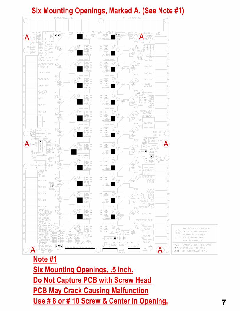
Note #1Six Mounting Openings, .5 Inch.
PCB May Crack Causing MalfunctionUse # 8 or # 10 Screw & Center In Opening.
Six Mounting Openings, Marked A. (See Note #1)
A A
AA
A A
Do Not Capture PCB with Screw Head
7

R. C. Tronics, Incorporated 2573 East Kercher Road Goshen, Indiana 46528 Phone 1-574-642-3857 www.rctronics.com Fax 1-574-642-3858 1-866-457-7790 Email; [email protected]
Bus Power Center, Revision M The BPC is a complete system consisting of main power center which houses twenty-four (24) power relays. A field replaceable, standard ATO fuse protects each. Three LED’s monitor each power relay. The red led depicts fuse status. A visible led indicates open fuse or circuit breaker. Amber led shows that control system is commanding power relay on. Lastly a green led shows 12 VDC is being supplied to the load, which is connected to the Power Center, via the numbered terminal strip. There are nine (10) signal inputs on the Power Center. All have amber LED’s, which are located at the terminal strip. All are taken to battery negative. A lighted led shows the input is grounded and will be referred to as “ON” in the following descriptions. On board is digital circuitry, which controls the operation of the “Lift Interlock System” Four conditions must be meant prior to allowing operation of this output. “LIFT SWITCH,” (Located on dash switch center, PCB-790 switch #3) 1st, “PARK BRAKE SWITCH”, On. (Terminal #20) 2nd, “TRANMISSION PARK”, On. (Terminal #21) 3rd, “Lift Door Switch”, (Terminal #22) Once these four conditions are present, a 12 VDC, rated at 4 Ampere (fuse F25) will be present at “LIFT SOL.”, (Terminal #12). In addition, when the “Park Brake Switch (Terminal #20)”, “Lift Door Switch” (Terminal #22) or “Lift Switch” is present the “Shift Lock Relay, (RLY-26)” will operate between terminal #10 and #11. A dip switch labeled “D/SWC” has two switches on it. Opening switch #1 will cause the “Lift Switch” not to operate the “Shift Lock Relay, (Rly-26)”, opening switch #2 will cause the “Park Brake, Terminal #20”, not to operate the “Shift Lock Relay, (Rly-26)”, This contact is interfaced with, shift lock so as not to permit the shift from being removed from “PARK”. There is a slide switch marked, “Shift Lock Switch, (Sw3)”. This switch is located on the PCB RCT-786. By selecting the “NC” you may interface with a Ford chassis series E & F. This is a “Green Wire”, cut and series. Placing the “Shift Lock Switch, (Sw3)” to NO you can interface with a Chevy chassis. A +12 VDC wired in parallel will lock the shift; this is a “Green/White wire. Additionally the system cannot be disabled until the lift is stored and the lift door is closed. There is a red led, L82,”System Lock”, located on the main RCT-786 Power Center which will not permit system shut down unless the lift is returned to it’s stored position and the lift door is closed. An optional led display is available which shows the status of all inputs and outputs associated with the “Lift Interlock System”, part number RCT-1010. This status indicator and be located at any location inside or outside the bus. NOTE: The above-described “Lift Interlock System” complies with the requirements of the American Disabilities ACT (ADA) Title 49 Code of Regulations
8

4th, “EGRESS WINDOW, (Terminal #19)”, a ground, here operates a warning buzzer. 5th, “REAR DOOR SWITCH, (Terminal #18)”, a ground, here operates the warning buzzer unless the “PARK BRAKE, (Terminal #20)” is taken to ground. There are four additional inputs. 6th, “ENTRY DOOR IS CLOSED, (Terminal #1)” a ground here from a Door Is Closed Limit Switch; limits the travel of the entry door by removing power to door actuator, terminal #3 and turning off the “Dome Lights, terminal #5, (RLY3)”. Note: With D/SWA, SW#1 to the “ON” position will provide a simulated input to turn off the “Dome Lights, (RLY-3)”. When this option is used you would normally place on D/SWA, SW#2 to the “OFF” position. This will cause the “Close Relay, (RLY-1) not to remove power from its terminal #3 on the RCT-786, Power Center. 7th, “ENTRY DOOR IS OPEN, (Terminal #2)” a ground here from a Door Is Open Limit Switch; limits the travel of the entry door by removing power to door actuator, terminal #4 providing a reset signal to the ADA stop request. Note: With D/SWA, SW#3 to the “ON” position will provide a simulated input to provide a reset signal to the ADA stop request. When this option is used you would normally place on D/SWA, SW#4 to the “OFF” position. This will cause the “Open Relay, (RLY-2) not to remove power from its terminal #4 on the RCT-786, Power Center. 8th, “STOP REQUEST, (Terminal #40)” a ground, here operates “Stop Request Relay, (RLY-24)” rated 12 vdc @ 20 ampere, present at terminal #42. The power relay will remain energized until “ENTRY DOOR IS OPEN, (Terminal #2)” is taken to ground. Note: A four position dip switch, labeled D/SWF is provided. By placing SW2 to the “ON” position will cause the stop request buzzer to operate in a continuous manner as long as the ground is provided to “Stop Request, (Terminal #40)”. Placing SW2 to the “OFF” and SW#4 to the “ON” position will cause the stop request buzzer to latch on until the “ENTRY DOOR IS OPEN, (Terminal #2”) is taken to ground. 9th, “ADA STOP REQUEST, (Terminal #39)” a ground, here operates “ADA Stop Request Relay, (RLY-23)” rated 12 vdc @ 20 ampere, present at terminal #41. ADA Stop Request Relay will remain energized until the “Lift Door Switch, (Terminal #22)” is taken to ground. Note: A four position dip switch, labeled D/SWF is provided. By placing SW3 to the “ON” position will cause the stop request buzzer to operate in a continuous manner as long as the ground is provided to “Stop Request, (Terminal #40)”. Placing SW3 to the “OFF” and SW#1 to the “ON” position will cause the stop request buzzer to latch on until the “ENTRY DOOR IS OPEN, (Terminal #2”) is taken to ground. 10th, “REAR DOOR UNLOCKED, (Terminal #46)” a ground, here operates relay, (RLT-27) which provides a either a N.O. or N.C. Contact which is selected by slider switch SW3 between Terminal #47 & Terminal #48. This is rated at 8 Ampere and permits engine start when Rear Door is Unlocked.
LIST OF TERMINAL ASSIGNMENTS
1. Entry Door Is Closed, to normally open contact, closes when door is closed. 2. Entry Door Is Open, to normally open contact, closes when door is open. 3. Door Closed, 12 vdc out, to operate door close actuator. (2-wire motor) 4. Door Open, 12 vdc out, to operate door open actuator. (2-wire motor)
9

5. Dome Lights, 12 vdc out, operates with, “Entry Door Is Open” & Switch 2, on PCB-790 6. External Lift Lights, 12 vdc out, operates with, “Lift Door Switch” (Terminal #22) 7. Aux. #1, 12 vdc out, operates with Switch #4 on PCB-790. 8. Aux. #2/A, 12 vdc out, operates with Switch #1 PCB-789. 9. Aux. #2/B, 12 vdc out, operates with Switch #1 PCB-789. 10. Shift Lock. Shift Lock Switch, Provides either N.O or N.C. Output. 11. Shift Lock. Shift Lock Switch, Provides either N.O or N.C. Output. 12. Lift Solenoid, 12 vdc, sends power or a battery negative to enable Chair Lift Control. 13. Aux. #3/A, 12 vdc out, operates with Switch #2 on PCB-789. 14. Aux. #3/B, 12 vdc out, operates with Switch #2 on PCB-789. 15. Aux. #4/A, 12 vdc out, operates with Switch #3 on PCB-789. 16. Aux. #4/B, 12 vdc out, operates with Switch #3 on PCB-789. 17. Aux. #5/A, 12 vdc out, operates with Switch #4 on PCB-789. 18. Rear Door Switch, N.O. contact to battery negative. (50 ma.) 19. Egress Windows, N.O. contact to battery negative. (50 ma.) 20. Park Switch Brake, N.O. contact to battery negative. (50 ma.) 21. Transmission Park, N.O. contact to battery negative. (50 ma.) 22. Lift Door Switch, N.O. contact to battery negative. (50 ma.) 23. Aux. #5/B, 12 vdc out, operates with Switch #4 on PCB-789. 24. Aux. #6/A, 12 vdc out, operates with Switch #5 on PCB-789. 25. Aux. #6/B, 12 vdc out, operates with Switch #5 on PCB-789. 26. Aux. #7/A, 12 vdc out, operates with Switch #6 on PCB-789. 27. Aux. #7/B, 12 vdc out, operates with Switch #6 on PCB-789. 28. Flasher, 12 vdc out, operates with Switch #7 on PCB-789, rate 1/second, and aprox. 29. +12 VDC OEM Clearance, input, 150 ma. operates Clearance Relay, terminal #37 30. +12 VDC OEM Brake Light, input, 150 ma., operates Brake Relay, terminal #36 31. +12 VDC OEM Ignition, input, 150 ma., operates Ignition relays, terminal #32, #33, #34, and #35. This input must be supplied to enable system. (Master Switch #8 on PCB-789 must be on to enable Bus Power Center. 32. Ignition, 12 vdc out, operates with OEM Ignition and Master Switch. 33. Ignition, 12 vdc out, operates with OEM Ignition and Master Switch. 34. Ignition, 12 vdc out, operates with OEM Ignition and Master Switch. 35. Ignition, 12 vdc out, operates with OEM Ignition and Master Switch. 36. Aux. #9, 12 vdc out, operates with OEM Brake, terminal #30. 37. Aux. #8, 12 vdc out, operates with OEM Clearance, terminal #29 38. Same as above, dual connection point. 39. ADA Stop Request, N.O. to battery negative. Signals wheel chair stop.(50 ma.) 40. Stop Request, N.O. to battery negative. Signals passenger exit. (50 ma.) 41. ADA Stop Request, 12 vdc out. 42. Stop Request, 12 vdc out. 43. Battery / Radio, 12 vdc out. 44. Battery #1, 12 vdc out. 45. Battery #2, 12 vdc out. 46. Rear Door Unlock, Input. (To battery negative, 12 VDC @ 30 ma.) 47. Rear Door is Unlocked, Engine Start. (12 VDC @ 8 Ampere) 48. Rear Door is Unlocked, Engine Start. (12 VDC @ 8 Ampere) The Power Center, RCT-786 is connected via a (thirty) 30-conductor cable. Which is routed to RCT-948 Dash Switch Panel or RCT-789 Dash Switch Panel, which houses eight switches, warning buzzer and connector J4, which provides six outputs, spare, plus ground they are as follows. 1. J4-1, Lift Door Light, sink @ 1 ampere. (From J1-8)
10

2. J4-2, ADA Stop Request, sink @ 1 ampere. (From J1-7) 3. J4-3, Egress Windows, sink @ 1 ampere. (From J1-6) 4. J4-4, Rear Door Light, sink @ 1 ampere. (From J1-5) 5. J4-5, Stop Request, sink @ 1 ampere. (From J1-4) 6. J4-6, Entry Door Light, sink @ 1 ampere. (From J1-3) 7. J4-7 Spare. (From J2-10) 8. J4-8 Ignition (+12 VDC Switched) (From J1-1) Switches on RCT-789 printed circuit board. 1. Aux. #2A/B Switch #1 2. Aux. #3A/B Switch #2 3. Aux. #4A/B Switch #3 4. Aux. #5A/B Switch #4 5. Aux. #6A/B Switch #5 6. Aux. #7A/B Switch #6 7. Flasher Switch #7 8. Master Switch #8 A second eight conductor is routed from RCT-789 to RCT-790. This printed circuit board houses four switches, which are as follows. 1. Entry Door Open and Door Close Switch #1 2. Dome Light Switch #2 3. Lift Switch #3 4. Aux. #1 Switch #4 Battery Negative should be connected to the 1/4 x 20 stud mounted to top center of RCT-786. Conductor should be large enough to carry all currents to be imposed upon it. There are eighteen terminal openings, which may be used for returns from circuit loads. The +12 VDC supply conductor should be mounted to center buss bar and connected to 1/4 x 20 stud provided. This conductor should be large enough to carry the total current of all connected loads. The size of power center, 2.5 deep x 16.5 bottom/top x 10.5 left/right weight 9 lb. Bus Power Center total weight including front switch assembly and data cable 10 lb.
11

R. C. Tronics, Incorporated 2573 East Kercher Road Goshen, Indiana 46528 Phone 1-574-642-3857 www.rctronics.com Fax 1-574-642-3858 1-866-457-7790 Email; [email protected]
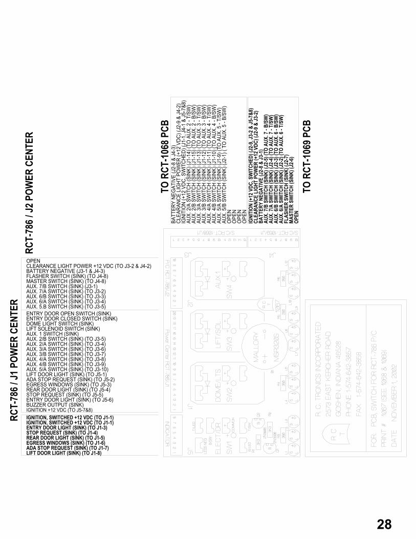
RCT-786 Power Center J1 and J2, Interface between Power Center PCB and Dash Switch PCB. J1-1 Ignition +12 VDC (To J4-8) J1-2 Buzzer Output (Sink) J1-3 Entry Door Light (Sink) (To J4-6) J1-4 Stop Request (Sink) (To J4-5) J1-5 Rear Door Light (Sink) (To J4-4) J1-6 Egress Windows (Sink) (To J4-3 J1-7 ADA Stop Request (Sink) (To J4-2) J1-8 Lift Door Light (Sink) (To J4-1) J1-9 Aux. 5/A Switch (Sink) (To J3-) J1-10 Aux 4/B Switch (Sink) (To Aux. 4-T/SW) J1-11 Aux. 4/A Switch (Sink) (To Aux. 4-B/SW) J1-12 Aux 3/B Switch (Sink) (To Aux. 3-T/SW) J1-13 Aux. 3/A Switch (Sink) (To Aux. 3-B/SW) J1-14 Aux. 2/A Switch (Sink) (To Aux.2-T/SW) J1-15 Aux. 2/B Switch (Sink) (To Aux.2-B/SW) J1-16 Aux. 1 Switch (Sink) J1-17 Lift Solenoid Switch (Sink) J1-18 Dome Light Switch (Sink) J1-19 Entry Door Close Switch (Sink) J1-20 Entry Door Open Switch (Sink) J2-1 Aux. 5/B Switch (Sink) (To J3-5) J2-2 Aux. 6/A Switch (Sink) (To J3-4) J2-3 Aux 6/B Switch (Sink) (To J3-3) J2-4 Aux 7/A Switch (Sink) (To J3-2) J2-5 Aux. 7/B Switch (Sink) (To J3-1) J2-6 Master Switch (Sink) J2-7 Flasher Switch (Sink) J2-8 Battery Negative J2-9 Clearance Light Power +12 VDC J2-10 Ignition (+12 VDC, Switched)(to J4-7) Interface between RCT-786 Power Center and ADA PCB, RCT-1010 J3-1 Shift Lock Indicator. (Sink 1-Ampere Maximum) J3-2 Transmission In Park. (Sink 1-Ampere Maximum) J3-3 Lift Enabled Indicator. (Sink 1-Ampere Maximum) J3-4 Park Brake Set Indicator. (Sink 1-Ampere Maximum) J3-5 Lift Door Open Indicator. (Sink 1-Ampere Maximum) J3-6 Lift Switch On. (Sink 1 Ampere Maximum) J3-7 Ignition (+12 VDC, Switched) J3-8 Ignition (+12 VDC, Switched)
12

13

14

Placing this switch to the "ON"position, will cause relay 18with it's output at terminal #28not to alternate it's output.
With a ground input to ADA, terminal #39 will cause alter-nating buzzer so long as the input is present. This switchsetting is; #1 "OFF", #3 "ON".
With a ground input to "StopRequest", terminal #40 willoperate buzzer so long as the input is present. This switch setting is; #4 "OFF" & #2 "ON".
Switch #2 (SC) "OFF" will keep power on "Close", terminal #3 with a ground at "Door Is Closed", terminal #1.
SW1 - Selects positive or neg-ative output to terminal #12.
SW2 - Selects N.O. or N.C. contactto terminals #10 and #11.
SW3 - Selects N.O. or N.C. contactto terminals #47 and #48.
Placing switch #1 thru #4 willcause relays 6/A thru 7/B tooperate relay #22, terminal#37 & #38. Often used for,"Hot Water Solenoid".
Switch settings from R. C. Tronics, Inc. Solid tab depicts white switch tab.
Placing switch #1 "OFF" willpermit "Door Open" when thevehicle transmission is in drive.R. C. TRONICS, INC. RECOMM-ENDS LEAVING THIS SWITCHIN THE "ON" POSITION.
D/SW. A D/SW. B
6/A = Relay #22, Term. #376/B = Relay #22, Term. #377/A = Relay #22, Term. #377/B = Relay #22, Term. #37
LC LOSC SO
Shift Lock withDash Lift Switch
Shift Lock with Park -Brake Term. #22
D/SW. C D/SW. D
Entry DoorInhibit "OFF"
Rear DoorInterlock "ON"
Dome LightInhibit "ON"
D/SW. E D/SW. F
"ON" causes relay #18not to alternate ON & OFF.
Placing switch #1 to the "OFF" position will not permit the "Shift Lock", relay #26 from energizingwith "Lift Switch", "ON". The out-puts are at terminals #10 & #11.
Placing switch #2 to the "OFF"position will not permit the "ShiftLock", relay #26 from energizingwith "Park Brake", terminal #20input. The outputs are at termin-als #10 & #11.
Switch #4 (SO) "OFF" will keep power on "Open", terminal #4 with ground at "Door Is Open", terminal #2.
Placing switch #2 in the "ON"position will not permit thesystem from shutting "OFF"either with the "Master Switch"or with "+12VDC OEM Ignition",terminal #31 with a ground in-put at "Rear Door Switch", ter-minal #18.
Placing switch #3 to the "ON"position will not permit the,"Dome Light", relay #3 fromenergizing when the "EntryDoor Is Open".
With switch #1 (LC), "OFF" & switch #2 (SC), "ON", a limit switch to ground must be used at terminal #1.
With switch #3 (LO), "OFF" & switch #4 (SO), "ON", a limit switch to ground must be used at terminal #2.
To substitute, "Entry Door Is Closed, terminal #1, place switch #1 (LC), "ON" & switch #2, "OFF".
To substitute, "Entry Door Is Open", terminal #2, place switch #3 (LO), "ON" & switch #4 (SO), "OFF".
LO = Limit OpenSC = Stop Close SO = Stop OpenLC = Limit Close
ADA MOMENTARY = #3 ON / #1 OFF.ADA MAINTAINED = #3 OFF / #1 ON.STOP MOMENTARY = #2 ON / #4 OFF.STOP MAINTAINED = #2 OFF / #4 ON.
With a momentary ground in-put to ADA, terminal #39 willcause a alternating buzzer tooperate until a ground is inputto terminal #22, "LIFT DOOR OPEN"This switch setting is; #3 "OFF" && #1 "ON".
With a momentary ground in-put to 'STOP REQUEST', term-inal #40, this will cause buzzerto operate until a ground is app-lied to, "ENTRY DOOR IS OPEN",at terminal #2. This switch set-ing is, #2 "OFF" & #4 "ON".
15

R. C. Tronics, Incorporated 2573 East Kercher Road Goshen, Indiana 46528 Phone 1-574-642-3857 www.rctronics.com Fax 1-574-642-3858 1-866-457-7790 Email; [email protected]
RCT-789 & RCT-790 Switch Panel Use with Power Center RCT-786
RCT-789, PCB J1 & J2 30 Conductor Data Cable, Interface to Power Center J1-1 Ignition, Switched +12 VDC J1-2 Buzzer Output (Sink) J1-3 Entry Door Light (Sink) (to J4-6) J1-4 Stop Request (Sink) (to J4-5) J1-5 Rear Door Light (Sink) (to J4-4) J1-6 Egress Windows (Sink) (to J4-3) J1-7 ADA Stop Request (Sink) (to J4-2) J1-8 Lift Door Light (Sink) (to J4-1) J1-9 Aux. 5/A Switch (Sink) (to Aux. 5 – T/SW) J1-10 Aux 4/B Switch (Sink) (to Aux. 4 – B/SW) J1-11 Aux. 4/A Switch (Sink) (to Aux. 4 – T/SW) J1-12 Aux 3/B Switch (Sink) (to Aux. 3 – B/SW) J1-13 Aux. 3/A Switch (Sink) (to Aux. 3 – T/SW) J1-14 Aux. 2/A Switch (Sink) (to Aux. 2 – T/SW) J1-15 Aux. 2/B Switch (Sink) (to Aux. 2 – B/SW) J1-16 Aux. 1 Switch (Sink) J1-17 Lift Solenoid Switch (Sink) J1-18 Dome Light Switch (Sink) J1-19 Entry Door Close Switch (Sink) J1-20 Entry Door Open Switch (Sink) J2-1 Aux. 5/B Switch (Sink) (to Aux. 5 – B/SW) J2-2 Aux. 6/A Switch (Sink) (to Aux. 6 – T/SW) J2-3 Aux 6/B Switch (Sink) (to Aux. 6 – B/SW) J2-4 Aux 7/A Switch (Sink) (to Aux. 7 – T/SW) J2-5 Aux. 7/B Switch (Sink) (to Aux. 7 – B/SW) J2-6 Master Switch (Sink) J2-7 Flasher Switch (Sink) J2-8 Battery Negative J2-9 Clearance Light Power +12 VDC J2-10 Spare (to J4-7)
16

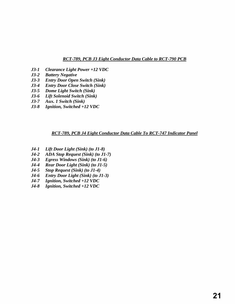
RCT-789, PCB J3 Eight Conductor Data Cable to RCT-790 PCB J3-1 Clearance Light Power +12 VDC J3-2 Battery Negative J3-3 Entry Door Open Switch (Sink) J3-4 Entry Door Close Switch (Sink) J3-5 Dome Light Switch (Sink) J3-6 Lift Solenoid Switch (Sink) J3-7 Aux. 1 Switch (Sink) J3-8 Ignition, Switched +12 VDC
RCT-789, PCB J4 Eight Conductor Data Cable To RCT-747 Indicator Panel
J4-1 Lift Door Light (Sink) (to J1-8) J4-2 ADA Stop Request (Sink) (to J1-7) J4-3 Egress Windows (Sink) (to J1-6) J4-4 Rear Door Light (Sink) (to J1-5) J4-5 Stop Request (Sink) (to J1-4) J4-6 Entry Door Light (Sink) (to J1-3) J4-7 Ignition, Switched +12 VDC J4-8 Ignition, Switched +12 VDC
17

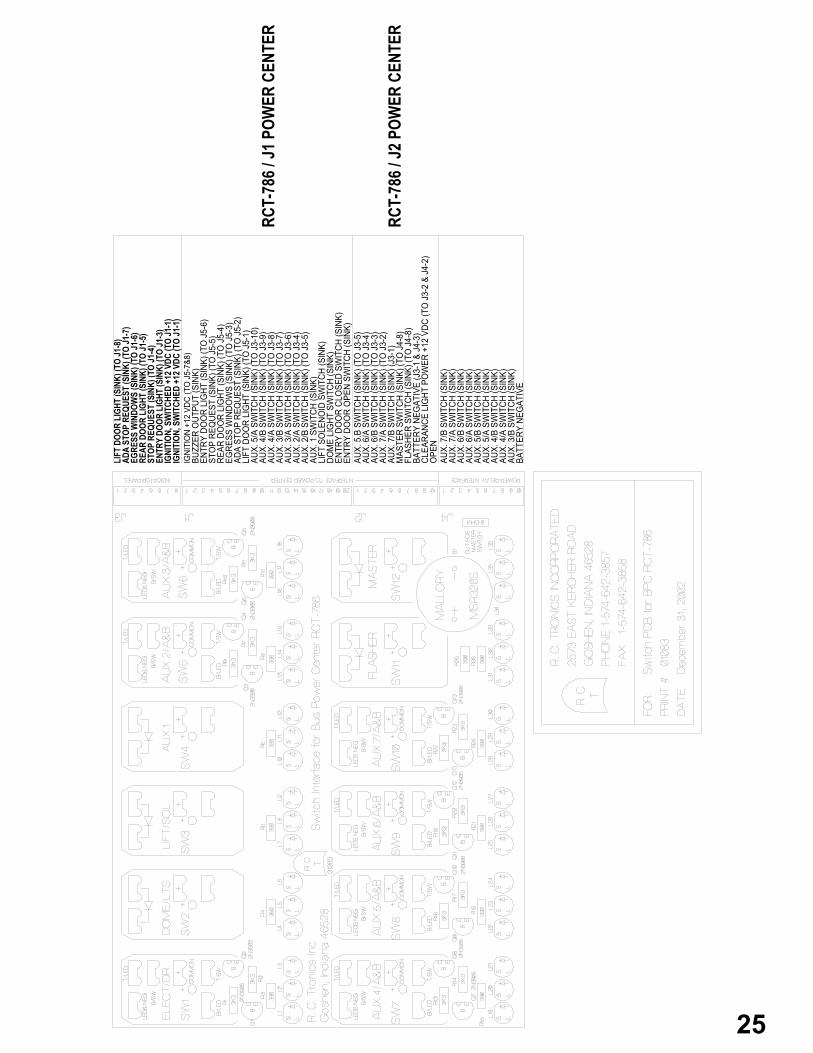
Ignition, Switched, +12VDCIgnition, Switched, +12VDCEntry Door Light (Sink @ 1 ampere)(From J1-3Stop Request (Sink @ 1 Ampere)(From J1-4)Rear Door Light (Sink @ 1 Ampere)(From J1-5)Egress Windows (Sink @ 1 Ampere)(From J1-6)ADA Stop Request (Sink @ 1 Ampere)(From J1-7)Lift Door Light (Sink @ 1 Ampere)(From J1-8)
Spare (To J1-7)Clearance Light Power +12VDCBattery NegativeFlasher Switch (Sink)Master Switch (Sink)Aux. 7/B Switch (Sink)(To J3-1)Aux. 7/A Switch (Sink)(To J3-2)Aux. 6/B Switch (Sink)(To J3-3)Aux. 6/A Switch (Sink)(To J3-4)Aux. 5/B Switch (Sink)(to J3-5)
Entry Door Open Switch (Sink)Entry Door Close Switch (Sink)Dome Light Switch (Sink)Lift Solenoid Switch (Sink)Aux. 1 Switch (Sink)
Lift Door Light (Sink)(To J4-1)ADA Stop Request (Sink)(To J4-2)Egress Windows (Sink)(To J4-3)Rear Door Light (Sink)(To J4-4)Stop Request (Sink)(To J4-5)Entry Door Light (Sink)(To J4-6)Buzzer Output (Sink)Ignition +12 VDC (To J4-8)
Ignition +12 VDC (To J4-8)Aux. 1 Switch (Sink)Lift Solenoid Switch (Sink)Dome Light Switch (Sink)Entry Door Close Switch (Sink)Entry Door Open Switch (Sink)Battery NegativeClearance Light Power +12VDC
To RCT-786 / J2
RCT-786 / J1
To RCT-790 / J1
To RCT-747 PCB, Indicator
Aux. 5 Switch (Sink) (to Aux 5 - T/SW)Aux. 4/B Switch (Sink) (to Aux. 4 - B/SW)Aux. 4/A Switch (Sink) (to Aux. 4 - T/SW)Aux. 3/B Switch (Sink) (to Aux. 3 - B/SW)Aux. 3/A Switch (Sink) (to Aux. 3 - T/SW)
Aux. 2/B Switch (Sink) (to Aux. 2 - B/SW)Aux. 2/A Switch (Sink) (to Aux. 2 - T/SW)
(to Aux. 7 - B/SW)(to Aux. 7 - T/SW)(to Aux. 6 - B/SW)(to Aux. 6 - T/SW)(to Aux. 5 - B/SW)
18

Ignition +12 VDC (To J4-8)Aux. 1 Switch (Sink)Lift Solenoid Switch (Sink)Dome Light Switch (Sink)Entry Door Close Switch (Sink)Entry Door Open Switch (Sink)Battery NegativeClearance Light Power +12VDC
To RCT-789 / J3
19

R. C. Tronics, Incorporated 2573 East Kercher Road Goshen, Indiana 46528 Phone 1-574-642-3857 www.rctronics.com Fax 1-574-642-3858 1-866-457-7790 Email; [email protected]
RCT-948 Switch Panel.
Used with Power Center RCT-786 J1 and J2, Interface Between Power Center PCB and Dash Switch PCB. J1-1 Ignition +12 VDC (To J4-8) J1-2 Buzzer Output (Sink) J1-3 Entry Door Light (Sink) (To J4-6) J1-4 Stop Request (Sink) (To J4-5) J1-5 Rear Door Light (Sink) (To J4-4) J1-6 Egress Windows (Sink) (To J4-3 J1-7 ADA Stop Request (Sink) (To J4-2) J1-8 Lift Door Light (Sink) (To J4-1) J1-9 Aux. 5/A Switch (Sink) (To J3-) J1-10 Aux 4/B Switch (Sink) (To Aux. 4-T/SW) J1-11 Aux. 4/A Switch (Sink) (To Aux. 4-B/SW) J1-12 Aux 3/B Switch (Sink) (To Aux. 3-T/SW) J1-13 Aux. 3/A Switch (Sink) (To Aux. 3-B/SW) J1-14 Aux. 2/A Switch (Sink) (To Aux.2-T/SW) J1-15 Aux. 2/B Switch (Sink) (To Aux.2-B/SW) J1-16 Aux. 1 Switch (Sink) J1-17 Lift Solenoid Switch (Sink) J1-18 Dome Light Switch (Sink) J1-19 Entry Door Close Switch (Sink) J1-20 Entry Door Open Switch (Sink) J2-1 Aux. 5/B Switch (Sink) (To J3-5) J2-2 Aux. 6/A Switch (Sink) (To J3-4) J2-3 Aux 6/B Switch (Sink) (To J3-3) J2-4 Aux 7/A Switch (Sink) (To J3-2) J2-5 Aux. 7/B Switch (Sink) (To J3-1) J2-6 Master Switch (Sink) J2-7 Flasher Switch (Sink) J2-8 Battery Negative J2-9 Clearance Light Power +12 VDC J2-10 (Ignition (+12 VDC, Switched)( to J4-7)
20
RCT-789, PCB J3 Eight Conductor Data Cable to RCT-790 PCB J3-1 Clearance Light Power +12 VDC J3-2 Battery Negative J3-3 Entry Door Open Switch (Sink) J3-4 Entry Door Close Switch (Sink) J3-5 Dome Light Switch (Sink) J3-6 Lift Solenoid Switch (Sink) J3-7 Aux. 1 Switch (Sink) J3-8 Ignition, Switched +12 VDC
RCT-789, PCB J4 Eight Conductor Data Cable To RCT-747 Indicator Panel
J4-1 Lift Door Light (Sink) (to J1-8) J4-2 ADA Stop Request (Sink) (to J1-7) J4-3 Egress Windows (Sink) (to J1-6) J4-4 Rear Door Light (Sink) (to J1-5) J4-5 Stop Request (Sink) (to J1-4) J4-6 Entry Door Light (Sink) (to J1-3) J4-7 Ignition, Switched +12 VDC J4-8 Ignition, Switched +12 VDC
21

Ignition, Switched, +12VDCIgnition, Switched, +12VDC
Aux. 5/A Switch (Sink) (From J1-9)Aux. 5/B Switch (Sink) (From J2-1)Aux. 6/A Switch (Sink) (From J2-2)Aux. 6/B Switch (Sink) (From J2-3)Aux. 7/A Switch (Sink) (From J2-4)Aux. 7/B Switch (Sink) (From J2-5
Battery NegativeSpare
Entry Door Light (Sink @ 1 ampere)(From J1-3Stop Request (Sink @ 1 Ampere)(From J1-4)Rear Door Light (Sink @ 1 Ampere)(From J1-5)Egress Windows (Sink @ 1 Ampere)(From J1-6)ADA Stop Request (Sink @ 1 Ampere)(From J1-7)Lift Door Light (Sink @ 1 Ampere)(From J1-8)
Spare (To J1-7)Clearance Light Power +12VDCBattery NegativeFlasher Switch (Sink)Master Switch (Sink)Aux. 7/B Switch (Sink)(To J3-1)Aux. 7/A Switch (Sink)(To J3-2)Aux. 6/B Switch (Sink)(To J3-3)Aux. 6/A Switch (Sink)(To J3-4)Aux. 5/B Switch (Sink)(to J3-5)Entry Door Open Switch (Sink)Entry Door Close Switch (Sink)Dome Light Switch (Sink)Lift Solenoid Switch (Sink)Aux. 1 Switch (Sink)Aux. 2/B Switch (Sink)(To Aux.2-B/Switch)Aux 2/A Switch (Sink)(To Aux.2-T/Switch)Aux. 3/A Switch (Sink)(To Aux.3-B/Switch)Aux. 3/B Switch (Sink)(To Aux. 3-T/Switch)Aux. 4/A Switch (Sink)(To 4-B/Switch)Aux. 4/B Switch (Sink)(To Aux. 4-T/Switch)Aux. 5/A Switch (Sink)(To J3-6)Lift Door Light (Sink)(To J4-1)ADA Stop Request (Sink)(To J4-2)Egress Windows (Sink)(To J4-3)Rear Door Light (Sink)(To J4-4)Stop Request (Sink)(To J4-5)Entry Door Light (Sink)(To J4-6)Buzzer Output (Sink)Ignition +12 VDC (To J4-8)
To RCT-786 / J2
To RCT-786 / J1
Spare RelayInterface
To RCT-747PCB
Indicator
22

R. C. Tronics, Incorporated 2573 East Kercher Road Goshen, Indiana 46528 Phone 1-574-642-3857 www.rctronics.com Fax 1-574-642-3858 1-866-457-7790 Email; [email protected]
RCT-1083 Switch Panel.
Used with Power Center RCT-786 J1 and J2, Interface Between Power Center PCB and Dash Switch PCB. J1-1 Ignition +12 VDC (To J4-8) J1-2 Buzzer Output (Sink) J1-3 Entry Door Light (Sink) (To J4-6) J1-4 Stop Request (Sink) (To J4-5) J1-5 Rear Door Light (Sink) (To J4-4) J1-6 Egress Windows (Sink) (To J4-3 J1-7 ADA Stop Request (Sink) (To J4-2) J1-8 Lift Door Light (Sink) (To J4-1) J1-9 Aux. 5/A Switch (Sink) (To J3-) J1-10 Aux 4/B Switch (Sink) (To Aux. 4-T/SW) J1-11 Aux. 4/A Switch (Sink) (To Aux. 4-B/SW) J1-12 Aux 3/B Switch (Sink) (To Aux. 3-T/SW) J1-13 Aux. 3/A Switch (Sink) (To Aux. 3-B/SW) J1-14 Aux. 2/A Switch (Sink) (To Aux.2-T/SW) J1-15 Aux. 2/B Switch (Sink) (To Aux.2-B/SW) J1-16 Aux. 1 Switch (Sink) J1-17 Lift Solenoid Switch (Sink) J1-18 Dome Light Switch (Sink) J1-19 Entry Door Close Switch (Sink) J1-20 Entry Door Open Switch (Sink) J2-1 Aux. 5/B Switch (Sink) (To J3-5) J2-2 Aux. 6/A Switch (Sink) (To J3-4) J2-3 Aux 6/B Switch (Sink) (To J3-3) J2-4 Aux 7/A Switch (Sink) (To J3-2) J2-5 Aux. 7/B Switch (Sink) (To J3-1) J2-6 Master Switch (Sink) J2-7 Flasher Switch (Sink) J2-8 Battery Negative J2-9 Clearance Light Power +12 VDC J2-10 OPEN
23

J4 Connector, Spare Relays on Power Center PCB. J4-1 Aux 7/B Switch (Sink) (From J2-5) J4-2 Aux 7/A Switch (Sink) (From J2-4) J4-3 Aux 6/B Switch (Sink) (From J2-3) J4-4 Aux 6/A Switch (Sink) (From J2-2) J4-5 Aux 5/B Switch (Sink) (From J2-1) J4-6 Aux 5/A Switch (Sink) (From J1-9) J4-7 Aux 4/B Switch (Sink (From J1-10) J4-8 Aux 4/A Switch (Sink) (From J1-11) J4-9 Aux 3/B Switch (Sink) (From J1-12) J4-10 Battery Negative J3 Connector, Indicating Lights J3-1 Lift Door Light, sink @ 1 ampere. (From J1-8) J3-2 ADA Stop Request, sink @ 1 ampere. (From J1-7) J3-3 Egress Windows, sink @ 1 ampere. (From J1-6) J3-4 Rear Door Light, sink @ 1 ampere. (From J1-5) J3-5 Stop Request, sink @ 1 ampere. (From J1-4) J3-6 Entry Door Light, sink @ 1 ampere. (From J1-3) J3-7 Ignition (+12 VDC, Switched) (From J1-1) J3-8 Ignition (+12 VDC, Switched) (From J1-1)
24
RCT-
786 /
J2 P
OWER
CEN
TER
RCT-
786 /
J1 P
OWER
CEN
TER
IGNI
TIO
N +1
2 VD
C (T
O J
5-7&
8)BU
ZZER
OUT
PUT
(SIN
K)EN
TRY
DOO
R LI
GHT
(SIN
K) (T
O J
5-6)
STO
P RE
QUE
ST (S
INK)
(TO
J5-
5)RE
AR D
OO
R LI
GHT
(SIN
K) (T
O J
5-4)
EGRE
SS W
INDO
WS
(SIN
K) (T
O J
5-3)
ADA
STO
P RE
QUE
ST (S
INK)
(TO
J5-
2)LI
FT D
OO
R LI
GHT
(SIN
K) (T
O J
5-1)
AUX.
5/A
SW
ITCH
(SIN
K) (T
O J
3-10
)AU
X. 4
/B S
WIT
CH (S
INK)
(TO
J3-
9)AU
X. 4
/A S
WIT
CH (S
INK)
(TO
J3-
8)AU
X. 3
/B S
WIT
CH (S
INK)
(TO
J3-
7)AU
X. 3
/A S
WIT
CH (S
INK)
(TO
J3-
6)AU
X. 2
/A S
WIT
CH (S
INK)
(TO
J3-
4)AU
X. 2
/B S
WIT
CH (S
INK)
(TO
J3-
5)AU
X. 1
SW
ITCH
(SIN
K)LI
FT S
OLE
NOID
SW
ITCH
(SIN
K)DO
ME
LIG
HT S
WIT
CH (S
INK)
ENTR
Y DO
OR
CLO
SED
SWIT
CH (S
INK)
ENTR
Y DO
OR
OPE
N SW
ITCH
(SIN
K)AU
X. 5
.B S
WIT
CH (S
INK)
(TO
J3-
5)AU
X. 6
/A S
WIT
CH (S
INK)
(TO
J3-
4)AU
X. 6
/B S
WIT
CH (S
INK)
(TO
J3-
3)AU
X. 7
/A S
WIT
CH (S
INK)
(TO
J3-
2)AU
X. 7
/B S
WIT
CH (S
INK)
(J3-
1)M
ASTE
R SW
ITCH
(SIN
K) (T
O J
4-8)
FLAS
HER
SWIT
CH (S
INK)
(TO
J4-
8)BA
TTER
Y NE
GAT
IVE
(J3-
1 &
J4-3
)CL
EARA
NCE
LIG
HT P
OW
ER +
12 V
DC (T
O J
3-2
& J4
-2)
OPE
N
LIFT
DOO
R LI
GHT
(SIN
K) (T
O J1
-8)
ADA
STOP
REQ
UEST
(SIN
K) (T
O J1
-7)
EGRE
SS W
INDO
WS
(SIN
K) (T
O J1
-6)
REAR
DOO
R LI
GHT
(SIN
K) (T
O J1
-5)
STOP
REQ
UEST
(SIN
K) (T
O J1
-4)
ENTR
Y DO
OR L
IGHT
(SIN
K) (T
O J1
-3)
IGNI
TION
, SW
ITCH
ED +
12 V
DC (T
O J1
-1)
IGNI
TION
, SW
ITCH
ED +
12 V
DC (T
O J1
-1)
AUX.
7/A
SW
ITCH
(SIN
K)AU
X. 6
/B S
WIT
CH (S
INK)
AUX.
6/A
SW
ITCH
(SIN
K)
AUX.
7/B
SW
ITCH
(SIN
K)
AUX.
5/B
SW
ITCH
(SIN
K)AU
X. 5
/A S
WIT
CH (S
INK)
AUX.
4/B
SW
ITCH
(SIN
K)AU
X. 4
/A S
WIT
CH (S
INK)
AUX.
3/B
SW
ITCH
(SIN
K)BA
TTER
Y NE
GAT
IVE
25

R. C. Tronics, Incorporated 2573 East Kercher Road Goshen, Indiana 46528 Phone 1-574-642-3857 www.rctronics.com Fax 1-574-642-3858 1-866-457-7790 Email; [email protected]
RCT-1067, RCT-1068 & RCT-1069 Use with Power Center RCT-786
RCT-1067 PCB, J1 & J2, 30 Conductor Data Cable, Interface to Power Center J1-1 Ignition +12 VDC (To J5-7&8) J1-2 Buzzer Output (Sink) J1-3 Entry Door Light (Sink) (To J5-6) J1-4 Stop Request (Sink) (To J5-5) J1-5 Rear Door Light (Sink) (To J5-4) J1-6 Egress Windows (Sink) (To J5-3 J1-7 ADA Stop Request (Sink) (To J5-2) J1-8 Lift Door Light (Sink) (To J5-1) J1-9 Aux. 5/A Switch (Sink) (To J3-10) J1-10 Aux 4/B Switch (Sink) (To J3-9) J1-11 Aux. 4/A Switch (Sink) (To J3-8) J1-12 Aux 3/B Switch (Sink) (To J3-7) J1-13 Aux. 3/A Switch (Sink) (To J3-6) J1-14 Aux. 2/A Switch (Sink) (To J3-4) J1-15 Aux. 2/B Switch (Sink) (To J3-5) J1-16 Aux. 1 Switch (Sink) J1-17 Lift Solenoid Switch (Sink) J1-18 Dome Light Switch (Sink) J1-19 Entry Door Close Switch (Sink) J1-20 Entry Door Open Switch (Sink) J2-1 Aux. 5/B Switch (Sink) (To J3-5) J2-2 Aux. 6/A Switch (Sink) (To J3-4) J2-3 Aux 6/B Switch (Sink) (To J3-3) J2-4 Aux 7/A Switch (Sink) (To J3-2) J2-5 Aux. 7/B Switch (Sink) (To J3-1) J2-6 Master Switch (Sink) (To J4-8) J2-7 Flasher Switch (Sink) (To J4-8) J2-8 Battery Negative (J3-1 & J4-3) J2-9 Clearance Light Power +12 VDC (To J3-2 & J4-2) J2-10 Open
26

RCT-1067 PCB TO RCT-1068 PCB.
J3-1 Battery Negative (J2-8 & J4-3) J3-2 Clearance Light Power (+12 VDC) (To J2-9 & J4-2) J3-3 Ignition (+12 VDC, Switched) (J1-1, J4-1 & J5-7 & 8) J3-4 Aux. 2/A Switch (Sink) (J1-14) (To Aux. 2 – T/SW) J3-5 Aux. 2/B Switch (Sink) (J1-15) (To Aux. 2 – B/SW) J3-6 Aux. 3/A Switch (Sink) (J1-13) (To Aux. 3 – T/SW) J3-7 Aux. 3/B Switch (Sink) (J1-12) (To Aux. 3 – B/SW) J3-8 Aux. 4/A Switch (Sink) (J!-11) (To Aux. 4 – T/SW) J3-9 Aux. 4/B Switch (Sink) (J1-10) (To Aux. 4 – B/SW) J3-10 Aux. 5/A Switch (Sink) (J1-9) (To Aux. 5 – T/SW) J3-11 Aux. 5/B Switch (Sink) (J2-1) (To Aux. 5 – B/SW) J3-12 Open J3-13 Open J3-14 Open J3-15 Open
RCT-1067 PCB to RCT-1069 PCB
J4-1 Ignition (+12 VDC, Switched) (J2-9, J3-2 & J5-7&8) J4-2 Clearance Light Power (+12 VDC) (J2-9 & J3-2) J4-3 Battery Negative (J2-8 & J3-1) J4-4 Aux. 7/B Switch (Sink) (J2-5) (To Aux. 7 – B/SW) J4-5 Aux. 7/A Switch (Sink) (J2-4) (To Aux. 7 – T/SW) J4-6 Aux. 6/B Switch (Sink) (J2-3) (To Aux. 6 – B/SW) J4-7 Aux. 6/A Switch (Sink) (J2-2) (To Aux. 6 – T/SW) J4-8 Flasher Switch (Sink) (J2-7) J4-9 Master Switch (Sink) (J2-6) J4-10 Open
RCT-789, PCB J4 Eight Conductor Data Cable To RCT-747 Indicator Panel
J5-1 Lift Door Light (Sink) (To J1-8) J5-2 ADA Stop Request (Sink) (To J1-7) J5-3 Egress Windows (Sink) (To J1-6) J5-4 Rear Door Light (Sink) (To J1-5) J5-5 Stop Request (Sink) (To J1-4) J5-6 Entry Door Light (Sink) (To J1-3) J5-7 Ignition, Switched +12 VDC (To J1-1) J5-8 Ignition, Switched +12 VDC (To J1-1)
27
IGNITION +12 VDC (TO J5-7&8)BUZZER OUTPUT (SINK)ENTRY DOOR LIGHT (SINK) (TO J5-6)STOP REQUEST (SINK) (TO J5-5)REAR DOOR LIGHT (SINK) (TO J5-4)EGRESS WINDOWS (SINK) (TO J5-3)ADA STOP REQUEST (SINK) (TO J5-2)LIFT DOOR LIGHT (SINK) (TO J5-1)AUX. 5/A SWITCH (SINK) (TO J3-10)AUX. 4/B SWITCH (SINK) (TO J3-9)AUX. 4/A SWITCH (SINK) (TO J3-8)AUX. 3/B SWITCH (SINK) (TO J3-7)AUX. 3/A SWITCH (SINK) (TO J3-6)AUX. 2/A SWITCH (SINK) (TO J3-4)AUX. 2/B SWITCH (SINK) (TO J3-5)AUX. 1 SWITCH (SINK)LIFT SOLENOID SWITCH (SINK)DOME LIGHT SWITCH (SINK)ENTRY DOOR CLOSED SWITCH (SINK)ENTRY DOOR OPEN SWITCH (SINK)AUX. 5.B SWITCH (SINK) (TO J3-5)AUX. 6/A SWITCH (SINK) (TO J3-4)AUX. 6/B SWITCH (SINK) (TO J3-3)AUX. 7/A SWITCH (SINK) (TO J3-2)AUX. 7/B SWITCH (SINK) (J3-1)MASTER SWITCH (SINK) (TO J4-8)FLASHER SWITCH (SINK) (TO J4-8)BATTERY NEGATIVE (J3-1 & J4-3)CLEARANCE LIGHT POWER +12 VDC (TO J3-2 & J4-2)OPEN
RCT-
786 /
J2 P
OWER
CEN
TER
RCT-
786 /
J1 P
OWER
CEN
TER
OPEN
MAS
TER
SWIT
CH (S
INK)
(J2-
6)FL
ASHE
R SW
ITCH
(SIN
K) (J
2-7)
AUX.
6/A
SW
ITCH
(SIN
K) (J
2-2)
(TO
AUX.
6 -
T/SW
)AU
X. 6
/B S
WIT
CH (S
INK)
(J2-
3) (T
O AU
X. 6
- B/
SW)
AUX.
7/A
SW
ITCH
(SIN
K) (J
2-4)
(TO
AUX.
7 -
T/SW
)AU
X. 7
/B S
WIT
CH (S
INK)
(J2-
5) (T
O AU
X. 7
- B/
SW)
BATT
ERY
NEGA
TIVE
(J2-
8 &
J3-1
)CL
EARA
NCE
LIGH
T PO
WER
(+12
VDC
) (J2
-9 &
J3-
2)IG
NITI
ON (+
12 V
DC, S
WIT
CHED
) (J2
-9, J
3-2
& J5
-7&8
)O
PEN
OPE
NO
PEN
OPE
NAU
X. 5
/B S
WIT
CH (S
INK)
(J2-
1) (
TO A
UX. 5
- B/
SW)
AUX.
5/A
SW
ITCH
(SIN
K) (J
1-9)
(TO
AUX
. 5 -
T/SW
)AU
X. 4
/B S
WIT
CH (S
INK)
(J1-
10) (
TO A
UX. 4
- B/
SW)
AUX.
4/A
SW
ITCH
(SIN
K) (J
1-11
) (TO
AUX
. 4 -
T/SW
)AU
X. 3
/B S
WIT
CH (S
INK)
(J1-
12) (
TO A
UX. 3
- B/
SW)
AUX.
3/A
SW
ITCH
(SIN
K) (J
1-13
) (TO
AUX
. 3 -
T/SW
)AU
X. 2
/B S
WIT
CH (S
INK)
(J1-
15) (
TO A
UX. 2
- B/
SW)
AUX.
2/A
SW
ITCH
(SIN
K) (J
1-14
) (TO
AUX
. 2 -
T/SW
)IG
NITI
ON
(+12
VDC
, SW
ITCH
ED) (
J1-1
, J4-
1 &
J5-7
&8)
CLEA
RANC
E LI
GHT
PO
WER
(+12
VDC
) (J2
-9 &
J4-
2)BA
TTER
Y NE
GAT
IVE
(J2-
8 &
J4-3
)TO
RCT
-106
8 PCB
TO R
CT-1
069 P
CB
LIFT DOOR LIGHT (SINK) (TO J1-8)ADA STOP REQUEST (SINK) (TO J1-7)EGRESS WINDOWS (SINK) (TO J1-6)REAR DOOR LIGHT (SINK) (TO J1-5)STOP REQUEST (SINK) (TO J1-4)ENTRY DOOR LIGHT (SINK) (TO J1-3)IGNITION, SWITCHED +12 VDC (TO J1-1)IGNITION, SWITCHED +12 VDC (TO J1-1)
28

OPE
NO
PEN
OPE
NO
PEN
AUX.
5/B
SW
ITCH
(SIN
K) (J
2-1)
( TO
AUX
. 5 -
B/SW
)AU
X. 5
/A S
WIT
CH (S
INK)
(J1-
9) (T
O A
UX. 5
- T/
SW)
AUX.
4/B
SW
ITCH
(SIN
K) (J
1-10
) (TO
AUX
. 4 -
B/SW
)AU
X. 4
/A S
WIT
CH (S
INK)
(J1-
11) (
TO A
UX. 4
- T/
SW)
AUX.
3/B
SW
ITCH
(SIN
K) (J
1-12
) (TO
AUX
. 3 -
B/SW
)AU
X. 3
/A S
WIT
CH (S
INK)
(J1-
13) (
TO A
UX. 3
- T/
SW)
AUX.
2/B
SW
ITCH
(SIN
K) (J
1-15
) (TO
AUX
. 2 -
B/SW
)AU
X. 2
/A S
WIT
CH (S
INK)
(J1-
14) (
TO A
UX. 2
- T/
SW)
IGNI
TIO
N (+
12 V
DC, S
WIT
CHED
) (J1
-1, J
4-1
& J5
-7&8
)CL
EARA
NCE
LIG
HT P
OW
ER (+
12 V
DC) (
J2-9
& J
4-2)
BATT
ERY
NEG
ATIV
E (J
2-8
& J4
-3)
OPE
NO
PEN
OPE
NO
PEN
AUX.
5/B
SW
ITCH
(SIN
K) (J
2-1)
( TO
AUX
. 5 -
B/SW
)AU
X. 5
/A S
WIT
CH (S
INK)
(J1-
9) (T
O A
UX. 5
- T/
SW)
AUX.
4/B
SW
ITCH
(SIN
K) (J
1-10
) (TO
AUX
. 4 -
B/SW
)AU
X. 4
/A S
WIT
CH (S
INK)
(J1-
11) (
TO A
UX. 4
- T/
SW)
AUX.
3/B
SW
ITCH
(SIN
K) (J
1-12
) (TO
AUX
. 3 -
B/SW
)AU
X. 3
/A S
WIT
CH (S
INK)
(J1-
13) (
TO A
UX. 3
- T/
SW)
AUX.
2/B
SW
ITCH
(SIN
K) (J
1-15
) (TO
AUX
. 2 -
B/SW
)AU
X. 2
/A S
WIT
CH (S
INK)
(J1-
14) (
TO A
UX. 2
- T/
SW)
IGNI
TIO
N (+
12 V
DC, S
WIT
CHED
) (J1
-1, J
4-1
& J5
-7&8
)CL
EARA
NCE
LIG
HT P
OW
ER (+
12 V
DC) (
J2-9
& J
4-2)
BATT
ERY
NEG
ATIV
E (J
2-8
& J4
-3)
To R
CT-1
067 P
CB
To R
CT-1
067 P
CB
29

OPEN
MAST
ER S
WIT
CH (S
INK)
(J2-
6)FL
ASHE
R SW
ITCH
(SIN
K) (J
2-7)
AUX.
6/A
SWIT
CH (S
INK)
(J2-
2) (T
O AU
X. 6
- T/S
W)
AUX.
6/B
SWIT
CH (S
INK)
(J2-
3) (T
O AU
X. 6
- B/S
W)
AUX.
7/A
SWIT
CH (S
INK)
(J2-
4) (T
O AU
X. 7
- T/S
W)
AUX.
7/B
SWIT
CH (S
INK)
(J2-
5) (T
O AU
X. 7
- B/S
W)
BATT
ERY
NEGA
TIVE
(J2-
8 & J3
-1)
CLEA
RANC
E LI
GHT
POW
ER (+
12 V
DC) (
J2-9
& J3
-2)
IGNI
TION
(+12
VDC
, SW
ITCH
ED) (
J2-9
, J3-
2 & J5
-7&8
)
To R
CT-1
067 P
CB
To R
CT-1
067 P
CB
30
OPEN
MAST
ER S
WIT
CH (S
INK)
(J2-
6)FL
ASHE
R SW
ITCH
(SIN
K) (J
2-7)
AUX.
6/A
SW
ITCH
(SIN
K) (J
2-2)
(TO
AUX.
6 -
T/SW
)AU
X. 6
/B S
WIT
CH (S
INK)
(J2-
3) (T
O AU
X. 6
- B/
SW)
AUX.
7/A
SW
ITCH
(SIN
K) (J
2-4)
(TO
AUX.
7 -
T/SW
)AU
X. 7
/B S
WIT
CH (S
INK)
(J2-
5) (T
O AU
X. 7
- B/
SW)
BATT
ERY
NEGA
TIVE
(J2-
8 &
J3-1
)CL
EARA
NCE
LIGH
T PO
WER
(+12
VDC
) (J2
-9 &
J3-
2)IG
NITI
ON (+
12 V
DC, S
WIT
CHED
) (J2
-9, J
3-2
& J5
-7&8
)
To R
CT-1
067
PCB
To R
CT-1
067
PCB
MARK
ER S
WIT
CH IN
PUT
NORM
ALLY
OPE
NMA
RKER
SW
ITCH
INPU
T NO
RMAL
LY O
PEN
HI-ID
LE L
ED N
EGAT
IVE
INPU
T (1
2 VD
C)HI
ILDE
POS
ITIV
E IN
PUT
(12
VDC)
MARK
ER L
ED N
EGAT
IVE
INPU
T (1
2 VD
C)M
ARKE
R LE
D PO
SITI
VE IN
PUT
(12
VDC)
HI-ID
LE S
WIT
CH IN
PUT
NORM
ALLY
OPE
NHI
-IDLE
SW
ITCH
INPU
T NO
RMAL
LY O
PEN
MIR
ROR
LED
NEGA
TIVE
INPU
T (1
2 VD
C)M
IRRO
R LE
D PO
SITI
VE IN
PUT
(12
VDC)
MIRR
OR S
WIT
CH IN
PUT
NORM
ALLY
OPE
NMI
RROR
SW
ITCH
INPU
T NO
RMAL
LY O
PEN
NOT
USED
NOT
USED
NOT
USED
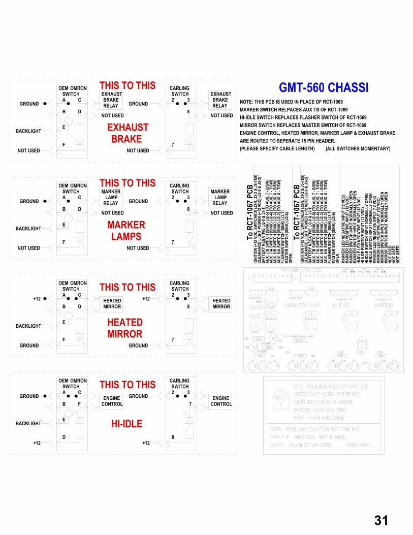
NOTE: THIS PCB IS USED IN PLACE OF RCT-1069
HI-IDLE SWITCH REPLACES FLASHER SWITCH OF RCT-1069MIRROR SWITCH REPLACES MASTER SWITCH OF RCT-1069
MARKER SWITCH RELPACES AUX 7/8 OF RCT-1069
(PLEASE SPECIFY CABLE LENGTH)
A
B
E
D
C
F
+12
BACKLIGHT
GROUND ENGINECONTROL
OEM OMRONSWITCH
+12
GROUND ENGINECONTROL
SWITCHCARLING
8
7
2 3
A
B
E
D
C
F
+12
BACKLIGHT
GROUND
OEM OMRONSWITCH
+12
GROUND
SWITCHCARLING
8
7
2 3HEATEDMIRROR
HEATEDMIRROR
A
B
E
D
C
F
BACKLIGHT
OEM OMRONSWITCH
GROUND
SWITCHCARLING
8
7
2 3MARKER
LAMP
NOT USED
GROUND
NOT USED
NOT USED
NOT USED
RELAY
MARKERLAMP
RELAY
A
B
E
D
C
F
BACKLIGHT
OEM OMRONSWITCH
GROUND
SWITCHCARLING
8
7
2 3
NOT USED
GROUND
NOT USED
NOT USED
NOT USED
RELAY RELAY
EXHAUSTBRAKE
EXHAUSTBRAKE
THIS TO THIS
HI-IDLE
THIS TO THIS
THIS TO THIS
THIS TO THIS
HEATEDMIRROR
MARKERLAMPS
EXHAUSTBRAKE ARE ROUTED TO SEPERATE 15 PIN HEADER.
ENGINE CONTROL, HEATED MIRROR, MARKER LAMP & EXHAUST BRAKE,
(ALL SWITCHES MOMENTARY)
GMT-560 CHASSI
31
32

33

34

R. C. Tronics, Incorporated 2573 East Kercher Road Goshen, Indiana 46528 Phone 1-574-642-3857 www.rctronics.com Fax 1-574-642-3858 1-866-457-7790 Email; [email protected]
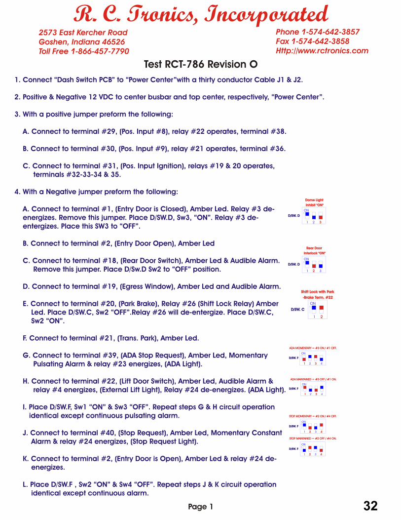
Test RCT-786 1. Connect Dash Switch Panel Via 20 pin and 10-pin Amp connector and then connect Battery Negative to top center of PCB and + VDC to Buss Bar. 2. Preset the following dip-switches. D/SWA Switch #1 “OFF” Switch #2 “ON” Switch #3 “OFF” Switch #4 “ON” D/SWB Switch #1 thru Switch #4 “OFF” D/SWC Switch #1 & #2 “ON” D/SWD Switch #1 “ON” Switch #2 “OFF” Switch #3 “OFF” D/SWE Switch #1 “OFF” D/SWF Switch #1 “OFF” Switch #2 “ON” Switch #3 “ON” Switch #4 “OFF” 3. With + VDC, perform the following. A. Connect to terminal #29 (+12 vdc Aux. #8), relay 22 should operate. B. Connect to terminal #30 (+12 vdc Aux. #9), relay 21 should operate. C. Connect to terminal #31 (+12 vdc OEM Ignition), Operate switch #8 (Master Switch), located Dash switch panel (PCB 789), relay’s 19 & 20 should operate. 4. With a jumper connected to batter negative, connect to the following terminals. A. #1 Entry Door Is Closed Amber Led Light. Dome Lights, Rly 3 deentergises. B. #2 Entry Door is Open Amber Led Light. C. #18 Rear Door Switch Amber Led Light and Audible Alarm. D. #19 Egress Windows Amber Led Light and Audible Alarm. E. #20 Park Brake Switch Amber Led Light. F. #21 Trans. Park Amber Led Light. G. #22 Lift Door Switch Amber Led Light, Audible Alarm & relay #4 operates. H. #39 ADA Stop Request Switch Led Light, Audible Alarm Alternating & relay 23 operates. I. #40 Stop Request Switch Led Light, Audible Alarm & relay 24 operates. J. #2 Entry Door Is Open relay 24 de-energizes. K. #22 Lift Door Switch relay 23 de-energizes.
35
R. C. Tronics, Incorporated 2573 East Kercher Road Goshen, Indiana 46528 Phone 1-574-642-3857 www.rctronics.com Fax 1-574-642-3858 1-866-457-7790 Email; [email protected]
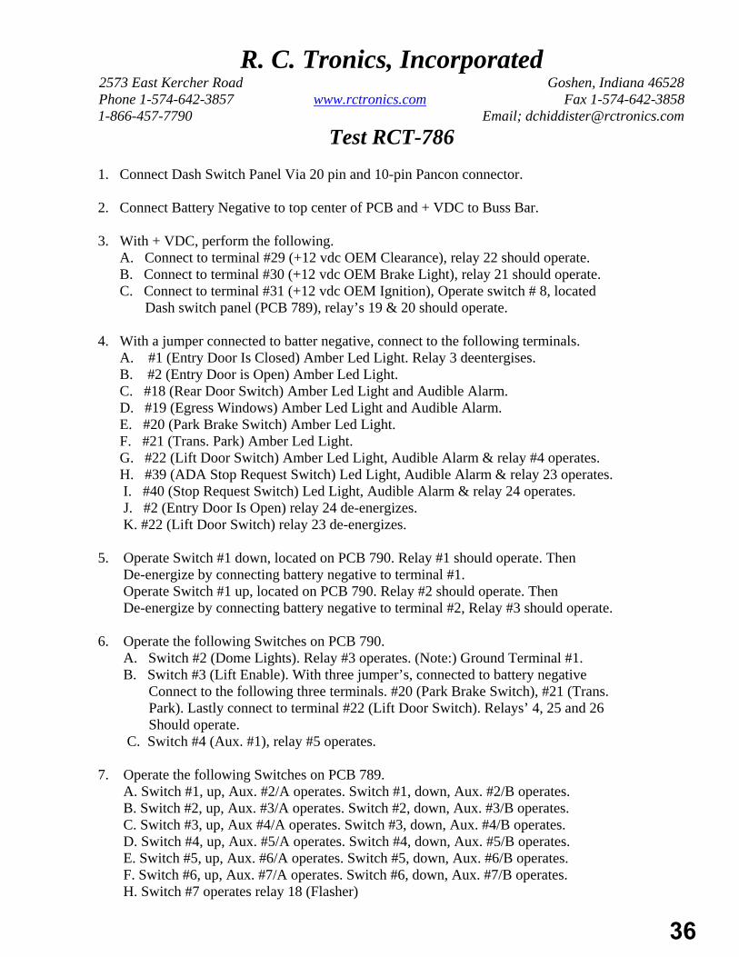
Test RCT-786 1. Connect Dash Switch Panel Via 20 pin and 10-pin Pancon connector. 2. Connect Battery Negative to top center of PCB and + VDC to Buss Bar. 3. With + VDC, perform the following. A. Connect to terminal #29 (+12 vdc OEM Clearance), relay 22 should operate. B. Connect to terminal #30 (+12 vdc OEM Brake Light), relay 21 should operate. C. Connect to terminal #31 (+12 vdc OEM Ignition), Operate switch # 8, located Dash switch panel (PCB 789), relay’s 19 & 20 should operate. 4. With a jumper connected to batter negative, connect to the following terminals. A. #1 (Entry Door Is Closed) Amber Led Light. Relay 3 deentergises. B. #2 (Entry Door is Open) Amber Led Light. C. #18 (Rear Door Switch) Amber Led Light and Audible Alarm. D. #19 (Egress Windows) Amber Led Light and Audible Alarm. E. #20 (Park Brake Switch) Amber Led Light. F. #21 (Trans. Park) Amber Led Light. G. #22 (Lift Door Switch) Amber Led Light, Audible Alarm & relay #4 operates. H. #39 (ADA Stop Request Switch) Led Light, Audible Alarm & relay 23 operates. I. #40 (Stop Request Switch) Led Light, Audible Alarm & relay 24 operates. J. #2 (Entry Door Is Open) relay 24 de-energizes. K. #22 (Lift Door Switch) relay 23 de-energizes. 5. Operate Switch #1 down, located on PCB 790. Relay #1 should operate. Then De-energize by connecting battery negative to terminal #1. Operate Switch #1 up, located on PCB 790. Relay #2 should operate. Then De-energize by connecting battery negative to terminal #2, Relay #3 should operate. 6. Operate the following Switches on PCB 790. A. Switch #2 (Dome Lights). Relay #3 operates. (Note:) Ground Terminal #1. B. Switch #3 (Lift Enable). With three jumper’s, connected to battery negative Connect to the following three terminals. #20 (Park Brake Switch), #21 (Trans. Park). Lastly connect to terminal #22 (Lift Door Switch). Relays’ 4, 25 and 26 Should operate. C. Switch #4 (Aux. #1), relay #5 operates. 7. Operate the following Switches on PCB 789. A. Switch #1, up, Aux. #2/A operates. Switch #1, down, Aux. #2/B operates. B. Switch #2, up, Aux. #3/A operates. Switch #2, down, Aux. #3/B operates. C. Switch #3, up, Aux #4/A operates. Switch #3, down, Aux. #4/B operates. D. Switch #4, up, Aux. #5/A operates. Switch #4, down, Aux. #5/B operates. E. Switch #5, up, Aux. #6/A operates. Switch #5, down, Aux. #6/B operates. F. Switch #6, up, Aux. #7/A operates. Switch #6, down, Aux. #7/B operates. H. Switch #7 operates relay 18 (Flasher)
36

8. RCT-786, Revision E PCB only.
A. With Master Switch # 8 in the “ON” position and 12 VDC to “OEM Ignition”, terminal # 31, perform the following. (Completed step 3 C.)
B. Connect “Battery Negative” to, terminal # 22. (Lift Door Switch) C. Operate Master Switch to “OFF”. System should not shut down. D. Remove + 12 VDC “OEM Ignition” terminal #31. System should not shut down. E. Remove “Battery Negative” from terminal #22. (Lift Door Switch) System will now shut
down. 9. A. Ground Terminal #46, Green LED should operate. “Rear Door Unlocked”, Relay #27 should operate permitting a contact closure between Terminal’s #47 and Terminal #48.
37

5. Operate Switch #1 down, located on PCB 790. Relay #1 should operate. Then De-energize by connecting battery negative to terminal #1. Operate Switch #1 up, located on PCB 790. Relay #2 should operate. Then De-energize by connecting battery negative to terminal #2, Relay #3 should operate. 6. Operate the following Switches on PCB 790. A. Switch #2 (Dome Lights). Relay #3 operates. (Note:) Ground Terminal #1. B. Switch #3 (Lift Enable). With three jumper’s, connected to battery negative Connect to the following three terminals. #20 (Park Brake Switch), #21 (Trans. Park). Lastly connect to terminal #22 (Lift Door Switch). Relays’ 4, 25 and 26 Should operate. C. Switch #4 (Aux. #1), relay #5 operates. 7. Operate the following Switches on PCB 789. A. Switch #1, up, Aux. #2/A operates. Switch #1, down, Aux. #2/B operates. B. Switch #2, up, Aux. #3/A operates. Switch #2, down, Aux. #3/B operates. C. Switch #3, up, Aux #4/A operates. Switch #3, down, Aux. #4/B operates. D. Switch #4, up, Aux. #5/A operates. Switch #4, down, Aux. #5/B operates. E. Switch #5, up, Aux. #6/A operates. Switch #5, down, Aux. #6/B operates. F. Switch #6, up, Aux. #7/A operates. Switch #6, down, Aux. #7/B operates. H. Switch #7 operates relay 18 (Flasher) 8. RCT-786, Revision E and above.
A. With Master Switch #8 in the “ON” position and 12 VDC to “OEM Ignition”, terminal # 31, perform the following. (Completed step 3 C.)
B. Connect “Battery Negative” to, terminal # 22. (Lift Door Switch) C. Operate Master Switch to “OFF”. System should not shut down. D. Remove + 12 VDC “OEM Ignition” terminal #31. System should not shut down. E. Remove “Battery Negative” from terminal #22. (Lift Door Switch) System will now shut
down. 9. A. Ground Terminal #46, Green LED should operate. “Rear Door Unlocked”, Relay #27 should operate permitting a contact operation with slider SW3 between Terminal’s #47 and Terminal #48.
38

39

Transmission In Park. (Sink 1-Am
pere Maximum
)Lift Enable Indicator. (Sink 1-Am
pere Maximum
)Park Brrake Set Indicator. (Sink 1-Am
pere Maximum
)Lift Door Open Indicator. (Sink 1-Am
pere Maximum
)Lift Switch On. (Sink 1-Am
pere Maximum
)Ignition (+12 VDC, Switched)Ignition (+12 VDC, Switched)
Shift Lock Indicator. (Sink 1-Ampere Maxim
um)
RCT-786 / J3To Power Center
40

Lift Door LightADA Stop RequestEgress W
indowRear Door LightStop RequestEntry Door LightIgnition +12 VDCIgnition +12 VDC
Egress Window Stop Request Lift Door ADA Stop Rear Door Entry Door
Light & Terminal Identification when connected to RCT-789 J4.Light & Terminal Identification when connected to RCT-948 J4.
41

Com
mon
Code
Gre
enCo
de A
mbe
rCo
de R
ed
To P
ower
Cen
ter
RCT-
786 /
J3or
Switc
h Ce
nter
RCT-
786 /
J3RC
T-94
8 / J4
Eight Conductor Data CablePin #1 - BlackPin #2 - RedPin #3 - GreenPin #4 - Brown
Pin #5 - BluePin #6 - OrangePin #7 - YellowPin #8 - White
42

Before Removing PCB, Note All Wire Colors For Reconnection To New PCB.
43

R. C. Tronics, Incorporated 2573 East Kercher Road Goshen, Indiana 46528 Phone 1-574-642-3857 www.rctronics.com Fax 1-574-642-3858 1-866-457-7790 Email; [email protected]
Policy, Warranty Repair, Bus Power Center RCT-786 The following steps required to provide repair of Bus Power Center RCT-786.
1. Vehicle user will be required to contact original vehicle manufacture and obtain a reference number.
2. Call R. C. Tronics, Inc. at 1-800-642-8171, ask for Warranty Repair. You will then be required to provide the following information.
Contact Name: Company Name: Address: City, State & Zip Code: Phone Number: Fax Number: E-Mail Address: Shop Rate/Hour: Today’s Date: Reference Number: Manufacturer of Vehicle: Unit Number or VIN Number & Year: RCT PCB Number with Revision: (Example 786 Rev. N, this number can be found below our LOGO, which looks like a tombstone with RCT in the center of the LOGO, on PCB.) Credit Card Type & Number: Expiration Date: Card Rear Code Number: 3. You will then be transferred to warranty repair. You will then be required to provide an
accurate detailed description of the failure. In an effort to isolate the problem from between the front switch panel, data cable & power center, you may be asked to make a signal check at J1 or J2 on the Power Center PCB-786. This may be accomplished with a standard automotive test lamp.
4. Our warranty repair technician will then provide you with an RMA Number. He will also indicate which part or parts will be shipped to resolve the failure. All shipments will be ground. Next day air will be approved, if requested.
5. Any warranty claim request will be then submitted to the original vehicle manufacture. The claim will be limited to a maximum one hour for trouble shooting and one hour for replacement of the control at the posted prevailing shop rate. The only exception to this policy will be thru the warranty repair technician, upon completion of the trouble shooting phase.
6. Remittance will be direct from R. C. Tronics, Inc. to the end user. This will occur when the control in question has been examined and the warranty claim request has been received from the original vehicle manufacture.
44

The Following Conditions Will Apply.
1. If the control is not returned within 15 days it will be charged out against the credit card on file. A call tag will be issued by RCT if requested by vehicle user.
2. Post RMA on the shipping label. Failure to do so will result in material being returned. 3. If upon receipt and subsequent testing, the control is found to be failure free. R. C.
Tronics will not pay any warranty claims. All shipping charges will be billed out against the credit card on file.
4. Any time spent trouble shooting Prior to calling either the vehicle manufacturer or R. C. Tronics, Inc. will not be considered for payment.
5. We offer a one year warranty on the Bus Power Center, RCT-786 this warranty only relates to defects in our controls. It does not include damage that occurs as a result of improper installation or unauthorized trouble shooting. Extended warranty can be obtained at additional cost upon request.
Notes:
It is our policy to provide you with a rapid resolution to all failures on controls produced by R. C. Tronics, Inc. We also recognize that fair compensation must be allowed for any repairs made to our equipment. Both the Warranty Policy & Procedure and Control Failure Form can be found in our booklet pertaining to the Bus Power Center. Additionally the two documents can be electronically transmitted to your location, filled out with Microsoft Word and then be retransmitted to the Manufacturer of Vehicle who will provide your with the authorization number. All forms can be obtained from either the Manufacturer of Vehicle or R. C. Tronics, Inc.
ATTENTIONFOR WARRANTY CONSIDERATION ON CHASSIS ELECTRICALRELATED PROBLEMS, PLEASE CALL THE TELEPHONE NUMBER LISTED BELOW FOR TECHNICAL ASSISTANCE AND AUTHORIZATION TO SERVICING OR TROUBLESHOOTING THIS UNIT. FAILURE TO DO SO MAY RESULT IN DENIAL OR REDUCTION IN WARRANTY CLAIMS.
PRIOR
R. C. TRONICS, INCORPORATEDILLUMINATED LED INDICATES OPEN FUSE
ILLUMINATED LED INDICATES RELAY COMMANDED ONILLUMINATED LED INDICATES POWER TO LOAD
1-866-457-7790
45

R. C. Tronics, Incorporated, Warranty 2573 East Kercher Road Goshen, Indiana 46528 Phone 1-574-642-3857 www.rctronics.com Fax 1-574-642-3858 1-866-457-7790 Email: [email protected]
Control Failure Form Contact Name: Company Name: Address: City, State & Zip: Phone Number: Fax Number: E-mail: Labor Rate / Hour: Today’s Date: Vehicle Manufacturer: Reference Number from Vehicle Manufacturer: Unit Number or VIN Number & Year: Credit Card Type & Number: Expiration Date: Card Rear Code: Note #1 If unit is not returned within 15 days it will be charged out against this credit card. Note #2 Please post RMA number provided by R. C. Tronics, Inc. on the outside of the box. Failure to do so will result in
material being returned. Note #3 If the control being tested is found to be operating correctly or has been damaged due to improper handling, i.e. burnt
traces it then becomes the responsibility of the end user for any repairs. Additionally, any troubleshooting done prior to calling the control installer or R. C. Tronics, Inc. at 1-800-642-8171 will be the responsibility of the end user.
Information below this line to be filled in by R. C. Tronics, Incorporated
------------------------------------------------------------------------------------------------------------------------------------------------------------ RMA Number: RCT Control Requested: Carrier: UPS Fed X - Method: Ground Blue Red - Date Shipped: ++++++++++++++++++++++++++++++++++++++++++++++++++++++++++++++++++++++++++++ Technical Description of Failure: ++++++++++++++++++++++++++++++++++++++++++++++++++++++++++++++++++++++++++++ Date Received: Action Taken: Repaired By: Labor Hours: WAS THE PROBLEM SOLVED BY THIS CHANGE? YES NO
46

R. C. Tronics, Incorporated 2573 East Kercher Road Goshen, Indiana 46528 Phone 1-574-642-3857 www.rctronics.com Fax 1-574-642-3858 1-866-457-7790 Email; [email protected]
WARRANTY
We warranty our Bus Power Center for a period of one year from the time of delivery to the end user. An additional two years of warranty may be obtained from R. C. Tronics, Inc. upon request and at an additional cost of $250.00.
The following printed circuit boards (PCB) are covered Bus Power Center PCB-786, Front Switch
Panel, ADA display PCB 8 & 30 conductor data cable. When a determination has been made as to the item to be replaced we will ship the replacement part
ground. When requested, next day air will be granted if the vehicle is out of service. Additionally a call tag will be granted when requested by the end user.
A warranty claim for repair may be placed thru the manufacturer of the vehicle. The claim will be
limited to one hour trouble shooting and one hour change out time. The total dollar amount of remittance will then be at the prevailing posted shop rate. The only exception to this policy will be thru the technician, upon the completion of the trouble shooting phase. Remittance will be direct from R. C. Tronics, Inc. to the end user. This will occur when the control in question has been examined and the warranty claim request has been received from the original vehicle manufacture.
We do not provide warranty for damage occurring as a result of improper installation by the vehicle
manufacturer or damage that may occur as a result of unauthorized trouble shooting by the end user. All failures must be conveyed to the vehicle manufacturer. Along with an authorization number a call must be placed to R. C. Tronics, Inc. prior to trouble shooting the controls. A printed circuit board found to have circuit traces burnt open generally indicates a direct short has been presented to the PCB by someone attempting a repair. The loads imposed on current traces have been pre-determined and there fore the trace has been sized so as to protect itself even in an event of a component failure.

R. C. Tronics, Incorporated 2573 East Kercher Road Goshen, Indiana 46528 Phone 1-574-642-3857 www.rctronics.com Fax 1-574-642-3858 1-866-457-7790 Email; [email protected] January 29, 2005
Supplying Power to R. C. Tronics, Inc. Power Centers.
To determine the power feed cable + 12 VDC and the negative power return cable the following
procedures must be followed. Because all current which is supplied by the feed cable +12 VDC must return to the battery by the
negative power return cable. Both cables must be sized with the same size cable. Total all loads connected to the power center. The loads will be rated in watts. The loads which rated
in amperes must be multiplied by the rated voltage. The resulting number will then be the wattage. (Amperage x voltage = wattage) Example; (A total connected load of 2,800 watts with a voltage rating of 14 volts will produce a current of 200 ampere.)
The cable size will then be determined by multiplying the total connected load in amperes times
125%. (Example; 200 ampere times 125% = 250 ampere.) As a general rule of thumb, the following wire size will accommodate the currents listed below. For
extended lengths of 50 feet the current rating must be de-rated for a given size conductor requiring an increased wire size to accommodate the same load.
16 awg. = 10 ampere 14 awg. = 15 ampere 12 awg. = 20 ampere 10 awg. = 30 ampere 8 awg. = 40 ampere 6 awg. = 50 ampere 4 awg = 75 ampere 2 awg = 100 ampere 0 awg. = 125 ampere 00 awg. = 150 ampere 000 awg. = 175 ampere 0000 awg. = 200 ampere
48

Additional Notes:
Main +12 vdc feed cable will be fuse or circuit breaker protected with a current rating equal to the size in awg. of the feed cable.
All branch circuit will be fuse or circuit breaker protected with a current rating equal to the size in
awg. of each branch conductor. All battery negative returns will be brought to the power center or battery negative with an insulated
conductor. (The chassis will only be used for short circuit protection only and will not be used for normal load current returns.)
Final Thoughts
The above design criteria are biased on sound engineering principles. Not only will it provide your
finished product with electrical integrity but will insure the connected loads will receive the proper voltage which can be supplied by the battery.
Improper conductor sizing and connections to the chassis will cause increased voltage drops across
the conductors which should supply the loads with the voltage available at the battery.
49