Embed Size (px)
Citation preview
R. CorsiniLCWS12 – Arlington 26 Oct. 2012
Summary of system tests
R. Corsini, H. Hayano
R. CorsiniLCWS12 – Arlington 26 Oct. 2012
2
9 mA study at FLASH on Sep., 2012
Shin MICHIZONO (KEK)
LCWS12(Sep.24) Shin MICHIZONO
OutlineI. Achievement before Sep.2012II. Study items for ILCIII. Study planIV. Study results Gradient study for near quench limit operation Klystron output linearization RF operation near klystron saturationV. Summary and future plan
S. Michizono - 9 mA study at FLASH
R. CorsiniLCWS12 – Arlington 26 Oct. 2012
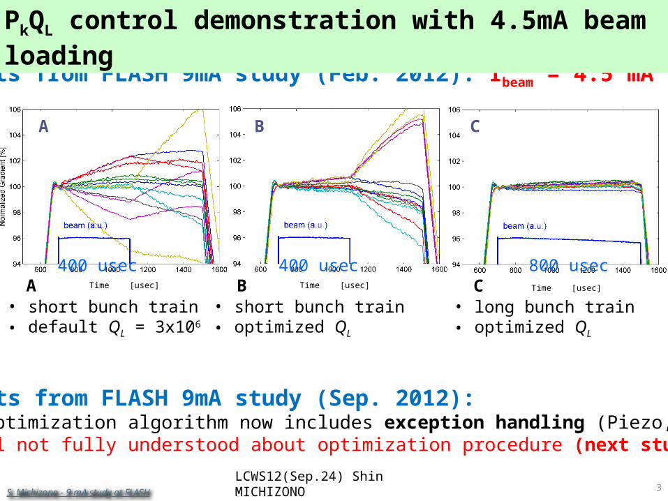
Time [usec] Time [usec] Time [usec]
A B C
ILC: 9mA @ FLASH: Gradient Study
Results from FLASH 9mA study (Feb. 2012): Ibeam = 4.5 mA
Results from FLASH 9mA study (Sep. 2012): QL optimization algorithm now includes exception handling (Piezo, Ql,…) Still not fully understood about optimization procedure (next study):
A B C• short bunch train• default QL = 3x10⁶
• short bunch train• optimized QL
• long bunch train• optimized QL
400 usec 400 usec 800 usec
LCWS12(Sep.24) Shin MICHIZONO3
PkQL control demonstration with 4.5mA beam loading
S. Michizono - 9 mA study at FLASH
R. CorsiniLCWS12 – Arlington 26 Oct. 2012
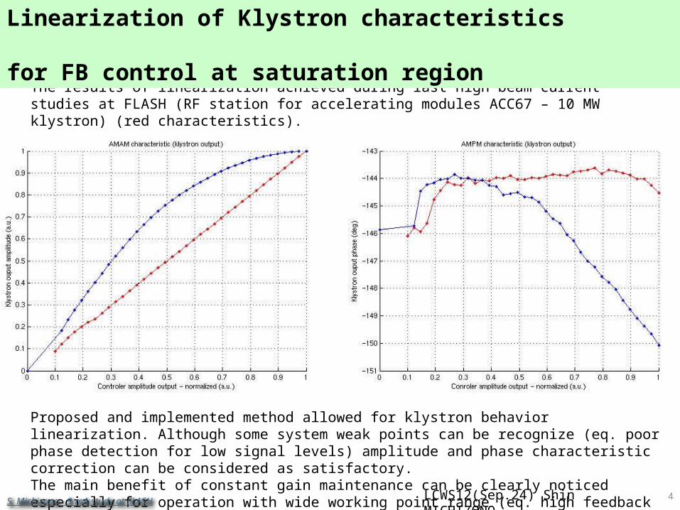
The results of linearization achieved during last high beam current studies at FLASH (RF station for accelerating modules ACC67 – 10 MW klystron) (red characteristics).
Linearization results
Proposed and implemented method allowed for klystron behavior linearization. Although some system weak points can be recognize (eq. poor phase detection for low signal levels) amplitude and phase characteristic correction can be considered as satisfactory.The main benefit of constant gain maintenance can be clearly noticed especially for operation with wide working point range (eq. high feedback gain control).
LCWS12(Sep.24) Shin MICHIZONO 4
Linearization of Klystron characteristics for FB control at saturation region
S. Michizono - 9 mA study at FLASH
R. CorsiniLCWS12 – Arlington 26 Oct. 2012
5
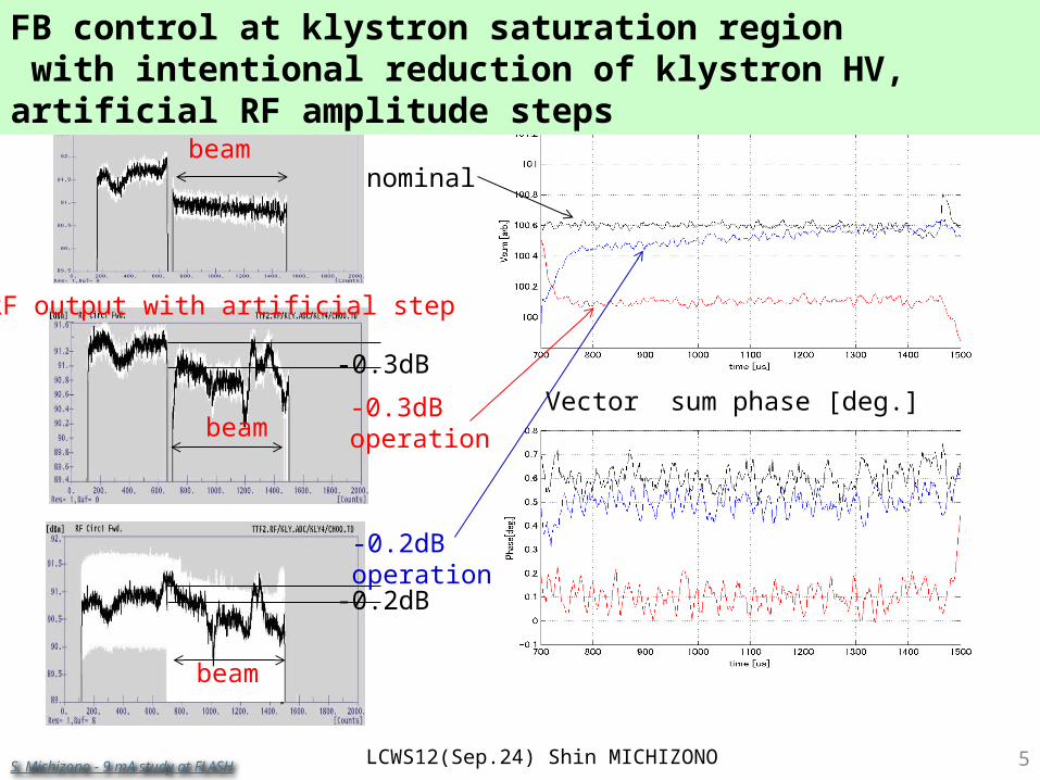
Measured stability
LCWS12(Sep.24) Shin MICHIZONO
-0.3dB
-0.2dB
beam
beam
beam
RF output with artificial step
nominal
-0.3dBoperation
-0.2dBoperation
Vector sum amplitude [arb.]
Vector sum phase [deg.]
FB control at klystron saturation region with intentional reduction of klystron HV, artificial RF amplitude steps
S. Michizono - 9 mA study at FLASH
R. CorsiniLCWS12 – Arlington 26 Oct. 2012
6
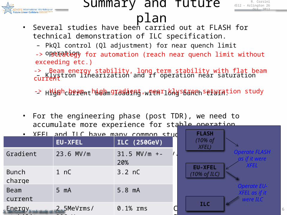
Summary and future plan• Several studies have been carried out at FLASH for technical demonstration
of ILC specification.– PkQl control (Ql adjustment) for near quench limit operation
– Klystron linearization and rf operation near saturation
– High current beam loading with long bunch train.
• For the engineering phase (post TDR), we need to accumulate more experience for stable operation.
• XFEL and ILC have many common study items because of the similar beam parameters.
• Further studies will be necessary.
LCWS12(Sep.24) Shin MICHIZONO
FLASH(10% of XFEL)
EU-XFEL(10% of ILC)
ILC
Operate FLASH as if it were XFEL
Operate EU-XFEL as if it were ILC
EU-XFEL ILC (250GeV)
Gradient 23.6 MV/m 31.5 MV/m +-20%
Bunch charge 1 nC 3.2 nC
Beam current 5 mA 5.8 mA
Energy stability 2.5MeVrms/20GeV(0.013%)
0.1% rms
-> strategy for automation (reach near quench limit without exceeding etc.)
-> Beam energy stability, long term stability with flat beam current
-> High beam, high gradient, near klystron saturation study
S. Michizono - 9 mA study at FLASH
R. CorsiniLCWS12 – Arlington 26 Oct. 2012
7
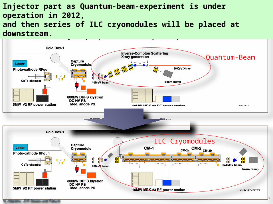
STF Accelerator Plan (2012- 2015)
Quantum-Beam
ILC Cryomodules
Injector part as Quantum-beam-experiment is under operation in 2012, and then series of ILC cryomodules will be placed at downstream.
H. Hayano - STF Status and Future plan
R. CorsiniLCWS12 – Arlington 26 Oct. 2012
8
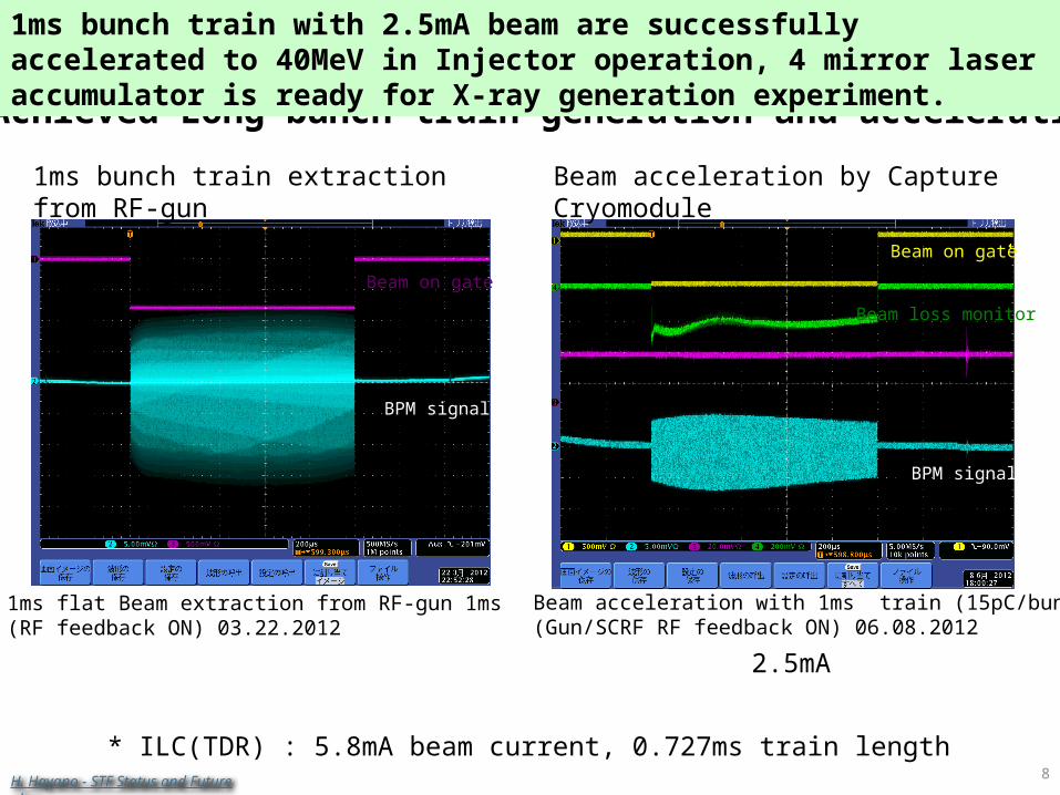
Beam acceleration with 1ms train (15pC/bunch)(Gun/SCRF RF feedback ON) 06.08.2012
Beam acceleration by Capture Cryomodule
1ms flat Beam extraction from RF-gun 1ms(RF feedback ON) 03.22.2012
1ms bunch train extraction from RF-gun
Achieved Long bunch train generation and acceleration
2.5mA
* ILC(TDR) : 5.8mA beam current, 0.727ms train length
BPM signal
BPM signal
Beam on gate
Beam on gate
Beam loss monitor
1ms bunch train with 2.5mA beam are successfully accelerated to 40MeV in Injector operation, 4 mirror laser accumulator is ready for X-ray generation experiment.
H. Hayano - STF Status and Future plan
R. CorsiniLCWS12 – Arlington 26 Oct. 2012
9
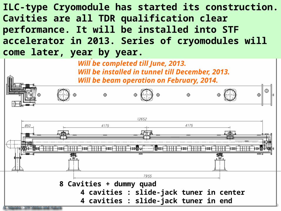
ILC design cryomodule : CM-1The fabrication started in this month.Will be completed till June, 2013.Will be installed in tunnel till December, 2013.Will be beam operation on February, 2014.
8 Cavities + dummy quad 4 cavities : slide-jack tuner in center 4 cavities : slide-jack tuner in end
ILC-type Cryomodule has started its construction. Cavities are all TDR qualification clear performance. It will be installed into STF accelerator in 2013. Series of cryomodules will come later, year by year.
H. Hayano - STF Status and Future plan
R. CorsiniLCWS12 – Arlington 26 Oct. 2012
10
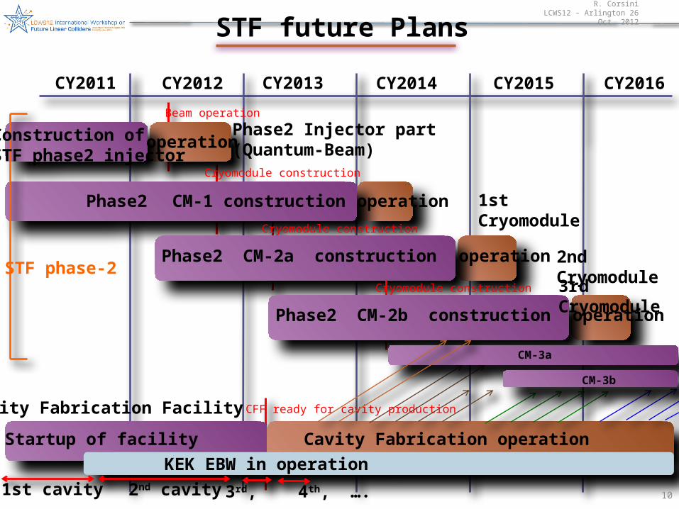
STF future Plans
CY2011 CY2012 CY2013 CY2014
STF phase-2
Phase2 Injector part(Quantum-Beam)
1st Cryomodule
Phase2 CM-2a construction
Construction ofSTF phase2 injector
Phase2 CM-1 construction
Cavity Fabrication Facility
Startup of facility Cavity Fabrication operation
operation
KEK EBW in operation1st cavity 3rd, 4th, ….
CY2015 CY2016
Beam operation
Cryomodule construction
CFF ready for cavity production
operationCryomodule construction
operation 2nd Cryomodule
Phase2 CM-2b construction
Cryomodule construction
operation
3rd Cryomodule
2nd cavity
CM-3a
CM-3b
R. CorsiniLCWS12 – Arlington 26 Oct. 2012
11
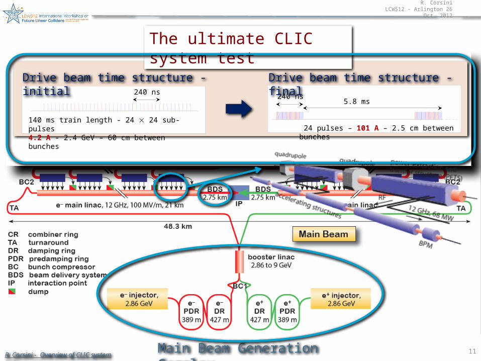
CLIC Layout at 3 TeV
Drive Beam Generation Complex
Main Beam Generation Complex
140 ms train length - 24 24 sub-pulses4.2 A - 2.4 GeV – 60 cm between bunches
240 ns
24 pulses – 101 A – 2.5 cm between bunches
240 ns5.8 ms
Drive beam time structure - initial Drive beam time structure - final
The ultimate CLIC system test
R. Corsini - Overview of CLIC system tests
R. CorsiniLCWS12 – Arlington 26 Oct. 2012
12
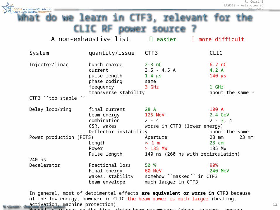
System quantity/issue CTF3 CLIC
Injector/linac bunch charge 2-3 nC 6.7 nCcurrent 3.5 - 4.5 A 4.2 Apulse length 1.4 ms 140 msphase coding samefrequency 3 GHz 1 GHztransverse stability about the same - CTF3 ``too stable ´´
Delay loop/ring final current 28 A 100 Abeam energy 125 MeV 2.4 GeVcombination 2 - 4 2 - 3, 4CSR, wakes worse in CTF3 (lower energy)Deflector instability about the same
Power production (PETS) Aperture 23 mm 23 mmLength 1 m 23 cmPower > 135 MW 135 MWPulse length 140 ns (260 ns with recirculation) 240 ns
Decelerator Fractional loss 50 % 90%Final energy 60 MeV 240 MeVwakes, stability somehow ``masked´´ in CTF3beam envelope much larger in CTF3
In general, most of detrimental effects are equivalent or worse in CTF3 because of the low energy, however in CLIC the beam power is much larger (heating, activation, machine protection)Needed tolerances on the final drive beam parameters (phase, current, energy stability...) are more stringent in CLIC – some could be are being demonstrated in CTF3 as well
A non-exhaustive list easier more difficult
What do we learn in CTF3, relevant for the CLIC RF power source ?
R. Corsini - Overview of CLIC system tests
R. CorsiniLCWS12 – Arlington 26 Oct. 2012
13
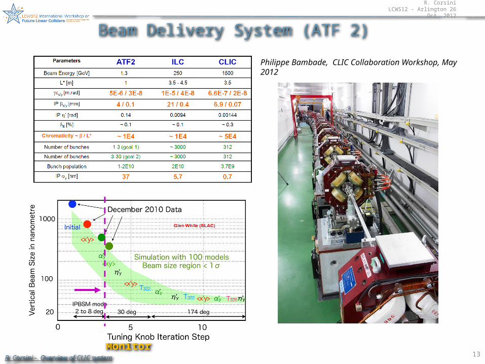
Beam Delivery System (ATF 2)
Philippe Bambade, CLIC Collaboration Workshop, May 2012
Shintake Monitor
R. Corsini - Overview of CLIC system tests
R. CorsiniLCWS12 – Arlington 26 Oct. 2012
14
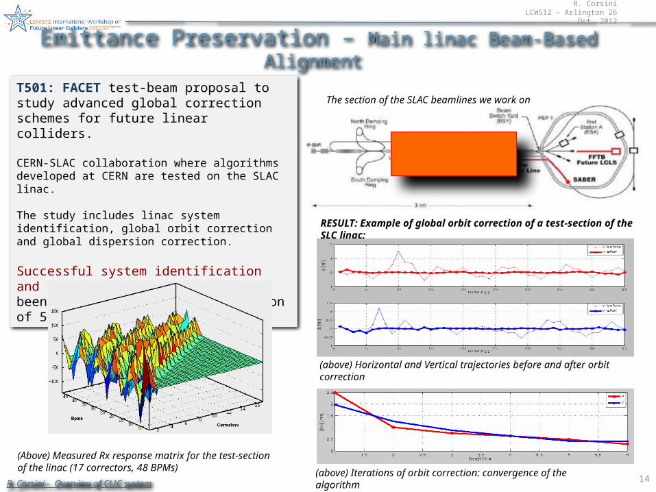
T501: FACET test-beam proposal to study advanced global correction schemes for future linear colliders.
CERN-SLAC collaboration where algorithms developed at CERN are tested on the SLAC linac.
The study includes linac system identification, global orbit correction and global dispersion correction.
Successful system identification and global orbit correction has been demonstrated on a test-section of 500 m of the linac.
(Above) Measured Rx response matrix for the test-section of the linac (17 correctors, 48 BPMs)
The section of the SLAC beamlines we work on
(above) Iterations of orbit correction: convergence of the algorithm
(above) Horizontal and Vertical trajectories before and after orbit correction
RESULT: Example of global orbit correction of a test-section of the SLC linac:
Emittance Preservation – Main linac Beam-Based Alignment
R. Corsini - Overview of CLIC system tests
R. CorsiniLCWS12 – Arlington 26 Oct. 2012
15
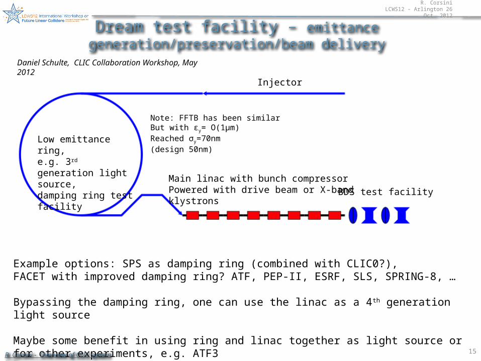
Dream test facility – emittance generation/preservation/beam delivery
Low emittance ring,e.g. 3rd generation light source,damping ring test facility Main linac with bunch compressor
Powered with drive beam or X-bandklystrons
BDS test facility
Injector
Example options: SPS as damping ring (combined with CLIC0?),FACET with improved damping ring? ATF, PEP-II, ESRF, SLS, SPRING-8, …
Bypassing the damping ring, one can use the linac as a 4th generation light source
Maybe some benefit in using ring and linac together as light source or for other experiments, e.g. ATF3
Note: FFTB has been similarBut with εy= O(1μm)Reached σy=70nm(design 50nm)
Daniel Schulte, CLIC Collaboration Workshop, May 2012
R. Corsini - Overview of CLIC system tests
R. CorsiniLCWS12 – Arlington 26 Oct. 2012
16
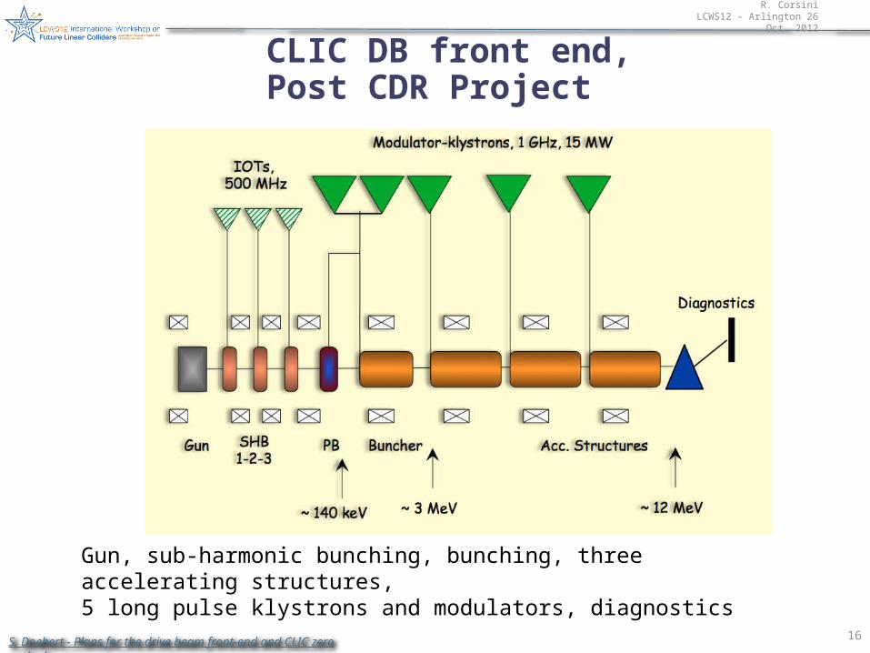
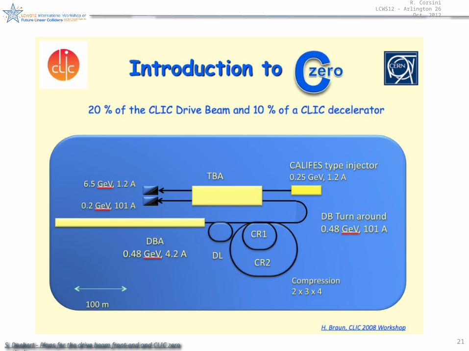
CLIC DB front end,Post CDR Project
Gun, sub-harmonic bunching, bunching, three accelerating structures,5 long pulse klystrons and modulators, diagnostics
S. Doebert - Plans for the drive beam front-end and CLIC zero outlook
R. CorsiniLCWS12 – Arlington 26 Oct. 2012
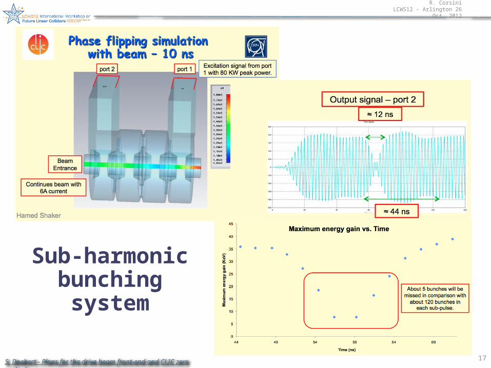
17S. Doebert - Plans for the drive beam front-end and CLIC zero outlook
Sub-harmonic bunching system
R. CorsiniLCWS12 – Arlington 26 Oct. 2012
18
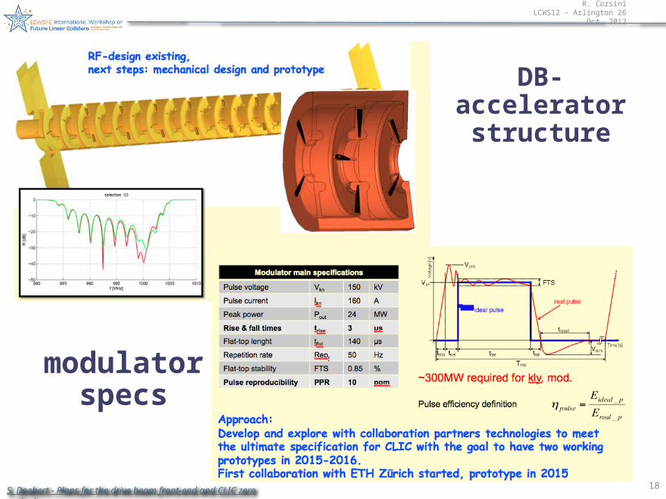
modulator specs
DB-accelerator structure
S. Doebert - Plans for the drive beam front-end and CLIC zero outlook
R. CorsiniLCWS12 – Arlington 26 Oct. 2012
19S. Doebert - Plans for the drive beam front-end and CLIC zero outlook
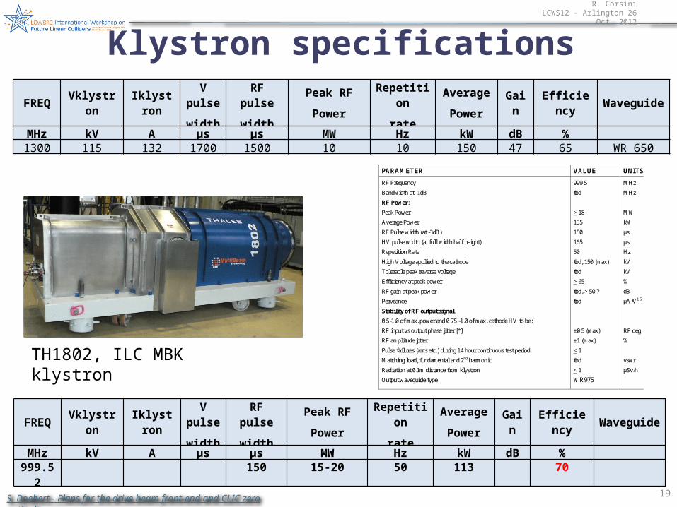
Klystron specifications
FREQ VklystronIklystro
n
V pulse
width
RF pulse
width
Peak RF
Power
Repetition
rate
Average
PowerGain
Efficiency
Waveguide
MHz kV A µs µs MW Hz kW dB %1300 115 132 1700 1500 10 10 150 47 65 WR 650
TH1802, ILC MBK klystron
FREQ VklystronIklystro
n
V pulse
width
RF pulse
width
Peak RF
Power
Repetition
rate
Average
PowerGain
Efficiency
Waveguide
MHz kV A µs µs MW Hz kW dB % 999.52 150 15-20 50 113 70
PARAMETER VALUE UNITS
RF Frequency
Bandwidth at -1dB
RF Power:
Peak Power
Average Power
RF Pulse width (at -3dB)
HV pulse width (at full width half height)
Repetition Rate
High Voltage applied to the cathode
Tolerable peak reverse voltage
Efficiency at peak power
RF gain at peak power
Perveance
Stability of RF output signal
0.5-1.0 of max. power and 0.75 -1.0 of max. cathode HV to be:
RF input vs output phase jitter [*]
RF amplitude jitter
Pulse failures (arcs etc.) during 14 hour continuous test period
Matching load, fundamental and 2nd harmonic
Radiation at 0.1m distance from klystron
Output waveguide type
999.5
tbd
> 18
135
150
165
50
tbd, 150 (max)
tbd
> 65
tbd, > 50 ?
tbd
±0.5 (max)
±1 (max)
< 1
tbd
< 1
WR975
MHz
MHz
MW
kW
μs
μs
Hz
kV
kV
%
dB
μA/V1.5
RF deg
%
vswr
μSv/h
R. CorsiniLCWS12 – Arlington 26 Oct. 2012
20
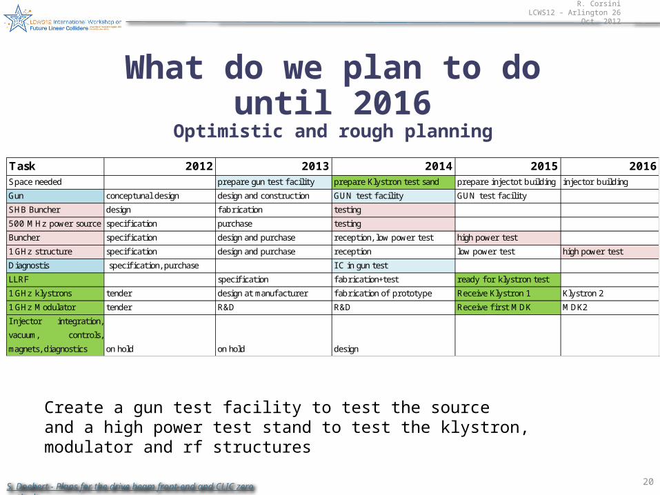
What do we plan to do until 2016Optimistic and rough planning
Task 2012 2013 2014 2015 2016Space needed prepare gun test f acility prepare Klystron test sand prepare injectot building injector building
Gun conceptunal design design and construction GUN test f acility GUN test f acility
SHB Buncher design fabrication testing
500 MHz power source specifi cation purchase testing
Buncher specifi cation design and purchase reception, low power test high power test
1 GHz structure specifi cation design and purchase reception low power test high power test
Diagnostis specifi cation, purchase I C in gun test
LLRF specifi cation fabrication+test ready for klystron test
1 GHz klystrons tender design at manufacturer fabrication of prototype Receive Klystron 1 Klystron 2
1 GHz Modulator tender R&D R&D Receive fi rst MDK MDK2
I njector integration,
vacuum, controls,
magnets, diagnostics on hold on hold design
Create a gun test facility to test the sourceand a high power test stand to test the klystron, modulator and rf structures
S. Doebert - Plans for the drive beam front-end and CLIC zero outlook
R. CorsiniLCWS12 – Arlington 26 Oct. 2012
21S. Doebert - Plans for the drive beam front-end and CLIC zero outlook
R. CorsiniLCWS12 – Arlington 26 Oct. 2012
22
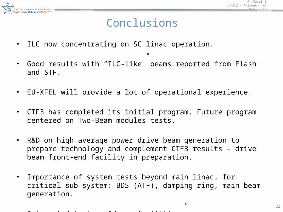
Conclusions
• ILC now concentrating on SC linac operation.
• Good results with “ILC-like” beams reported from Flash and STF.
• EU-XFEL will provide a lot of operational experience.
• CTF3 has completed its initial program. Future program centered on Two-Beam modules tests.
• R&D on high average power drive beam generation to prepare technology and complement CTF3 results – drive beam front-end facility in preparation.
• Importance of system tests beyond main linac, for critical sub-system: BDS (ATF), damping ring, main beam generation.
• Integrated tests > “dream facilities”…