Embed Size (px)
Citation preview

This document was revised December 2011 for use in University of Minnesota Quality Count$ programs This material is intended for educational use only and may not be altered in any way but may be reproduced with permission of University of Minnesota Extension Dairy Team.
R-EF-11: Stray Voltage Problems with Dairy Cows H.A Cloud, R.D Appleman, and R.J Gustafson Minnesota Extension Service, University of Minnesota, St. PaulAG-BU-1359, Revised 1987
CONTENTS PageIntroduction ......................................................................................................................................................... 1 Symptoms .......................................................................................................................................................... 1 Behavior Modification .................................................................................................................................. 1 Milking Characteristics ................................................................................................................................ 2 Production Performance ............................................................................................................................. 2 Potential Stray Voltage Sources ....................................................................................................................... 2 Primary Neutral Current External to the Farm ............................................................................................ 4 Primary Neutral Current From On-Farm Loads .......................................................................................... 4 Secondary Neutral Current in the Farmstead Wiring System ............. ....................................................... 4 Fault Currents on Equipment Grounding Conductors .. .............................................................................. 6 Improper Use of Neutral Conductor ............................................................................................................ 6 Grounded Fault Currents ............................................................................................................................ 7 Induced Voltages ........................................................................................................................................ 7When can Stray Voltage Be a Problem? . ......................................................................................................... 8 Standardized Measurements . ........................................................................................................................... 9 Screening Procedure ...... ................................................................................................................................ 10Diagnostic Procedures .......... .......................................................................................................................... 12 Basic Data . ................................................................................................................................................ 12 Voltage Testing Set-up ........ ..................................................................................................................... 12Detailed Diagnostic Procedures ...................................................................................................................... 14Solutions to the Problem ................................................................................................................................. 17 Voltage Reduction ..................................................................................................................................... 17 Elimination or Reduction of Sources . ................................................................................................. 17 Active Voltage Suppression ................................. .............................................................................. 18 Gradient Control ....... ................................................................................................................................. 19 Equipotential Planes . .......................................................................................................................... 19 Transition Ramps .............. ................................................................................................................. 19 Isolation ................ ..................................................................................................................................... 20 Whole Farm Isolation .......................................................................................................................... 20 Available Devices at Transformer ................................................................................................ 20 Isolating Transformers .................................................................................................................. 21 Single Building Service Isolation ........................................................................................................ 22
APPENDIXES .................................................................................................................................................. 23I. Testing Equipment II. Electrical Grounding III. References for Further Study

-- Minnesot a Extension Service • University of Minnesota
STRAY VOL AGE PROBLEMS WI H DA RY COWS
H. A. Cloud, R. D. Appleman, and R. J. Gustafson
Figure 1. A dairy cow subjected to a neutral-to-earth IN-E) voltage
SECONDARY NEUTRAL FROM
THE TRANSFORMER t1-- -,
I BA N I I SERVICE I ANY VOLTAGE ON THE GROUNDED
NEUTRAL SYSTEM IS READ BY THEI ENTRANCE VOLTMETER AS A NEUTRAL-TOI EARTH VOLTAGE
"ISOLATED" GROUND ROD
AS A REFERENCE \
COW IN ------i- *IiiI.. CONTACT WITH GROUNDED NETWORK WET CONCRETE
.. FEET IN .,.,
GOOD CONTACT WI T H EARTH - "TRUE" GROUND
H. A . Cloud is an extension agri cultural engineer; R. D. Appleman is an extension animal AG-BU-1359 scientist, dairy management, and R. J . Gustafson is a professor of Agricultural Engineering. Revised 1987 All authors are at the University of Minnesota.
--
STRAY VOLTAGE PROBLEMS WITH DAIRY COWS
INTRODUCTION Stray voltages are causing serious problems in certain dairy operations and other confinement livestock systems. Dairymen are losing milk production and are experiencing cow behavior and cow health problems due to small electrical currents passing through the cows' bodies. The voltages are known by several names, including tingle voltage, neutra I-to-ea rth (N-E) voltag e, neutral-to-ground voltage, and extraneous voltage. The problem stems from excessive voltage between two animal contact points.
The concept of stray voltage is relatively simple electrically, though the sources can be varied and complex. These voltages may be caused by poor or faulty wiring, faulty equipment, improper grounding, or they may result from the small voltages required to move current through the grounded neutral system. As farm operations increase in size and sophistication, as electrical wiring systems become obsolete or deteriorate, and as electrical loads on rural distribution systems increase, it is likely that stray voltage problems will continue to exist. However, we believe that with a good understanding of: 1) stray voltage sources and their interactions and 2) the sensitivity of animals to electrical currents, stray voltage problems can be analyzed and corrected in existing facilities and prevented in new constructions. This publication is intended to explain the stray voltage problem, describe how to determine if potential for a problem exists in your dairy operation, describe how to determine sources of the problem, and give recommendations on how to correct the problem.
SYMPTOMS Reactions of animals subjected to stray voltages vary, depending on the pathway through animals and the magnitude of voltage. There are three general classifications of symptoms, related to : 1) behavior modification, 2) milking characteristics, and 3) production performance. It must be remembered, however, that many factors otherthan stray voltages may cause herd behavior or health and production problems. These factors include management and cow handling methods, nutritional disorders, mastitis control methods, sanitation, and disease. A careful analysis of all possible causes is necessary if proper corrective procedures are to be found.
Behavior Modification
Both controlled research and observation on problem farms clearly shows that animals subjected to stray voltages are likely to exhibit a change in behavior . The following are the most common symptoms.
1. Cows Excessively or Unusually Nervous in the Milking Parlor or Stall Barn at Milking Time This trait often is characterized by cows dancing or stepping around while in the stall. Ifthis behavior is caused by stray voltage, it is usually due to a voltage between the stall pipes (which the cow touches) and the concrete floor (on which the cow is standing). However, dairy farmers are reminded that cows may become nervous for other reasons, such as malfunctioning milking equipment (too high vacuum or inappropriate pulsation ratios) or operator abuse. Even a change in milking routine may result in cows temporarily appearing nervous.

2. Cows must be Chased into the Parlor and/or Rapid Flight from the Parlor When cows are subjected to stray voltages in the parlor stalls, they soon become reluctant to enter the parlor. In extreme cases, nearly all cows have to be driven into the parlor and they may have a tendency to "stam pede" out upon release. But again, this symptom is not specific to stray voltage problems because cows may be trained to expect the parlor operator to chase them into the milking stalls.
3. Increased Number of Defecations and/or Urinations in the Milking Parlor It is well documented that nervous cattle will excrete body wastes more frequently. These phenomena may be caused by a stray voltage problem, or other causes, including operator abuse, presence of strangers, change to green feed from dry roughages, etc.
4. Reluctance of Animals to Consume Water or Feed Reduced intake of water and/or feed due to stray voltage problems may occur with any cla ss of livestock. Documented cases include dairy and beef cattle, swine, and poultry. The problem may be general throughout the farmstead, or only at a specific waterer or feeding location. Generally speaking, higher voltages are required to limit water or feed consumption than to alter the other behavioral characteristics discussed previously. A rather specific symptom indicative of a probable stray voltage problem is the uncharacteristic "Iapping of water" during animals' attempts to meet their demand for water. Farmers must recognize, too, there are other causes for these symptoms, especially a sudden change in water quality, the feeding of spoiled or unpalatable feeds, sickness, etc.
Milking Characteristics
Poor milk letdown, incomplete milkout (leaving abnormal amounts of residual milk in one or more quarters), and increased milking time are common
symptoms expressed by dairy farmers having stray voltage problems. The mechanism of how this occurs isn't fully understood. Researchers haven't been successful in identifying any significant hormonal changes. However, researchers have demonstrated that the milking machine hose, even under high flow rates, is not a likely pathway for electrical currents to the cow.
5. Poor Milk Letdown and Incomplete or Uneven Milkout The number of cows affected and the severity of the milk letdown problem appears to be dependent on the level of stray voltage present. When affected cows are moving or stepping about during the milking process, it is difficult to keep the milking unit properly aligned and adjusted to provide an even weight distribution necessary to promote fast, effective milkout. On the other hand, a damaged teat canal may result in one qua rte r bei ng co ns istently slow to milk out.
6. Increased Milking Time If the stray voltage problem is severe enough to affect cows' behavior, milkout may be influenced. This problem can result in additional time needed for milking.
Production Performance
Although stray voltage has not been shown to have a direct physiological effect on cows, severe behavioral responses will complicate management practices. As a result, labor efficiency and profitability may be lowered.
7. Increased Somatic Cell Count and More Clinical Mastitis lViastitis, whether clinical or subclinical (indicated by high somatic cell counts), is the result of a bacterial infection of the mammary gland. Such infections aren't directly caused by stray voltages. However, if cows' behavior is modified, and if the milking routine is altered because of the change in cows' behavior, what may result is a less satisfactory milking performance, increased somatic cell counts, and more clinical mastitis.
8. Lowered Milk Production If cows drink less water, consume less food, or become mo re mastitic, they are likely to produce less milk. Whether or not milk production will be adversely affected by stray voltage depends on the extent to which the cows' behavior is altered and how management compensates. When stray voltage problems were corrected, milk production per cow on some farms increased as much as 3,500 pounds per cow per year. On the other hand, improvement in milk production is not always apparent after a stray voltage problem is corrected.
In summary, stray voltage problems alter animal behavior, and may influence milking characteristics or affect production performance. If unacceptable levels of stray voltage exist, take corrective action. Remember that many non-electrical causes can produce the same symptom s. W ith carefu l analysis of all possible causes, proper corrective procedures can be found.
Attempts have been made to associate the problems of unthrifty and unhealthy animals, poor reproduction, and weak calves with stray voltage. The failure of controlled research to find a direct physiological effect in animals subjected to stray voltages, and the absence of documented case studies demonstrating a marked improvement in these traits upon correction of an existing problem, leads to the conclusion that there is no direct and causal relationship.
POTENTIAL STRAY VOLTAGE SOURCES Stray voltage problems arise from relatively simple electrical conditions. As an example, figure 1 (front cover) shows a dairy cow "bridging the gap" between an electrically grounded water cup and "true earth." Ifthe meter indicates voltage of sufficient magnitude between the reference ground (representing "true earth") and the electrically grounded watering system, it may force enough current
2

Figure 2. The grounded neutral network (in red) on a single-phase distribution line
FARM SERVICE PRIMARY "HOT" TRANSFORMER E!;!~~NCE
PRIMARY NEUTRAL
GROUND RODS ALONG THE LINE
through the cow's body to cause serious problems. However, there are many variables which will cause considerable variation from farm to farm and within a particu I a r bu i I ding. These va riabies require both an understanding of the voltage sources and electrical pathways to the animal to assure correct problem diagnosis.
Any electrical condition which creates a large enough voltage between any two animal contact points may create a stray voltage problem. There are numerous sources of these low level voltages. However, they are normally associated with: 1) electrical fault conditions on either the farmstead wiring or the distribution system, 2) inherent neutralto-earth voltages on multigrounded distribution systems resulting from system loading, 3) voltage drops on secondary neutrals resulting from 120-volt load imbalance, and 4) induced
- - - ---- L~"HOT;:-__F~ ~;.---l
PRIMARY NEUTRAL
GROUND ROD AT TRANSFORMER
PRIMARY NEUTRA
SECONDARY NEUTRAL I I
L z "HOT" I I -----~"::... !j-l I
...--'
ELECTRICAL BOND BETWEEN PRIMARY AND SECONDARY NEUTRAL
voltage on ungrounded equipment.
Figure 2 is a simplified diagram of a multi-grounded, singlephase distribution system serving a farmstead . In a multigrounded system, the primary or utility system neutral conductor is grounded at least four times per mile along the line and at each transformer. The on-farm or secondary neutral is grounded at thefarm service and at each building service entrance. (Note: System grounding and equipment grounding are described in more detail in a later section.) At the transformer the primary neutral is electrically bonded to the secondary neutral. These grounded and bonded primary and secondary neutrals (as shown by the solid lines in figure 2) make up a complex network termed the grounded neutral system.
Every part of the grounded neutral system, including con-
GROUNDING TERMINAL BLOCI<
I IL2 ILl
I-~ - ~l I BARN I I SERVICE IENTRANCE
~••I
----120 VOLT CIRCUITS (Grounding Conductor Not Shown)
GROUNDED STANCHION OR PARLOR PIPE
ductors, the connections, the earth, and the contact between the ground rods and earth, has some resistance to the flow of electric current. Due to these resistances, whenever there is a current in the neutral system a voltage exists between it and earth. These voltages are reflected, at varying levels, to all parts of the interconnected system. They exist as neutral-toearth (N-E) voltages and if large enough will cause a perceptible current flow through an animal bridging the gap between the neutral system and the earth.
In the following examples, stray voltages associated with the distribution system and the farmstead wiring system are separated into several distinct categories. Unfortunately, in the field the contribution from all sources will be superimposed and their interactions can make an accurate diagnosis difficult. If the contribution from each source can be
OTHER REQUIRED GROUNDING CONNECTIONS SUCH AS WATER PIPES ARE NOT SHOWN
3

Figure 3. Neutral-to-earth voltage on a farm due to other loads on the same fine
---.,-------I I SECONDARY I I
L,
ARROWSL2 FLOW OF CURRENT
OTHER LOADS ON THE SAME DISTRIBUTION SYSTEM - ANY LOAD IS ACCOMPANIED BY A CORRESPONDING PRIMARY NEUTRAL CURRENT
clearly identified and measured, the diagnosis is easy and the appropriate corrective measures can be readily determined. However, a good understanding ofthe sources and their interactions is necessary. An "isolated" ground rod is used as a reference when measuring N-E voltages . If one lead of a voltmeter is attached to the service entrance g round at the barn, as shown in figure 3, and the other lead is attached to the "isolated" reference rod, it will read the N-E voltage existing on the network at this location . The location and use ofthis "isolated" reference rod and voltmeter is discussed in the section entitled "Standardized Measurements." In this position the voltmeter reads the maximum voltage to which a cow could be subjected. As described earlier, actual voltage across the animal may vary widely depending on conditions in the barn. The following are potential stray voltage sources.
NEUTRAL
L; t L,' 1.- -., I BARN I I SERVICE I IENTRANCE I I I
INDICATE POSSIBLE L..: - _--.I PRIMAR Y NEUTRAL VOLTMETER WILL FROM OTHER TO CHANGES INI
FARMS DEPENDING ON LOAD ~ RELATI VE RESISTANCES 6 LOADS
1. Primary Neutral Current External to the Farm
As the current in the distribution neutral increases due to increased load on other parts of the single phase tap or the imbalance current in three-phase feeder increases, the primary N-E voltage will increase. This can be reflected to a greater or lesser deg ree to the problem farm through the pri mary-secondary neutral interconnection at the transformer (figure 3). This contribution can be determined at any specific time by measuring N-E voltages on the problem farm with the main farm disconnect open (neutral intact) .
2. Primary Neutral Currents from On-Farm Loads
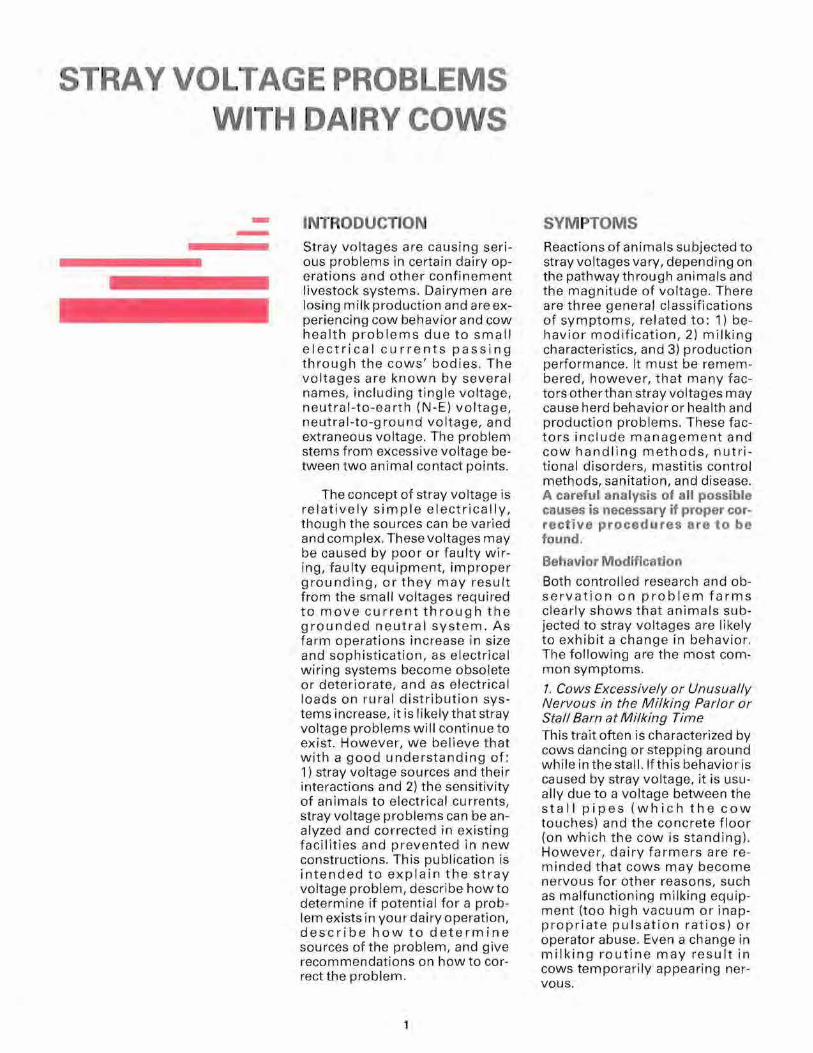
As the electrical load on the distri bution transformer of the problem farm increases, the increase in primary neutral current will generally result in increased pri mary N-E voltages which will be reflected to the farmstead grounding system through the in-
RESPOND LINE
~
VOLT METER
terconnection at the transformer (figure 4). In the case of a farm near a three-phase feeder, it is possible for an increase in onfarm load to improve the balance on the feeder and thereby reduce the primary N-E voltage. A common misconception is to relate an increase in I\J-E voltage associated with the operation of equipment on the farm to an on-farm problem. An increase in N-E voltage with the operation of "clean" 240-volt loads is a pri mary N-E voltage (or off-farm problem created by an on-farm electrical load).
3. Secondary Neutral Current in the Farmstead Wiring System
A current in any portion ofthe secondary neutral due to imbalance in 120-volt loads (load connected to L, does not equal load connected to L2 ) is accompanied by a voltage drop (figure 5).
Since the secondary neutral current may be either in-phase or
4
--- --
Figure 4. Increase in neutral·to·earth voltage due to increasing loads on the same farm
TRANSFORMER L,
-- NEUTRAL
L2 t L,
,t- ~,
I I BARN I
ANY INCREASE IN FARM Jl I SERVICE ILOAD IS ACCOMPANIED BY IENTRANCEIAN INCREASE IN PRIMARY NEUTRAL CURRENT I I
L.: _ _
TO
J VOLTMETER WILL RESPOND
CHANGES IN LINE LOAD~
IV~TIANY INCREASE IN PRIMARY METERNEUTRAL CURRENT IS ACCOMPANIED BY AN t INCREASE IN N - E VOLTAGE AT THE BARN SERVICE ENTRANCE
SERVICE ENTRANCE GROUND ROD
Figure 5. Neutral-to-earth voltage created by the voltage drop in the secondary neutral to the barn
TRANSFORMER
II ~~~~~~~~N~E~U~T~R~A~L~ L2 t L I 120-VOLT LOADS CREATE
IMBALANCE CURRENT IN SECONDARY NEUTRAL-
ANY CURRENT CHANGES ON SECONDARY NEUTRAL CHANGES N - E VOLTAGE AT THE BARN
,t- , I BARN I ISERVICE u..--===-------t====~
IENTRANCEI r;::::::::::::::::::j:~~~~ I II I L.: J
~ VOLTMETER RESPONDS TO CHANGES IN SECONDARY NEUTRAL CURRENT
= VOLT
METER
SERVICE ENTRANCE GROUND ROD
5

Figure 6. Added neutral-to-earth voltage created by a fault to grounded equipment
VOLTAGE DROP ON = GROUNDING CONDUCTOR
- -FAULT CURRENT
EQUIPMENT GROUNDING CONDUCTOR
NEUTRAL CONDUCTOR IV~TI
VOL METER "3 ~
------~<--
IV~TI METER "2 METER" I
1800 out-of-phase with the primary neutral, the phase relationship between this voltage source and that due to the off-farm or primary neutral source must be considered. A voltage drop created by imbalance current in-phase with the primary will increase the N-E voltage at the barn. On the other hand, if the imbalance current is out-of-phase with the primary, the N-E voltage at the barn may decrease.
4. Fault Currents on Equipment Grounding Conductors
Anyfaultcurrentflowing in equipment grounding conductors will create a voltage drop on the grounding conductor (figure 6). It will also affectthe cu rrent balance in the secondary neutral to that service. Most of the voltage drop will appear as a voltage between the faulty equipment and earth and will access the animals through any conductive equipment in electrical contact with the faulty equipment. The equipment-to-earth voltage is indicated by voltmeter #1 in figure 6. The voltage drop on the equipment
grounding conductor is the difference between voltmeter #1 and voltmeter #2 and can be measured as indicated by voltmeter #3. With no faults and proper equipment grounding the two voltmeters will read the same. If there is a voltage drop on the secondary neutral, it can either add to or subtract from the N-E voltage at the service entrance. Any difference between the two readings is indicative of either improper equipment grounding or a current in the grounding conductor.
If the fault current is not enough to open the branch circuit protection it may go undetected for some time. Short term intermittent faults can be particularly troublesome. For example, a 20ampere fault current in 50 feet of #12 copper conductor results in a voltage drop of 1.8 volts. Without proper equipment grounding this would create a hazardous condition. This emphasizes the importance of maintaining low resistance equipment grounding. Corrosive environments in livestock facilities can deteriorate
electrical connections and increase stray voltage problems as a result offault currents.
5. Improper Use of the Neutral Conductor on 120-volt Equipment as a Grounding Conductor or Interconnection of the Neutral and Grounding Cond uctor at th e Eq ui pm ent Location
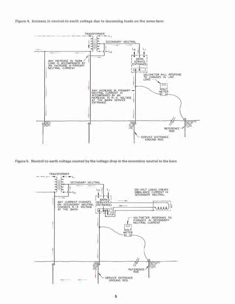
In agricultural wiring systems, the neutral (grounded conductor) and the equipment grounding conductors are bonded together at the building service entrance (figure 7). However, all feeders and branch circuits beyond the building main service must maintain the neutral and equipment grounding separately.
Reportedly, the practice of neutral and equipment grounding conductor interconnection beyond the service entrance is a relatively common practice where the electrical code requirements are not enforced. This is a violation ofthe code and may create a stray voltage problem in addition to an increased potential
6
for a hazardous condition. In this situation the load current will be carried by the grounding conductor (where it is improperly used as the neutral), or by the grounding conductor in parallel with the neutral (where they are interconnected at the device). The additional stray voltage component is equal to the voltage drop for the neutral current between the service entrance neutral bar and the equ ipment. This component can either add to or subtract from the existing N-E voltage at the service entrance. This is particularly im portant in circuits with 120-volt motor starting surges since currents may be large.
6. Ground Fault Currents to Earth Through Faulty Insulation on Energized Conductors or Improperly Grounded Equipment
Leakage currents to earth from an energized secondary conductor (fault currents) must return to the center tap of the distribution transformer, thereby creating a neutral-to-earth voltage. Signifi cant fault cu rrents to earth are due to insulation breakdown on a conductor or in ungrounded equip ment in contact with earth (figure 8) . If such a fault develops, the seriousness of the situation de pends on the electrical resistance ofthe retu rn path from the fau Itto the grounded neutral system . Dangerous step and touch potentials can be present in the area of the fault. These could be at a potential which creates a lethal hazard.
Fault currents to earth returning to the distribution transformer through the grounded neut ral network will be superimposed on the primary neutral load current. I\I-E voltages will be additive if leakage current is from the out-ofphase leg of the secondary; subtractive iffrom the in-phase leg.
7. Induced Voltages on Electrically Isolated Conductive Equipment
It is possible for induced voltages to exist on isolated conductive equipment. In dairy facilities, electrically isolated water lines, milk pipelines, and vacuum lines
Figure 7. Neutral and equipment grounding of 120-volt equipment
:~-J-c, ~ I t I
III BARN SERV ICE I ENTRANCE I
I t I I I HOT
~~~.~--~~~ I LOAj? CURRENT L __
-FAULT CURRENT
CO RRECTLY CONNECTED 120 - VOLT BRANCH CIRCUIT
IC~ -J-' " C
I BARN I SERVICE I ENTRANCE I
I I II ~-r~ ~__-===~.~____-F~~~~I HOTI LOAD CURRENT
L __ _ -::.. _I=~~==-~==~~--~~~~
IMPROPER USE OF THE NEUTRAL AS A GROUNDING CO NDU CTOR
r~J -C ' ~ I rr I BARN
SERVI CE I ENTRANCE
I t HOTI
I LOAD CURRENT..L_ -FAULT CURRENT
IMPROPE RLY INT ERCONNECTED NEUTRAL AND GROUND
7

Figure 8. Leakage current to earth from an energized secondary conductor Sig nificant stray voltage prob
FARMSTEAD MAIN SERVICE
•
HOT
BARN SERVICE ENTRANCE
HOT
NE UTRAL
INSULATION BREAKDOWN
may exhibit a voltage relative to other points when measured with a very high impedance voltmeter. A common sou rce in stanchion barns are high voltage cow trainers running parallel to the lines, Any other isolated conductive equipment in proximity to an electrical source can show a potential difference also,
Due to the high impedance of such a voltage source, the current producing capabilities are very small and rarely capable of producing problem level currents. However, ifthe equipment is electrically well isolated (not grounded) and has sufficient electrical capacitance, it may provide a capacitive discharge of suffi cient energy to cause a stray voltage problem when an animal shorts it to ea rth.
W HEN CAN STRAY VOLTAGE BE A PROBLEM? On any electrical distribution system it is necessary to have some voltage existing between all electrically grounded equipment and the earth. These N-E voltages exist on all grounded motor casings, water pipes, sinks, bulk tanks, stall and stanchion pipes, feeders, milking equipment, etc, As described earlier, these voltages wi II
WITH CURRENT LEAKAGE TO EARTH FROM A HOT CONDUCTOR
force an electric current through any conductor, including a cow's body, providing a pathway to earth,
Since all metal pipes and feeders should be connected to the neutral system for safety reasons, th ere are a number of possible co ntact points between which these N-E voltages may cause a current flow through the cow's body. Some of those contact points are the feeder, waterer, metal stanchion or stall, metal grate, concrete floo r on which the cow stands, and concrete parlor floor on which the operator stands.
Cows may react differently depending on which parts of their bodies are in contact with the grounded neutral network and which parts are communicating with earth or "true" ground, Research has established the "mouth-all hooves" pathway to bethe lowest resistance pathway; hence, a sensitive one at relatively low voltages. Furthermore, this is a common pathway for current to flow through the cow's body. A cow's hooves may be in contact at one potential (earth or concrete) and her mouth in contact with a metal surface at a significantly dif ferent potential (waterer, metal feeder, or stall piping).
8
lems may occur when voltages accessing dairy cows through the "mouth-all hooves" pathway exceed 1.0 volt. Below 0,7 volt, the problems are usually min ima l. The authors recommend continued monitoring when measured voltages reach the D.5-volt level. A reasonable and atta inable goal on f arms nee ding correctio n w ould be to m ainta in neutral voltages on t he farm grounding system below 0.35 volt.
Dairy cattle are sometimes subjected to low voltage shocks as they enter the milking parlor or holding pen. Because the resistance of the "front-rear hooves" pathway is approximately twice that of the "mouth-all hooves" pathway, it requires a 2.0-volt step potential shock to produce the same response as a 1.0-volt "mouth-all hooves" shock.
Animals vary in their sensitivity to stray voltages. Cows with a poor hoof structure walking on injured soft tissue are likely to be more sensitive, On the other hand, milking equipment, and the teat end, isn't a likely path of problem currents. Milk isn't a particularly good conductor of electricity, and the resistance of the milk hose from the milk line to the machine claw is inversely proportional to milk flow rate. Thus, in spite ofthe fact that observed cow behavior modifications are frequently associated with the milking process, it requires more than 25 volts on the milk line for cows to obtain perceptible currents through this pathway.
Cows appear to be more responsive to the initial exposure to current than "static (steady) currents associated with low voltages." Several short duration shocks may be more bothersome to animals than a longer shock of the same'intensity. Finally, an irregular and intermittent shocking pattern is more likely to be disruptive. Cows appear to be bothered as much, or more, by the anticipation of the shock as the shock it self.
0.75
STEEL PLATE ON WETTED FLOOR
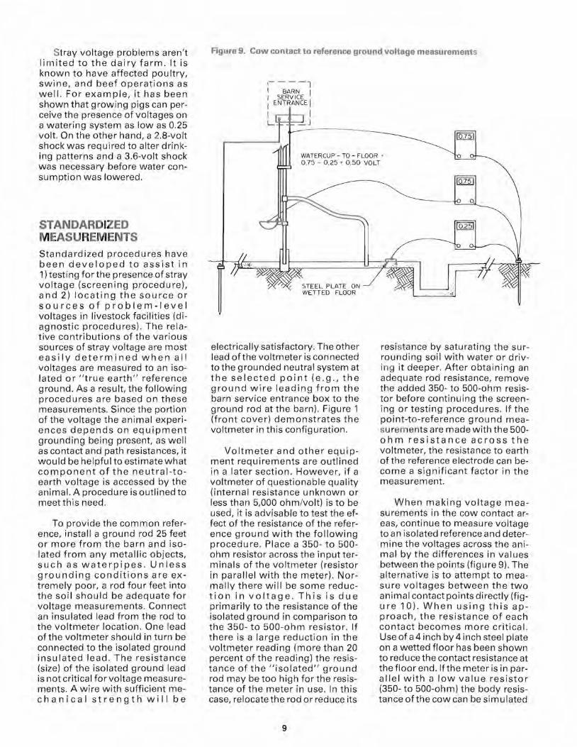
Stray voltage problems aren't limited to the dairy farm. It is known to have affected poultry, swine, and beef operations as well. For example, it has been shown that growing pigs can perceive the presence of voltages on a watering system as low as 0.25 volt. On the other hand, a 2.8-volt shock was required to alter drinking patterns and a 3.6-volt shock was necessary before water consumption was lowered.
STANDARDIZED MEASUREM ENTS Standardized procedures have been developed to assist in 1) testi ng for the presence of stray voltage (screening procedure), and 2) locating the source or sources of problem-level voltages in livestock facilities (diagnostic procedures). The relative contributions of the various sources of stray voltage are most easily determined when all voltages are measured to an isolated or "true earth" reference ground. As a result, the following procedures are based on these measurements. Since the portion of the voltage the animal experiences depends on equipment grounding being present, as well as contact and path resistances, it would be helpful to estimate what component of the neutral-toearth voltage is accessed by the animal. A procedure is outlined to meetthis need.
To provide the common reference, install a ground rod 25 feet or more from the barn and isolated from any metallic objects, such as waterpipes . Unless grounding conditions are extremely poor, a rod four feet into the soil should be adequate for voltage measurements. Connect an insulated lead from the rod to the voltmeter location. One lead of the voltmeter should in turn be connected to the isolated ground insulated lead. The resistance (size) of the isolated ground lead is not critical for voltage measurements. A wire with sufficient mechanical strength will be
Figure 9. Cow contact to reference ground voltage measurements
1- ---l I BARN I I SERVICE I ENTRANCE I I I L _J
WATERCUP - TO - FLOOR' - 0.25 ' 0.50 VOLT
electrically satisfactory. The other lead ofthe voltmeter is connected to the grounded neutral system at the selected point (e.g., the ground wire leading from the barn service entrance box to the ground rod at the barn). Figure 1 (front cover) demonstrates the voltmeter in this configuration.
Voltmeter and other equipment requirements are outlined in a later section. However, if a voltmeter of questionable quality (internal resistance unknown or less than 5,000 ohm/volt) is to be used, it is advisable to test the effect of the resistance of the reference ground with the following procedure. Place a 350- to 500ohm resistor across the input terminals of the voltmeter (resistor in parallel with the meter). Normally there will be some reduction in voltage. This is due primarily to the resistance of the isolated ground in comparison to the 350- to 500-ohm resistor. If there is a large reduction in the voltmeter reading (more than 20 percent of the reading) the resistance of the "isolated" ground rod may be too high for the resistance of the meter in use. In this case, relocate the rod or reduce its
resi stance by saturating the surrounding soil with water or driving it deeper. After obtaining an adequate rod resistance, remove the added 350- to 500-ohm resistor before continuing the screeni ng 0 r testi ng p roced u res . If the point-to-reference ground measu rem ents are made with the 500ohm resistance across the voltmeter, the resistance to earth of the reference electrode can become a significant factor in the measurement.
When making voltage measurements in the cow contact areas, continue to measure voltage to an isolated reference and determine the voltages across the animal by the differences in values between the points (figure 9). The alternative is to attempt to measure voltages between the two animal contact points directly (figure 10). When using this approach, the resistance of each contact becomes more critical . Use of a 4 inch by4 inch steel plate on a wetted floor has been shown to reduce the contact resistance at the floor end. If the meter is in parallel with a low value resistor (350- to 500-ohm) the body resistance ofthe cow can be simulated
9

SCREENING PROCEDURE
The following step-by-step procedure is intended to help farmers, and farm is high (i.e ., during or neartime of milking cow s). Estab lish an isoothers who aren't necessa rily experts in electri city, determine if there lated reference ground; connect the voltmeter leads to the reference may be a stray voltage problem on the fa rm. It is desirable to make ground and barn service entrance ground as described in " Standardthese measurements during periods when the electrical load on the ized Measurements."
Procedure Record of Results Interpret at ion
Step 1. N-E voltage check: After establish Time of Day AC Volts The voltmeter at the barn service entrance is read , rather than a ing an isolated ground rod and connecting voltage in the milking area itself. The service entrance reading is genthe voltmeter to the barn service entrance erally the maximum expected anywhere in the barn. ground, read the N-E Voltage.
Step 2. Checking 240-volt loads in the barn: Be sure no 120-volt loads are added or dropped during this test. Record the voltmeter reading after each of several 240-volt loads are added to the previous load ; also read as each load is turned off in reverse sequence .
... o
Load Added AC Volts
None
None
The increase in N-E voltage as each load is added is due either to: 1) an increase in primary N-E voltage as a resu It of the increased load; or 2) faulty equipment on that load. Increased voltages resulting from the first reason are considered to be an "off-farm problem created by an on-farm" load. If voltages are high (approaching 1.0 volt). contact your local power supplier for assistance in further diagnosis and corrective action.
Step 3. Checking 120-volt loads in the Circuit no. Load added ACVoltage barn: Open all 120-volt circuits in the barn. Record voltage reading as each circuit is Peak Steady
reconnected and the loads on the circuit None are operating . Carefully observe the effects of start ing motors; peak starting loads may be much different (higher or lower) than normal running loads.
The N-E voltage will increase and decrease as the unbalanced load on the secondary neutral to the barn changes. If the N-E voltage increases by 0.3 volt or more, the problem may be in the neutral itself (high resistance due to small wire or poor connection). Balancing of the line-to-neutral loads may also help relieve the problem. If voltages are hig h, contact your local farm electrician for assistance in further diagnosis and corrective action.
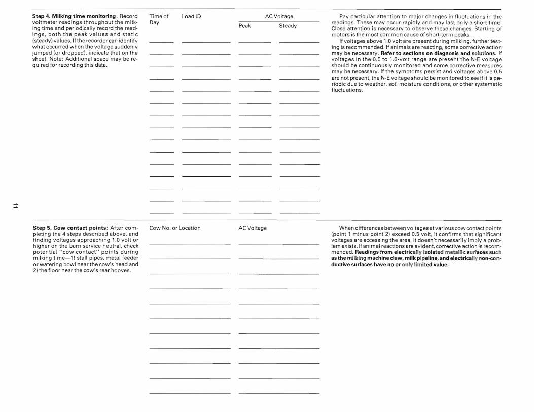
Step 4. Milking time monitoring: Record voltmeter readings throughout the milking time and periodically record the readings, both the peak values and static (steady) values. If the recorder can identify what occurred when the voltage suddenly jumped (or dropped), indicate that on the sheet. Note: Additional space may be required for recording this data.
Time of LoadlD AC Voltage Day
Peak Steady
Pay particular attention to major changes in fluctuations in the readings. These may occur rapidly and may last only a short time. Close attention is necessary to observe these changes. Starting of motors is the most common cause of short-term peaks.
If voltages above 1.0 volt are present during milking, further testing is recommended . If animals are reacting, some corrective action may be necessary. Refer to sections on diagnosis and solutions. If voltages in the 0.5 to 1.0-volt range are present the N-E voltage should be continuously monitored and some corrective measures may be necessary. If the symptoms persist and voltages above 0.5 are not present, the N-E voltage should be monitored to see if it is periodic due to weather, soil moisture conditions, or other systematic fluctuations.
Step 5. Cow contact points: After com Cow No. or Location AC Voltage When differences between voltages at various cow contact points pleting the 4 steps described above, and (point 1 minus point 2) exceed 0.5 volt, it confirms that significant finding voltages approaching 1.0 volt or voltages are accessing the area. It doesn't necessarily imply a probhigher on the barn service neutral, check lem exists. If animal reactions are evident, corrective action is recompotential "cow contact" points during mended. Readings from electrically isolated metallic surfaces such milking time-1) stall pipes, metal feeder as the milking machine claw, milk pipeline, and electrically non-conor watering bowl near the cow's head and ductive surfaces have no or only limited value. 2) the floor near the cow's rear hooves.

Figure 10. Point-to-point voltage measurements at cow contact points
,- - -l I SEBt~I~ E I I ENTRANC E I I I L _ J
STEEL PLATE ON WETTED FLOOR
and the voltage drop across a cow in the circuit estimated. However, this will only be valid ifthe contact resistance for the meter leads are similar to those of the cow. The point-to-point measurement, made with a loading resistor and high contact resistances, may well produce values lower than the cow experiences and varies with concrete and earth moisture.
DIAGNOSTIC PROCEDURES The following procedures have been developed to assist in locating the source or sources of problem-level voltages in livestock facilities. It is assumed t hat the procedures described in th is section w ill be follow ed by persons who: a) have a good understanding of electricity and farmstead wiring, b) have a basic understanding of stray voltage problems, and c) are sufficiently skilled to safely disco nnect and restore distribution panel wiring. Certain portions ofthe test will require the cooperation of the power supplier and can be performed only by authorized utility
personnel . These portions are clearly identified . These tests form a comprehensive check for stray voltage. When testing an in dividual farm, it may become evident that certain tests will not need to be performed as thoroughly as others, or that parts of some tests will be unnecessary or impractical.
Persons using these procedures are encouraged to devise a standardized data sheet for record-keeping. A suggested format is described. A more complete listing of procedures and formats is given in the reference Stray Voltage: Detection and Diagnostic Procedures, Guide For Rural Electric Systems, cited in the appended reference list.
Basic Data
A full farmstead analysis should start with collection of basic data about the farmstead and the problem as experienced by the farmer. Questions related to history of the situation and animal reactions can be helpful in determining problem sou rces. A farmstead map noting the location, am pacity of services and the system voltages (primary and secondary)
should be developed. Suggested questions for the farmer include:
• How long hasthe problem been evident?
• When does the problem occur (time of day, season, weather and soil conditions?)
• Can the problem be related to a specific location such as part of the barn or parlor?
• Whatsymptomsofthe problem have been noticed? (Examples : cows extremely nervous while in parlor, cows reluctant to enter parlor or drink water, in creased manure deposition in parlor, reduced feed intake in the parlor, incomplete or un even milkout, more mastitis, or lowered milk production?)
• Does the problem affect some cows more than others?
• Have sparks been observed or shocks received?
• Who else has been consulted regarding the problem?
• What were the results of any previous tests or measurements?
• What attempts have been made to correct the problem? What effect did they have?
• Is there any other information that may helpto understand the problem?
Voltage Testing Set-Up
The relative contributions of the various sources of stray voltage are usually most easily determined when all voltages are measured to an isolated or "true" ground as outlined in the "Stan dardized Measurements" section. In the following series of tests, two voltages are to be com pared. In the initial test the two voltages are 1) between the transformer ground (primary neutral) and the reference ground, and 2) between the barn service neutral and the reference ground. The use of two voltmeters is recommended so that readings may be taken simultaneously. If the two meters change readings abruptly, avoid reading the voltage on one meter before the change and then reading the voltage on the other meter after the change. See f igure 11 for an illustration of the meter configuration for the first tests.
12

Figure 11. Meter configuration for diagnostic procedures one, two, three, five, six, and seven
DISTRIBUTION FARMSTEAD MAIN QlSCONNECTTRANSFORMER SECONDARY
----------~ ~--~~~~--~--~~--------------~
NEUTRAL
PRIMARY NEUTRAL
l BARN
I SERVICE ICONNECT VOLTMETER LEAD TO GROUND IENTRANCEI CONDUCTOR I I
L __J
VOLTMETER READINGS TRSF -IG BARN -IG
IV~TI IV~TI METER METER
ISOLATED GROUND
GROUNDING ELECTRODE
Figure 12. Meter configuration for diagnostic procedure four
MILK LINES AND OTHER METAL PIPES FANJtL
I BARN I I SERVICE I I ENTRANCE I I I l-:_ _J
VOLTMETERS ARE USED TO LOCATE ELECTRICAL PROBLEMS
BARN-IG MOVI NG PT. - IG
IV~TI IV~TI METER METER
= FLOOR DRAIN
MILKING AREA WITH SAMPLE MEASUREMENT LOCATIONS
WATER FAUCET
13
DETAILED DIAGNOSTIC PROCEDURES
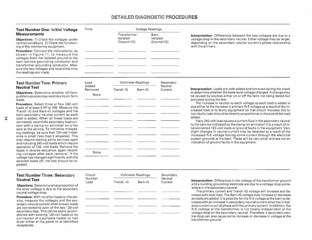
Test Number One: Init ial Voltage Time Voltage Readings
Measurements Objectives: 1) Check the voltages under normal conditions. 2) Check the function
TransformerIsolated Ground (IG)
BarnIsolated Ground (I G)
Interpretation : Differences between the two voltages are due to a voltage drop in the secondary neutral. Either voltage may be larger, depending on the secondary neutral current's phase relat ionship
ing of the monitoring equipment. with the primary.
Procedure: Connect the voltmeter(s), as shown in figure 11, to measure the voltages from the isolated ground to the barn service grounding conductor and transformer grounding conductor. Measure the two voltages and record the time the readings are made.
Test Number Two: Primary Load Voltmeter Readings Secondary Added/ NeutralNeutral Test
Barn-IG Interpretation: Loads are both added and removed during the check Objectives: Determine whether off-farm to determine whether the base-level voltage changed. Achange may
Removed Transf. -IG Current
Noneproblem sources may exist due to on-farm be caused by sources either on or off the farm not being tested but loads. activated during the test.
The increase in neutral-to-earth voltage as each load is added is Procedure: Select three or four 240-volt due either to the increase in primary N-E voltage as a result of the inloads of at least 3 HP or KW. Measure the creased load or to faulty equipment on that circuit. Increase due toTransf.-IG and Barn-IG voltages and the non-faulty load should be directly proportional to the size ofthe loadbarn secondary neutral current as each ...... added . load is added. When all these loads are"'" connected, record the secondary load cur If any 240-volt load causes a current flow in the secondary neutral to the barn (as indicated by the clamp-on ammeter) it is a result of inrent with a clamp-on ammeter on a hot terconnected 120-volt loads or ground faults in the equipment. Verywire at the service. To minimize misleadslight changes in neutral current may be detected as a result of theing readings, be sure that 120-volt imbalincreased N-E voltage forcing some current through the electricalance is small (less than 5 amperes) . This system grounds atthe barn. These will be very small and are not anmay require leaving some services open indication of ground faults in the equipment.and not using 240-volt loads which require
operation of 120- volt loads. Remove the loads in reverse sequence, again record
Noneing voltages after each removal. If the voltage has changed significantly with the selected loads off, the test should be repeated.
Test Number Three: Secondary Circuit Voltmeter Readings Secondary Number NeutralNeutral Test Interpretation : Differences in the voltage of the transformer groundLoad Transf.-IG Barn-IG Current
and a building grounding electrode are due to a voltage drop someObjectives: Determine what proportion of where in the secondary neutral. the stray voltage is due to the secondary
The primary current and Transf.-IG voltage will increase and deneutral voltage drop. crease with total load. The Barn-IG voltage may increase or decrease
Procedure: With no other loads on the ser as loads are added. It is possible for the N-E voltage at the barn to device, measure the voltages and the sec crease with an increase in secondary neutral current when the imbalondary neutral current when known loads ance current is out of phase with the primary current. In addition, theare connected to each of the two 120-volt N-E voltage at the transformer is not totally independent of thesecondary legs. This can be easily accom voltage drop on the secondary neutral. Therefore, a secondary neuplished with existing 120-volt loads or by tral drop can also cause some increase or decrease in voltage at theconnection of a portable heater or hair transformer ground.dryer either at the panel or at identif ied receptacles.

If a significant difference (perhaps 0.5 volt or more) exists between the two N-E voltages, the secondary neutral voltage drop may be contributing to the problem. Improved connections, better balancing of 120-volt loads, use of 240-volt rather than 120-volt motors, and/or a larger neutral wire may help alleviate the problem.
Test Number Four: Object Voltage Readings
Locating Electrical Problems in Milking Area Equipment
Moving Pt.-IG Barn-IG Interpretation: Differences in the voltage at the barn service entrance, and electrically conductive equipment in the barn or milking
Objective: Determine the locations of any equipment or wiring faults which may contribute to stray voltage and find equipment which may not be effectively grounded. Procedure: Maintain the Barn-IG volt
areas is due to faulty equipment, improper wiring, induced voltages, or other voltage sources within these areas.
Ifthe voltage on a test object is greater than the Barn-IG voltage, a wiring or electrical fault is likely in that area. Ifthe voltage is substantially below the Barn-IG voltage, it is likely that the object is not effectively equipment grounded.
meter connection , but replace the Transf.IG lead with a lead connected to a sharp movable probe (figure 12). While equipment operates, contact the probe to metal objects in milking area. Record the two voltages as each object is tested.
Test Number Five: Alternative A: Voltmeter Readings Further Monitoring
Time Transf.-IG Barn-IG Interpretation: These voltage fluctuations are often detected as ...... Objective: Monitor voltages to detect poCJ1 needle deflections on analog meters and as abrupt, momentaryPeak Static Peak Statictential short-term problem-level voltages jumps in reading on a digital meter. Some meters may not detect
which may not have been detected previ these short-term voltages or follow their full magnitude.ously. If voltages are not at a level immediately indicating a problem, Procedure: further monitoring, possibly including seasonal monitoring, may be Alternative A: Milking time monitoring. helpful. Have someone watch the voltmeters throughout milking time and periodically record both the peak and steady-state voltage readings, and the time of these readings. Alternative B: Continuous monitoring. Connect a voltage recorder to monitor the Barn-IG and Transf.-IG voltage (figure 13). Record times on the chart periodically, as well as starting and stopping of such events as milking and feeding operations.
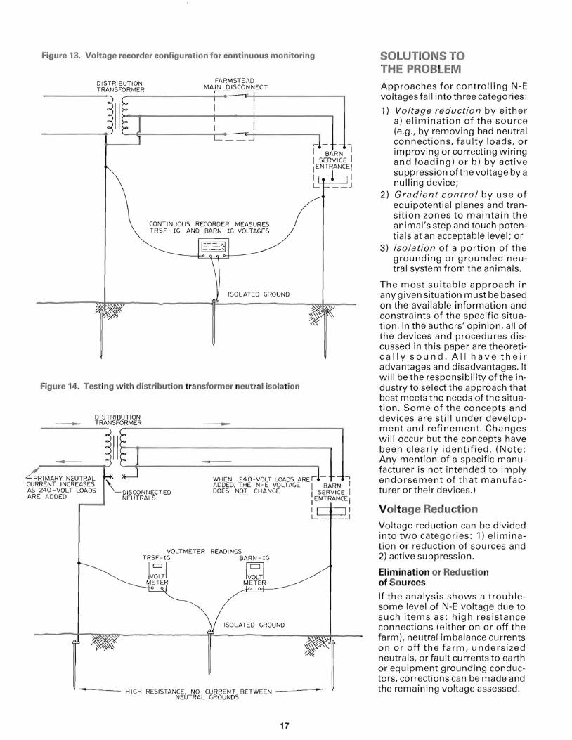
Figure 13. Voltage recorder configuration for continuous monitoring
FARMSTEADDISTRIBUTION MAIN DISCONNECTTRANSFORMER ,- -
CONTINUOUS RECORDER MEASURES TRSF IG AND BARN - IG VOLTAGES
ISOLATED GROUND
~ ~ARN """1
I SERVICE I [ENTRANCEI
I I
Figure 14. Testing with distribution transformer neutral isolation
DISTRIBUTION ___ TRANSFORMER __
-IMAR--Y N::-UTRAL Ilh lr-~-----'l PR - ~ WHEN 240-VOLT LOADS ARE ,1- J-,[
CURRENT INCREASES ADDED. THE N-E VOLTAGE I BARN AS 240-VOLT LOADS DISCONNECTED DOES NOT CHANGE [ SERVICE I ARE ADDED NEUTRALS I ENTRANCE I
I I _:..1
VOLTMETER READINGS TRSF -IG BARN -IG
IV~TI METER
ISOLATED GROUND
---- HIGH RESISTANCE. NO CURRENT BETWEEN - - -NEUTRAL GROUNDS
17
SOLUTIONS TO THE PROBLEM Approaches for controlling N-E voltages fall into three categories:
1) Voltage reduction by either a) elimination of the source (e.g., by removing bad neutral connections, faulty loads, or improving orcorrecting wiring and loading) or b) by active suppression of the voltage by a nulling device;
2) Gradient control by use of equipotential planes and transition zones to maintain the animal's step and touch potentials at an acceptable level; or
3) Isolation of a portion of the grounding or grounded neutral system from the animals.
The most suitable approach in any given situation must be based on the available information and constraints of the specific situation. In the authors' opinion, all of the devices and procedures discussed in this paper are theoretically sound. All have their advantages and disadvantages. It will be the responsibility of the industry to select the approach that best meets the needs of the situation. Some of the concepts and devices are still under development and refinement. Changes will occur but the concepts have been clearly identified. (Note: Any mention of a specific manufacturer is not intended to imply endorsement of that manufacturer or their devices.)
Voltage Reduction Voltage reduction can be divided into two categories: 1) elimination or reduction of sources and 2) active suppression.
Elimination or Reduction of Sources
If the analysis shows a troublesome level of N-E voltage due to such items as: high resistance connections (either on or off the farm), neutral imbalance currents on or off the farm, undersized neutrals, or fault currents to earth or equipment grounding conductors, corrections can be made and the remaining voltage assessed.
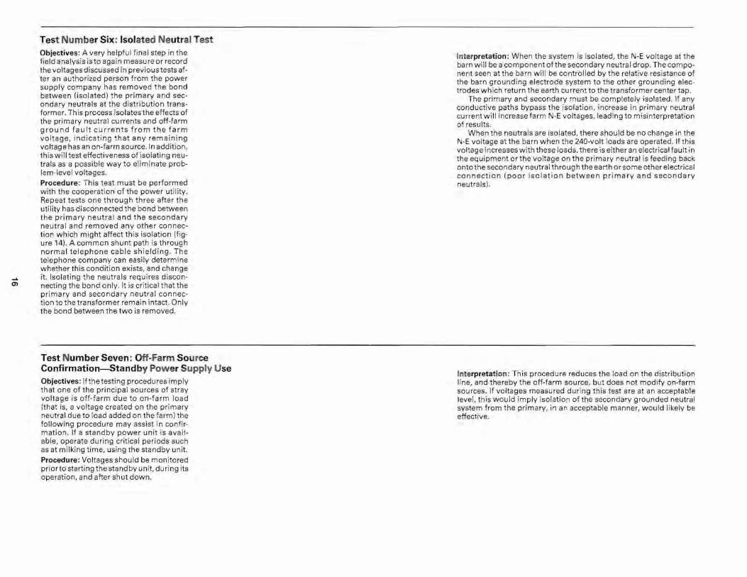
Test Number Six: Isolated Neutral Test Objectives: A very helpful final step in the field analysis is to again measure or record the voltages discussed in previous tests after an authorized person from the power supply company has removed the bond between (isolated) the primary and secondary neutrals at the distribution transformer. This process isolates the effects of the primary neutral currents and off-farm ground fault currents from the farm voltage, indicating that any remaining voltage has an on-farm source. In addition , this will test effectiveness of isolating neutrals as a possible way to eliminate problem-level voltages. Procedure : This test must be performed with the cooperation of the power utility . Repeat tests one through three after the utility has disconnected the bond between the primary neutral and the secondary neutral and removed any other connection which might affect this isolation (figure 14). A common shunt path is through normal telephone cable shielding. The telephone company can easily determine whether this condition exists, and change
..... it. Isolating the neutrals requires discon0') necting the bond only. It is critical that the
primary and secondary neutral connection to the transformer remain intact. Only the bond between the two is removed .
Interpretation: When the system is isolated, the N-E voltage at the barn will be a component of the secondary neutral drop. The component seen at the barn will be controlled by the relative resistance of the barn grounding electrode system to the other grounding electrodes which return the earth current to the transformer center tap.
The primary and secondary must be completely isolated. If any conductive paths bypass the isolation, increase in primary neutral current will increase farm N-E voltages, leading to misinterpretation of results.
When the neutrals are isolated, there should be no change in the N-E voltage at the barn when the 240-volt loads are operated. If this voltage increases with these loads, there is either an electrical fault in the equipment or the voltage on the primary neutral is feeding back onto the secondary neutral throug h the earth or some other electrical connection (poor isolation between primary and secondary neutrals).
Test Number Seven: Off-Farm Source Confirmation-Standby Power Supply Use Objectives: If the testing procedures imply that one of the principal sources of stray voltage is off-farm due to on-farm load (that is, a voltage created on the primary neutral due to load added on the farm) the following procedure may assist in confirmation. If a standby power unit is available, operate during critical periods such as at milking time, using the standby unit. Procedure: Voltages should be monitored priorto starting the standby unit, du ring its operation, and after shut down.
Interpretation : This procedure reduces the load on the distribution line, and thereby the off-farm source, but does not modify on-farm sources. If voltages measured during this test are at an acceptable level, this would imply isolation of the secondary grounded neutral system from the primary, in an acceptable manner, would likely be effective.

Figure 15. A four-wire feeder f rom fa rm main to outbuilding
SERVICE
4-WIRE FEEDER
SERVICE
MAIN
L
NEUTRAL BUS
l BUILDING
I I I
-.l
Figure' 16. Voltage suppression by controlled current to earth
~l-~ 1 NULLING DE VIC E I BARN ISERVICE'-l.----------i--,IENTRANCE I POWER SOURCE
I~~~----------------~~--~ L_
SENSING INPUTS
OUTPUT TO REMOTE ELECTRODE SYSTEM
SERVI CE GROUNDING REFEREN CE REMOTE
GROUND GROUNDING SYSTEM
Improvement of grounding on the distribution neutral can reduce the N-E voltage due to system loading. Since that portion of the system grounding supplied by the farmsteads is often large compared to that by the distribution neutral, the effectiveness of this approach may be limited. It is important to recognize much of the system grounding on the farmstead is supplied by items which are equipment grounded and in contact with the earth .
If the farmstead system contains unusually long secondary neutrals, an option of using a fou r-wire service to the building is allowed by the National Electric Code (NEC). Figure 15 shows a schematic of the four-wire system. This will eliminate the secondary neutral drop on the four-wire system from contributing to the N-E voltage at the building service. For this system, all neutral and grounding conductors in the building service and all feeders from that service must be completely separated. Also, the originating end must meet all NEC Article 230 requirements as a service, (i .e ., disconnect with overcurrent protection, system grounding, appropriate enclo sure, and neutral-to-ground bonding connection). N-E voltages will remain from all other sources.
Active Volt age Suppression
Since N-E voltage is created by current flow through a system impedance, it is possible to create a potential source which nulls or cancels the original source at that point in the system .
One procedure is to deliver a controlled current to earth (figure 16) . Voltage between a point in the neutral system and an isolated reference ground or grounds is used as the input to a differential amplifier . Current to remote grounding electrode system is then adjusted to null outthe N-E Voltage. Th is method has been developed by Blackburn Co. of St. Louis, MO. The voltage is also reduced on farms served by the same primary line and located
18
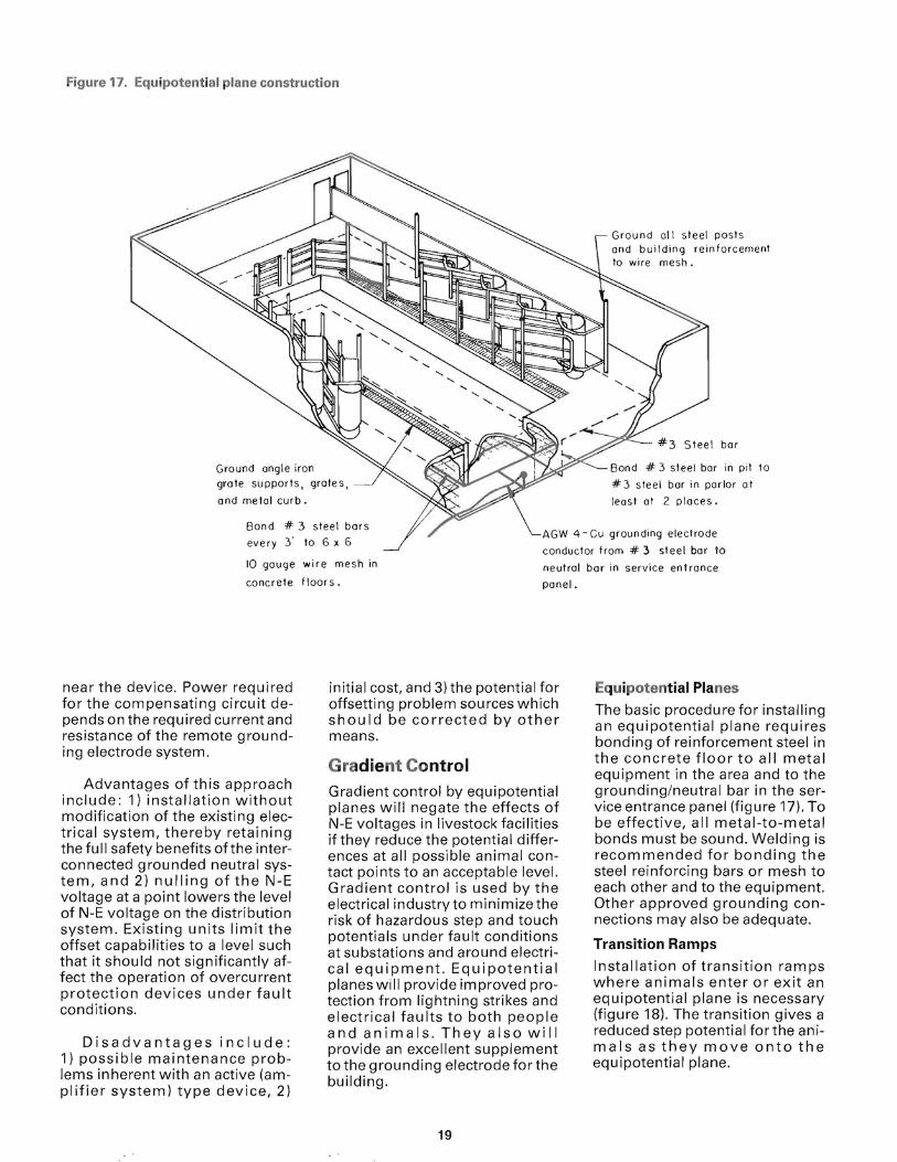
Figure 17. Equipotential plane construction
Ground all steel posts and building reinforcement to wire mesh.
Ground angle iron # 3 steel bar in pit to
grate supports, grates, # 3 steel bar in parlor at
and metal curb. least at 2 places.
Bond # every 3'
10 gouge
concrete
near the device. Power required for the compensating circuit depends on the required current and resistance of the remote grounding electrode system.
Advantages of this approach include: 1) installation without modification of the existing electrical system, thereby retaining the full safety benefits ofthe interconnected grounded neutral system, and 2) nulling of the N-E voltage at a point lowers the level of N-E voltage on the distribution system. Existing units limit the offset capabilities to a level such that it should not significantly affect the operation of overcu rrent protection devices under fault conditions.
Disadvantages include: 1) possible maintenance problems inherent with an active (amplifier system) type device, 2)
3 steel bars
to 6 x 6 AGW 4 - Cu grounding electrOde
conductor from # 3 steel bar to wire mesh in neutral bar in service entrance floors. panel.
initial cost, and 3) the potential for offsetting problem sources which should be corrected by other means.
Gradient Control Gradient control by equipotential planes will negate the effects of I\J-E voltages in livestock facilities if they reduce the potential differences at all possible animal contact points to an acceptable level. Gradient control is used by the electrical industry to minimize the risk of hazardous step and touch potentials under fault conditions at substations and around electrical equipment. Equipotential planes will provide improved protection from lightning strikes and electrical faults to both people and animals. They also will provide an excellent supplement to the grounding electrode for the building.
Equipotential Planes
The basic procedure for installing an equipotential plane requires bonding of reinforcement steel in the concrete floor to all metal equipment in the area and to the grounding/neutral bar in the service entrance panel (figure 17). To be effective, all metal-to-metal bonds must be sound. Welding is recommended for bonding the steel reinforcing bars or mesh to each other and to the equipment. Other approved grounding connections may also be adequate.
Transition Ramps
Installation of transition ramps where animals enter or exit an equipotential plane is necessary (figure 18). The transition gives a reduced step potential forthe animals as they move onto the equipotential plane.
19

Figure 18. Transition ramps for equipotential planes to maintain or reduce the N-E
Procedures for retrofitting existing facilities with equipotential planes are being studied. One possibility is to groove the concrete, insert a copper conductor, and reg rout the groove. Necessary spacing, locations, longevity, and effectiveness have not yet been established.
Equipotential systems can successfully minimize stray voltage problems regardless of the source. However, additional work is needed to clarify installation procedures for both new and existing facilities. When using this approach, consideration must be given to all areas where electrically grounded equipment is accessed by the livestock or exposed to livestock traffic. Additional corrective procedures may be needed when all areas cannot be protected with an equipotential plane.
Isolation Isolation of part of the grounded neutral system can prevent the source from accessing the animals. If isolation is used there are two locations where it can be accomplished on a conventional multi-grounded system. They are:
6 x 6, 10 go Welded Wire Mesh
Welding Preferred.
Approved Grounding Connectors acceptable
~ # 3 Copper C lad Steel Bar
1) whole farm isolation at the farm's main service entrance and 2) single service isolation at the livestock building. Whenever isolation is used, careful consideration must be given to the safety and operational effects.
Whole Farm Isolation
Whole farm isolation can be accomplished by: 1) isolation at the distribution transformer with a surge arrestor or a switching/reconnect device or 2) with an isolation transformer following the distribution transformer. Either way, some system grounding will be removed from the distribution system, at least during non-fault conditions. This can affect both off-farm and on-farm sources of N-E voltage.
Under non-fault conditions, isolation of the farmstead removes its grounding from the primary grounded neutral system. This increases the resistance of the distribution neutral and results in increased primary N-E voltage. Isolation does raise the concern that the N-E voltage at neighboring farms may be raised to a problem level, particularly for those in proximity. In these cases further action may be necessary
voltage.
Isolation removes contributions from off-farm sources. However, it will also affect on-farm sources resulting from secondary neutral voltage drops and onfarm faults . Some generalizations can be made about redistribution of N-E voltages due to secondary neutral voltage drops after primary-secondary isolation. N-E voltage at a service entrance due to a voltage drop on the secondary neutral to that service will be reduced as a result of isolation. This occurs since the grounding resistance at the service remains the same while the grounding resistance atthe transformer end increases . Conversely the N-E voltage at one service entrance will increase due to a voltage drop on the secondary neutral to another service as a result of isolation. This occurs since the grounding resistance at the other service remains the same, whereas the grounding resistance at the transformer end, including the service, increases. The mag nitude of the changes will be determined by the system grounding resistances at all service entrances on the farm. After isolation, the location of an electrically grounded water well casing will have a major effect on the redistribution of N-E voltage due to secondary neutral voltage drops.
Primary-secondary neutral isolation will also affect N-E voltage due to on-farm fault currents to earth. Since the resistance of the retu rn path ofthe fault current to the transformer is increased, the N-E voltage contribution will be increased proportionally.
A vai/ab/e Devices For Neutra/ /solation at Distribution Transformer
Three methods have been developed for isolating the primary and secondary neutrals at the distribution transformers (figure 19). They make use of: 1) conventional spark gap, 2) a saturable reactor (Ronk Blocker, Hammond
20

Figure 19. Distribution transformer neutral isolation
PRIMARY ' NEUTRAL
BONDING STRAP AND
OTHER INTERCONNECTS -
REMOVED
TANK GROUNDING LUG
INSULATED GROUNDING CONDUCTOR ------~
6 F T
Tingle Voltage Filter), or 3) a solid state switch (Dairyland Neutral Isolator). These methods provide a high impedance interconnect below a specified threshold voltage and a low impedance interconnect when the voltage exceeds that threshold. The "high" impedance is relative to the grounding impedance of the isolated secondary system. The "low" impedance provides that, under any condition creating a primary to secondary voltage above the threshold level, the device impedance will be reduced to a value such that the neutrals are essentially bonded.
Several types of conventional low voltage lightning arrestors are being used for this application. Since most of these gaps are designed as low-current devices, their use may be restricted to systems with appropriate limitations on fault currents.
SECONDARY NEUTRAL
MIN. -------..-1
Saturable reactors designed to give an impedance change threshold in the range of 10 to 24 volts AC are also in use . Below saturation voltage, the high impedance provides isolation. Above saturation, the impedance drops to a very low level to provide neutral interconnection. These devices also include a surge arrestor to divert fast rising transient voltages, such as lightning. Such transients would otherwise create high voltages across the reactors.
The solid state switching device is equipped with two thyristors and a control circuit for each. The control circuit triggers the thyristors when an instantaneous voltage above the specified threshold occurs across the device. The device remains in a low impedance state until the voltage differential reaches zero. For a 60 Hz waveform whose peak is above the threshold, the device triggers during each half cycle
21
and remains closed for the remainder of the half cycle. This device also has a surge arrestor in parallel to assist in passing fast risi ng tra nsients.
Conditions may occur where voltage between the primary and secondary grounded neutral systems can saturate or trigger the isolation device during part cycles of the AC power waveform. For example, these can exist when the voltages approaching saturation or triggering levels occur due to a short-term large load. If relatively high primary N-E voltages already exist, a large motor start may raise the distribution system load for a short period and result in voltages that will cause partial satu ration of satu rable reactors or will create part-cycle closure of the solid state switch. This leads to non-sinusoidal N-E voltage on the secondary grounded neutral.
Since most volt-ohm meters (VOM's) commonly used for monitoring and trouble shooting read only rms values, they will not provide the necessary data on N-E voltages occurring due to part cycle saturation or triggering. A peak detecting meter or oscilloscope type instrument will be needed.
Whole Farm Isolation with Isolating Transformer
Isolating transformers, such as shown schematically in figure 20, have been used in the past to create a separate grounded neutral system on the farmstead. In this system, a primary-to-secondary fault in the distribution transformer is carried by the distribution system neutral and grounding. Such systems represent an investment in the range of $1,000 to $3,000, plus the cost of operating the transformer. Care must be taken in proper installation to meet prevailing codes and recommendations, particularly for overcurrent protection and bonding. When an isolating transformer is installed, assurance is necessary that no conductive interconnections are bypassing the transformer. Common interconnections are metallic

- -----
telephone grounds , gas or water pipes , metal feeders , fences and connected metal buildings. Any conductive bypass will negate the isolation of the transformer.
Single Building Service Isolation
If a satisfactory solution can be obtained by isolation of a single building service, an isolating transformer can be used for a single service as shown in figure 21. Depending on farmstead load , the transformer for the single service can be smaller and less expensive than a transformer for the entire farmstead. In this location, the transformer also elim inates secondary neutral voltage drops from affecting the isolated system and minimizes the loss of system grounding to the remainder ofthe system. However, in many dairy facilities the principle system grounding is from the barn.
A second approach to single service isolation has been developed in, and is used in, Canada (Hammond Tingle Filter) . This approach makes use of a saturating reactor for separating the grounded (neutral) conductors from the grounding conductors and electrode , at the building service entrance. The advantage of this approach is its low cost. However, installation may be difficult in some existing facilities since its function is dependent on complete separation of grounding and neutrals within the service and separation of grounding systems between services. Fu rthermore, the National Electrica l Code has not approv ed th e use of this device in the United States. Thus, it ca nnot be recommended unless approved by app rop riat e electrical inspection authorities on an experimental basis.
Figure 20. Isolation transformer installation-whole farmstead
MAI N DISCONN ECT WITH OVERCU RRENT SURGE ARR ESTER
LnII H TO DISTR IBUT ION
TRANS FORMER
SERVI CES
PROTECT ION
!
L_
TRAN SFORMER CASE BOND ED TO SUPPLY SIDE ONLY (CO NSULT l OCAL CO DE
AUTHORITY)
BUilDING
Figure 21 . Isolation transformer installation-single service
FARMSTEAD MAI N DISCONNECT
t , - -
L __ J
DISCONNEC T
TRANSFORMER CASE BONDED SUPPLY SIDE ONLY
I I L
TO
TO DISTRIBUTI ON TRANSFORMER
TRANSFORMER
~~gT~tft~~URRENT I (liL __ J
OTHER SERVICE
ISOLATING TRANSFORMER
ANY LOW RESISTANCE INTERco ..·,cr T'''.• ,,, Nlill BY- PASS THE ISOLATIO N TRANSFORMER AND RENDER TH E CONNECTI ON INEFFECTIVE -- /
22

APPENDIX I-TESTING EQUIPMENT Voltmeter(s). To avoid improper voltage readings, only instruments meeting the following criteria and tests should be used.
• The meter should have an AC voltage scale with a full scale reading of two to five volts, and capability of reading to 0.1 or 0.01 volt.
• The meter should have a relatively high input impedance (5,000 ohms per volt, AC or higher). Very low-impedance meters may read low because of the voltage drop in the external circuit.
• The meter should not read DC voltage on the AC scale. This can be checked as follows: Connect the voltmeter(s) to be used to a conventional dry cell battery (1.5 - 6 vOlt). If a meter deflection is obtained on the AC voltage scale, install a five or ten microfarad capacitor in series with one voltmeter lead.
Any voltmeter meeting the above specifications and tests will generally be satisfactory. However, confusion may be created if a high impedance meter, like most digital meters, is used to measure from non-metallic or ungrounded objects. In this case, voltages from truly high impedance sources (very low current- producing capability) can be measured by the meter. Since these voltages are not of general concern, using a loading resistor of 10 kohm across the meter gives a sufficient indicator of whether or not the source is truly a high impedance source.
Other Equipment Clamp-on Ammeter
Insulated Leads. One lead must be long enough to extend from the isolated ground to the location of the voltmeter, usually at the barn location . Other leads from the transformer ground and to the milking area may be needed. Any wire with sufficient mechanical strength to take repeated winding and unwinding will be satisfactory electrically. Sharp Test Probe. This probe must be sharp enough to make good elec
trical contact through dirt and rust on metal objects in the milking area. Ground Rod . A 4 to 8 foot copperclad ground rod with connecting clamp.
Optional Equipment Mu ltiple Cha nnel Continuous Recorder. Continuous recorder with two or three channels and a range of oto less than 5 volt AC. Portable Oscilloscope. A portable oscilloscope can be helpful in following rapidly changing voltages that may occur due to motor starts or faults. 300- to SOO-ohm Resistor. This resistor can be used for testing the resistance of the isolated reference rod.
APPENDIX II-ELECTRICAL GROUNDING The terms "ground," "grounded," and "grounding" can be very confusing when used in an electrical sense. Although the terms relate, in one way or another, to connections to earth , they should not be confused with "true earth." The National Electric Code and National Electric Safety Code require that ce rtain parts of electrical systems be electrically connected to earth through appropriate "grounding electrodes." One common form of grounding electrode is an 8 or 1 0 foot long metal rod driven into the earth. The wiring systems are then "grounded" by solidly bonding one of the electrical conductors to the grounding electrode. This is referred to as "system" grounding. That is, the electrical "system" is "grounded" or connected to earth through the "grounding electrodes." Other required and acceptable "grounding electrodes" are explained in the applicable codes. The conductor that is connected to earth is called the "grounded" conductor, more commonly referred to as the "neutral."
Another type of electrical "grounding" is referred to as "equipment" grounding. Metal structures and equipment that are properly "grounded" are solidly bonded with a low resistance conductor to the electrical system at the location where it is "system" grounded, (i.e.,
connected to earth through the "grounding electrode") . In contrast to the grounded or neutral conductor, the conductor bonding the metal structures and equipment back to the grounded electrical system is called the "grounding" conductor, or more commonly the "ground" wire.
The extensive network consisting of all parts of the grounded electrical system and all grounded objects is sometimes called the grounded neutral network.
System Grounding
The main reason for "system" grounding is to limit the voltage between any conductor and the earth to a minimum value. Voltage to ground, the voltage between any point in the electrical system and the grounded neutral system, is also minimized. Figure A.1 shows the typical 120/240-volt single-phase system. The neutral wire is "system" grounded. The voltage between any "equipment" grounded object and either hot conductor is 120 volt. The voltage to ground is the lowest possible for a 120/240-volt system, and the voltage from each hot conductor to ground is the same. Both are requirements of the National Electric Code.
Good system grounding is dependent on establishing low resistant paths to earth at each system grounding pOint. The National Electric Code (Article 250-81 ) specifies the requirements for grounding electrodes.
Equipment Grounding
Equipment grounding is necessary to prevent electrical shock to persons or animals coming in contact with metallic objects, which due to some fault, have come in contact with a hot conductor. To illustrate the potential problem, consider the situation in figure A.2. If a fault develops in the motor windings such that the hot conductor comes in contact with the ungrounded frame, a 120-volt potential exists between the motor frame and earth. If a person standing on earth comes in contact with the frame, that person will be subjected to a very hazardous, if not fatal shock. This type of hazard can be avoided by equipment grounding
23

--- ----
Figure A.1 . Voltage to ground for 120/240-volt service
SERVI CE CONDUCTORS ~
HOT NEU HOT
SYSTEM GROUNDING
Figure A.2. Ungrounded motor w ith fault to frame
CONTACT TO WITH FAULT ,- - ---1
I I HOT
I NEUTRAL
I S~~~I~ EI ENTRANCE
I I L ...J
MOTOR TO FRAME
DANGEROUS FAULT CURRENT PATH
120 VOLT
the frame as shown in figure A.3. If the hot conductor were to come in contact with the frame, a short circuit would exist, and the overcurrent protection for the circuit would then "blow" or open the circuit due to the high current flow. Even during the fault, the voltage rise on the motor frame should be limited to a safe level for a person in contact with it.
Use of grounding electrodes at remote equipment cannot substitute for equipment grounding. As shown in figure A.4, if a fault occurs to a piece of equipment which is not equipment grounded, the fault current will not open the overcurrent protection because of the relatively high resistance of the ground rod.
APPENDIX 111REFERENCES FOR FURTHER STUDY
Animal Sensitivity Appleman, R.D. and R.J. Gustafson. 1985. Sources ofstray voltage and effect on cow health and performance. J. Dairy Sci. 68:1554-1567. Gustafson, R.J., R.D. Appleman and T.M. Brennan. 1986. Electrical current sensitivity ofgrowingffinishing swine for drinking. Trans. of American Society of Agricultural Engineering, 29(2) :592-596,600.
Understanding Sources of St ray Voltage Gustafson, R.J., H.A. Cloud, and RD. Appleman. 1982. Understanding and dealing with stray voltage problems. Bovine Practitioner 17 (I\lov) :4-15. Gustafson, R.J. and D.J. Hansen. 1985. Distribution and farmstead neutralto-earth voltage modeling-A personal computer application. Research Publication 85-A , Nati . Rural Elec. Coop . Assoc., 1800 Mass. Ave. N.w., Washington, DC 20036.
Methods For Source Determination Gustafson, R.J. 1983. Stray voltage : detection and diagnostic procedures, guide for rural electrical system. Research Publication 80-1 , Natl. Rural Elec . Coop . Assoc., 1800 Mass. Ave. N.w., Washington , DC 20036.
Solution Procedures Gustafson, R.J. and HA Cloud . 1986. Availa ble procedures for stray voltage problem solution. Research Publication 86 -A , Natl. Rur a l Elec . Coop. Assoc. , 1800 Mass. Ave. N.w., Washington , DC 20036.
24

Gustafson, R.J. and H.A. Cloud. 1986. Equipotential plane installation. Research Publication 86-8, Nail . Rural Elec. Coop. Assoc., 1800 Mass. Ave . N.W., Washington DC 20036. Gustafson, R.J. and V.D. Albertson. 1986. Distribution transformer primary to secondary isolation devices and system responses. Paper No. 86 T&D 530-0, Instil. of Elec. and Electronic Eng ., New York, NY.
Issued in furtherance of cooperative extension work in agriculture and home economics acts of May 8 and June 30, 1914, in cooperation with the U.S. Department of Agriculture, Patrick J. Borich, Director of Minnesota Extension Service, University of Minnesota, St. Paul, MN 55108. The University of Minnesota, including the Minnesota Extension Service is committed to the policy that all persons shall have equal access to its programs, facilities, and employment without regard to race, religion, color, sex, national origin, handicap, age, veteran status, or sexual orientation .
The information given in this publication is for educational purposes only. Reference to commercial products or trade names is made with the understanding that no discrimination is intended and no endorsement by the Minnesota Extension Service is implied.
Figure A.3. Grounded motor with fault to frame
CONTACT TO MOTOR WITH FAULT TO FRAME1-----'
I ~~,~~------~--____I 1
1
1
1
L
BARN SERVICE
ENTRANCE
120 VOLT
FAULT CURRENT PATH (HIGH RESISTANCELOW CURRENT)
Figure A.4. System grounding at remote equipment
1-----1 I ~--~~HO~
I NEUTRAL
I I I L --.J
T ----1-~~~~~
I J